Tempest® Hot Air Drying System Installation Instructions
Tempest® Hot Air Drying System Installation Instructions
Tempest® Hot Air Drying System Installation Instructions

Create successful ePaper yourself
Turn your PDF publications into a flip-book with our unique Google optimized e-Paper software.
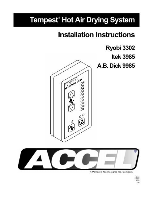
Tempest ® <strong>Hot</strong> <strong>Air</strong> <strong>Drying</strong> <strong>System</strong><br />
<strong>Installation</strong> <strong>Instructions</strong><br />
Ryobi 3302<br />
Itek 3985<br />
A.B. Dick 9985<br />
X88-43<br />
01/2001<br />
Rev-B<br />
2740
GENERAL INFORMATION<br />
ATTENTION<br />
TEMPEST ® DRYER<br />
OWNER!<br />
Accel Graphic <strong>System</strong>s provides parts and service through its<br />
authorized distributors and dealers. Therefore, all requests for<br />
parts and service should be directed to your local dealer.<br />
The philosophy of Accel Graphic <strong>System</strong>s is to continually improve<br />
all of its products. Written notices of changes and improvements<br />
are sent to Accel Graphic <strong>System</strong>s' Dealers.<br />
If the operating characteristics or the appearance of your product<br />
differs from those described in this manual, please contact your<br />
local Accel Graphic <strong>System</strong>s Dealer for updated information and<br />
assistance.<br />
Always update your equipment when improvements are made<br />
available, especially those related to safety.<br />
YOUR AUTHORIZED TEMPEST ® DEALER IS:<br />
THE SERIAL NUMBER OF YOUR<br />
TEMPEST ® HOT AIR DRYING SYSTEM IS:<br />
CONTROL BOX<br />
FAN UNIT<br />
2<br />
TECHNICAL<br />
ASSISTANCE<br />
For technical assistance during the installation, please contact:<br />
ACCEL GRAPHIC SYSTEMS<br />
11103 INDIAN TRAIL<br />
Dallas, TX 75229<br />
PHONE (972) 484-6808<br />
FAX (800) 365-6510<br />
E-MAIL accel@dallas.net<br />
WEB SITE www. accelgraphicsystems.com
GENERAL INFORMATION<br />
ELECTRICAL<br />
REQUIREMENTS<br />
220 VAC 50/60 HZ<br />
20 AMP DEDICATED LINE<br />
NEMA L620R RECEPTACLE<br />
IMPORTANT<br />
INFORMATION<br />
The use of heat to accelerate drying may require more frequent<br />
lubrication and/or use of a high temperature lubricant in the delivery of<br />
the press. Please consult your press manufacturer for specific recommendations.<br />
SAFETY<br />
INFORMATION<br />
The Tempest ® Dryer contains high voltage and hot surfaces. Never<br />
attempt to service or work on the unit unless the power is shut off and<br />
the unit is cool.<br />
Visually inspect the thermistors (Barn housed-shaped objects arranged<br />
in a honeycombed pattern on the underside of the unit) weekly.<br />
If a thermistor is damaged or cracked, do not operate the dryer. Contact<br />
Accel immediately for a replacement part.<br />
The fans should be turned on and set at the lowest speed ("0" on the<br />
dial) when running spray powder only without heat. This prevents<br />
spray powder from accumulating in the thermistors and housings.<br />
TERMINOLOGY<br />
OPS = Operator's Side<br />
NOPS = Non Operator's Side<br />
3
GENERAL INFORMATION<br />
HOT AIR<br />
VS INFRARED<br />
WHAT MAKES<br />
TEMPEST ® WORK<br />
Although the technology behind the Tempest ® dryer was significant<br />
enough to be awarded the GATF Intertech Award, it is by no means<br />
new. In fact, thermistors have been in use for many years. They<br />
were originally used in motors and other devices as a heat<br />
controller and later used in refrigeration to turn compressors on and<br />
off. It is only in the last 10 years or so that thermistors have been<br />
used as a heater.<br />
Heat is generated by the thermistor because of the difficulty of<br />
electricity travelling through it when it is a conductor. The thermistor<br />
acts as a conductor until it reaches its set temperature and then it<br />
becomes a resistor. A thermistor is basically a coated<br />
semiconductor designed to switch from a conductor to a resistor at<br />
an established temperature.<br />
When a current is applied to the thermistor it initially uses a large<br />
amount of electricity and heats up very quickly until it reaches its<br />
maximum set temperature. At this point it should not use any more<br />
electricity. However, air that is passed through the holes in the<br />
thermistor causes it to cool. This activates the thermistor to start<br />
using more power again so that can get back to its set temperature.<br />
The thermistor is constantly regenerating itself to stay at a constant<br />
temperature. This process is called autostabilization.<br />
Thermistors are also the key element that makes the Tempest ®<br />
dryer safe. Because the set temperature of the thermistor is lower<br />
than the flash point of paper, you can place even the most easily<br />
burned substrate (such as tissue paper) on top of the thermistor<br />
element without causing a fire. The tissue won't even char, let<br />
alone ignite. If you were to do the same with an IR element, a fire<br />
could start in a matter of seconds. This is particularly important if a<br />
jam occurs in the delivery.<br />
The objective of any drying system is to raise the pile temperature<br />
to accelerate the drying of the ink. However, heating the paper too<br />
much can aggravate problems such as blocking, setoff, mottle, loss<br />
of gloss, and loss of halftone definition. Too much heat can also<br />
cause the paper to shrink which can cause register problems in<br />
multiple pass work. The Tempest ® dryer can keep the pile at a<br />
lower temperature than IR and still effectively set the ink film.<br />
4
GENERAL INFORMATION<br />
IR dryers use very high temperatures and a fixed amount of electricity.<br />
One of the drawbacks of using a very hot heat source is that heat wants<br />
to travel from a very high temperature to a very low temperature. In<br />
other words, the heat generated from an IR dryer will travel to the press<br />
wall and attempt to increase its temperature because it is cooler than<br />
the heat produced by the IR dryer. Because the thermistors used in the<br />
Tempest ® dryer use lower temperatures, the heated air has had time<br />
to cool by the time it reaches the wall of the press, reducing the chance<br />
of premature wear to press parts.<br />
HOW DRYING IS<br />
ACCOMPLISHED<br />
WITH TEMPEST ®<br />
Tempest ® "sets" the surface of the ink to prevent set-off from one sheet<br />
to another and to minimize the use of powder.<br />
Tempest ® accelerates the final drying of oil based inks by raising the<br />
temperature of the delivery stack.<br />
KEY FACTORS<br />
TO REMEMBER<br />
ABOUT DRYERS<br />
FOR SMALL<br />
OFFSET<br />
PRESSES.<br />
Do not expect a dryer to "instantly" dry the ink. Only UV inks and<br />
coating dry instantly. The technology and hazards of such systems<br />
make them cost prohibitive on small offset presses.<br />
Some jobs may require spray powder. Because dryers for small offset<br />
presses do not dry ink instantly, powder will be required from time to<br />
time. However, you should expect to see a significant decrease in the<br />
amount of powder needed on a regular basis.<br />
<strong>Drying</strong> time is dependent upon press speed, paper stock, ink coverage,<br />
type of ink, etc.<br />
Do not expect a dryer to accelerate the drying of rubber based inks.<br />
These inks dry by absorption into the stock, and heat does not<br />
accelerate this process.<br />
5
INSTALLATION<br />
1<br />
DISCONNECT THE POWER TO THE PRESS BEFORE<br />
BEGINNING INSTALLATION.<br />
Remove the two large side covers over the main framework of the<br />
press (one at OPS and one at NOPS) and the NOPS cover at the<br />
delivery end of the press.<br />
For an easier installation, you may also want to remove the two<br />
guards on the delivery end of the press.<br />
2<br />
NOTE: Do not cut the hose if the press is equipped with an<br />
<strong>Air</strong>tech sprayer.<br />
Cut the sprayer hose about halfway between the hopper and the<br />
spray bar. A new hose will be attached to the spray mechanism.<br />
3<br />
NOTE: Do not remove the spray bar if the press is equipped<br />
with an <strong>Air</strong>tech sprayer.<br />
Remove the spray bar by removing the two bolts holding the<br />
bracket (subject arrow). Also remove the clip holding the spray<br />
hose (subject arrow, picture on following page).<br />
7
INSTALLATION<br />
4<br />
Remove the chain guide (subject arrow) at the OPS & NOPS sides<br />
of the press.<br />
5<br />
Install the mounting bracket and new chain guide using M5 X 16MM<br />
cap head bolts and lock washers (subject arrow) as shown at the<br />
OPS & NOPS. Leave the bolts loose so the position of the dryer can<br />
be moved up and down. The bolts thread into the same holes that<br />
held the original chain guides.<br />
9
INSTALLATION<br />
6<br />
Note: If the press is equipped with an <strong>Air</strong>tech sprayer, you must<br />
remove the spray bar from the dryer before installing it in the<br />
press. To remove the spray bar from the dryer, remove the three<br />
screws on the top of the dryer.<br />
Set the dryer on the brackets with the cable exiting at the NOPS.<br />
Run the cable under the mounting bracket (subject arrow, left<br />
picture) and through the large hole in the side frame (subject arrow,<br />
lower picture) directly under the mounting bracket.<br />
7<br />
Secure the dryer to the brackets (four places) using the short button<br />
head bolts, washer, and flanged nut (subject arrows). Leave the bolt<br />
loose so the dryer can be moved front to back.<br />
11
INSTALLATION<br />
8<br />
Position the dryer so it clears the gripper opening mechanism on all<br />
three delivery gripper bars. The arm must clear both the top and<br />
bottom of the dryer. The photo shows the arm clearing the top of the<br />
dryer (subject arrow). After positioning the dryer, tighten the bolts<br />
holding the mounting brackets to the press frame and the bolts<br />
holding the dryer to the mounting brackets.<br />
9<br />
NOTE: If the press is equipped with an <strong>Air</strong>tech sprayer, proceed<br />
to step 11.<br />
Attach two hoses to the elbows in the sprayer housing (subject<br />
arrow, upper picture) and run the hose through the hole in the side<br />
frame (subject arrow, lower picture ). Note how the hoses are tied<br />
together with a zip tie in the upper picture on the left hand side.<br />
13
INSTALLATION<br />
10<br />
Connect the two hoses together using the "Y" connector (left hand<br />
subject arrow). Connect the Tempest ® Spray line to the press spray<br />
hopper line using the reducer (right hand subject arrow).<br />
11<br />
Attach the exhaust fan/manifold assembly to the center of the<br />
delivery guard as shown. Make sure that the arrow on the fan is<br />
pointing toward the guard (out of the press) and that the wires are<br />
routed toward the NOPS of the press. The top two screws go<br />
through the second slot down from the top of the guard. Make sure<br />
that the open end of the manifold is pointing toward the NOPS. You<br />
will need to file the openings in the guard so that the screws will<br />
pass through the guard.<br />
12<br />
Locate the 2 impression cylinder activation solenoids located on<br />
the OPS of the press, one under each head. Remove the 2 outside<br />
nuts and screws from each solenoid (lower subject arrows). Install<br />
the provided longer M4 x 16MM screws. Install the supplied switch<br />
assemblies (as shown in the picture) over the screws and secure<br />
them using the original hardware.<br />
The left photo show the #1 head solenoid and the right shows the<br />
#2 head solenoid. Note how the microswitch trip arms extend up to<br />
the spring studs located on activation linkage (upper subject<br />
arrows).<br />
15
INSTALLATION<br />
13<br />
Attach the microswitch cable assembly to the microswitch's installed<br />
in step 12. See diagram for proper connection.<br />
14<br />
Find a suitable location for the main Tempest electrical box on<br />
the NOPS of the press. Route the exhaust fan cable (this cable<br />
has female pins in the connector on the end) into the delivery<br />
and connect it to the exhaust fan installed in a previous step.<br />
Route the impression signal cable (this cable has male pins in<br />
the connector on the end) through the press and connect it to<br />
the the cable that was attached to the micro-switches installed<br />
in the previous step. Use the provided tie-wraps to secure the<br />
cable as necessary to clear any moving parts of the machine.<br />
15<br />
Remove the cover from the main Tempest ® electrical cabinet and<br />
insert the dryer cable through the strain relief on the bottom of the<br />
box. Insert the wires into the green connector by matching the<br />
number on the wire to the number on the connector. Secure the<br />
ground wire to the stud on the inside of the box. Tighten the strain<br />
relief and replace the cover on the box.<br />
17
INSTALLATION<br />
16<br />
Remove one of the two screws that attach the guard prop to the<br />
delivery guard on the NOPS. Install the supplied longer M4 screw<br />
in its place and using the original nut secure the provided cable<br />
clamp (subject arrow) to the underside of the guard. Make sure you<br />
have the exhaust fan cable going through the clamp before securing<br />
it to the guard.<br />
17<br />
Place the larger heat shield in the delivery as shown.<br />
18<br />
Place the small heat shield in the delivery and attach it to the larger<br />
shield, with two 10-32 x 1/4 button head screws and flat washers.<br />
19
INSTALLATION<br />
19<br />
Use the provided zip ties to secure all loose cables. See the back<br />
of the manual for a complete electrical system diagram.<br />
Replace all covers and guards.<br />
Attach the supplied multiple power cord caution label to the press<br />
side NOPS cover.<br />
20<br />
21
OPERATION & MAINTENANCE<br />
HOW DRYING IS<br />
ACCELERATED<br />
WITH TEMPEST ®<br />
Tempest ® creates a two-step drying process when used with oil-base<br />
inks. These steps are:<br />
1. Skinning the surface of the ink with the initial blast of hot air to<br />
prevent set off.<br />
2. Accelerating the final drying process approximately 20 o F over the<br />
cold stack temperature in the feeder. Heat accelerates the drying<br />
process, called oxidation and reduction, of oil-based inks.<br />
In general, dryers including infrared do not work well with rubber or<br />
acrylic-based inks. These inks should be avoided when maximum<br />
results are desired.<br />
HOW TEMPEST ®<br />
WORKS<br />
1. When voltage is applied to the thermistors (triangular shaped<br />
objects arranged in a honeycomb pattern), the thermistors begin to<br />
heat. (Thermistors are coated semiconductors).<br />
2. Thermistors heat to a predetermined temperature, in this case<br />
about 400 o F, and remain at that temperature. This is known as<br />
autostabilization.<br />
3. The fans blow air down towards and through the thermistors,<br />
creating a flow of hot air to the sheet.<br />
4. <strong>Drying</strong> of the ink occurs in the two-step process as described<br />
above.<br />
No dryer totally eliminates the need for spray powder. There may be<br />
some jobs, for example, a heavy solid on a high gloss sheet where<br />
powder is required. Overall, Tempest ® should reduce your spray<br />
powder usage significantly, leaving you with a better printed product<br />
and cleaner working environment.<br />
TEMPEST ®<br />
OPERATION<br />
ON/OFF OPERATION<br />
The switch is located on the side of the Tempest ® box which<br />
provides power to the box. Select 1 for on and 0 for off.<br />
22
OPERATION & MAINTENANCE<br />
NORMAL OPERATION<br />
Pressing the HEAT switch will illuminate both the green and yellow<br />
LEDs on the remote control unit. The green LED indicates that the<br />
fans (both dryer and exhaust fans if so equipped) are running while<br />
the yellow LED indicates that the dryer is armed and the heat will<br />
come on automatically when the press goes on impression. When<br />
the press does go on impression, the green LED will illuminate<br />
indicating that the heat is on. Pressing the heat button again will<br />
disarm the heat mode but the fans will continue to run. To turn the<br />
unit OFF press the FAN switch at any time.<br />
FAN ONLY OPERATION<br />
To operate only the fans, press the FAN switch. The green LED will<br />
illuminate and the fans will come on (both the dryer and exhaust<br />
fans if so equipped). The heat mode of the dryer is not armed and<br />
will not come on with impression. To turn the fans OFF press the<br />
FAN switch again.<br />
FAN SPEED CONTROL<br />
To adjust the fan to a higher setting, press the up arrow on the<br />
remote control unit. To decrease the fan speed press the down<br />
arrow on the remote. The fans will automatically go to the minimum<br />
speed setting for a few seconds when the press goes on impression<br />
and then they return to the previous setting. This reduction in fan<br />
speed allows the dryer to heat up more quickly.<br />
INITIAL<br />
SETTINGS<br />
Try running Tempest ® with the fan speed at "4" with the switch on<br />
"HEAT." After about 1" of paper is stacked in the delivery, insert the<br />
thermometer into the center of the stack. Allow the thermometer to<br />
stabilize. It should be approximately 20 o F above the initial pile<br />
temperature.<br />
If the temperature is below that, decrease the fan speed slightly.<br />
If the temperature is above that, increase the fan speed slightly.<br />
23
OPERATION & MAINTENANCE<br />
FACTORS THAT<br />
EFFECT DRYING<br />
1. Speed of the press.<br />
2. Amount of ink coverage and color.<br />
3. Type of stock being printed.<br />
4. Initial temperature of paper.<br />
In time and with practice you will learn which settings are best for your<br />
particular shop.<br />
KEYS TO<br />
REMEMBER<br />
1. The Tempest ® takes about 12 sheets to come up to full power. The<br />
dryer remains on as long as paper is being fed. It does not cycle<br />
like an infrared dryer.<br />
2. The pile temperature should be approximately 20 o F above the<br />
initial pile temperature for optimum drying.<br />
3. Use spray powder only when absolutely necessary. A little spray<br />
powder goes a long way. Use it sparingly.<br />
4. Inspect the Tempest ® weekly.<br />
MAINTENANCE<br />
1. Inspect the dryer weekly. If the thermistors are cracked or have<br />
been damaged, do not operate the dryer. Call Accel immediately.<br />
2. Never squirt cleaning solvents, water, or any other liquids into the<br />
dryer. This may damage electrical components.<br />
3. Any spray powder that accumulates in the dryer should be<br />
vacuumed out, not blown out.<br />
4. Make sure all heat shields and guards are in place before<br />
operating the dryer or printing press.<br />
5. When solvents are used to clean the rollers or blanket be<br />
sure that the solvent does not get in direct contact with the<br />
dryer (don't store or use solvents in the surrounding of the<br />
dryer).<br />
24<br />
6. When spraypowder is used in the environment of the dryer the<br />
delivery needs to be cleaned weekly to avoid danger of ignition,<br />
or make use of ignition free spraypowder. Shut off main power<br />
of the press/dryer and sprayer before cleaning the press.
OPERATION & MAINTENANCE<br />
SAFETY<br />
REQUIREMENTS<br />
1. Accel equipment should only be installed by an authorized<br />
dealer or distributor.<br />
2. Only use ink or varnish that are explosion safe when used<br />
with the Tempest ® . (Refer to the MSDS of ink in use)<br />
3. Make sure to visually check the delivery that the cables in<br />
use are not causing a dangerous situation while in operation.<br />
4. When a dryer is installed the function of the original safety<br />
guards may not be changed in a way that the press or dryer<br />
is not reacting in case of an emergency.<br />
25
11103 Indian Trail, Dallas, TX 75229 Phone 972-484-6808, Fax 800-365-6510<br />
E-mail info@accel-us.com, Web Site www.accel-us.com