26 89
26 89
26 89

Create successful ePaper yourself
Turn your PDF publications into a flip-book with our unique Google optimized e-Paper software.
Industrial<br />
Hydraulics<br />
Electric Drives<br />
and Controls<br />
RE <strong>26</strong> <strong>89</strong>3/02.03<br />
Replaces: 11.02<br />
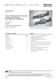
Pressure reducing valve,<br />
pilot operated<br />
Type DR<br />
Overview of contents<br />
Linear Motion and<br />
Assembly Technologies Pneumatics<br />
K 4661-5<br />
Nominal sizes 10 and 25<br />
DR 20 G-4-4X/..<br />
Series 4X<br />
Maximum operating pressure 315 bar<br />
Maximum flow 160 L/min<br />
Contents Page<br />
Features 1<br />
Ordering details 2<br />
Symbols 2<br />
Preferred types 2<br />
Function, section 3<br />
Technical data 4<br />
Characteristic curves 5<br />
Unit dimensions 6 to 8<br />
Service<br />
Automation<br />
Features<br />
Mobile<br />
Hydraulics<br />
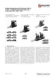
DR 20 K-5-1X/..<br />
– For subplate mounting:<br />
Porting pattern to DIN 24 340, Form D, ISO 5781<br />
and CETOP-RP 121 H,<br />
Subplates to catalogue sheet RE 45 062<br />
(separate order),<br />
– For threaded connections,<br />
– Cartridge version,<br />
– 4 adjustment elements:<br />
• Rotary knob<br />
• Sleeve with hexagon and protective cap<br />
• Lockable rotary knob with scale<br />
• Rotary knob with scale<br />
– 4 pressure stages<br />
© 2003<br />
by Bosch Rexroth AG, Industrial Hydraulics, D-97813 Lohr am Main<br />
All rights reserved. No part of this document may be reproduced or stored, processed, duplicated or circulated using<br />
electronic systems, in any form or by means, without the prior written authorisation of Bosch Rexroth AG. In the event<br />
of contravention of the above provisions, the contravening party is obliged to pay compensation.<br />
DR 1/8 RE <strong>26</strong> <strong>89</strong>3/02.03<br />
K 3444/6<br />
K3444/3<br />
DR 10-5-4X/..
Ordering details<br />
Nom. Subplate<br />
Valve for<br />
Version Version<br />
size mounting "G" "K"<br />
10 = 10<br />
Ordering details<br />
= 10 (G 1/2)<br />
= 15 (G 3/4)<br />
–<br />
25 = 20 = 20 (G 1) = 20<br />
For subplate mounting = No code<br />
For threaded connections = G<br />
For manifold mounting (cartridge)<br />
Adjustment element<br />
= K<br />
Rotary knob = 4<br />
Sleeve with hexagon and protective cap = 5<br />
Lockable rotary knob with scale = 6 1)<br />
Rotary knob with scale = 7<br />
1) Key with order no. R900008158<br />
is included within the scope of supply<br />
Symbols<br />
Preferred types (readily available)<br />
Type Material No<br />
DR 10-5-4X/100Y R900402741<br />
DR 10-5-4X/200Y R900402064<br />
DR 10-5-4X/315Y R900479797<br />
DR 10 G5-4X/100YM R900418436<br />
DR 10 G5-4X/315YM R900415481<br />
DR 20-5-4X/100Y R900404828<br />
DR 20-5-4X/200Y R900402753<br />
DR 20-5-4X/315Y R900405904<br />
DR 20 G5-4X/100YM R900417545<br />
DR 20 G5-4X/315YM R900493572<br />
DR – – / Y *<br />
Further details in clear text<br />
No code NBR seals<br />
V = FKM seals<br />
(other seals on request)<br />
Attention!<br />
The compatibility of the seals and pressure<br />
fluid has to be taken into account!<br />
No code = With check valve<br />
(only for the subplate mounting version)<br />
M = Without check valve<br />
50 = Settable pressure up to 50 bar<br />
100 = Settable pressure up to 100 bar<br />
200 = Settable pressure up to 200 bar<br />
315 = Settable pressure up to 315 bar<br />
1X = Series 10 to 19 (only version"K")<br />
(10 to 19: unchanged installation and connection dimensions)<br />
4X = Series 40 to 49<br />
(40 to 49: unchanged installation and connection dimensions)<br />
For subplate mounting For subplate mounting<br />
For threaded connections<br />
mounting<br />
as a cartridge valve<br />
connections<br />
B<br />
A<br />
Y<br />
Type DR...-4X/...Y Type DR...-4X/...YM<br />
Type DR...K.-1X/...YM<br />
(cartridge)<br />
B<br />
A Y B<br />
Type Material No<br />
DR 20 K5-1X/50YM R900474524<br />
DR 20 K5-1X/100YM R900474525<br />
DR 20 K5-1X/200YM R9004745<strong>26</strong><br />
DR 20 K5-1X/315YM R900474527<br />
Further preferred types and standard units can<br />
be found in the EPS (Standard Price List).<br />
RE <strong>26</strong> <strong>89</strong>3/02.03 2/8 DR<br />
A<br />
Y<br />
Type DR...G.-4X/...YM
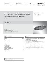
Function, section<br />
The pressure control valve type DR, series 4X, is a, cartridge<br />
version, pilot operated pressure reducing valve. It is used to reduce<br />
pressure in a system.<br />
The pressure reducing valve comprises of the cartridge and a<br />
housing, optionally with or without a check valve (only for the<br />
subplate mounting version).<br />
Pressure reducing valves types DR 10 and DR 20<br />
At rest the valve is open. The pressure fluid can pass unhindered<br />
from the inlet port via the main spool (1) to the outlet port. The<br />
pressure in the output port is applied via the drilling (2) onto the<br />
spring loaded side of the main spool assembly (1). At the same<br />
time the pressure acts on the spring at the opposite end of the<br />
main spool (1) via drillings (3) and (4).<br />
If the pressure in the output port rises above the value set at<br />
spring (6), then the pilot poppet (5) opens. Pressure fluid flows<br />
from the spring loaded side of the main spool (1) via orifice (7) and<br />
the pilot poppet (5) into the spring chamber (8).<br />
8 6 5 7 10 4 3 1<br />
9 Y A 2<br />
B<br />
The main spool (1) moves into its control position and maintains<br />
the value set at the spring (6) in the outlet port. Pilot oil return<br />
from the spring chamber (8) is always external via port Y (9).<br />
For the subplate mounting version an optional check valve (10) can<br />
be fitted to permit free-flow from port A to B.<br />
Remote control<br />
The types DR 10 and DR 20, series 4X, pressure reducing valves<br />
can only be remotely controlled via port Y.<br />
DR 3/8 RE <strong>26</strong> <strong>89</strong>3/02.03<br />
5<br />
7<br />
2<br />
A A<br />
B<br />
Y<br />
8<br />
6<br />
9<br />
4<br />
3<br />
1
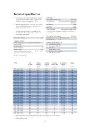
Technical data (for applications outside these parameters, please consult us!)<br />
General<br />
Installation Optional<br />
Ambient temperature range °C – 30 … + 80 with NBR seals<br />
°C – 20 … + 80 with FKM seals<br />
Nominal size NS 10 25<br />
Weight Subplate mounting kg 3.2 3.5<br />
Hydraulic<br />
Threaded connections kg 3.6 3.3<br />
Cartridge valve kg 2.5 2.8<br />
Nominal pressure bar 315<br />
Maximum operating pressure (inlet) bar 315<br />
Maximum secondary pressure (outlet) bar 50; 100; 200; 315<br />
Maximum back pressure in port Y bar 250<br />
Settable pressure Minimum bar Flow dependent (see characteristic curves on page 5)<br />
Maximum bar 50; 100; 200; 315<br />
Maximum flow Subplate mounting L/min 80 160<br />
Threaded connection L/min 80 160<br />
Pressure fluid Mineral oil (HL, HLP) to DIN 51 524 2) ;<br />
Fast bio-degradable pressure fluids to<br />
VDMA 24 568 (also see RE 90 221); HETG (rape seed oil) 1) ;<br />
HEPG (polyglycole) 2) ; HEES (Synthetic ester) 2) ;<br />
other pressure fluids on request<br />
Pressure fluid temperature range °C – 30 … + 80 with NBR seals<br />
°C – 20 … + 80 with FKM seals<br />
Viscosity range mm2 /s 10 … 800<br />
ISO code cleanliness class Maximum permissible degree of contamination of the pressure<br />
fluid is to ISO 4406 (C) class 20/18/15 3)<br />
1) Suitable for NBR and FKM seals<br />
2) Only suitable for FKM seals<br />
3) The cleanliness class stated for the components must be adhered too in hydraulic systems. Effective filtration prevents faults from<br />
occurring and at the same time increases the component service life.<br />
For the selection of filters see catalogue sheets RE 50 070, RE 50 076 and RE 50 081.<br />
RE <strong>26</strong> <strong>89</strong>3/02.03 4/8 DR
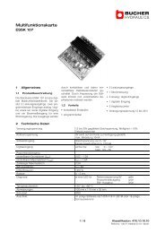
Characteristic curves (measured with HLP46, ϑ oil = 40 °C ± 5 °C)<br />
Outlet pressure in bar →<br />
Control flow in L/min →<br />
Min. pressure differential in bar →<br />
Pressure differential in bar →<br />
Outlet pressure pA in relationship to the<br />
flow qV (B to A)<br />
315<br />
250<br />
200<br />
150<br />
100<br />
14<br />
12<br />
10<br />
50<br />
1,50<br />
1,25<br />
1,0<br />
0,75<br />
0,50<br />
0,25<br />
0 20 40 60 80 100 120 140 160<br />
Flow in L/min →<br />
8<br />
6<br />
4<br />
2<br />
0 20 40 60 80 100 120 140 160<br />
Flow in L/min →<br />
7<br />
6<br />
5<br />
4<br />
3<br />
2<br />
1<br />
NG 10 NG 25<br />
0 20 40 60 80 100 120 140 160<br />
3<br />
NS NG 10 NG NS 25<br />
4<br />
Minimum settable pressure p A min<br />
related to the flow q V (B to A)<br />
Flow in L/min → Flow in L/min →<br />
NS NG 10 NS NG 25<br />
Dp= 250 bar<br />
Dp= 50 bar<br />
NS NG 10 NS NG 25<br />
0 20 40 60 80 100 120 140 160<br />
Outlet pressure in bar →<br />
30<br />
25<br />
20<br />
15<br />
10<br />
5<br />
NG 10 NG 25<br />
0 20 40 60 80 100 120 140 160<br />
Control flow q V st in relationship to the flow q V (B to A) and to the pressure differential ∆p<br />
∆p min -q V - characteristic curves (B to A)<br />
∆p min -q V - characteristic curves (B to A)<br />
Flow in L/min →<br />
DR 5/8 RE <strong>26</strong> <strong>89</strong>3/02.03<br />
1<br />
5<br />
6<br />
2<br />
Performance limit<br />
(dependent on the<br />
system):<br />
1 NS 10<br />
2 NS 25<br />
3 and 4 NS 10<br />
5 and 6 NS 25<br />
3 and 5:<br />
Main stage closed<br />
4 and 6:<br />
Main stage fully open
Unit dimensions: for subplate mounting (dimensions in mm)<br />
Ø 32<br />
8 4 3 11<br />
18<br />
2109 8<br />
1 Adjustment element “4”<br />
2 Adjustment element “5”<br />
3 Adjustment element “6”<br />
4 Adjustment element “7”<br />
5 Locknut 22A/F<br />
6 Hexagon 10A/F<br />
7 Hexagon 30A/F<br />
tightening torque<br />
MA = 50 Nm<br />
8 Space required to remove the key<br />
9 Locating pin<br />
10 Valve fixing screw holes<br />
11 Name plate<br />
12 Identical seal rings for ports A and B<br />
13 Seal ring for port Y<br />
Subplates to catalogue sheet RE 45 062<br />
and valve fixing screws<br />
must be ordered separately.<br />
Subplates for<br />
Valve size 10:<br />
G 460/01 (G 3/8)<br />
G 461/01 (G 1/2)<br />
Valve size 20:<br />
G 412/01 (G 3/4)<br />
G 413/01 (G 1)<br />
Valve fixing screws for<br />
Valve size 10:<br />
M10 x 40 DIN 912–10.9, MA = 75 Nm<br />
Valve size 20:<br />
M10 x 50 DIN 912–10.9, MA = 75 Nm<br />
3<br />
76<br />
Ø<br />
100<br />
40<br />
6 2 1 5 7 9 13 12<br />
B1<br />
B2<br />
Ø 30<br />
H4<br />
Required surface finish of the<br />
mating piece<br />
0,01/100mm<br />
R max 4<br />
RE <strong>26</strong> <strong>89</strong>3/02.03 6/8 DR<br />
48<br />
L5<br />
ØD2<br />
ØD3<br />
48<br />
L1<br />
ØD1<br />
A<br />
L6<br />
L4 L3<br />
L2<br />
B<br />
Ø6<br />
Ø17,2<br />
Ø8<br />
Valve type L1 L2 L3 L4 L5 L6 B1 B2 B3 B4 H1 H2<br />
DR 10 95.5 79 42.9 23 2.5 21.5 85 49 66.7 7.9 71 60<br />
DR 20 96 79.5 60.3 7 4 39.7 100 58 79.4 6.4 96 78<br />
Valve type H3 H4 Ø D1 Ø D2 Ø D3<br />
DR 10 <strong>26</strong> <strong>26</strong> 35.5 21.8 15<br />
DR 20 <strong>26</strong> 40 41 34.8 25<br />
H3<br />
5<br />
B4<br />
H2<br />
4xØ11<br />
B3<br />
H1 5<br />
10
Unit dimensions: for threaded connections (dimensions in mm)<br />
10<br />
Attention!<br />
This valve version does<br />
not include an<br />
integrated check valve<br />
for free return flow.<br />
90<br />
41 45<br />
66<br />
=<br />
=<br />
Valve type D1 Ø D2<br />
DR 10 G G 1/2 34<br />
DR 15 G G 3/4 42<br />
DR 20 G G 1 47<br />
1 Adjustment element “4”<br />
2 Adjustment element “5”<br />
3 Adjustment element “6”<br />
4 Adjustment element “7”<br />
48<br />
Ø9<br />
ØD2; 0,3<br />
D1<br />
ØD2; 0,3<br />
B<br />
ØD2; 0,3<br />
44,5<br />
121<br />
A<br />
66<br />
45<br />
Ø25<br />
D1<br />
DR 7/8 RE <strong>26</strong> <strong>89</strong>3/02.03<br />
Y<br />
A<br />
35 31 D1<br />
5 Locknut 22A/F<br />
6 Hexagon 10A/F<br />
7 Hexagon 30A/F<br />
tightening torque<br />
MA = 50 Nm<br />
G 1/4; 12<br />
40<br />
48<br />
3<br />
76<br />
8 9 0 1 2<br />
33<br />
Ø 30<br />
Ø 35<br />
74<br />
100 18<br />
Ø 32<br />
5<br />
1<br />
7<br />
14<br />
11<br />
8 Space required to remove the key<br />
10 Valve fixing screw holes<br />
11 Name plate<br />
14 Port Y for pilot oil drain<br />
2<br />
6<br />
4<br />
8<br />
3
Unit dimensions: for manifold mounting (dimensions in mm)<br />
4<br />
16<br />
17<br />
16<br />
76<br />
Ø 32<br />
2 1 0 9<br />
1 Adjustment element “4”<br />
2 Adjustment element “5”<br />
3 Adjustment element “6”<br />
4 Adjustment element “7”<br />
5 Locknut 22A/F<br />
6 Hexagon 10A/F<br />
7 Hexagon 30A/F<br />
tightening torque MA = 50 Nm<br />
8 Space required to remove the<br />
key<br />
16 Seal ring<br />
17 Back-up ring<br />
18 Depth of fit<br />
19 Connection bores A, B and Y<br />
positioned as required around<br />
circumference<br />
3<br />
Bosch Rexroth AG<br />
Industrial Hydraulics<br />
D-97813 Lohr am Main<br />
Zum Eisengießer 1 • D-97816 Lohr am Main<br />
Telefon 0 93 52 / 18-0<br />
Telefax 0 93 52 / 18-23 58 • Telex 6 <strong>89</strong> 418-0<br />
eMail documentation@boschrexroth.de<br />
Internet www.boschrexroth.de<br />
8<br />
100 18<br />
84<br />
8<br />
3<br />
0,02 A<br />
84±0,2<br />
6<br />
18<br />
66<br />
16,5<br />
64,5<br />
42<br />
12<br />
18<br />
max. Ø12<br />
max. Ø12<br />
Ø 35<br />
19<br />
Y = Rz<br />
Ø4<br />
40<br />
0,03 B<br />
Y<br />
A<br />
Bosch Rexroth Limited<br />
Cromwell Road, St Neots<br />
Cambs, PE19 2ES<br />
Tel: 0 14 80/22 32 56<br />
Fax: 0 14 80/21 90 52<br />
E-mail: info@boschrexroth.co.uk<br />
Z<br />
The data specified above only serves to describe<br />
the product. No statements concerning a certain<br />
condition or suitability for a certain application can<br />
be derived from our information. The details stated<br />
do not release you from the responsibility for<br />
carrying out your own assessment and verification.<br />
It must be remembered that our products are<br />
subject to a natural process of wear and ageing.<br />
RE <strong>26</strong> <strong>89</strong>3/02.03 8/8 DR<br />
Ø 30<br />
2 5 1<br />
B<br />
Z = Rz1<br />
Cavity<br />
7<br />
M28x1,5<br />
48<br />
Ø29 H8 20°<br />
Ø<strong>26</strong>,5<br />
Ø24 +0,1<br />
Z<br />
Ø22,5 H8<br />
Ø30<br />
Ø8<br />
Z<br />
20°<br />
20°<br />
Ø20,8 +0,2<br />
Ø21 H8<br />
Ø28<br />
Y<br />
Y<br />
Z<br />
A<br />
Z<br />
10°<br />
2,5<br />
8<br />
19<br />
28,5 +0,2<br />
35 +0,2<br />
0,03 A<br />
56 +0,2<br />
0,03 A