IBM 5150 PC Technical Reference (6025005, August, 1981) (PDF)
IBM 5150 PC Technical Reference (6025005, August, 1981) (PDF) IBM 5150 PC Technical Reference (6025005, August, 1981) (PDF)
Color selection is determined by the following logic: C 1 and CO will select 4 of 16 preselected colors. This color selection (palette) is preloaded in an I/O port. CI CO CODE SELECT COLOR FOR DISPLAY o 0 POSITION DOT TAKES ON COLOR OF 1 OF 16 o 1 PRESELECTED BACKGROUND COLORS. SELECT 1ST COLOR OF PRESELECT COLOR SET"I" OR "2" 1 0 SELECT 2ND COLOR OF PRESELECT COLOR SET "I" OR "2" 1 1 SELECT 3RD COLOR OF PRESELECT COLOR SET"1" OR "2" The two color sets are: SET ONE COLOR 1 - CYAN COLOR 2 - MAGENTA COLOR 3 - WHITE SET TWO COLOR I - GREEN COLOR 2 - RED COLOR 3- BROWN The background colors are the same basic 8 color as defined for low resolution graphic plus 8 alternate intensities defined by the intensity bit for a total of 16 color including black and white. 3. Black and white high resolution graphics (monitor) • Up to 200 rows of 640 pels each (IxI) • Black and white only • Requires 16000 bytes of Read/Write Memory (on the adapter) • Addressing and mapping is the same as for medium resolution color graphics, but the data format is different. In this mode each bit in memory is mapped to a pelon the screen. • 8 pels/byte 76543210 I I I I I I I I L H"t d',pl,y p,' " , by" 2-53
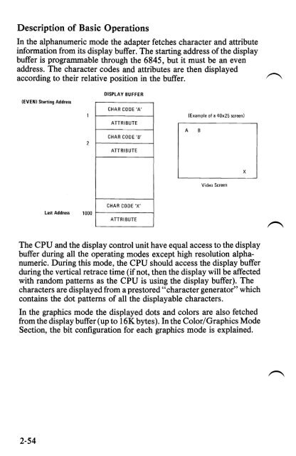
Description of Basic Operations In the alphanumeric mode the adapter fetches character and attribute information from its display buffer. The starting address of the display buffer is programmable through the 6845, but it must be an even address. The character codes and attributes are then displayed according to their relative position in the buffer. (EVEN) Starting Address DISPLAY BUFFER CHAR CODE 'A' ATTRIBUTE CHAR CODE 'B' A (Example of a 40x25 screen) B ATTRIBUTE Video Screen X Last Address 1000 CHAR CODE 'X' ATTRIBUTE The CPU and the display control unit have equal access to the display buffer during all the operating modes except high resolution alphanumeric. During this mode, the CPU should access the display buffer during the vertical retrace time (if not, then the display will be affected with random patterns as the CPU is using the display buffer). The characters are displayed from a prestored "character generator" which contains the dot patterns of all the displayable characters. In the graphics mode the displayed dots and colors are also fetched from the display buffer (up to 16K bytes). In the Color/Graphics Mode Section, the bit configuration for each graphics mode is explained. 2-54
- Page 22 and 23: SYSTEM BOARD The System Board fits
- Page 24 and 25: The memory is dynamic 16K x 1 chips
- Page 26 and 27: System Board Data Flow Figure 2. S
- Page 28 and 29: 1/0 Channel Diagram REAR PANEl SI
- Page 30 and 31: I/O CHRDY I I/O Channel Ready: This
- Page 32 and 33: System Board Component Diagram REA
- Page 34 and 35: Keyboard Interface B lock Diagram
- Page 36 and 37: 1 2 3 4 5 6 7 8 9 10 11 12 13 14 15
- Page 38 and 39: Cassette User Interface The cassett
- Page 40 and 41: Cassette Interface Connector Specif
- Page 42 and 43: I/O Address Map HEX RANGE 9 8 7 6
- Page 44 and 45: System Memory Map X'OOOOO' 16 TO 6
- Page 46 and 47: System Memory Map Cont. START ADDR
- Page 48 and 49: 5-1/4" Diskette Drives Switch Setti
- Page 50 and 51: 32/64KB Memory Expansion Option Sw
- Page 52 and 53: Power Supply The system DC power su
- Page 54 and 55: N I ~ VI ) § I • \. ~ o el so.
- Page 56 and 57: IBM Monochrome Display and Parallel
- Page 58 and 59: System Channel Interface Lines Used
- Page 60 and 61: Programming Considerations Programm
- Page 62 and 63: • CRT Status Port (I/O Address '3
- Page 64 and 65: Color/Graphics Monitor Adapter The
- Page 66 and 67: CPU .. r-- ) ) ) DISPLAY ADDRESS BU
- Page 68 and 69: Modes of Operation There are two ba
- Page 70 and 71: IBM Monochrome Display Adapter V s.
- Page 74 and 75: 1"'"""""\ Table 5. I R G B Summary
- Page 76 and 77: Programming the Mode Control and St
- Page 78 and 79: Bit 5 When on, this bit will change
- Page 80 and 81: I/O Address and Bit Map Read/Write
- Page 82 and 83: Color/Graphics Monitor Adapter Auxi
- Page 84 and 85: Parallel Printer Adapter The Printe
- Page 86 and 87: Programming Considerations The Prin
- Page 88 and 89: Parallel Printer Adapter Interface
- Page 90 and 91: Table 7. Printer Specifications (1
- Page 92 and 93: Table 9. Functions and Conditions o
- Page 94 and 95: Table 10. Connector Pin Assignment
- Page 96 and 97: (4) Data transfer sequence Fig. 17
- Page 98 and 99: ASCII Control Codes Control Codes V
- Page 100 and 101: (8) DC 2 (Device Control 2) The DC
- Page 102 and 103: (b) 3) ESC 2 (Escape 2) Receipt of
- Page 104 and 105: ehaves like the LF code. Therefore,
- Page 106 and 107: [DATA] IESCGI ABCDEFGHI [PRINT] ABC
- Page 108 and 109: 5 1/4-Inch Diskette Drive Adapter T
- Page 110 and 111: ~ Functional Description From a pro
- Page 112 and 113: The FOe is capable of performing 15
- Page 114 and 115: Table 13. Symbol Descriptions (cont
- Page 116 and 117: Command Summary (continued) DATA B
- Page 118 and 119: Command Summary (continued) DATA B
- Page 120 and 121: Table 15. Status Register I BIT NO.
Description of Basic Operations<br />
In the alphanumeric mode the adapter fetches character and attribute<br />
information from its display buffer. The starting address of the display<br />
buffer is programmable through the 6845, but it must be an even<br />
address. The character codes and attributes are then displayed<br />
according to their relative position in the buffer.<br />
(EVEN) Starting Address <br />
DISPLAY BUFFER <br />
CHAR CODE 'A'<br />
ATTRIBUTE<br />
CHAR CODE 'B'<br />
A<br />
(Example of a 40x25 screen)<br />
B<br />
ATTRIBUTE<br />
Video Screen<br />
X<br />
Last Address 1000<br />
CHAR CODE 'X'<br />
ATTRIBUTE<br />
The CPU and the display control unit have equal access to the display<br />
buffer during all the operating modes except high resolution alphanumeric.<br />
During this mode, the CPU should access the display buffer<br />
during the vertical retrace time (if not, then the display will be affected<br />
with random patterns as the CPU is using the display buffer). The<br />
characters are displayed from a prestored "character generator" which<br />
contains the dot patterns of all the displayable characters.<br />
In the graphics mode the displayed dots and colors are also fetched<br />
from the display buffer (up to 16K bytes). In the Color/Graphics Mode<br />
Section, the bit configuration for each graphics mode is explained.<br />
2-54


