IBM 5150 PC Technical Reference (6025005, August, 1981) (PDF)
IBM 5150 PC Technical Reference (6025005, August, 1981) (PDF) IBM 5150 PC Technical Reference (6025005, August, 1981) (PDF)
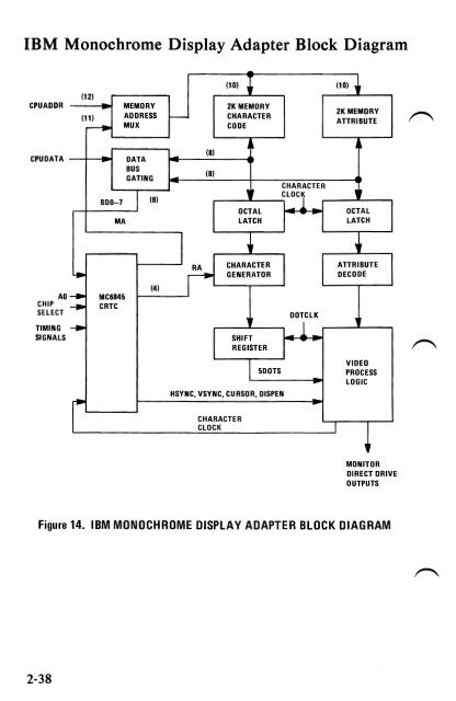
IBM Monochrome Display and Parallel Printer Adapter This adapter has dual functions. The first is to provide the interface to the IBM Monochrome Display. The second function is a parallel ,~interface for the IBM 80 CPS Matrix Printer. The monitor interface is designed around the Motorola 6845 CRT Controller module. There are 4K bytes of static memory on the card which are used for the display buffer. The memory is dual ported and may be accessed directly by the CPU. No parity is provided on the display buffer. A block diagram of the Monochrome Display function in on page 2-38. The characteristics of the design are listed below: • 80x25 Screen • Direct Drive Output • 9x14 Character Box • 7x9 Character • 18 Khz Monitor • Character Attributes ~ The adapter supports 256 character codes. An 8K byte character generator contains the fonts for the character codes. The characters, values, keystrokes and screen characteristics are tabled in Appendix C. Of Characters, Keystrokes and Color. Note: This Adapter when used with a display containing P39 Phospor, will not support a light pen! Parallel Interface Description This topic is discussed in full on pages 2-65 through page 2-69. 2-37
IBM Monochrome Display Adapter Block Diagram - (10) (10) • (12) CPUADDR MEMORY 2K MEMORY (11) ADDRESS ,...- CHARACTER ,--. MUX CODE 2KMEMORY ATTRIBUTE CPUDATA BDO-7 DATA BUS GATING - (8) (8) , CHARACTER (8) ~LOCI OCTAL r .Ir OCTAL MA LATCH LATCH 1 ~ ~ RA CHARACTER ATTRIBUTE ~ GENERATOR DECODE AD ~ MC6845 CHIP ~ CRTC (4) SELECT DOTCLK , TIMING ~ SIGNALS SHIFT REGISTER I 1 SDOTS r HSYNC, VSYNC, CURSOR, DISPEN . CHARACTER CLOCK I VIDEO PROCESS LOGIC ~ MONITOR DIRECT DRIVE OUTPUTS Figure 14. IBM MONOCHROME DISPLAY ADAPTER BLOCK DIAGRAM 2-38
- Page 5 and 6: FEDERAL COMMUNICATIONS COMMISSION R
- Page 8 and 9: CONTENTS SECTION 1. HARDWARE OVERV
- Page 10 and 11: Programming Considerations ........
- Page 12 and 13: INS 8250 Functional Pin Description
- Page 14 and 15: FIGURE LISTING 1. System Block Dia
- Page 16 and 17: SECTION I. HARDWARE OVERVIEW The
- Page 18 and 19: The 16KB Memory Expansion Kits allo
- Page 20 and 21: SECTION 2. HARDWARE ~ Contents: Sys
- Page 22 and 23: SYSTEM BOARD The System Board fits
- Page 24 and 25: The memory is dynamic 16K x 1 chips
- Page 26 and 27: System Board Data Flow Figure 2. S
- Page 28 and 29: 1/0 Channel Diagram REAR PANEl SI
- Page 30 and 31: I/O CHRDY I I/O Channel Ready: This
- Page 32 and 33: System Board Component Diagram REA
- Page 34 and 35: Keyboard Interface B lock Diagram
- Page 36 and 37: 1 2 3 4 5 6 7 8 9 10 11 12 13 14 15
- Page 38 and 39: Cassette User Interface The cassett
- Page 40 and 41: Cassette Interface Connector Specif
- Page 42 and 43: I/O Address Map HEX RANGE 9 8 7 6
- Page 44 and 45: System Memory Map X'OOOOO' 16 TO 6
- Page 46 and 47: System Memory Map Cont. START ADDR
- Page 48 and 49: 5-1/4" Diskette Drives Switch Setti
- Page 50 and 51: 32/64KB Memory Expansion Option Sw
- Page 52 and 53: Power Supply The system DC power su
- Page 54 and 55: N I ~ VI ) § I • \. ~ o el so.
- Page 58 and 59: System Channel Interface Lines Used
- Page 60 and 61: Programming Considerations Programm
- Page 62 and 63: • CRT Status Port (I/O Address '3
- Page 64 and 65: Color/Graphics Monitor Adapter The
- Page 66 and 67: CPU .. r-- ) ) ) DISPLAY ADDRESS BU
- Page 68 and 69: Modes of Operation There are two ba
- Page 70 and 71: IBM Monochrome Display Adapter V s.
- Page 72 and 73: Color selection is determined by th
- Page 74 and 75: 1"'"""""\ Table 5. I R G B Summary
- Page 76 and 77: Programming the Mode Control and St
- Page 78 and 79: Bit 5 When on, this bit will change
- Page 80 and 81: I/O Address and Bit Map Read/Write
- Page 82 and 83: Color/Graphics Monitor Adapter Auxi
- Page 84 and 85: Parallel Printer Adapter The Printe
- Page 86 and 87: Programming Considerations The Prin
- Page 88 and 89: Parallel Printer Adapter Interface
- Page 90 and 91: Table 7. Printer Specifications (1
- Page 92 and 93: Table 9. Functions and Conditions o
- Page 94 and 95: Table 10. Connector Pin Assignment
- Page 96 and 97: (4) Data transfer sequence Fig. 17
- Page 98 and 99: ASCII Control Codes Control Codes V
- Page 100 and 101: (8) DC 2 (Device Control 2) The DC
- Page 102 and 103: (b) 3) ESC 2 (Escape 2) Receipt of
- Page 104 and 105: ehaves like the LF code. Therefore,
<strong>IBM</strong> Monochrome Display Adapter Block Diagram <br />
-<br />
(10) (10) •<br />
(12)<br />
CPUADDR MEMORY 2K MEMORY<br />
(11) ADDRESS ,...- CHARACTER<br />
,--. MUX CODE<br />
2KMEMORY<br />
ATTRIBUTE<br />
CPUDATA<br />
BDO-7<br />
DATA<br />
BUS<br />
GATING<br />
-<br />
(8)<br />
(8)<br />
,<br />
CHARACTER<br />
(8) ~LOCI<br />
OCTAL<br />
r<br />
.Ir<br />
OCTAL<br />
MA LATCH LATCH<br />
1 ~ ~<br />
RA CHARACTER<br />
ATTRIBUTE<br />
~ GENERATOR DECODE<br />
AD ~ MC6845 <br />
CHIP <br />
~ CRTC<br />
(4)<br />
SELECT DOTCLK , <br />
TIMING ~ <br />
SIGNALS<br />
SHIFT <br />
REGISTER <br />
I 1<br />
SDOTS<br />
r<br />
HSYNC, VSYNC, CURSOR, DISPEN<br />
.<br />
CHARACTER<br />
CLOCK<br />
I<br />
VIDEO<br />
PROCESS<br />
LOGIC<br />
~<br />
MONITOR<br />
DIRECT DRIVE<br />
OUTPUTS<br />
Figure 14. <strong>IBM</strong> MONOCHROME DISPLAY ADAPTER BLOCK DIAGRAM<br />
2-38


