Microstructure Analysis on Nanocrystalline Materials COMMISSION ...
Microstructure Analysis on Nanocrystalline Materials COMMISSION ...
Microstructure Analysis on Nanocrystalline Materials COMMISSION ...

You also want an ePaper? Increase the reach of your titles
YUMPU automatically turns print PDFs into web optimized ePapers that Google loves.
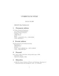
of neighbouring crystallites disappears completely. In<br />
this angular range, the diffracti<strong>on</strong> line broadening remains<br />
c<strong>on</strong>stant, being approximately equal to the reciprocal<br />
size of individual (n<strong>on</strong>-coherent) crystallites.<br />
Intensity (arb.units)<br />
1.8<br />
1.6<br />
1.4<br />
1.2<br />
1.0<br />
0.8<br />
0.6<br />
0.4<br />
0.2<br />
0.0<br />
-0.2 -0.1 0.0 0.1 0.2<br />
Δq z (Å -1 )<br />
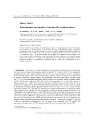
Fig. 5. Diffracti<strong>on</strong> profiles calculated using equati<strong>on</strong>s<br />
(17), (18) and (19) for incoherent, partially coherent<br />
and fully coherent crystallites (from the top to the bottom).<br />
The displacement of the reciprocal lattice points<br />
is the same like in Figures 4, 3 and 2, respectively.<br />
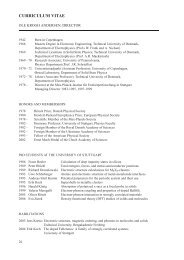
Line broadening (Å -1 )<br />
0.014<br />
0.012<br />
0.010<br />
0.008<br />
0.006<br />
0.004<br />
D = 80 Å<br />
ω = 2.3° ω = 1.2° ω = 0.8°<br />
0.002<br />
0.0 0.2 0.4 0.6 0.8 1.0<br />
sin θ<br />
Fig. 6. Diffracti<strong>on</strong> line broadening as calculated according<br />
to Ref. [6] for partially coherent crystallites<br />
with the size of 80 Å and with the disorientati<strong>on</strong> of 0.8°,<br />
1.2° and 2.3°. Small oscillati<strong>on</strong>s in the range of the in-<br />
creasing line broadening are due to the numerical errors.<br />
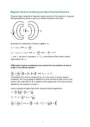
Line broadening (Å -1 )<br />
0.020<br />
0.016<br />
0.012<br />
0.008<br />
0.004<br />
0.000<br />
0.0 0.2 0.4 0.6 0.8 1.0<br />
sin θ<br />
Fig. 7. Diffracti<strong>on</strong> line broadening as calculated according<br />
to equati<strong>on</strong>s (17), (18) and (19) for partially<br />
coherent crystallites with the size of 50 Å and with the<br />
disorientati<strong>on</strong> of 1.0° (triangles), 1.5° (circles) and<br />
2.5° (boxes).<br />
An analogous dependence of the diffracti<strong>on</strong> line broadening<br />
<strong>on</strong> the diffracti<strong>on</strong> angle can also be derived using<br />
the approach described in the previous Secti<strong>on</strong>. The<br />
line broadening shown in Fig. 7 was obtained from fitting<br />
the diffracti<strong>on</strong> profiles calculated using equati<strong>on</strong>s<br />
(17), (18) and (19) by the Pears<strong>on</strong> VII functi<strong>on</strong>. Some<br />
examples of the line profile fitting are shown in Fig. 5.<br />
In both approaches discussed above, the minimum and<br />
the maximum diffracti<strong>on</strong> line broadening corresp<strong>on</strong>d to<br />
the size of clusters of partially coherent crystallites and<br />
to the size of n<strong>on</strong>-coherent crystallites, respectively.<br />
The main difference between these approaches is the<br />
steepness of the increase of the diffracti<strong>on</strong> line broadening<br />
with increasing diffracti<strong>on</strong> angle. The microstructural<br />
model described in [6] assumes a c<strong>on</strong>tinuous<br />
distributi<strong>on</strong> of the disorientati<strong>on</strong>s of neighbouring crystallites<br />
between zero and a maximum disorientati<strong>on</strong>,<br />
which increases the degree of the coherence in the<br />
middle range of the diffracti<strong>on</strong> angles and shifts the<br />
steep increase of the diffracti<strong>on</strong> line broadening to larger<br />
diffracti<strong>on</strong> angles. C<strong>on</strong>sequently, the higher degree<br />
of the partial coherence of crystallites in the middle<br />
range of the diffracti<strong>on</strong> angles causes a steeper increase<br />
of the diffracti<strong>on</strong> line broadening at larger diffracti<strong>on</strong><br />
angles. The other microstructural model, which was<br />
used for the approach described in the previous Secti<strong>on</strong>,<br />
assumes a c<strong>on</strong>stant disorientati<strong>on</strong> of neighbouring<br />
crystallites in the clusters of partially coherent crystallites,<br />
which leads to a gradual decay of the partial coherence<br />
of crystallites that is dem<strong>on</strong>strated by a slower<br />
increase of the diffracti<strong>on</strong> line broadening with increas-<br />
10