Axial Piston Pumps Technical Information Series 40
Axial Piston Pumps Technical Information Series 40 Axial Piston Pumps Technical Information Series 40
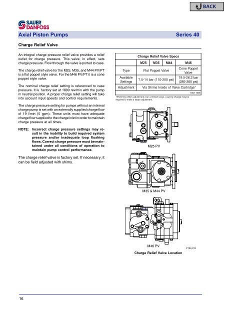
Axial Piston Pumps Series 40 Charge Relief Valve An integral charge pressure relief valve provides a relief outlet for charge pressure. This valve, in effect, sets charge pressure. Flow through the valve is ported to case. The charge relief valve for the M25, M35, and M44 PV/PT is a flat poppet style valve. For the M46 PV/PT it is a cone poppet style valve. The nominal charge relief setting is referenced to case pressure. It is factory set at 1800 rev/min with the pump in neutral position. A proper charge relief setting will take into account input speeds and control requirements. Type Available Settings Charge Relief Valve Specs M25 M35 M44 M46 Flat Poppet Valve 7.5-14 bar (110-200 psi) Cone Poppet Valve 19.5-26.2 bar (285-380 psi) A djustment Via Shims Inside of Valve Cartridge* *Shimming offers adjustment over a limited range, a spring change may be required to make a larger adjustment. T002 160E The charge pressure setting for pumps without an internal charge pump is set with an externally supplied charge flow of 19 l/min (5 gpm). These units must have adequate charge flow supplied to the charge inlet in order to maintain charge pressure at all times. NOTE: Incorrect charge pressure settings may result in the inability to build required system pressure and/or inadequate loop flushing flows. Correct charge pressure must be maintained under all conditions of operation to maintain pump control performance. M25 PV The charge relief valve is factory set. If necessary, it can be field adjusted with shims. M35 & M44 PV M46 PV Charge Relief Valve Location P100 312 16
Axial Piston Pumps Series 40 Check / High Pressure Relief Valves Circuit pressure is maintained in the proper range by the combination charge check and high pressure relief valves. The check valves allow charge flow to replenish the low pressure side of the working loop. The high pressure relief valves provide pressure protection to the high pressure side of the working loop. There are two cartridge style valves to handle each side of the working loop with flow in either direction. Check / High Pressure Relief Valves Specs Type Cartridge-style poppet valve S ettings 140-345 bar (2030-5000 psi) Option Check only - no relief valve T002 161E High pressure relief valves are available in a range of settings. Individual port pressure settings may be specified. Pumps may be equipped with charge circuit check valves only, if high pressure relief valves are not desired. NOTE: High pressure relief valves are intended for transient overpressure protection and are not intended for continuous pressure control. Operation over relief valves for extended periods of time may result in severe heat build up. High flows over relief valves may result in pressure levels exceeding the nominal valve setting and potential damage to system components. M25 PV Bypass Valves In some applications it is desirable to bypass fluid around the variable displacement pump allowing, for example, a vehicle to be moved short distances at low speeds without running the prime mover. This is accomplished by a manually operated bypass valve. When open, this valve connects both sides of the pump/motor circuit and allows the motor to turn. This valve must be fully closed for normal operation. Bypass Valve M35 & M44 PV M25, M35, & M44: Bypass valves on the M25, M35, and M44 PV and PT are integral with the check relief valve assemblies. Both assemblies must be opened for bypass operation. Valves are fully open at 4 revolutions. Do not open valves past 4 turns. Plug torque is 41 to 95 Nm (30 to 70 ft•lbf). M46: The bypass valve(s) on the M46 PV or PT is fully open at 2 revolutions of the valve stem. Do not open valve past 2 turns. Valve closing torque is 9.5 to 14 Nm (7 to 10 ft•lbf). Damage to units may result from overtorquing the bypass valve. NOTE: Operate bypass valve only at low speeds for short periods. The motor speed should not surpass 400 rev/min. As a rule of thumb, vehicle applications should be "towed" at less than 10% of typical operating speed. Type Max Motor "Tow" Speed Full Open At M46 PV Check / High Pressure Relief / Bypass Valves Location Bypass Valve Specs M25 M35 M44 M46 Incorporated in 2 Check/Relief Valves 400 rev/min Dedicated Needle Valve 4 turns 2 turns P100 313E T002 162E 17
- Page 1 and 2: Series 40 Axial Piston Pumps Techni
- Page 3 and 4: Axial Piston Pumps Series 40 Conten
- Page 5 and 6: Axial Piston Pumps Series 40 System
- Page 7 and 8: Axial Piston Pumps Series 40 System
- Page 9 and 10: Axial Piston Pumps Series 40 Hydrau
- Page 11 and 12: Axial Piston Pumps Series 40 Inlet
- Page 13 and 14: Axial Piston Pumps Series 40 Suctio
- Page 15: Axial Piston Pumps Series 40 System
- Page 19 and 20: Axial Piston Pumps Series 40 Shaft
- Page 21 and 22: Axial Piston Pumps Series 40 Mounti
- Page 23 and 24: Axial Piston Pumps Series 40 Hydrau
- Page 25 and 26: Axial Piston Pumps Series 40 Direct
- Page 27 and 28: Axial Piston Pumps Series 40 A rang
- Page 29 and 30: Axial Piston Pumps Series 40 Respon
- Page 31 and 32: Axial Piston Pumps Series 40 Respon
- Page 33 and 34: Axial Piston Pumps Series 40 Respon
- Page 35 and 36: Axial Piston Pumps Series 40 M25 PV
- Page 37 and 38: Axial Piston Pumps Series 40 M25 PT
- Page 39 and 40: Axial Piston Pumps Series 40 Notes
- Page 41 and 42: Axial Piston Pumps Series 40 M35/44
- Page 43 and 44: Axial Piston Pumps Series 40 M35/44
- Page 45 and 46: Axial Piston Pumps Series 40 M46 PV
- Page 47 and 48: Axial Piston Pumps Series 40 M46 PT
- Page 49 and 50: Axial Piston Pumps Series 40 M46 PV
- Page 51 and 52: Axial Piston Pumps Series 40 M46 PV
- Page 53 and 54: Axial Piston Pumps Series 40 Series
- Page 55 and 56: Axial Piston Pumps Series 40 Notes
<strong>Axial</strong> <strong>Piston</strong> <strong>Pumps</strong> <strong>Series</strong> <strong>40</strong><br />
Charge Relief Valve<br />
An integral charge pressure relief valve provides a relief<br />
outlet for charge pressure. This valve, in effect, sets<br />
charge pressure. Flow through the valve is ported to case.<br />
The charge relief valve for the M25, M35, and M44 PV/PT<br />
is a flat poppet style valve. For the M46 PV/PT it is a cone<br />
poppet style valve.<br />
The nominal charge relief setting is referenced to case<br />
pressure. It is factory set at 1800 rev/min with the pump<br />
in neutral position. A proper charge relief setting will take<br />
into account input speeds and control requirements.<br />
Type<br />
Available<br />
Settings<br />
Charge Relief Valve Specs<br />
M25<br />
M35<br />
M44<br />
M46<br />
Flat Poppet Valve<br />
7.5-14 bar (110-200 psi)<br />
Cone Poppet<br />
Valve<br />
19.5-26.2 bar<br />
(285-380 psi)<br />
A djustment Via Shims Inside of Valve Cartridge*<br />
*Shimming offers adjustment over a limited range, a spring change may be<br />
required to make a larger adjustment.<br />
T002 160E<br />
The charge pressure setting for pumps without an internal<br />
charge pump is set with an externally supplied charge flow<br />
of 19 l/min (5 gpm). These units must have adequate<br />
charge flow supplied to the charge inlet in order to maintain<br />
charge pressure at all times.<br />
NOTE:<br />
Incorrect charge pressure settings may result<br />
in the inability to build required system<br />
pressure and/or inadequate loop flushing<br />
flows. Correct charge pressure must be maintained<br />
under all conditions of operation to<br />
maintain pump control performance.<br />
M25 PV<br />
The charge relief valve is factory set. If necessary, it<br />
can be field adjusted with shims.<br />
M35 & M44 PV<br />
M46 PV<br />
Charge Relief Valve Location<br />
P100 312<br />
16


