Data sheet BIDP170 M - Balogh technical center
Data sheet BIDP170 M - Balogh technical center
Data sheet BIDP170 M - Balogh technical center

You also want an ePaper? Increase the reach of your titles
YUMPU automatically turns print PDFs into web optimized ePapers that Google loves.
Network Interface Card<br />
189, rue d'Aubervilliers CP 97 75886 PARIS Cedex18 France<br />
33 (0)1.44.65.65.00 http://www.balogh-group.com<br />
33 (0)1.44.65.65.10 balogh.sales@balogh-group.com<br />
BIDP 170M<br />
IDENTIFICATION SYSTEMS<br />
REFERENCES ———————————–——————–——————————————————————-———————————————–—<br />
Generic references: <strong>BIDP170</strong>M## for 2 channels.<br />
Depending on the tag the card can exchange data with on the corresponding channel a specific firmware is implemented;<br />
it is defined by the suffix #, e.g. <strong>BIDP170</strong>MAA is designed for OMA tags reading/writing on both channels.<br />
GENERAL FEATURES ——————————–———————–———————————————————-———————–———–—<br />
Authorized slave interface for ProfiBus® DP-V1 (Ident-Number = 08E9HEX).<br />
It handles up to two independent R/W channels (both simultaneously read / write data from / to <strong>Balogh</strong> tags); the<br />
channels may differ from each other in tags type.<br />
Communications occur over an RS-485 link (twisted shielded pair).<br />
Each BIDP is assumed as a I/O module exchanging data with a class-1 master:<br />
• in acyclic mode, it receives requests and retrieves / sends the tag data (up to 16 Kbytes per request),<br />
• in cyclic mode, it transmits both channel statuses.<br />
It It is driven by the FS-S7M functional block for a Siemens Series-7 PLC type 3xx ou 4xx (Step 7 ® shell).<br />
The functional block is delivered on a CD.<br />
DATA FOR ASSEMBLY ——————————–———————–———————————————————-———————–———<br />
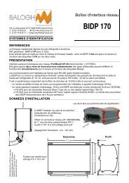
view of the upper flange bearing the indicator lights:<br />
Field mount enclosure.<br />
Vertical mounting preferable,<br />
connectors flange downwards.<br />
Use the 130°-angled Y-tap (ref: 495XXB4469),<br />
fitted with two PG11 stuffing boxes and<br />
a push-pull lock<br />
(required clearance: ca. 120 mm).<br />
120 mm<br />
Footprint:<br />
171 mm<br />
Cross-section:<br />
3.5 mm<br />
PROFIBUS DP and Step 7 are<br />
registered trademarks of Siemens.<br />
four oblong holes<br />
4.5x14.5 mm are drilled<br />
for enclosure mounting:<br />
149 mm<br />
130 mm<br />
120 mm<br />
77.9 mm<br />
113 mm
C<br />
H<br />
A<br />
R<br />
A<br />
C<br />
T<br />
E<br />
R<br />
I<br />
S<br />
T<br />
I<br />
C<br />
S<br />
Network Electrical General<br />
Parameters MIN Nominal MAX Units<br />
Ambient temperature 0 55 °C<br />
E<br />
Protection rating IP 65 -<br />
Enclosure Aluminium, PA12 (30%GF) -<br />
Weight 1,200 g<br />
Supply direct voltage (ripple included) 21 24 29 V<br />
Protection against polarity reversal yes -<br />
Current consumption (add that of R/W heads) @24VDC 120 mA<br />
Slave number 0 125 -<br />
Baud rate (auto adaptable) 9.6 12,000 kbauds<br />
C<br />
O<br />
N<br />
N<br />
PROFIBUS<br />
Pin nr Descr.<br />
8 A<br />
3 B<br />
4 RTS<br />
5 DGnd<br />
6 VP+5V<br />
Use<br />
RS-485<br />
generated by<br />
BIDP at the end<br />
E<br />
C<br />
T<br />
Voltage Pin nr<br />
+ 24VDC 1<br />
nc 2, 3<br />
0V 4<br />
24V CHANNEL 2 CHANNEL 1<br />
Pin nr 1 2 3 4 5<br />
Description Ucc Output from head Input into head 0V nc<br />
I<br />
O<br />
N<br />
S<br />
I<br />
N<br />
D<br />
I<br />
C<br />
A<br />
T<br />
O<br />
R<br />
Connection: M12 sockets are keyed (A-coding); cordsets are described in the Accessories data <strong>sheet</strong>.<br />
Power supply (male M12 socket): no shield.<br />
Network (Sub-D): comply with the Profibus-DP cabling guidelines.<br />
R/W heads (female M12 sockets): refer to the head data <strong>sheet</strong> for cable requirements:<br />
• cables with overall shield: the overall shield must compulsorily be in contact over 360° to the metallic<br />
cable connector housing;<br />
• cables with overall shield + shielded pairs: the overall shield must compulsorily be in contact over<br />
360° to the metallic cable connector housing, while the pair shields are connected to pin 5 (optional);<br />
• cables with shielded pairs, without overall shield: the pair shields must be connected to the metallic<br />
cable connector housing.<br />
24V<br />
CHA 2 CHA 1<br />
ERR<br />
PRE<br />
EXE<br />
ERR<br />
PRE<br />
EXE<br />
STATUS DP<br />
L<br />
I<br />
G<br />
The "24V" led indicates the power supply is ON.<br />
H<br />
Three leds monitor the activity of each channel: Error, Presence, Execution in progress.<br />
T The bicoloured "Status DP" led indicates whether the BIDP can communicate with the network master.<br />
S<br />
The last led is only for maintenance.<br />
BALOGH SA, 189 rue d'Aubervilliers CP97 75886 PARIS Cedex 18 FRANCE 33 (0)1 44 65 65 00 33 (0)1 44 65 65 10<br />
S.A à Directoire au Capital de 800 000 € - R.C.B. PARIS 582 061 073<br />
Subject to modification<br />
Ref : F–<strong>BIDP170</strong>M–1.1-EN