KIMO TST Data Sheet - Envirolab
KIMO TST Data Sheet - Envirolab
KIMO TST Data Sheet - Envirolab

Create successful ePaper yourself
Turn your PDF publications into a flip-book with our unique Google optimized e-Paper software.
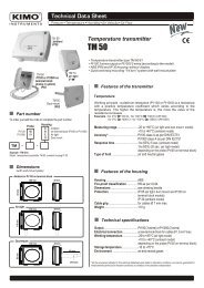
Connection<br />
For models<br />
<strong>TST</strong>-M and <strong>TST</strong>-E<br />
f<br />
Set point<br />
configuration button<br />
d<br />
DIP switch<br />
a<br />
Relay<br />
NC..................Normally closed<br />
COM ..............Common<br />
NO .................Normally open<br />
e<br />
Connection to PC via<br />
LCC 100 software<br />
b<br />
Power supply<br />
Vdc .........direct voltage<br />
GND .......ground<br />
or<br />
c<br />
Cable grip<br />
b<br />
a<br />
Relay<br />
terminal<br />
block<br />
Power supply<br />
terminal block<br />
b<br />
Vac .........alternative voltage (phase)<br />
Vac .........alternative voltage (neutral)<br />
For model<br />
<strong>TST</strong>-B<br />
Pt100<br />
d<br />
terminal<br />
block<br />
2’ 2 1<br />
c<br />
Cable grip : to insert the cable, it is required to slightly cut the rubber.<br />
!<br />
Electrical connections - as per norm NFC15-100<br />
This connection must be made by a qualified technician. To make the connection, the transmitter must not be energized.<br />
For models<br />
<strong>TST</strong>-M and <strong>TST</strong>-E<br />
Relay terminal block COM<br />
Power supply terminal block<br />
NC<br />
NO<br />
Vdc<br />
GND<br />
+<br />
-<br />
-<br />
+<br />
Power supply<br />
24 Vdc<br />
or<br />
or<br />
Vac<br />
Vac<br />
Vac<br />
Vac<br />
~<br />
~ ~ ~<br />
Power supply<br />
24 Vac<br />
Class II<br />
Neutral Phase<br />
Power supply<br />
24 Vac<br />
Connection of the Pt100 probe<br />
For model<br />
<strong>TST</strong>-B<br />
2'<br />
2<br />
1<br />
Pt100<br />
Configuration<br />
Configuration of measuring units, set points, can be carried out different ways : DIP switch, push-button and/or software<br />
(connections e , f and d on drawing “connection”).<br />
Configuration of measuring units by DIP switch<br />
To configure the transmitter, please unscrew the 2 screws from the housing,<br />
and then open it.<br />
d<br />
Electronic<br />
board<br />
DIP switch<br />
Identification of the DIP switches<br />
on the electronic board<br />
1<br />
2<br />
} 3<br />
1 2 3 4<br />
4 DIP<br />
switch 2<br />
DIP<br />
switch 1 Setting of units<br />
Interrupteur<br />
Inactive<br />
To configure the transmitter, it must not be<br />
energized. Then, you can make the settings<br />
required, thanks to the DIP switches (as shown<br />
on the drawing beside). When the transmitter is<br />
configured, you can power it up.<br />
! Caution !<br />
Please follow carefully the combinations beside with the<br />
DIP switch.<br />
If the combination is wrongly done, the following message will<br />
appear on the display of the transmitter “CONF ERROR”.<br />
In that case, you will have to unplug the transmitter, replace the<br />
DIP switches correctly, and then power the transmitter up.<br />
2