KIMO CP300 Data Sheet - Envirolab
KIMO CP300 Data Sheet - Envirolab
KIMO CP300 Data Sheet - Envirolab

You also want an ePaper? Increase the reach of your titles
YUMPU automatically turns print PDFs into web optimized ePapers that Google loves.
Technical <strong>Data</strong> <strong>Sheet</strong><br />
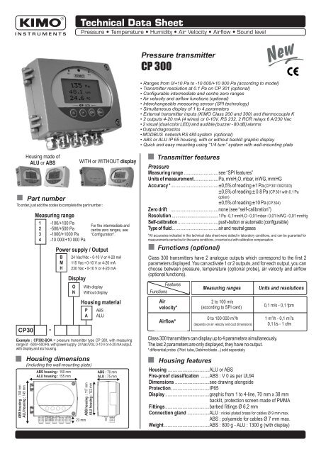
Pressure transmitter<br />
CP 300<br />
New<br />
New<br />
• Ranges from 0/+10 Pa to -10 000/+10 000 Pa (according to model)<br />
• Transmitter resolution at 0.1 Pa on CP 301 (optional)<br />
• Configurable intermediate and centre zero ranges<br />
• Air velocity and airflow functions (optional)<br />
• Interchangeable measuring sensor (SPI technology)<br />
• Simultaneous display of 1 to 4 parameters<br />
• External transmitter inputs (<strong>KIMO</strong> Class 200 and 300) and thermocouple K<br />
• 2 outputs 4-20 mA (4 wires) or 0-10V, RS 232, 2 RCR relays 6 A/230 Vac<br />
• 2 visual (dual color LED) and audible (buzzer - 80 dB) alarms<br />
• Output diagnostics<br />
• MODBUS network RS 485 system (optional)<br />
• ABS or ALU IP 65 housing, with or without backlit graphic display<br />
• Quick and easy mounting using “1/4 turn” system with wall-mounting plate<br />
Housing made of<br />
ALU or ABS<br />
Part number<br />
To order, just add the codes to complete the part number :<br />
CP30<br />
Measuring range<br />
1 -100/+100 Pa<br />
2 -500/+500 Pa<br />
3 -1000/+1000 Pa<br />
4 -10 000/+10 000 Pa<br />
-<br />
WITH or WITHOUT display<br />
Power supply / Output<br />
B<br />
M<br />
H<br />
Display<br />
O<br />
N<br />
For the intermediate and<br />
centre zero ranges, see<br />
“Configuration”.<br />
24 Vac/Vdc • 0-10 V or 4-20 mA<br />
115 Vac • 0-10 V or 4-20 mA<br />
230 Vac • 0-10 V or 4-20 mA<br />
With display<br />
Without display<br />
Housing material<br />
Example : CP302-BOA = pressure transmitter type CP 300, with measuring<br />
range of -500/+500 Pa, with power supply 24 Vac/Vdc, 0-10 V or 4-20 mA output,<br />
with display and alu housing.<br />
ABS housing : 140 mm<br />
ALU housing : 145 mm<br />
P<br />
A<br />
Housing dimensions<br />
(including the wall-mounting plate)<br />
ABS housing : 150 mm<br />
ALU housing : 155 mm<br />
100 mm<br />
23 mm<br />
ABS housing : 117 mm<br />
ALU housing : 122 mm<br />
ABS<br />
ALU<br />
ABS : 70 mm<br />
ALU : 75 mm<br />
Transmitter features<br />
Pressure<br />
Measuring range ............................see “SPI features”<br />
Units of measurement....................Pa, mmH2O, mbar, inWG, mmHG<br />
Accuracy *.......................................±0,5% of reading ±1 Pa (CP 301/302/303)<br />
±0,5% of reading ± 0.8 Pa (CP 301 with 0.1 Pa<br />
option)<br />
......................................................... ±0,5% of reading ±10 Pa (CP 304)<br />
Zero drift .......................................none (see “self-calibration”)<br />
Resolution ..........................................1 Pa - 0,1 mmH2O - 0,01 mbar - 0,01 InWG - 0,01 mmHg<br />
Self-calibration .................................push-button or automatic (configurable)<br />
Type of fluid......................................air and neutral gases<br />
*All accuracies indicated in this technical data sheet were stated in laboratory conditions, and can be guaranted for<br />
measurements carried out in the same conditions, or carried out with calibration compensation.<br />
Functions (optional)<br />
Class 300 transmitters have 2 analogue outputs which correspond to the first 2<br />
parameters displayed. You can activate 1 or 2 outputs, and for each output, you can<br />
choose between pressure, temperature (optional probe), air velocity and airflow<br />
(optional functions).<br />
Functions<br />
Features<br />
Air<br />
velocity*<br />
Airflow*<br />
Housing features<br />
Measuring ranges<br />
2 to 100 m/s<br />
(according to SPI card)<br />
0,1 m/s - 0,1 fpm<br />
3 3 3<br />
0 to 100 000 m /h 1 m /h - 0,1 m /s<br />
(depends on air velocity and duct dimensions)<br />
Class 300 transmitters can display up to 4 parameters simultaneously.<br />
The last 2 parameters are only displayed, they have no output.<br />
* differential probe (Pitot tube, Debimo blade...) sold separately<br />
Units and resolutions<br />
0,1 l/s - 1 cfm<br />
Housing ..................................ALU or ABS<br />
Fire-proof classification .......ABS : V 0 as per UL94<br />
Dimensions ............................see drawing alongside<br />
Protection ...............................IP65<br />
Display ....................................graphic from 1 to 4-line, 70 mm x 38 mm<br />
..................................................... backlit, protection screen made of PMMA<br />
Fittings....................................barbed fittings Ø 6,2 mm<br />
Connection gland ..................ALU : nickel plated brass for cables Ø 9 mm max.<br />
................................................. ABS : polyamide for cables Ø 7 mm max.<br />
Weight.....................................ABS : 800 g - ALU : 1300 g (with display)
SPI system features<br />
Interchangeable Pressure Sensor<br />
The SPI board (Interchangeable Pressure Probe) includes a<br />
piezoresistive sensitive element with its digital electronic system. This<br />
system is individually adjusted and records all the calibration<br />
parameters.<br />
Via the automatic recognition by the transmitter, this digital board is<br />
totally interchangeable. Maintenance, service and calibration are<br />
easily performed on site, with no need to stop the process.<br />
Configurable intermediate and centre zero ranges<br />
Ref. of the probe Pressure range Air velocity* range<br />
SPI 100 -100/+100Pa 2 to 10 m/s<br />
SPI 500 -500/+500 Pa 2 to 22 m/s<br />
SPI 1000 -1000/+1000 Pa 2 to 30 m/s<br />
SPI 10000 -10 000/+10 000 Pa 2 to 100 m/s<br />
* Air velocity ranges are given as an indication based on a differential probe DEBIMO<br />
(Cm = 1). They do not take into account temperature compensation.<br />
The minimum configurable range is 10% of the full range.<br />
Overpressure tolerated..........25 000 Pa (CP 301, CP 302, CP 303)<br />
................................................ 70 000 Pa (CP 304)<br />
Response time .......................1/e (63%) 0,3 sec.<br />
Type ........................................digital<br />
Dimensions ............................L = 60 mm, l = 25 mm<br />
Working temperature ............0 to +50 °C<br />
Storage temperature .............-10 to +70 °C<br />
Air velocity and airflow functions<br />
(optional)<br />
Pressure transmitters working with a differential probe (such as DEBIMO, Pitot<br />
tube, orifice plate...) can be configured with a square root function. Via this<br />
function, and from the differential pressure, the transmitter can calculate air<br />
velocity and/or airflow in a duct.<br />
Debimo blades<br />
Pitot tubes (with or<br />
without temperature<br />
compensation)<br />
Measurement and temperature compensation<br />
Temperature compensation can be made either manually (by entering a temperature<br />
value) or automatically via a thermocouple K temperature probe (optional). This<br />
probe can measure and display temperature, and can compensate air velocity<br />
formula in real-time (for better accuracy).<br />
Type of transmitter........................Thermocouple K (optional)<br />
Measuring range ..........................-200 to +1300 °C (probe dependent)<br />
Units of measurement .................°C, °F<br />
Resolution.....................................0,1°C - 0,1°F<br />
Technical Specifications<br />
Power supply .............................24 Vac / Vdc ±10%<br />
..................................................... 115 Vac or 230 Vac ±10%, 50-60 Hz<br />
Output.........................................2 x 4-20 mA or 2 x 0-10 V (4 wires)<br />
..................................................... maximum load : 500 Ohms (4-20 mA)<br />
..................................................... minimum load : 1 K Ohms (0-10 V)<br />
Galvanic isolation......................inputs and outputs (on 115 Vac/230 Vac models)<br />
outputs (on 24 Vac/Vdc models)<br />
Consumption..............................5 VA<br />
Relays .........................................2 RCR relays 6A / 230 Vac<br />
Visual alarms..............................2 dual color LED<br />
Audible alarm.............................buzzer<br />
Electro-magnetical compatibility ...EN 61 326<br />
Electrical connection ..................screw terminal block for cables Ø 1.5 mm² max<br />
RS 485 communication .............digital : Modbus RTU system<br />
..................................................... communication speed configurable from<br />
2400 to 115200 Bauds<br />
RS 232 communication .............digital : ASCII, proprietary protocol<br />
Working temperature.................0 to +50°C<br />
Storage temperature..................-10 to +70°C<br />
Environment...............................air and neutral gases<br />
Relays and Alarms<br />
Class 300 transmitters has 4 stand-alone and configurable alarms :<br />
2 visual alarms (dual color LED) and 2 relays (contacts).<br />
You can set :<br />
- the parameter (pressure, air velocity, temperature…)<br />
- 1 or 2 set points (rising and falling action) for each alarm<br />
- the time-delay / 60 sec max.<br />
- the alarm action (rising or falling)<br />
- the relay operation mode : positive or negative security<br />
- the audible alarm (buzzer) activation.<br />
Self calibration<br />
Air velocity calculation function :<br />
Air velocity (m/s) = C x C x C x pressure Pa)<br />
M C T<br />
C<br />
M<br />
: cœfficient of the differential probe<br />
C C : coefficient to adapt the measuring system to the specifications of<br />
your air movement conditions .<br />
C T : temperature compensation coefficient, with the formula below :<br />
C =<br />
T<br />
574,2 x temp. (°C) + 156842,77<br />
101325<br />
Airflow calculation function :<br />
3 2<br />
Airflow (m /h) = air velocity (m/s) x surface (m ) x 3600<br />
Surface : setting of duct type (rectangular or circular) and duct<br />
dimensions (in mm or in inches).<br />
Thanks to the temperature compensation of the gain (from 0 to 50°C) and to the self<br />
calibration system, Class 300 transmitters guarantee an excellent long-term<br />
stability, along with a great measurement accuracy.<br />
Self calibration principle : the microprocessor drives an electro-valve that<br />
compensates for any long-term drift of the sensitive element.<br />
Compensation is made by regular automatic adjustment of the zero. True differential<br />
pressure measurement is then made regardless of the environmental conditions of<br />
the transmitter.<br />
Electro-valve lifetime .....................100-million cycles<br />
Benefit..............................................no zero drift<br />
Self calibration frequency .............can be disabled or set between 1 and 60 min<br />
Integration of pressure measurement<br />
The pressure measurement element is very sensitive and reacts to pressure<br />
changes. When making measurements in unstable air movement conditions, the<br />
pressure measurement may fluctuate. The integration coefficient (from 0 to 9)<br />
makes an average of the measurements ; this helps to avoid any excessive<br />
variations and guarantees a stable measurement.
{<br />
{<br />
Connection<br />
Output selection<br />
4-20 mA<br />
or 0-10 V h<br />
Manual k<br />
self calibration<br />
SPI sensitive<br />
element j<br />
d<br />
Analogue<br />
outputs<br />
c<br />
RS 485<br />
connection<br />
b Relay<br />
terminal blocks<br />
a<br />
Power supply<br />
terminal block<br />
e<br />
RS 232 connector<br />
Pressure f<br />
connections<br />
d<br />
Thermocouple K<br />
input<br />
RS485<br />
Analogue output 1 Analogue output 2 (Modbus) Relay 1 Relay 2<br />
c<br />
b<br />
g Connection fittings<br />
a or a<br />
i<br />
The ticked box shows<br />
the power supply type<br />
of the transmitter<br />
(230 Vac shown above).<br />
or<br />
24 Vdc / ac<br />
230 Vac<br />
115 Vac<br />
a<br />
0-10 V ..............voltage<br />
GND.................ground<br />
4-20 mA ...........current<br />
0-10 V ..............voltage<br />
GND.................ground<br />
4-20 mA ...........current<br />
B<br />
-<br />
A<br />
+<br />
NO......normally open<br />
COM...common<br />
NC......normally closed<br />
NO......normally open<br />
COM...common<br />
NC......normally closed<br />
For 24 Vdc<br />
power supply models<br />
_<br />
+<br />
For 24 Vac<br />
power supply models<br />
~ ~<br />
For 230 Vac 115 Vac<br />
power supply models<br />
security earth<br />
neutral<br />
phase<br />
!<br />
Electrical connections - as per NFC15-100 Norm<br />
This connection must be made by a qualified technician. Whilst making the connection, the transmitter must not be energized.<br />
Power supply connection :<br />
!<br />
Before making the connection, you must first check the<br />
power supply which is indicated on the transmitter board<br />
(see i on the connection drawing).<br />
• For 24 Vdc power supply models :<br />
Power supply<br />
terminal block<br />
24 Vdc<br />
power supply<br />
• For 115 or 230 Vac power supply models :<br />
ground Phase<br />
Neutral<br />
-<br />
+<br />
• For 24 Vac power supply models :<br />
Power supply<br />
terminal block<br />
230 Vac<br />
Pe<br />
N<br />
L<br />
power supply<br />
Class II<br />
~<br />
Vac Vac<br />
~ ~<br />
24 Vac<br />
~<br />
Power supply<br />
terminal block<br />
-<br />
OR<br />
230 Vac<br />
+<br />
Pe<br />
N<br />
L<br />
N<br />
Ph<br />
power supply<br />
N<br />
24 Vac<br />
L<br />
Output signal selection<br />
voltage (0-10 V) or current (4-20 mA)<br />
The on-off switch located on the left top of the<br />
transmitter (see h on connection drawing) allows<br />
selection of the required outputs.<br />
Down<br />
0-10 V<br />
Output connection :<br />
• 4-20mA current output :<br />
Output<br />
terminal block<br />
Regulator display -<br />
or PLC/BMS<br />
passive type<br />
+<br />
• 0-10 V voltage output :<br />
Output<br />
terminal block<br />
0-10 V<br />
0-10 V<br />
Up<br />
4-20 mA<br />
+<br />
GND<br />
-<br />
GND<br />
-<br />
4-20 mA<br />
+<br />
4-20 mA<br />
Connection of SUB-D15<br />
RS 232 and RS 485 (Modbus)<br />
( see e on drawing connection)<br />
8<br />
7<br />
6<br />
5<br />
4<br />
3<br />
15 14 13 12 11 10<br />
Pin # Description<br />
1 NC *<br />
2 NC *<br />
3 NC *<br />
4 B - (RS 485)<br />
5 A + (RS 485)<br />
6 NC *<br />
7 NC *<br />
8 NC *<br />
9 RX (RS 232)<br />
10 NC *<br />
11 TX (RS 232)<br />
12 NC *<br />
13 NC *<br />
14 NC *<br />
15 GND (RS 232)<br />
! CAUTION ! :<br />
NC * = DO NOT CONNECT<br />
2<br />
9<br />
1<br />
115 / 230 Vac<br />
power supply<br />
Regulator display<br />
or PLC/BMS<br />
passive type<br />
+<br />
-
Numerical communication<br />
RS 232 communication<br />
• Via the RS 232 connection, the CP 300 can display 1 or 2 parameters that<br />
are measured by other Class 200 and 300 transmitters.<br />
Benefit : the CP 300 can display (in addition to the<br />
pressure), other parameters such as temperature and<br />
humidity from a TH 200 (for example).<br />
• Via the RS 232 connection, you can also configure<br />
your transmitter with the LCC-300 software.<br />
• The RS 232 connection cable is available in 2m, 5m<br />
or 10m (maximum) lengths.<br />
Modbus network (RS 485 system)<br />
• Class 300 transmitters can be linked<br />
in one network, on a RS 485 home<br />
bus. They can also<br />
be integrated into<br />
an existing<br />
network.<br />
• When a Class 200 or 300 transmitter<br />
is connected to a CP 300 (with RS 232<br />
connection), all the measurements can be given to the PLC/BMS via the<br />
RS 485, with only one address for the 2 transmitters.<br />
• The RS 485 digital communication is a 2-wire network, on which the<br />
transmitters are connected in parallel. They are connected to a PLC/BMS via the<br />
RTU Modbus communication system. Since the CP 300 can be configured with<br />
the keypad, the MODBUS enables remote configuration, to measure 1 or 2<br />
parameters or to see the status of the alarms...<br />
Configuration<br />
RS 485<br />
RS 232<br />
0V<br />
4 mA<br />
RS 232<br />
You can configure all the parameters of the transmitter : units, measuring<br />
ranges, alarms, outputs, channels, calculation formula.... via the different<br />
methods shown below.<br />
Via keypad : only on models with display<br />
A code-locking system for keypad guarantees the security of the<br />
installation. See configuration manual.<br />
Via remote control (optional) only on models with display.<br />
This is convenient to configure the transmitters located in hard to reach<br />
positions. Same method as with a keypad.<br />
Via software (optional) : on all models.<br />
Simple and user-friendly configuration. See LCC-300 user manual.<br />
Via MODBUS (optional) : on all models.<br />
Configuration of all parameters from your PC, via the supervision or data<br />
acquisition software.<br />
Configurable analogue outputs<br />
Configure the range according to your needs : outputs are automatically adjusted<br />
to the new measuring ranges.<br />
Range<br />
+100<br />
-100<br />
0<br />
(Pa, mmH2O...)<br />
Range with centre zero (-50/0/+50 Pa),<br />
with offset zero (-30/0/+70Pa) or<br />
standard range (0 /+100 Pa) => you can 0V<br />
10V<br />
4 mA<br />
20 mA<br />
configure your own intermediate ranges<br />
according to your needs, between 10%<br />
New range<br />
+100<br />
and 100% of the full scale. The minimum -100 0 50<br />
(Pa, mmH2O...)<br />
configurable range is 10% of the full<br />
scale.<br />
10V<br />
20 mA<br />
www.kimo.fr Distributed by :<br />
EXPORT DEPARTMENT<br />
Tel : + 33. 1. 60. 06. 69. 25 - Fax : + 33. 1. 60. 06. 69. 29<br />
e-mail : export@kimo.fr<br />
Calibration<br />
Adjusting and calibration on site<br />
:<br />
The professional configuration interface,<br />
with a dynamic pressure calibration<br />
bench, enables you to adjust and<br />
calibrate your transmitters directly on site<br />
or in laboratories.<br />
Output diagnostics :<br />
With this function, you can check with a<br />
multimeter (or on a regulator/display, or on<br />
a PLC/BMS) if the transmitter outputs work<br />
properly. The transmitter generates a<br />
voltage of 0 V, 5 V and 10 V or a current of<br />
4 mA, 12 mA and 20 mA .<br />
Certificate :<br />
• Class 300 transmitters are supplied with adjusting c e r t i f i c a t e s .<br />
Calibration certificates are offered as an option.<br />
• The SPI sensitive elements (interchangeable pressure probes)<br />
are supplied with adjusting certificates.<br />
Mounting<br />
To install the transmitter on a wall : fix the stainless steel plate to the<br />
wall (this plate is supplied with the transmitter). Drilling : 8 mm (with<br />
the screws and wall-plugs supplied with<br />
the transmitter). Insert the transmitter on<br />
the plate (see A on the drawing shown<br />
beside) by aligning it at 30°. Rotate its<br />
housing in clockwise direction until you<br />
hear a “click” which confirms that the<br />
transmitter is correctly installed. Then,<br />
open the housing, lock the clamping<br />
system of the housing on the plate, with the screw as shown. (to<br />
remove the transmitter from the plate, remember to remove the<br />
screw first).<br />
120 mm<br />
Stainless<br />
steel<br />
plate<br />
! CAUTION !<br />
Maintenance<br />
Avoid aggressive solvents.<br />
Protect the transmitter and probes from any cleaning product<br />
containing formol, which may be used for cleaning rooms or<br />
ducts.<br />
Options<br />
SQR/2 (square root extraction) function for<br />
the calculation of air velocity and airflow<br />
Digital output for Modbus network (RS 485 system)<br />
LCC-300 configuration software with RS 232 cable<br />
Infrared remote control for configuration (only for models<br />
with display)<br />
Calibration certificate.<br />
Transmitter resolution at 0.1 Pa (CP 301)<br />
Optional accessories<br />
Pitot tubes<br />
Debimo measuring blades<br />
Thermocouple K probes<br />
Mounting brackets<br />
A<br />
65 mm<br />
A<br />
65 mm<br />
98 mm<br />
Ø 5,4 mm<br />
When the transmitter is installed and powered on, it will<br />
automatically perform an autozero procedure. This guarantees<br />
that the transmitter works properly, whatever its position.<br />
Sliding fittings<br />
Connection gland<br />
Clear tube<br />
Through-connections<br />
Pressure connections<br />
Ref. FT ang - CP 300 - 05/09 D - RCS (24) Périgueux B349 282 095 Non-contractual document - We reserve the right to modify the characteristics of our products without prior notice.