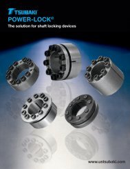
Tsubaki Complete Energy Series
Tsubaki Complete Energy Series
Tsubaki Complete Energy Series
You also want an ePaper? Increase the reach of your titles
YUMPU automatically turns print PDFs into web optimized ePapers that Google loves.
Locking Bolts Taper Ring (A) Outer Ring Inner Ring Taper Ring (B)<br />
Model Number<br />
Inch <strong>Series</strong>: PL 2 AS<br />
AS <strong>Series</strong><br />
Shaft Dia. (inch)<br />
POWER-LOCK ®<br />
AS Inch <strong>Series</strong><br />
Features & Applications<br />
• Multipurpose<br />
Ideally structured and highly reliable locking device<br />
• Low Machining Costs<br />
Keyway, splines, presses and thermal fittings are not<br />
required. Optimum performance is achieved with low shaft<br />
and hub tolerances minimizing the total machining costs.<br />
• Easy to Install<br />
Installs or removes just by tightening or loosening of bolts.<br />
No need to hassle with adjusting keyways and thermal<br />
fittings.<br />
• Options to Fit Every Application<br />
Stainless Steel and electroless nickel plating options are<br />
offered for standard models. Both are highly durable in<br />
corrosive or clean room environments.<br />
Power-Lock ®<br />
AS AS Selection Selection<br />
AS Inch/Metric AS Inch/Metric Guide Guide<br />
<strong>Series</strong><br />
<strong>Series</strong><br />
AS Selection Guide<br />
Selection Guide:<br />
Selection Guide:<br />
Power-Lock<br />
Power-Lock<br />
www.tsubaki.ca<br />
1. a) Determine the required maximum torque (MtC) to be transmitted:<br />
1. a) Torque Determine MtC = the 5252 required x HP maximum (ft-lb) torque (MtC) to be transmitted:<br />
1. a) Determine the required maximum torque (MtC) to be transmitted:<br />
RPM<br />
Torque MtC = 5252 x HP<br />
(ft-lb)<br />
b) If combined torsional and axial loads are to be transmitted,<br />
RPM<br />
calculate If the resulting torque as follows:<br />
b) If combined torsional and axial loads are to to be be transmitted,<br />
calculate the resulting torque as follows:<br />
M t res =<br />
MtC +( 2 res Fxd ) 2 < M t<br />
M t res =<br />
MtC +( 2 Fxd 24<br />
2 < M t<br />
24<br />
Where:<br />
Mt res = resultant torque to be transmitted<br />
Where:<br />
MtC = actual or maximum torque to be transmitted (ft-lb). This value is calculated in step 1 a) above.<br />
Mt res = resultant torque to be transmitted<br />
F = axial load/thrust to be transmitted to (lbs)<br />
MtC = actual or maximum torque to be be transmitted (ft-lb). This This value value is calculated is in step in step 1 a) 1 above. a) above.<br />
d = shaft diameter (inches)<br />
F axial load/thrust to be transmitted (lbs) (lbs)<br />
Mt = maximum transmissible torque (ft-lb) of the Power Lock as specified in the AS Power-Lock specification tables.<br />
d = shaft diameter (inches)<br />
Mt = maximum transmissible torque (ft-lb) of the Power-Lock ® as as specified in in the the AS AS Power-Lock specification ® specification tables.<br />
2. Select aPower-Lock for the shaft diameter (d) from the AS Power-Lock specification tables in this catalogue and tables. verify that the<br />
2. Select corresponding a maximum ® transmissible torque (Mt) meets the AS torque requirement ® that was calculated tables in this in step catalogue 1a) above. and If torque is<br />
2. Select aPower-Lock for the shaft diameter (d) from the AS Power-Lock specification tables in this catalogue and verify that the<br />
verify the primary that the requirement, corresponding select maximum the necessary transmissible torque (Mt) torque from (Mt) the same meets specification the torque requirement tables and determine that was the calculated corresponding If shaft<br />
corresponding maximum transmissible torque (Mt) meets the torque requirement that was calculated in step 1a) above. If torque is<br />
in diameter step 1 a) (d).<br />
the primary above. requirement, If torque select is theprimary necessary requirement, torque (Mt) select from the the same necessary specification torque (Mt) tables from andthe determine same specification<br />
the corresponding shaft<br />
tables Note: Required and determine peak torque the corresponding should never shaft exceed diameter specified (d). transmissible torque (Mt).<br />
diameter (d).<br />
Note: Required peak torque should never exceed specified transmissible torque torque (Mt). (Mt).<br />
To increase transmissible torque (Mt):<br />
Install 2 or 3 Power-Locks in series, (Mt): increasing transmissible torque as follows:<br />
To increase transmissible torque (Mt):<br />
- with 2Power-Locks: Mtrans.= ® in series, 2 x Mt<br />
torque as follows:<br />
Install 2 or 3 Power-Locks in series, increasing transmissible torque as follows:<br />
- with 3Power-Locks: ® Mtrans.= : 3 2 x x Mt<br />
with 2Power-Locks: Mtrans.= 2 Mt<br />
Mt<br />
The hub 3 must be long ® enough : to accommodate 3 x Mt the assemblies.<br />
- with 3Power-Locks: Mtrans.= 3 x Mt<br />
The hub must be be long enough to to accommodate the the assemblies. assemblies.<br />
3. Determine the recommended minimum hub outside diameter (DN) for the Power-Lock selected from the specification tables (which<br />
3. Determine the recommended minimum hub outside diameter (DN) for the Power-Lock ® selected from the<br />
show<br />
specification the DN for material<br />
3. Determine the tables with ayield<br />
recommended (which show point<br />
minimum the DN for of 32,000<br />
hubmaterial p.s.i.)<br />
outsidewith For other<br />
diameter a yield (DN) point yield<br />
for point<br />
the of 32,000 materials,<br />
Power-Lock p.s.i.) calculate<br />
selected For other the<br />
from yield hub<br />
thepoint<br />
outside diameter<br />
specification (DN)<br />
tables by<br />
(which<br />
using theDN following equation:<br />
materials, show the DN calculate for material the hub withoutside ayield point diameter of 32,000 (DN) by p.s.i.) using For the other following yield point equation: materials, calculate the hub outside diameter (DN) by<br />
using the following equation:<br />
YP + (K<br />
D N > D x<br />
3 x pH)<br />
(inches or mm)<br />
YP - (K YP + (K 3 x pH)<br />
D N > D x<br />
3 pH)<br />
YP - (K 3 x (inches or mm)<br />
pH)<br />
Where Where<br />
D = of the Power-Lock ® and hub counter bore inside diameter (inches or mm).<br />
D= Outer diameter of the Power-Lock and hub counter bore inside diameter (inches or mm).<br />
Where<br />
or YP = yield point of hub material (p.s.i. or MPa)<br />
D= Outer diameter of the Power-Lock and hub counter ® and bore hub inside bore. See diameter specification (inches or tables mm). (p.s.i. or MPa).<br />
pH<br />
YP = Contact pressure between the Power-Lock and hub bore. See specification tables (p.s.i. or MPa).<br />
yield point of hub material ® )<br />
(p.s.i. or MPa)<br />
K3 = 0.6 (one Power-Lock)<br />
pH Contact pressure between 3 ® the Power-Lock and hub bore. See specification tables (p.s.i. or MPa).<br />
in K3<br />
K3<br />
K3 = 0.8<br />
0.6 (2 or<br />
(one 3Power-Locks in series)<br />
Power-Lock)<br />
K3 See Hub layout diagram on next page for more detail on on value of of K3 K3<br />
K3 = 0.8 (2 or 3Power-Locks in series)<br />
Note: SeeUse Hubeither layoutall diagram imperial onvalues next page (inches/p.s.i.) for more detail or all metric on value values of<br />
K3<br />
K3(mm/MPa) when calculating the value of DN.<br />
Note: Use either all imperial values (inches/p.s.i.) or all metric values (mm/MPa) when calculating the value of DN.<br />
Note: Use either all imperial values (inches/p.s.i.) or all metric values (mm/MPa) when calculating the value of<br />
DN.<br />
DN.<br />
32<br />
33


