Tsubaki Complete Energy Series
Tsubaki Complete Energy Series
Tsubaki Complete Energy Series

Create successful ePaper yourself
Turn your PDF publications into a flip-book with our unique Google optimized e-Paper software.
For when it really matters<br />
For when it really matters<br />
<strong>Tsubaki</strong> of Canada Limited<br />
1630 Drew Road, Mississauga, Ontario, CANADA L5S 1J6<br />
Tel: 905-676-0400 Fax: 905-676-0904 Toll-Free: 800-263-7088<br />
www.tsubaki.ca e-mail: info@tsubaki.ca<br />
Edmonton Office & Warehouse<br />
10035-56th Avenue, Edmonton, AB, CANADA T6E 5L7<br />
Tel: 780-438-6073 Fax: 780-436-4929 Toll-Free: 800-661-8811<br />
www.tsubaki.ca e-mail: info@tsubaki.ca<br />
Power and<br />
performance<br />
for oil<br />
industry<br />
operations<br />
CAT-ENERGY-TCL<br />
Note: In accordance with the policy of <strong>Tsubaki</strong> of Canada Limited to consistently<br />
improve its products, the specifications in this catalogue are subject to change<br />
without notice. Please contact <strong>Tsubaki</strong> for current prices.<br />
Copyright © 2013 <strong>Tsubaki</strong> of Canada Limited. Errors and Omissions Excepted.<br />
Disclaimer: <strong>Tsubaki</strong> of Canada Limited makes every effort to ensure that the<br />
information in this catalogue is current and accurate, but cannot accept responsibility<br />
or liability for any loss or damage suffered as a result of information contained herein.<br />
Chains Sprockets Cable Carriers<br />
2 0 1 3 e n e r g y s e r i e s C a t a l o g u e
Table of Contents<br />
www.tsubaki.ca<br />
TSUBAKI only offers the best…<br />
ENERGY SERIES CHAIN<br />
+<br />
ENERGY SERIES SPROCKETS<br />
+<br />
Power-Lock ®<br />
+<br />
Cables<br />
+<br />
Cable Carrier<br />
+<br />
Industry Knowledge<br />
+<br />
<strong>Tsubaki</strong> Advantage<br />
=<br />
TOTAL ENERGY SERIES SOLUTION<br />
dvantage<br />
by <strong>Tsubaki</strong><br />
TSUBAKI ENERGY SERIES<br />
TSUBAKI Environmental Action Plan 4-5<br />
TSUBAKI Global Network 6-7<br />
<strong>Energy</strong> <strong>Series</strong> Chain 8-11<br />
Introduction - When Power Counts 8-9<br />
Single and Multi Strand Chain Dimensions 10-11<br />
<strong>Energy</strong> <strong>Series</strong> Sprockets 12-29<br />
Specifications, Features, Options and Design 12-13<br />
80 Single and Multi Strand 14-15<br />
100 Single and Multi Strand 16-17<br />
120 Single and Multi Strand 18-19<br />
140 Single and Multi Strand 20-21<br />
160 Single and Multi Strand 22-23<br />
180 Single and Multi Strand 24-25<br />
200 Single and Multi Strand 26-27<br />
240 Single and Multi Strand 28-29<br />
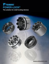
Power-Lock ® 30-41<br />
Features & Applications 30-31<br />
AS <strong>Series</strong> - Features & Applications 32<br />
AS <strong>Series</strong> - Selection Guide 33-34<br />
AS <strong>Series</strong> - Installation Guide 35-36<br />
AS <strong>Series</strong> - Specifications 37<br />
AD <strong>Series</strong> - Features & Applications 38<br />
AD <strong>Series</strong> - Selection Guide 39<br />
AD <strong>Series</strong> - Installation Guide 40<br />
AD <strong>Series</strong> - Specifications 41<br />
KabelSchlepp 42-51<br />
M <strong>Series</strong> 43<br />
S/SX <strong>Series</strong> 44<br />
UNIFLEX 45<br />
Cable Carrier - Overview of inside width 46-47<br />
Cables for Cable Carriers 48-49<br />
Cable Carrier Applications in Practice 50-51<br />
<strong>Energy</strong> Critical Applications 52-56<br />
Coil Tube Injector 52<br />
Coil Tube Unit 53<br />
Pipe Spinner/Handler 54<br />
Catwalk 55<br />
Drawworks 56<br />
Technical Services 57<br />
2 3
TSUBAKI<br />
Environmental<br />
Action Plan<br />
With its focus on manufacturing,TSUBAKI<br />
takes a unique approach to the challenges<br />
of environmental conservation.<br />
Principle<br />
The TSUBAKI Group believes that environmental conservation is a<br />
critical challenge facing humanity. We will remain mindful of the<br />
environment in all our operations and contribute to the world through<br />
our workmanship.<br />
Environmental Policy<br />
• We will acknowledge the environmental impact of our operations,<br />
products, and services. In the interests of environmental<br />
conservation, we will use our creativity to exhibit industry<br />
leadership in reducing our environmental load.<br />
• We will create a management system for environmental conservation<br />
and will promote pollution control and continual improvement.<br />
• We will strictly comply with environmental laws, rules, and regulations<br />
and will seek to develop good relationships with our stakeholders.<br />
• Through environmental training and in-house public relations, we<br />
will work to enhance awareness of environmental conservation<br />
among all TSUBAKI Group employees.<br />
When an environment in harmony with people and our planet really matters<br />
We are applying the collective expertise of the<br />
TSUBAKI Group to an Environmental Action Plan<br />
that takes a global perspective.<br />
Accredited with ISO 14001 Certification for Our Environmental Management System<br />
• All TSUBAKI Group workplaces in Japan have acquired ISO 14001 certification; a growing number<br />
of TSUBAKI Group workplaces outside Japan are doing so as well.<br />
Ongoing Efforts to Reduce Our Environmental Impact<br />
• We are reducing CO2 emissions resulting from our energy consumption.<br />
• We are implementing recycling and waste-reduction initiatives.<br />
Ensuring Strict Compliance with Environmental Laws and Regulations<br />
• We are instituting a management system at all our workplaces to ensure full compliance<br />
with local laws and regulations.<br />
Initiatives Targeting Eco-Friendly Products<br />
• Our adoption of green procurement encompasses outsourcing of processing,<br />
production materials, and consumables.<br />
• We incorporate environmentally friendly design into the product development stage.<br />
• We are eliminating hazardous chemicals from our products.<br />
Environmental Training, Public Relations and Other Initiatives<br />
• We are enhancing our environmental website and are providing timely information about<br />
our operations.<br />
Reducing CO2 emissions with<br />
a highly efficient cogeneration system.<br />
This heat exchange system cools our<br />
injection molding equipment with heat<br />
from an electrical generator.<br />
Plastic Chain<br />
Linisort-V<br />
NEP Chain<br />
Did you know that many of TSUBAKI’s eco-friendly<br />
products are part of our daily lives?<br />
Eco-Friendly Products<br />
Reduce, Reuse and Recycle are the “three R’s” of environmental<br />
conservation. We develop products and technologies that<br />
contribute widely to environmental conservation.<br />
Recyclable Plastic Chain<br />
By collecting and recycling used plastic chains, we are promoting<br />
resource conservation and the adoption of recycling.<br />
Linisort Sorting Systems<br />
Linisort systems incorporate linear motors that provide silent,<br />
eco-friendly sorting. In addition to featuring a compact<br />
configuration, low weight, and low energy consumption, these<br />
systems are designed for environmentally friendly disassembly,<br />
part sorting, collecting and recycling.<br />
Eco Chain <strong>Series</strong><br />
NEP chain is highly corrosion-resistant chain with a surface<br />
coating free from designated hazardous chemicals (RoHS Directive<br />
compliant). This product series also includes our Lambda Roller<br />
Chain, which offers superior oil-free and long-life characteristics;<br />
plastic roller chain, which features low-noise operation achieved<br />
with our proprietary engineering plastic technology, and stainless<br />
steel water processing chain, a field-proven product that has<br />
earned an excellent reputation after decades of successful use in<br />
wastewater treatment facilities throughout Japan.<br />
Products for the<br />
Environmental Market<br />
Water Treatment Facilities<br />
and Equipment<br />
Our sewage treatment facilities and<br />
equipment help maintain the water<br />
quality in water treatment facilities<br />
throughout Japan.<br />
Conveyors for the<br />
Environmental Market<br />
Our conveyance devices for<br />
environmental facilities are used<br />
in applications such as waste<br />
incineration and processing of<br />
industrial waste, household refuse,<br />
and sludge. And with equipment<br />
provided by TSUBAKIMOTO<br />
Bulk Systems Corporation and<br />
TSUBAKIMOTO Mayfran Inc., we<br />
provide metal conveyance and<br />
coolant processing equipment for<br />
metal machining and processing<br />
applications. Clearly, our conveyor<br />
products are meeting the needs of<br />
the environmental market.<br />
4<br />
5
<strong>Tsubaki</strong><br />
Global Network<br />
Wherever you are in the world, our<br />
production and sales network is able to<br />
provide your business with the immediate<br />
support it needs.<br />
<strong>Tsubaki</strong> Profile<br />
U.S. <strong>Tsubaki</strong>, Inc. (UST) <strong>Tsubaki</strong> of Canada Limited <strong>Tsubaki</strong>moto Europe B.V. Korea Conveyor Ind. Co., Ltd. <strong>Tsubaki</strong>moto Automotive (Shanghai) Co., Ltd.<br />
UST Portland Plant UST Holyoke Plant UST Sandusky Plant UST Chicopee Plant<br />
<strong>Tsubaki</strong>moto Singapore Pte. Ltd. <strong>Tsubaki</strong>moto Automotive (Thailand) Co., Ltd. Taiwan <strong>Tsubaki</strong>moto Co. <strong>Tsubaki</strong> Australia Pty. Limited<br />
6<br />
7
<strong>Tsubaki</strong> offers a wide range of sizes — from 80 through<br />
240 and up to 10 strands wide — manufactured at our<br />
Holyoke, Mass. facility. With our trained manufacturing<br />
team and extensive inventory in stock, you get prompt<br />
service on your order.<br />
Wider waist stands<br />
up to maximum<br />
shock loads and<br />
extends fatigue life<br />
Ballized holes for<br />
tighter tolerances<br />
and a smoother fit<br />
Shot-peened link plates<br />
add fatigue resistance<br />
<strong>Energy</strong> <strong>Series</strong> Chain - When Power Counts<br />
High productivity, high speeds, high shock loads, and high cyclic loading in the oil field put great demands<br />
on roller chain. Count on the experts at <strong>Tsubaki</strong> to deliver <strong>Energy</strong> <strong>Series</strong> — the chains you need to keep<br />
your operation running smoothly.<br />
Engineered for quality<br />
and performance<br />
<strong>Tsubaki</strong> builds performance into every <strong>Energy</strong><br />
<strong>Series</strong> chain. We start with the highest-quality<br />
steel, manufacture all parts to stringent tolerances,<br />
and provide the most effective heat-treatment<br />
processes to maximize tensile strength and shock<br />
load resistance. That means long-lasting chain in<br />
the toughest applications.<br />
Pre-stressed for performance<br />
out of the box<br />
All chains are pre-stressed to ensure uniform<br />
load distribution and to minimize initial elongation.<br />
The result is better operation immediately following<br />
installation and throughout the life of the chain.<br />
Stronger pins for<br />
longer chain life<br />
Drilling applications put a lot of stress on pins,<br />
and pin wear can cause early chain failure.<br />
<strong>Energy</strong> <strong>Series</strong> pins are made of special materials,<br />
precision-ground to ensure accurate fit, and<br />
assembled only after our proprietary heat treatment.<br />
The result is tough, through-hardened pins that<br />
increase fatigue strength and allow the chain to<br />
better withstand shock loads.<br />
Ballized holes for<br />
smoother contact<br />
Fatigue cracks can start from imperfections in the<br />
plate holes. <strong>Energy</strong> <strong>Series</strong> chains are manufactured<br />
to minimize imperfections. After heat treatment,<br />
the pitch holes on the side plates are ball drifted<br />
to impart residual<br />
compressive<br />
stress and create<br />
extremely smooth<br />
hole surfaces,<br />
which maximizes<br />
fatigue strength.<br />
Z-cotters hold tight, minimizing<br />
vibration and maximizing fatigue<br />
life, yet allow easy assembly and<br />
disassembly in the field.<br />
Pitch-compensated link plates<br />
maintain maximum strength<br />
<strong>Energy</strong> <strong>Series</strong> link plates<br />
have wider waists, putting<br />
more steel where you<br />
need it to handle shock<br />
loads. The added plate<br />
strength creates a rigid<br />
link with less deflection<br />
under load.<br />
Centre plates are pitch-compensated,<br />
creating a contact fit that allows easy<br />
cutting and assembly while maximizing<br />
chain strength. The plates hold tighter<br />
and share the load equally, creating<br />
higher fatigue resistance and longer<br />
lasting chain.<br />
Factory-applied hot-dip lube penetrates deeper<br />
Building better bushings<br />
and rollers that last<br />
Roller and bushing<br />
designs play significant<br />
parts in chain life.<br />
Every <strong>Energy</strong> <strong>Series</strong><br />
chain uses solid rollers,<br />
which are carefully<br />
formed from high-grade steel into optimal<br />
roundness and then heat treated and<br />
shot peened for toughness and strength.<br />
<strong>Energy</strong> <strong>Series</strong> features solid bushings<br />
for large sizes and precision-formed<br />
bushings for small sizes. Both types<br />
of bushings are fabricated to be the<br />
roundest in the industry for smooth,<br />
long-lasting operations.<br />
The final manufacturing step before chains are shipped is one of the most important.<br />
<strong>Tsubaki</strong> dips each chain in hot lubricant, so it penetrates deeper than typical surface sprays.<br />
This special step puts the lube where you need it — deep into the pin and bushing area —<br />
to extend the working life of the chain.<br />
8<br />
proudly made in usa.<br />
9
<strong>Energy</strong> <strong>Series</strong> Chain<br />
www.tsubaki.ca<br />
Z-Cotter Dimensions<br />
80 100 120 140 160 180 200<br />
D 0.09 0.09 0.11 0.146 0.146 0.185 0.185<br />
L 1.50 1.87 2.23 2.600 2.970 3.380 3.750<br />
L<br />
L1<br />
C, D<br />
c, d<br />
T-Cotter Dimensions<br />
264 / 240<br />
C 0.245<br />
D 0.237<br />
c 0.230<br />
<strong>Energy</strong> <strong>Series</strong> Single and Multi Strand Chain Dimensions<br />
D<br />
L<br />
25°<br />
25°<br />
30°<br />
d 0.215<br />
L 0.745<br />
L1 1.435<br />
All units are in inches unless otherwise indicated.<br />
Chain<br />
No.<br />
Strands<br />
1 2 3<br />
Pitch L1 L2 L D R W h H C T ATS 1 WPF 2 L1 L2 ATS 1 WPF 2 L1 L2 ATS 1 WPF 2<br />
Strands<br />
4 5 6 8 10<br />
L1 L2 ATS 1 WPF 2 L1 L2 ATS 1 WPF 2 L1 L2 ATS 1 WPF 2 L1 L2 ATS 1 WPF 2 L1 L2 ATS 1 WPF 2<br />
80 1.00 0.640 0.758 1.398 0.312 0.625 0.625 0.819 0.949 1.153 0.125 17,600 1.79 1.217 1.335 35,200 3.54 1.793 1.911 52,800 5.30<br />
100 1.25 0.778 0.900 1.678 0.375 0.750 0.750 1.025 1.185 1.408 0.156 27,300 2.68 1.482 1.604 54,600 5.27 2.186 2.308 81,900 7.91<br />
120 1.50 0.980 1.138 2.118 0.437 0.875 1.000 1.228 1.425 1.789 0.187 39,700 3.98 1.875 2.033 71,880 7.86 2.769 2.927 107,820 11.78<br />
140 1.75 1.059 1.248 2.307 0.500 1.000 1.000 1.433 1.661 1.924 0.219 52,900 5.03 2.021 2.210 94,370 9.97 2.983 3.172 141,550 14.92<br />
160 2.00 1.254 1.451 2.705 0.562 1.125 1.250 1.638 1.898 2.305 0.250 68,300 6.79 2.407 2.604 136,600 13.47 3.559 3.756 204,900 20.17<br />
180 2.25 1.404 1.671 3.075 0.687 1.406 1.406 1.843 2.134 2.592 0.281 80,500 9.04 2.700 2.967 161,000 17.82 3.996 4.263 241,500 25.68<br />
200 2.50 1.535 1.764 3.299 0.781 1.562 1.500 2.047 2.374 2.817 0.312 105,800 11.08 2.944 3.173 211,600 21.93 4.352 4.581 317,400 32.94<br />
240 3.00 1.886 2.185 4.071 0.937 1.875 1.875 2.457 2.850 3.458 0.375 154,300 16.46 3.615 3.914 308,600 32.32 5.344 5.643 462,900 48.11<br />
80H 1.00 0.720 0.823 1.543 0.312 0.625 0.625 0.819 0.949 1.283 0.156 20,900 2.08 1.362 1.465 41,800 4.15 2.003 2.106 62,700 6.21<br />
100H 1.25 0.858 0.965 1.823 0.375 0.750 0.750 1.025 1.185 1.539 0.187 32,000 3.17 1.628 1.735 64,000 6.07 2.397 2.504 96,000 9.10<br />
120H 1.50 1.061 1.203 2.264 0.437 0.875 1.000 1.228 1.425 1.924 0.219 43,000 4.38 2.023 2.165 71,880 8.67 2.985 3.127 107,820 12.99<br />
140H 1.75 1.138 1.303 2.441 0.500 1.000 1.000 1.433 1.661 2.055 0.250 56,200 5.54 2.166 2.331 94,370 11.01 3.193 3.358 141,550 16.48<br />
160H 2.00 1.337 1.514 2.851 0.562 1.125 1.250 1.638 1.898 2.437 0.281 71,700 7.35 2.556 2.733 143,400 14.64 3.774 3.951 215,100 21.93<br />
180H 2.25 1.486 1.734 3.221 0.687 1.406 1.406 1.843 2.134 2.722 0.312 80,500 9.60 2.847 3.095 161,000 19.20 4.208 4.456 241,500 28.80<br />
200H 2.50 1.689 1.894 3.583 0.781 1.562 1.500 2.047 2.374 3.083 0.375 125,700 12.33 3.231 3.436 207,260 24.51 4.772 4.977 310,890 36.81<br />
264 2.50 1.686 1.965 3.651 0.875 1.562 1.500 2.047 2.366 3.083 0.375 125,000 12.47 3.228 3.507 250,000 24.93 4.769 5.048 375,000 37.32<br />
240H 3.00 2.157 2.453 4.610 0.937 1.875 1.875 2.457 2.850 3.985 0.500 198,400 19.54 4.150 4.446 304,280 38.47 6.142 6.438 456,420 57.33<br />
2.370 2.488 70,400 7.06 2.946 3.064 88,000 8.81 3.523 3.641 105,600 10.57 4.676 4.794 140,800 14.08 5.829 5.947 176,000 17.59<br />
2.890 3.012 109,200 10.55 3.594 3.716 136,500 13.12 4.298 4.420 163,800 15.78 5.706 5.828 218,400 21.01 7.114 7.236 273,000 26.24<br />
3.664 3.822 143,760 15.70 4.558 4.716 179,700 19.59 5.453 5.611 215,640 23.49 7.242 7.400 287,520 31.28 9.031 9.189 359,400 39.07<br />
3.945 4.134 188,740 19.16 4.907 5.096 235,920 24.84 5.869 6.058 283,110 29.77 7.793 7.982 377,490 40.38 9.717 9.906 471,870 50.99<br />
4.712 4.909 273,200 26.92 5.864 6.061 341,500 33.53 7.017 7.214 409,800 40.27 9.322 9.519 546,400 53.62 11.627 11.824 683,000 66.97<br />
5.292 5.559 322,000 34.20 6.588 6.855 402,500 42.73 7.884 8.151 483,000 51.25 10.476 10.743 644,000 68.30 13.068 13.335 805,000 85.35<br />
5.761 5.990 423,200 43.79 7.169 7.398 529,000 54.64 8.578 8.807 634,800 65.58 11.395 11.624 846,400 87.37 14.212 14.441 1,058,000 109.16<br />
7.073 7.372 617,200 63.90 8.802 9.101 771,500 79.70 10.531 10.830 925,800 95.49 13.989 14.288 1,234,400 127.08 — — — —<br />
2.645 2.748 83,600 8.27 3.286 3.389 104,500 10.33 3.928 4.031 125,400 12.39 5.211 5.314 167,200 16.51 6.494 6.597 209,000 20.63<br />
3.167 3.274 128,000 12.13 3.936 4.043 160,000 15.16 4.706 4.813 192,000 18.19 6.245 6.352 256,000 24.25 7.784 7.891 320,000 30.31<br />
3.947 4.089 143,760 17.31 4.909 5.051 179,700 21.63 5.871 6.013 215,640 25.95 7.795 7.937 287,520 34.59 9.719 9.861 359,400 43.23<br />
4.221 4.386 188,730 21.95 5.248 5.413 235,910 27.42 6.276 6.441 283,090 32.89 8.331 8.496 377,450 43.83 10.386 10.551 471,810 54.77<br />
4.993 5.170 286,800 29.22 6.211 6.388 358,500 36.51 7.430 7.607 430,200 43.80 9.867 10.044 573,600 58.38 12.304 12.481 717,000 72.96<br />
5.569 5.817 322,000 38.40 6.930 7.178 402,500 48.00 8.291 8.539 483,000 57.60 11.013 11.261 644,000 76.80 13.735 13.983 805,000 96.00<br />
6.314 6.519 502,800 49.11 7.855 8.060 628,500 61.41 9.397 9.602 754,200 73.71 12.480 12.685 1,005,600 98.31 15.563 15.768 1,257,000 122.91<br />
6.311 6.590 500,000 49.81 7.852 8.131 625,000 62.30 9.394 9.673 750,000 74.79 12.477 12.756 1,000,000 99.77 — — — —<br />
8.135 8.431 793,600 76.19 10.127 10.423 992,000 95.05 12.120 12.416 1,190,400 113.91 16.105 16.401 1,587,200 151.63 — — — —<br />
ATS 1 = Average Tensile Strength (lbs.)<br />
WPF 2 = Approximate Weight Per Foot (lbs./ft.)<br />
Connecting and offset links are also available.<br />
10 11
www.tsubaki.ca<br />
<strong>Energy</strong> <strong>Series</strong> Sprockets TM<br />
<strong>Energy</strong> <strong>Series</strong> Sprockets – Made in Canada<br />
<strong>Tsubaki</strong> Precision Manufacturing<br />
Seamless excellence from concept to market.<br />
Largest sprocket manufacturing facility<br />
in Canada.<br />
<strong>Energy</strong> <strong>Series</strong> Specification<br />
At <strong>Tsubaki</strong> we understand Oilfield grade. Our vast experience in providing sprockets and machined<br />
components to your industry has lead us to the development of the <strong>Energy</strong> <strong>Series</strong> specification.<br />
When you ask for <strong>Energy</strong> <strong>Series</strong> sprockets you get a list of standard features unique to the<br />
oilfield industry that provide confidence and value. (<strong>Energy</strong> <strong>Series</strong> sprockets are identified<br />
with the prefix EN).<br />
<strong>Energy</strong> <strong>Series</strong> standard features:<br />
• Sprocket wear indicator only from <strong>Tsubaki</strong>!<br />
Brass dowels are milled into the face of the plate<br />
at the precise calculated depth position<br />
• Eliminates the guesswork of opinion<br />
vs. mathematical fact<br />
• Preventative maintenance feature providing<br />
insurance against premature chain wear<br />
• Flame hardened not Induction. Flame hardening<br />
provides the best combination of strength and<br />
wearability because ductility remains in the root<br />
of the tooth whereas induction hardens everything<br />
• Minimum tooth hardness of 35Rc. Higher hardness<br />
can be achieved to customer specification<br />
• Fully machine-cut precision quality<br />
• Solidworks model provided after order stage<br />
• Certified documentation with minimum hardness<br />
and depth specification<br />
• Coupon testing provided on request<br />
• Milled serialized identification.<br />
Tooth wear indicator<br />
Only one supplier can manufacture both<br />
roller chain and sprockets, period.<br />
That means Reliability and Quality<br />
you can trust.<br />
Options<br />
There are many options available to you from <strong>Tsubaki</strong>. Rely on <strong>Tsubaki</strong>’s knowledge and<br />
experience to help you with a solution. Material and hardness specification are<br />
critical to maximizing performance (high carbon steel is <strong>Tsubaki</strong> standard).<br />
Here are some features to consider:<br />
Features High Carbon Steel Alloy Steel<br />
Price Low High<br />
Machinability High High<br />
Max Heat Treat Up to RC 58 Up to RC 62<br />
Depth Pen. Max Typically up to .075 Typically up to .125<br />
Additional Heat<br />
Treatment Required<br />
Weldability<br />
None<br />
High<br />
• Thermal Refining<br />
• Stress Relieving<br />
• High<br />
• Additional Cooling Time Required<br />
Tensile Strength Medium High<br />
Design<br />
Consider Power-Lock ® AD series to transmit<br />
extreme torque levels (see pg. 38 for details).<br />
The use of Power-Lock ® can simplify design<br />
and reduce machining cost.<br />
12<br />
13
<strong>Energy</strong> <strong>Series</strong> Sprockets TM<br />
www.tsubaki.ca<br />
HOW TO ORDER?<br />
80 Single and Multi Strand<br />
No.<br />
Of<br />
Teeth<br />
14<br />
Outside<br />
Dia.<br />
Single Strand Chain<br />
80<br />
Double Strand Chain<br />
80-2<br />
Triple Strand Chain<br />
80-3<br />
Quad Strand Chain<br />
80-4<br />
Pitch<br />
Dia.<br />
Caliper<br />
Dia.<br />
Dimensional Data<br />
Nominal Tooth Width<br />
0.575"<br />
Nominal Tooth Width<br />
0.557"<br />
Nominal Tooth Width<br />
0.557"<br />
Nominal Tooth Width<br />
0.557"<br />
EN H D 80 B 30<br />
Single<br />
Strand<br />
Stock<br />
Bore<br />
Plate Thickness<br />
1.710"<br />
Plate Thickness<br />
2.863"<br />
Plate Thickness<br />
3.985"<br />
No. of Teeth<br />
Hub Style<br />
Chain Size<br />
No. of strands (if blank considered as single)<br />
Hardened<br />
<strong>Energy</strong> <strong>Series</strong><br />
80 Single<br />
Strand (Type A)<br />
Catalogue<br />
Number<br />
Weight<br />
(lbs)<br />
Catalogue<br />
Number<br />
Single<br />
Strand<br />
Double<br />
Strand<br />
80 Single Strand (Type B and C)<br />
Style<br />
OUTSIDE DIAMETER<br />
BORE<br />
OUTSIDE DIAMETER<br />
BORE<br />
Max<br />
Bore<br />
TYPE A<br />
TOOTH (NOMINAL)<br />
LTB<br />
STYLE S<br />
TYPE B<br />
PLATE THICKNESS<br />
TOOTH (NOMINAL)<br />
HUB DIAMETER<br />
Hub<br />
Dia.<br />
OUTSIDE DIAMETER<br />
BORE<br />
STYLE S<br />
TYPE B<br />
OUTSIDE DIAMETER<br />
BORE<br />
PLATE THICKNESS<br />
TOOTH (NOMINAL)<br />
TOOTH (NOMINAL)<br />
LTB<br />
LTB<br />
HUB DIAMETER<br />
LTB<br />
STYLE D<br />
TYPE B<br />
Weight<br />
(lbs.)<br />
OUTSIDE DIAMETER<br />
BORE<br />
PLATE THICKNESS<br />
TOOTH (NOMINAL)<br />
HUB DIAMETER<br />
LTB<br />
STYLE E<br />
TYPE B<br />
PLATE THICKNESS<br />
TOOTH (NOMINAL)<br />
TOOTH (NOMINAL)<br />
OUTSIDE DIAMETER<br />
BORE<br />
Max.<br />
Power-<br />
Lock ®<br />
Size<br />
HUB DIAMETER<br />
Power-Lock ®<br />
Description<br />
OUTSIDE DIAMETER<br />
BORE<br />
LTB<br />
STYLE W<br />
TYPE C<br />
Max<br />
Torque<br />
AS<br />
(ft./lbs.)<br />
10 3.678 3.236 2.611 1 ENH80A10 1.0 ENH80B10 S 1-1/2 2-9/16 1-9/16 2.4 PL 1" 318 507<br />
11 4.006 3.550 2.888 1 ENH80A11 1.3 ENH80B11 S 1-5/8 2-13/16 1-9/16 2.9 PL 1-3/16" 376 581<br />
12 4.332 3.864 3.239 1 ENH80A12 1.7 ENH80B12 S 1-7/8 3-1/8 1-9/16 3.6 PL 1-3/8" 550 1,008<br />
13 4.657 4.179 3.523 1 ENH80A13 2.0 ENH80B13 S 1-31/32 3-1/32 1-9/16 3.8 PL 1-3/16" 376 581<br />
14 4.981 4.494 3.869 1 ENH80A14 2.4 ENH80B14 S 2-1/4 3-1/4 1-9/16 4.4 PL 1-3/8" 550 1,008<br />
15 5.304 4.810 4.158 1 ENH80A15 2.7 ENH80B15 S 2-1/4 3-13/16 1-9/16 5.6 PL 1-1/2" 658 1,235<br />
16 5.627 5.126 4.501 1 ENH80A16 3.1 ENH80B16 E 2-7/16 3-3/4 1-5/8 6.1 PL 1-1/2" 658 1,235<br />
17 5.949 5.442 4.794 1 ENH80A17 3.5 ENH80B17 E 2-7/16 3-3/4 1-5/8 6.5 PL 1-1/2" 658 1,235<br />
18 6.271 5.759 5.134 1 ENH80A18 4.0 ENH80B18 E 2-7/16 3-3/4 1-5/8 6.9 PL 1-1/2" 658 1,235<br />
19 6.593 6.076 5.430 1 ENH80A19 4.4 ENH80B19 E 2-7/16 3-3/4 1-7/8 7.4 PL 1-1/2" 658 1,235<br />
20 6.914 6.392 5.767 1 ENH80A20 4.4 ENH80B20 E 2-15/16 4-1/2 1-7/8 10.4 PL 1-15/16" 1,287 3,056<br />
21 7.235 6.710 6.066 1 ENH80A21 5.0 ENH80B21 E 2-15/16 4-1/2 1-7/8 10.9 PL 1-15/16" 1,287 3,056<br />
22 7.555 7.027 6.402 1 ENH80A22 5.6 ENH80B22 E 2-15/16 4-1/2 1-7/8 11.4 PL 1-15/16" 1,287 3,056<br />
23 7.876 7.344 6.702 1 ENH80A23 6.2 ENH80B23 E 2-15/16 4-1/2 1-7/8 12.0 PL 1-15/16" 1,287 3,056<br />
24 8.196 7.661 7.036 1 ENH80A24 6.6 ENH80B24 E 2-15/16 4-1/2 1-7/8 12.5 PL 1-15/16" 1,287 3,056<br />
25 8.526 7.979 7.338 1 ENH80A25 7.0 ENH80B25 E 2-15/16 4-1/2 1-7/8 13.1 PL 1-15/16" 1,287 3,056<br />
30 10.114 9.567 8.942 1-3/8 ENH80A30 10.6 ENH80B30 D 3-1/4 4-3/4 1-7/8 16.8 PL 2-1/8" 1,729 3,337<br />
36 12.030 11.474 10.849 1-3/8 ENH80A36 15.3 ENH80B36 D 3-1/4 4-3/4 1-7/8 21.6 PL 2-1/8" 1,729 3,337<br />
45 14.901 14.336 13.702 1-3/8 ENH80A45 24.7 ENH80B45 D 3-1/4 4-3/4 1-7/8 30.3 PL 2-1/8" 1,729 3,337<br />
48 15.857 15.290 14.665 1-3/8 ENH80A48 28.2 ENH80B48 D 3-1/4 4-3/4 1-7/8 33.7 PL 2-1/8" 1,729 3,337<br />
60 19.681 19.107 18.482 1-3/8 ENH80A60 44.8 ENH80B60 D 3-1/4 4-3/4 1-7/8 49.3 PL 2-1/8" 1,729 3,337<br />
80 26.052 25.471 24.846 1-3/8 ENH80A80 79.0 ENH80C80 D 4-1/8 6-1/4 3-1/4 99.3 PL 2-3/4" 3,537 8,537<br />
TOOTH (NOMINAL)<br />
LTB<br />
STYLE D<br />
TYPE B<br />
PLATE THICKNESS<br />
TOOTH (NOMINAL)<br />
HUB DIAMETER<br />
HUB DIAMETER<br />
PLATE THICKNESS<br />
TOOTH (NOMINAL)<br />
Max<br />
Torque<br />
AD<br />
(ft./lbs.)<br />
Multi<br />
Strand<br />
Stock<br />
Bore<br />
Catalogue<br />
Number<br />
PLATE THICKNESS<br />
PLATE THICKNESS<br />
PLATE THICKNESS<br />
1 ENHD80B23 S 3-5/16 5 TOOTH 2-3/4(NOMINAL)<br />
22.8 ENHT80B23 TOOTH (NOMINAL) S 3-5/16 5 TOOTH 3-7/8 (NOMINAL) 34.0 ENHQ80B23 S 3-5/16 5 5 34.1 PL 2-3/8" 1,931 4,575<br />
OUTSIDE DIAMETER<br />
BORE<br />
HUB DIAMETER<br />
OUTSIDE DIAMETER<br />
OUTSIDE DIAMETER<br />
BORE<br />
BORE<br />
LTB<br />
1-7/16 ENHD80C80 W 4 6<br />
LTB<br />
4 142.8 ENHT80C80 W 4 6<br />
LTB<br />
4-1/2 192.1 ENHQ80B80 W 4 6 5-5/8 175.3 PL 2-9/16" 2,278 4,993<br />
STYLE S<br />
STYLE D<br />
STYLE W<br />
TYPE B<br />
TYPE B<br />
TYPE C<br />
Triple<br />
Strand<br />
Quad<br />
Strand<br />
80-2 Double Strand<br />
(Type B and C)<br />
Style<br />
Max<br />
Bore<br />
OUTSIDE DIAMETER<br />
BORE<br />
Hub<br />
Dia.<br />
PLATE THICKNESS<br />
TOOTH (NOMINAL)<br />
LTB<br />
STYLE S<br />
TYPE B<br />
LTB<br />
HUB DIAMETER<br />
Weight<br />
(lbs.)<br />
Catalogue<br />
Number<br />
PLATE THICKNESS<br />
TOOTH (NOMINAL)<br />
LTB<br />
STYLE D<br />
TYPE B<br />
HUB DIAMETER<br />
80-3 Triple Strand<br />
(Type B and C)<br />
Style<br />
HUB DIAMETER<br />
Max<br />
Bore<br />
OUTSIDE DIAMETER<br />
OUTSIDE DIAMETER<br />
BORE<br />
BORE<br />
Hub<br />
Dia.<br />
LTB<br />
STYLE W<br />
TYPE C<br />
LTB<br />
HUB DIAMETER<br />
PLATE THICKNESS<br />
TOOTH (NOMINAL)<br />
HUB DIAMETER<br />
Weight<br />
(lbs.)<br />
Catalogue<br />
Number<br />
80-4 Quad Strand<br />
(Type B and C)<br />
Style<br />
All dimensions are in inches unless otherwise indicated.<br />
Max<br />
Bore<br />
Hub<br />
Dia.<br />
LTB<br />
Weight<br />
(lbs.)<br />
Max.<br />
Power-<br />
Lock ®<br />
Size<br />
Power-Lock ®<br />
Description<br />
1 ENHD80B10 S 1-3/8 2-9/16 2-3/4 3.5<br />
1 ENHD80B11 S 1-9/16 2-3/8 2-1/2 3.9 ENHT80B11 S 1-9/16 2-3/8 3-5/8 5.7 ENHQ80B11 S 1-9/16 2-3/8 4-3/4 8.7 PL 7/8" 217 329<br />
1 ENHD80B12 S 1-13/16 2-11/16 2-1/2 4.9 ENHT80B12 S 1-13/16 2-11/16 3-5/8 7.2 ENHQ80B12 S 1-13/16 2-11/16 4-3/4 10.1 PL 1" 318 507<br />
1 ENHD80B13 S 2 3-1/32 2-1/2 6.1 ENHT80B13 S 2 3-1/32 3-5/8 8.9 ENHQ80B13 S 2 3-1/32 4-3/4 11.6 PL 1-3/16" 376 581<br />
1 ENHD80B14 S 2-1/4 3-5/16 2-1/2 7.3 ENHT80B14 S 2-1/4 3-5/16 3-5/8 10.7 ENHQ80B14 S 2-1/4 3-5/16 4-3/4 13.3 PL 1-3/8" 550 1,008<br />
1 ENHD80B15 S 2-1/2 3-5/8 2-1/2 8.7 ENHT80B15 S 2-1/2 3-5/8 3-5/8 12.7 ENHQ80B15 S 2-1/2 3-5/8 4-3/4 15.1 PL 1-1/2" 658 1,235<br />
1 ENHD80B16 S 2-3/4 4 2-3/4 11.1 ENHT80B16 S 2-3/4 4 3-7/8 15.8 ENHQ80B16 S 2-3/4 4 5 17.0 PL 1-1/2" 658 1,235<br />
1 ENHD80B17 S 2-7/8 4-5/16 2-3/4 12.8 ENHT80B17 S 2-7/8 4-5/16 3-7/8 18.3 ENHQ80B17 S 2-7/8 4-5/16 5 19.1 PL 1-15/16" 1,287 3,056<br />
1 ENHD80B18 S 3-1/8 4-5/8 2-3/4 14.6 ENHT80B18 S 3-1/8 4-5/8 3-7/8 20.9 ENHQ80B18 S 3-1/8 4-5/8 5 21.3 PL 1-15/16" 1,287 3,056<br />
1 ENHD80B19 S 3-5/16 4-15/16 2-3/4 16.6 ENHT80B19 S 3-5/16 4-15/16 3-7/8 23.8 ENHQ80B19 S 3-5/16 4-15/16 5 23.6 PL 2-3/8" 1,931 4,575<br />
1 ENHD80B20 S 3-5/16 5 2-3/4 18.2 ENHT80B20 S 3-5/16 5 3-7/8 26.2 ENHQ80B20 S 3-5/16 5 5 26.0 PL 2-3/8" 1,931 4,575<br />
1 ENHD80B21 S 3-5/16 5 2-3/4 19.6 ENHT80B21 S 3-5/16 5 3-7/8 28.6 ENHQ80B21 S 3-5/16 5 5 28.6 PL 2-3/8" 1,931 4,575<br />
1 ENHD80B22 S 3-5/16 5 2-3/4 21.0 ENHT80B22 S 3-5/16 5 3-7/8 31.0 ENHQ80B22 S 3-5/16 5 5 31.3 PL 2-3/8" 1,931 4,575<br />
15/16 ENHD80B24 S 3-5/16 5 2-3/4 24.7 ENHT80B24 S 3-5/16 5 3-7/8 34.6 ENHQ80B24 S 3-5/16 5 5 37.1 PL 2-3/8" 1,931 4,575<br />
15/16 ENHD80B25 S 3-5/16 5 2-3/4 28.3 ENHT80B25 S 3-3/4 5-1/2 4-1/4 41.0 ENHQ80B25 S 3-3/4 5-1/2 5-3/8 40.2 PL 2-9/16" 2,278 4,993<br />
15/16 ENHD80B30 S 3-3/4 5-1/2 3 39.5 ENHT80B30 S 3-3/4 5-1/2 4-1/4 52.2 ENHQ80B30 S 3-3/4 5-1/2 5-3/8 57.5 PL 2-9/16" 2,278 4,993<br />
1-7/16 ENHD80B36 D 3-3/4 5-1/2 3-1/8 55.1 ENHT80B36 D 3-3/4 5-1/2 4-1/4 75.1 ENHQ80B36 D 3-3/4 5-1/2 5-3/8 82.8 PL 2-9/16" 2,278 4,993<br />
1-7/16 ENHD80B45 D 3-3/4 5-1/2 3-1/8 85.8 ENHT80B45 W 4 6 4-1/2 90.2 ENHQ80B45 W 4 6 5-5/8 95.0 PL 2-9/16" 2,278 4,993<br />
1-7/16 ENHD80C48 W 3-3/4 5-1/2 3-3/4 68.3 ENHT80C48 W 4 6 4-1/2 99.6 ENHQ80B48 W 4 6 5-5/8 100.7 PL 2-9/16" 2,278 4,993<br />
1-7/16 ENHD80C60 W 3-3/4 5-1/2 3-3/4 91.2 ENHT80C60 W 4 6 4-1/2 131.1 ENHQ80B60 W 4 6 5-5/8 125.6 PL 2-9/16" 2,278 4,993<br />
OUTSIDE DIAMETER<br />
BORE<br />
STYLE S<br />
TYPE B<br />
PLATE THICKNESS<br />
LTB<br />
TOOTH (NOMINAL)<br />
HUB DIAMETER<br />
OUTSIDE DIAMETER<br />
BORE<br />
PLATE THICKNESS<br />
LTB<br />
STYLE D<br />
TYPE B<br />
TOOTH (NOMINAL)<br />
HUB DIAMETER<br />
OUTSIDE DIAMETER<br />
BORE<br />
PLATE THICKNESS<br />
LTB<br />
TOOTH (NOMINAL)<br />
STYLE W<br />
TYPE B<br />
HUB DIAMETER<br />
?<br />
Max<br />
Torque<br />
AS<br />
(ft lbs)<br />
Max<br />
Torque<br />
AD<br />
(ft lbs)<br />
Standard features of<br />
<strong>Energy</strong> <strong>Series</strong> Sprockets:<br />
• Tooth wear indicator eliminates the<br />
guesswork of opinion vs. mathematical fact<br />
• Flame hardened not induction provides the<br />
best combination of strength and wearability<br />
• Minimum tooth hardness of 35Rc<br />
• Fully machine-cut precision quality<br />
• Solidworks model provided after order stage<br />
• Certified documentation with minimum<br />
hardness and depth specification<br />
• Coupon testing provided on request<br />
• Milled serialized identification<br />
Did You Know?<br />
Power-Lock ® has the highest<br />
transmissible torque available.<br />
If the sprocket needed is not listed<br />
above, please contact <strong>Tsubaki</strong> for<br />
made-to-order custom sprockets.<br />
15
<strong>Energy</strong> <strong>Series</strong> Sprockets TM<br />
www.tsubaki.ca<br />
HOW TO ORDER?<br />
100 Single and Multi Strand<br />
No.<br />
Of Teeth<br />
16<br />
Outside<br />
Dia.<br />
Pitch<br />
Dia.<br />
Caliper<br />
Dia.<br />
Single<br />
Strand<br />
Stock<br />
Bore<br />
100 Single<br />
Strand (Type A)<br />
Catalogue<br />
Number<br />
Weight<br />
(lbs)<br />
Catalogue<br />
Number<br />
Style<br />
OUTSIDE DIAMETER<br />
BORE<br />
100 Single Strand<br />
(Type B and C)<br />
TYPE A<br />
Max<br />
Bore<br />
TOOTH (NOMINAL)<br />
OUTSIDE DIAMETER<br />
BORE<br />
Hub<br />
Dia.<br />
LTB<br />
STYLE S<br />
TYPE B<br />
TOOTH (NOMINAL)<br />
HUB DIAMETER<br />
LTB<br />
Weight<br />
(lbs.)<br />
OUTSIDE DIAMETER<br />
BORE<br />
LTB<br />
STYLE D<br />
TYPE B<br />
Max.<br />
Power-<br />
Lock ®<br />
Size<br />
TOOTH (NOMINAL)<br />
HUB DIAMETER<br />
Power-Lock ®<br />
Description<br />
OUTSIDE DIAMETER<br />
BORE<br />
Max<br />
Torque<br />
AS<br />
(ft./lbs.)<br />
9 4.185 3.655 2.849 1 ENH100A9 1.6 ENH100B9 S 1-5/8 2-13/16 1-7/8 3.0 PL 1-3/16" 376 581<br />
10 4.598 4.045 3.295 1 ENH100A10 1.9 ENH100B10 S 1-7/8 3-1/4 1-7/8 4.1 PL 1-3/8" 550 1,008<br />
11 5.008 4.438 3.642 1 ENH100A11 2.6 ENH100B11 S 2-1/4 3-9/16 1-7/8 5.1 PL 1-1/2" 658 1,235<br />
12 5.415 4.830 4.080 1 ENH100A12 2.9 ENH100B12 S 2-1/4 4 1-7/8 6.4 PL 1-1/2" 658 1,235<br />
13 5.821 5.224 4.435 1 ENH100A13 3.5 ENH100B13 S 2-3/8 3-7/8 1-5/8 6.4 PL 1-1/2" 658 1,235<br />
14 6.226 5.618 4.868 1-1/4 ENH100A14 4.0 ENH100B14 S 2-3/4 4-3/16 1-5/8 7.5 PL 1-15/16" 1,287 3,056<br />
15 6.630 6.013 5.229 1-1/4 ENH100A15 4.7 ENH100B15 D 3 4-1/2 1-3/4 9.0 PL 1-15/16" 1,287 3,056<br />
16 7.034 6.408 5.658 1-1/4 ENH100A16 5.3 ENH100B16 D 3 4-1/2 1-3/4 9.8 PL 1-15/16" 1,287 3,056<br />
17 7.436 6.803 6.024 1-1/4 ENH100A17 6.1 ENH100B17 D 3 4-1/2 1-3/4 10.5 PL 1-15/16" 1,287 3,056<br />
18 7.839 7.199 6.449 1-1/4 ENH100A18 7.2 ENH100B18 D 3 4-1/2 1-3/4 11.4 PL 1-15/16" 1,287 3,056<br />
19 8.241 7.595 6.819 1-1/4 ENH100A19 7.8 ENH100B19 D 3 4-1/2 2 13.4 PL 1-15/16" 1,287 3,056<br />
20 8.643 7.990 7.240 1-1/4 ENH100A20 8.6 ENH100B20 D 3 4-1/2 2 14.2 PL 1-15/16" 1,287 3,056<br />
21 9.044 8.388 7.613 1-1/4 ENH100A21 9.4 ENH100B21 D 3 4-1/2 2 15.1 PL 1-15/16" 1,287 3,056<br />
22 9.444 8.784 8.034 1-1/4 ENH100A22 10.4 ENH100B22 D 3 4-1/2 2 15.9 PL 1-15/16" 1,287 3,056<br />
23 9.845 9.180 8.409 1-1/4 ENH100A23 11.7 ENH100B23 D 3 4-1/2 2 17.3 PL 1-15/16" 1,287 3,056<br />
24 10.245 9.576 8.826 1-1/4 ENH100A24 12.5 ENH100B24 D 3 4-1/2 2 18.0 PL 1-15/16" 1,287 3,056<br />
25 10.645 9.974 9.204 1-1/4 ENH100A25 13.4 ENH100B25 D 3 4-1/2 2 18.9 PL 1-15/16" 1,287 3,056<br />
26 11.045 10.370 9.620 1-3/8 ENH100A26 14.7 ENH100B26 D 3-5/16 5 2 21.5 PL 2-3/8" 1,931 4,575<br />
30 12.643 11.959 11.209 1-3/8 ENH100A30 20.3 ENH100B30 D 3-5/16 5 2 26.3 PL 2-3/8" 1,931 4,575<br />
35 14.639 13.945 13.181 1-3/8 ENH100A35 27.4 ENH100B35 D 3-5/16 5 2-1/2 37.5 PL 2-3/8" 1,931 4,575<br />
36 15.038 14.343 13.593 1-3/8 ENH100A36 28.3 ENH100B36 D 3-5/16 5 2-1/2 38.7 PL 2-3/8" 1,931 4,575<br />
45 18.626 17.920 17.159 1-3/8 ENH100A45 45.5 ENH100B45 D 3-5/16 5 2-1/2 56.2 PL 2-3/8" 1,931 4,575<br />
60 24.601 23.884 23.134 1-3/8 ENH100A60 81.0 ENH00C60 D 4-1/8 6-1/4 3-3/4 107.0 PL 2-3/4" 3,537 8,537<br />
70 28.584 27.861 27.111 1-3/8 ENH100A70 108.0 ENH100C70 D 5-1/4 7 3-3/4 138.0 PL 3-1/2" 4,933 12,750<br />
80 32.565 31.839 31.089 1-3/8 ENH100A80 149.0 ENH100C80 D 5-1/4 7 3-3/4 180.0 PL 3-1/2" 4,933 12,750<br />
Single Strand Chain<br />
100<br />
Double Strand Chain<br />
100-2<br />
Triple Strand Chain<br />
100-3<br />
Quad Strand Chain<br />
100-4<br />
Dimensional Data<br />
Nominal Tooth Width<br />
0.692"<br />
Nominal Tooth Width<br />
0.699"<br />
Nominal Tooth Width<br />
0.669"<br />
Nominal Tooth Width<br />
0.669"<br />
EN H T 100 C 35<br />
Plate Thickness<br />
2.077"<br />
Plate Thickness<br />
3.485"<br />
Plate Thickness<br />
4.857"<br />
No. of Teeth<br />
Hub Style<br />
Chain Size<br />
No. of strands (if blank considered as single)<br />
Hardened<br />
<strong>Energy</strong> <strong>Series</strong><br />
Single<br />
Strand<br />
Double<br />
Strand<br />
OUTSIDE DIAMETER<br />
BORE<br />
LTB<br />
STYLE S<br />
TYPE B<br />
PLATE THICKNESS<br />
TOOTH (NOMINAL)<br />
HUB DIAMETER<br />
OUTSIDE DIAMETER<br />
BORE<br />
PLATE THICKNESS<br />
TOOTH (NOMINAL)<br />
LTB<br />
STYLE D<br />
TYPE B<br />
PLATE THICKNESS<br />
TOOTH (NOMINAL)<br />
HUB DIAMETER<br />
PLATE THICKNESS<br />
TOOTH (NOMINAL)<br />
OUTSIDE DIAMETER<br />
BORE<br />
LTB<br />
STYLE W<br />
TYPE C<br />
LTB<br />
STYLE D<br />
TYPE C<br />
PLATE THICKNESS<br />
TOOTH (NOMINAL)<br />
HUB DIAMETER<br />
PLATE THICKNESS<br />
TOOTH (NOMINAL)<br />
Max<br />
Torque<br />
AD<br />
(ft./lbs.)<br />
TOOTH (NOMINAL)<br />
HUB DIAMETER<br />
Multi<br />
Strand<br />
Stock<br />
Bore<br />
Multi<br />
Strand<br />
Max.<br />
Bore<br />
Multi<br />
Strand<br />
Hub<br />
Dia.<br />
OUTSIDE DIAMETER<br />
BORE<br />
STYLE S<br />
TYPE B<br />
PLATE THICKNESS<br />
100-2 Double Strand<br />
(Type B and C)<br />
Catalogue<br />
Number<br />
LTB<br />
Style<br />
TOOTH (NOMINAL)<br />
HUB DIAMETER<br />
LTB<br />
OUTSIDE DIAMETER<br />
BORE<br />
Weight<br />
(lbs.)<br />
PLATE THICKNESS<br />
LTB<br />
STYLE D<br />
TYPE B<br />
100-3 Triple Strand<br />
(Type B and C)<br />
Catalogue<br />
Number<br />
TOOTH (NOMINAL)<br />
HUB DIAMETER<br />
Style<br />
OUTSIDE DIAMETER<br />
LTB<br />
BORE<br />
Weight<br />
(lbs.)<br />
PLATE THICKNESS<br />
LTB<br />
TOOTH (NOMINAL)<br />
STYLE W<br />
TYPE B<br />
HUB DIAMETER<br />
100-4 Quad Strand<br />
(Type B and C)<br />
Catalogue<br />
Number<br />
All dimensions are in inches unless otherwise indicated.<br />
Style<br />
LTB<br />
Weight<br />
(lbs.)<br />
Max.<br />
Power-<br />
Lock ®<br />
Size<br />
Power-Lock ®<br />
Description<br />
Max<br />
Torque<br />
AS<br />
(ft./lbs.)<br />
Max<br />
Torque<br />
AD<br />
(ft./lbs.)<br />
1 1-1/2 2-5/16 ENHD100B9 S 2-7/8 4.4<br />
1 1-3/4 2-11/16 ENHD100B10 S 2-7/8 6.0<br />
1 2-1/8 3-1/8 ENHD100B11 S 2-7/8 7.8 ENHT100B11 S 4-1/4 11.5 ENHQ100B11 S 5-5/8 16.7 PL 1-3/8" 550 1,008<br />
1-1/8 2-1/4 3-3/8 ENHD100B12 S 2-7/8 9.3 ENHT100B12 S 4-1/4 13.6 ENHQ100B12 S 5-5/8 19.9 PL 1-1/2" 658 1,235<br />
1-1/8 2-1/2 3-3/4 ENHD100B13 S 2-7/8 11.3 ENHT100B13 S 4-1/4 16.7 ENHQ100B13 S 5-5/8 23.7 PL 1-1/2" 658 1,235<br />
1-1/8 2-3/4 4-3/16 ENHD100B14 S 2-7/8 13.6 ENHT100B14 S 4-1/4 20.2 ENHQ100B14 S 5-5/8 28.0 PL 1-15/16" 1,287 3,056<br />
1-1/4 3-1/8 4-9/16 ENHD100B15 S 3-1/8 16.8 ENHT100B15 S 4-1/2 27.5 ENHQ100B15 S 5-7/8 31.2 PL 1-15/16" 1,287 3,056<br />
1-1/4 3-5/16 5 ENHD100B16 S 3-1/8 19.7 ENHT100B16 S 4-1/2 32.0 ENHQ100B16 S 5-7/8 34.8 PL 2-3/8" 1,931 4,575<br />
1-1/4 3-1/2 5-1/4 ENHD100B17 S 3-1/8 22.5 ENHT100B17 S 4-1/2 36.3 ENHQ100B17 S 5-7/8 38.1 PL 2-9/16" 2,278 4,993<br />
1-1/4 3-1/2 5-1/4 ENHD100B18 S 3-1/8 24.8 ENHT100B18 S 4-3/4 41.8 ENHQ100B18 S 6-1/8 40.7 PL 2-9/16" 2,278 4,993<br />
1-1/4 3-3/4 5-1/2 ENHD100B19 S 3-1/8 29.4 ENHT100B19 D 4-3/4 46.5 ENHQ100B19 D 6-1/8 50.6 PL 2-9/16" 2,278 4,993<br />
1-1/4 3-3/4 5-1/2 ENHD100B20 S 3-3/8 32.0 ENHT100B20 D 4-3/4 51.0 ENHQ100B20 D 6-1/8 53.5 PL 2-9/16" 2,278 4,993<br />
1-1/4 3-3/4 5-1/2 ENHD100B21 S 3-3/8 34.8 ENHT100B21 D 4-3/4 55.8 ENHQ100B21 D 6-1/8 56.5 PL 2-9/16" 2,278 4,993<br />
1-1/4 3-3/4 5-1/2 ENHD100B22 D 3-3/8 37.2 ENHT100B22 D 4-3/4 60.8 ENHQ100B22 D 6-1/8 59.6 PL 2-9/16" 2,278 4,993<br />
1-1/4 3-3/4 5-1/2 ENHD100B23 D 3-3/8 40.3 ENHT100B23 D 4-3/4 66.0 ENHQ100B23 D 6-1/8 62.8 PL 2-9/16" 2,278 4,993<br />
1-1/4 3-3/4 5-1/2<br />
PLATE<br />
ENHD100B24TOOTH THICKNESS<br />
D(NOMINAL)<br />
3-3/8<br />
PLATE<br />
43.4 TOOTH<br />
THICKNESS<br />
(NOMINAL) ENHT100B24 D<br />
PLATE THICKNESS<br />
TOOTH 4-3/4(NOMINAL)<br />
71.6 ENHQ100B24 D 6-1/8 66.2 PL 2-9/16" 2,278 4,993<br />
1-1/4 3-3/4 5-1/2 ENHD100B25 D 3-3/8 46.7 ENHT100B25 D 4-3/4 77.3 ENHQ100B25 D 6-1/8 69.7 PL 2-9/16" 2,278 4,993<br />
1-1/4 3-3/4 5-1/2 ENHD100B26 D 3-3/8 50.2 ENHT100B26 D 4-3/4 83.2 ENHQ100B26 D 6-1/8 73.3 PL 2-9/16" 2,278 4,993<br />
1-1/4 3-3/4 5-1/2 ENHD100B30 D 3-3/8 65.4 ENHT100B30 D 4-3/4 109.7 ENHQ100B30 D 6-1/8 89.2 PL 2-9/16" 2,278 4,993<br />
1-5/8 4 6 ENHD100C35 W 4-1/2 88.0 ENHT100C35 W 5 122.7 ENHQ100B35 W 6-3/8 114.3 PL 2-9/16" 2,278 4,993<br />
1-5/8 4 6 ENHD100C36 W 4-1/2 90.8 ENHT100C36 W 5 137.4 ENHQ100B36 W 6-3/8 119.6 PL 2-9/16" 2,278 4,993<br />
1-5/8 4 6 ENHD100C45 W 4-1/2 117.7 ENHT100C45 W 5 180.1 ENHQ100B45 W 6-3/8 173.1 PL 2-9/16" 2,278 4,993<br />
2 5 7-1/2 ENHD100C60 W 5 193.1 ENHT100C60 W 5 279.7 ENHQ100B60 W 6-3/8 300.4 PL 3-3/4" 5,729 13,681<br />
2 5 7-1/2 ENHD100C70 W 5 235.0 ENHT100C70 W 5 343.1 ENHQ100B70 W 6-3/8 394.2 PL 3-3/4" 5,729 13,681<br />
2 5 7-1/2 ENHD100C80 LTB W 5 281.8 LTB ENHT100C80 WLTB<br />
5 413.0 ENHQ100B80 W 6-3/8 502.1 PL 3-3/4" 5,729 13,681<br />
Triple<br />
Strand<br />
Quad<br />
Strand<br />
OUTSIDE DIAMETER<br />
BORE<br />
OUTSIDE DIAMETER<br />
BORE<br />
STYLE S<br />
TYPE B<br />
HUB DIAMETER<br />
OUTSIDE DIAMETER<br />
BORE<br />
PLATE THICKNESS<br />
TOOTH (NOMINAL)<br />
LTB<br />
STYLE S<br />
TYPE B<br />
HUB DIAMETER<br />
OUTSIDE DIAMETER<br />
BORE<br />
STYLE D<br />
TYPE B<br />
PLATE THICKNESS<br />
TOOTH (NOMINAL)<br />
LTB<br />
STYLE D<br />
TYPE B<br />
HUB DIAMETER<br />
HUB DIAMETER<br />
OUTSIDE DIAMETER<br />
BORE<br />
OUTSIDE DIAMETER<br />
BORE<br />
STYLE W<br />
TYPE C<br />
LTB<br />
STYLE W<br />
TYPE C<br />
HUB DIAMETER<br />
PLATE THICKNESS<br />
TOOTH (NOMINAL)<br />
HUB DIAMETER<br />
?<br />
Standard features of<br />
<strong>Energy</strong> <strong>Series</strong> Sprockets:<br />
• Tooth wear indicator eliminates the<br />
guesswork of opinion vs. mathematical fact<br />
• Flame hardened not induction provides the<br />
best combination of strength and wearability<br />
• Minimum tooth hardness of 35Rc<br />
• Fully machine-cut precision quality<br />
• Solidworks model provided after order stage<br />
• Certified documentation with minimum<br />
hardness and depth specification<br />
• Coupon testing provided on request<br />
• Milled serialized identification<br />
Did You Know?<br />
Power-Lock ® has the highest<br />
transmissible torque available.<br />
If the sprocket needed is not listed<br />
above, please contact <strong>Tsubaki</strong> for<br />
made-to-order custom sprockets.<br />
17
<strong>Energy</strong> <strong>Series</strong> Sprockets TM<br />
www.tsubaki.ca<br />
120 Single and Multi Strand<br />
All dimensions are in inches unless otherwise indicated.<br />
No.<br />
Of Teeth<br />
Outside<br />
Dia.<br />
Pitch<br />
Dia.<br />
Caliper<br />
Dia.<br />
Single<br />
Strand<br />
Stock<br />
Bore<br />
120 Single<br />
Strand (Type A)<br />
Catalogue<br />
Number<br />
Weight<br />
(lbs)<br />
Catalogue<br />
Number<br />
Style<br />
120 Single Strand<br />
(Type B and C)<br />
Max<br />
Bore<br />
Hub<br />
Dia.<br />
LTB<br />
Weight<br />
(lbs.)<br />
Max.<br />
Power-<br />
Lock ®<br />
Size<br />
Power-Lock ®<br />
Description<br />
Max<br />
Torque<br />
AS<br />
(ft./lbs.)<br />
11 6.009 5.325 4.395 1-1/4 ENH120A11 4.9 ENH120B11 S 2-3/8 3-9/16 2-1/8 7.7 PL 1-1/2" 658 1,235<br />
12 6.498 5.796 4.921 1-1/4 ENH120A12 5.8 ENH120B12 S 2-3/4 4-1/8 2-1/8 9.8 PL 1-3/4" 1,164 2,783<br />
13 6.986 6.269 5.347 1-1/4 ENH120A13 6.7 ENH120B13 S 3 4-9/16 2-1/4 12.6 PL 1-15/16" 1,287 3,056<br />
14 7.472 6.741 5.866 1-1/4 ENH120A14 8.1 ENH120B14 D 3-1/4 4-3/4 2-1/4 14.3 PL 2-1/8" 1,729 3,337<br />
15 7.956 7.215 6.300 1-1/4 ENH120A15 9.4 ENH120B15 D 3-1/4 4-3/4 2-1/4 15.6 PL 2-1/8" 1,729 3,337<br />
16 8.441 7.689 6.814 1-3/8 ENH120A16 10.5 ENH120B16 D 3-1/2 5-1/4 2-3/8 18.9 PL 2-9/16" 2,278 4,993<br />
17 8.924 8.163 7.254 1-3/8 ENH120A17 11.7 ENH120B17 D 3-1/2 5-1/4 2-3/8 20.3 PL 2-9/16" 2,278 4,993<br />
18 9.407 8.639 7.764 1-3/8 ENH120A18 13.7 ENH120B18 D 3-1/2 5-1/4 2-3/8 21.7 PL 2-9/16" 2,278 4,993<br />
19 9.890 9.114 8.207 1-3/8 ENH120A19 15.3 ENH120B19 D 3-1/2 5-1/4 2-3/8 23.7 PL 2-9/16" 2,278 4,993<br />
20 10.371 9.588 8.713 1-3/8 ENH120A20 16.8 ENH120B20 D 3-1/2 5-1/4 2-3/8 25.3 PL 2-9/16" 2,278 4,993<br />
21 10.853 10.065 9.161 1-3/8 ENH120A21 18.5 ENH120B21 D 3-1/2 5-1/4 2-3/8 27.0 PL 2-9/16" 2,278 4,993<br />
22 11.333 10.541 9.666 1-3/8 ENH120A22 20.3 ENH120B22 D 3-1/2 5-1/4 2-3/8 28.8 PL 2-9/16" 2,278 4,993<br />
23 11.814 11.016 10.115 1-3/8 ENH120A23 22.1 ENH120B23 D 3-1/2 5-1/4 2-3/8 30.6 PL 2-9/16" 2,278 4,993<br />
24 12.294 11.492 10.617 1-3/8 ENH120A24 24.5 ENH120B24 D 3-1/2 5-1/4 2-3/8 33.5 PL 2-9/16" 2,278 4,993<br />
25 12.777 11.969 11.070 1-3/8 ENH120A25 26.6 ENH120B25 D 3-1/2 5-1/4 2-3/8 35.6 PL 2-9/16" 2,278 4,993<br />
26 13.254 12.444 11.569 1-3/8 ENH120A26 28.5 ENH120B26 D 4-1/8 6-1/4 2-1/2 41.8 PL 2-3/4" 3,537 8,537<br />
30 15.171 14.351 13.476 1-3/8 ENH120A30 38.4 ENH120B30 D 4-1/8 6-1/4 2-1/2 51.5 PL 2-3/4" 3,537 8,537<br />
35 17.567 16.734 15.842 1-3/8 ENH120A35 53.9 ENH120B35 D 4-1/8 6-1/4 2-1/2 67.0 PL 2-3/4" 3,537 8,537<br />
36 18.045 17.211 16.336 1-3/8 ENH120A36 56.6 ENH120B36 D 4-1/8 6-1/4 2-1/2 70.0 PL 2-3/4" 3,537 8,537<br />
45 22.352 21.504 20.615 1-3/8 ENH120A45 88.0 ENH120C45 D 4-1/8 6-1/4 3-3/4 127.0 PL 2-3/4" 3,537 8,537<br />
60 29.522 28.661 27.786 1-3/8 ENH120A60 158.0 ENH120C60 D 5-1/4 7 4 195.0 PL 3-1/2" 4,933 12,750<br />
Max<br />
Torque<br />
AD<br />
(ft./lbs.)<br />
Multi<br />
Strand<br />
Stock<br />
Bore<br />
Multi<br />
Strand<br />
Max.<br />
Bore<br />
Multi<br />
Strand<br />
Hub<br />
Dia.<br />
120-2 Double Strand<br />
(Type B and C)<br />
Catalogue<br />
Number<br />
Style<br />
LTB<br />
Weight<br />
(lbs.)<br />
Catalogue<br />
Number<br />
120-3 Triple Strand<br />
(Type B and C)<br />
Style<br />
LTB<br />
Weight<br />
(lbs.)<br />
Catalogue<br />
Number<br />
120-4 Quad Strand<br />
(Type B and C)<br />
Style<br />
LTB<br />
Weight<br />
(lbs.)<br />
Max.<br />
Power-<br />
Lock ®<br />
Size<br />
Power-Lock ®<br />
Description<br />
Max<br />
Torque<br />
AS<br />
(ft./lbs.)<br />
1-1/2 2-3/8 3-9/16 ENHD120B11 S 3-3/4 13.5 ENHT120B11 S 5-9/16 27.0 ENHQ120B11 S 7-5/16 27.8 PL 1-1/2" 658 1,235<br />
1-1/2 2-3/4 4-1/16 ENHD120B12 S 3-3/4 17.0 ENHT120B12 S 5-9/16 31.5 ENHQ120B12 S 7-5/16 32.8 PL 1-3/4" 1,164 2,783<br />
1-1/2 3 4-1/2 ENHD120B13 S 3-3/4 20.9 ENHT120B13 S 5-9/16 36.3 ENHQ120B13 S 7-5/16 38.0 PL 1-15/16" 1,287 3,056<br />
1-1/2 3-1/2 5-1/2 ENHD120B14 S 3-3/4 25.2 ENHT120B14 S 5-9/16 42.9 ENHQ120B14 S 7-5/16 45.9 PL 2-9/16" 2,278 4,993<br />
1-1/2 3-1/2 5-1/4 ENHD120B15 S 3-3/4 29.9 ENHT120B15 S 5-9/16 46.7 ENHQ120B15 S 7-5/16 49.0 PL 2-9/16" 2,278 4,993<br />
1-1/2 3-1/2 5-1/4 ENHD120B16 S 3-3/4 33.0 ENHT120B16 S 5-9/16 51.4 ENHQ120B16 S 7-5/16 53.5 PL 2-9/16" 2,278 4,993<br />
1-1/2 3-1/2 5-1/4 ENHD120B17 S 3-3/4 37.1 ENHT120B17 S 5-9/16 56.3 ENHQ120B17 S 7-5/16 58.2 PL 2-9/16" 2,278 4,993<br />
1-1/2 3-1/2 5-1/4 ENHD120B18 S 3-3/4 41.0 ENHT120B18 S 5-9/16 61.6 ENHQ120B18 S 7-5/16 63.2 PL 2-9/16" 2,278 4,993<br />
1-1/2 3-1/2 5-1/4 ENHD120B19 S 3-3/4 45.6 ENHT120B19 S 5-9/16 67.1 ENHQ120B19 S 7-5/16 68.4 PL 2-9/16" 2,278 4,993<br />
1-1/2 3-1/2 5-1/4 ENHD120B20 S 3-3/4 50.4 ENHT120B20 S 5-9/16 72.9 ENHQ120B20 S 7-5/16 73.9 PL 2-9/16" 2,278 4,993<br />
1-1/2 3-1/2 5-1/4 ENHD120B21 S 3-3/4 55.5 ENHT120B21 S 5-9/16 79.0 ENHQ120B21 S 7-5/16 79.7 PL 2-9/16" 2,278 4,993<br />
1-1/2 3-1/2 5-1/4 ENHD120B22 S 3-3/4 60.9 ENHT120B22 S 5-9/16 85.3 ENHQ120B22 S 7-5/16 85.6 PL 2-9/16" 2,278 4,993<br />
1-1/2 4-1/4 6-1/4 ENHD120B23PLATE S THICKNESS 4 71.3 ENHT120B23 S 5-13/16 94.6 ENHQ120B23 S 7-9/16 96.5 PL 2-3/4" 3,537 8,537<br />
1-1/2 4-1/4 6-1/4 ENHD120B24 D 4 77.2 ENHT120B24 D 5-13/16 137.8 ENHQ120B24 D 7-9/16 99.0 PL 2-3/4" 3,537 8,537<br />
1-1/2 4-1/4 6-1/4 ENHD120B25 D 4 83.4 ENHT120B25 D 5-13/16 145.0 ENHQ120B25 D 7-9/16 105.8 PL 2-3/4" 3,537 8,537<br />
1-1/2 4-1/4 6-1/4 ENHD120B26 D 4 89.9 ENHT120B26 D 5-13/16 152.3 ENHQ120B26 D 7-9/16 112.7 PL 2-3/4" 3,537 8,537<br />
OUTSIDE DIAMETER<br />
BORE<br />
1-1/2 4-1/4 6-1/4 ENHD120B30 D 4 118.5 ENHT120B30 D 5-13/16 184.7 ENHQ120B30 D 7-9/16 143.4 PL 2-3/4" 3,537 8,537<br />
2 5 7-1/2 ENHD120C35 W 6 170.5 ENHT120C35 W 7-3/4 211.4 ENHQ120B35 W 9-1/2 231.0 PL 3-3/4" 5,729 13,681<br />
2 5 7-1/2 ENHD120C36 W 6 175.6 ENHT120C36 W 7-3/4 221.5 ENHQ120B36 W 9-1/2 236.7 PL 3-3/4" 5,729 13,681<br />
2 5 7-1/2 ENHD120C45 W 6 228.2 ENHT120C45 W 7-3/4 324.6 ENHQ120B45 W 9-1/2 292.3 PL 3-3/4" 5,729 13,681<br />
2 6 9 ENHD120C60 W 6-1/4 359.7 ENHT120C60 W 8 567.7 ENHQ120B60 W 9-3/4 452.5 PL 4-1/2" 9,258 28,031<br />
LTB<br />
TOOTH (NOMINAL)<br />
HUB DIAMETER<br />
OUTSIDE DIAMETER<br />
BORE<br />
LTB<br />
PLATE THICKNESS<br />
TOOTH (NOMINAL)<br />
HUB DIAMETER<br />
OUTSIDE DIAMETER<br />
BORE<br />
LTB<br />
PLATE THICKNESS<br />
TOOTH (NOMINAL)<br />
HUB DIAMETER<br />
Max<br />
Torque<br />
AD<br />
(ft./lbs.)<br />
HOW TO ORDER?<br />
Single Strand Chain<br />
120<br />
Double Strand Chain<br />
120-2<br />
Triple Strand Chain<br />
120-3<br />
Quad Strand Chain<br />
120-4<br />
Dimensional Data<br />
Nominal Tooth Width<br />
0.924"<br />
Nominal Tooth Width<br />
0.894"<br />
Nominal Tooth Width<br />
0.894"<br />
Nominal Tooth Width<br />
0.894"<br />
EN H Q 120 B 11<br />
Plate Thickness<br />
2.683"<br />
Plate Thickness<br />
4.426"<br />
Plate Thickness<br />
6.215"<br />
No. of Teeth<br />
Hub Style<br />
Chain Size<br />
No. of strands (if blank considered as single)<br />
Hardened<br />
<strong>Energy</strong> <strong>Series</strong><br />
Single<br />
Strand<br />
Double<br />
Strand<br />
TOOTH (NOMINAL)<br />
TOOTH (NOMINAL)<br />
TOOTH (NOMINAL)<br />
OUTSIDE DIAMETER<br />
BORE<br />
OUTSIDE DIAMETER<br />
BORE<br />
HUB DIAMETER<br />
OUTSIDE DIAMETER<br />
BORE<br />
HUB DIAMETER<br />
LTB<br />
LTB<br />
TYPE A<br />
STYLE S<br />
STYLE D<br />
TYPE B<br />
TYPE B<br />
PLATE THICKNESS<br />
PLATE THICKNESS<br />
TOOTH (NOMINAL)<br />
TOOTH (NOMINAL)<br />
OUTSIDE DIAMETER<br />
BORE<br />
HUB DIAMETER<br />
OUTSIDE DIAMETER<br />
BORE<br />
HUB DIAMETER<br />
OUTSIDE DIAMETER<br />
BORE<br />
LTB<br />
LTB<br />
LTB<br />
OUTSIDE DIAMETER<br />
BORE<br />
HUB DIAMETER<br />
LTB<br />
STYLE D<br />
TYPE C<br />
PLATE THICKNESS<br />
TOOTH (NOMINAL)<br />
HUB DIAMETER<br />
TOOTH (NOMINAL)<br />
Triple<br />
Strand<br />
Quad<br />
Strand<br />
OUTSIDE DIAMETER<br />
BORE<br />
OUTSIDE DIAMETER<br />
BORE<br />
PLATE THICKNESS<br />
LTB<br />
STYLE S<br />
TYPE B<br />
PLATE THICKNESS<br />
TOOTH (NOMINAL)<br />
LTB<br />
STYLE S<br />
TYPE B<br />
HUB DIAMETER<br />
TOOTH (NOMINAL)<br />
HUB DIAMETER<br />
OUTSIDE DIAMETER<br />
BORE<br />
OUTSIDE DIAMETER<br />
BORE<br />
STYLE D<br />
TYPE B<br />
PLATE THICKNESS<br />
TOOTH (NOMINAL)<br />
LTB<br />
STYLE D<br />
TYPE B<br />
HUB DIAMETER<br />
PLATE THICKNESS<br />
LTB<br />
OUTSIDE DIAMETER<br />
BORE<br />
TOOTH (NOMINAL)<br />
HUB DIAMETER<br />
STYLE W<br />
TYPE C<br />
PLATE THICKNESS<br />
TOOTH (NOMINAL)<br />
LTB<br />
STYLE W<br />
TYPE C<br />
OUTSIDE DIAMETER<br />
BORE<br />
HUB DIAMETER<br />
PLATE THICKNESS<br />
LTB<br />
TOOTH (NOMINAL)<br />
HUB DIAMETER<br />
?<br />
Standard features of<br />
<strong>Energy</strong> <strong>Series</strong> Sprockets:<br />
• Tooth wear indicator eliminates the<br />
guesswork of opinion vs. mathematical fact<br />
• Flame hardened not induction provides the<br />
best combination of strength and wearability<br />
• Minimum tooth hardness of 35Rc<br />
• Fully machine-cut precision quality<br />
• Solidworks model provided after order stage<br />
• Certified documentation with minimum<br />
hardness and depth specification<br />
• Coupon testing provided on request<br />
• Milled serialized identification<br />
Did You Know?<br />
Power-Lock ® has the highest<br />
transmissible torque available.<br />
If the sprocket needed is not listed<br />
above, please contact <strong>Tsubaki</strong> for<br />
made-to-order custom sprockets.<br />
18<br />
STYLE S<br />
TYPE B<br />
STYLE D<br />
TYPE B<br />
STYLE W<br />
TYPE C<br />
STYLE S<br />
TYPE B<br />
STYLE D<br />
TYPE B<br />
STYLE W<br />
TYPE B<br />
19
<strong>Energy</strong> <strong>Series</strong> Sprockets TM<br />
www.tsubaki.ca<br />
140 Single and Multi Strand<br />
All dimensions are in inches unless otherwise indicated.<br />
No.<br />
Of Teeth<br />
Outside<br />
Dia.<br />
Pitch<br />
Dia.<br />
Caliper<br />
Dia.<br />
Single<br />
Strand<br />
Stock<br />
Bore<br />
140 Single<br />
Strand (Type A)<br />
Catalogue<br />
Number<br />
Weight<br />
(lbs)<br />
Catalogue<br />
Number<br />
Style<br />
140 Single Strand<br />
(Type B and C)<br />
Max<br />
Bore<br />
Hub<br />
Dia.<br />
LTB<br />
Weight<br />
(lbs.)<br />
Max.<br />
Power-<br />
Lock ®<br />
Size<br />
Power-Lock ®<br />
Description<br />
Max<br />
Torque<br />
AS<br />
(ft./lbs.)<br />
13 8.150 7.313 6.259 1-3/8 ENH140A13 9.5 ENH140B13 D 3-3/4 5-1/4 2-3/8 17.9 PL 2-9/16" 2,278 4,993<br />
14 8.717 7.865 6.865 1-3/8 ENH140A14 10.8 ENH140B14 D 3-3/4 5-1/4 2-3/8 18.9 PL 2-9/16" 2,278 4,993<br />
15 9.282 8.418 7.371 1-3/8 ENH140A15 12.6 ENH140B15 D 4-1/4 6-1/4 2-1/2 25.8 PL 2-3/4" 3,537 8,537<br />
16 9.847 8.971 7.971 1-3/8 ENH140A16 14.4 ENH140B16 D 4-1/4 6-1/4 2-1/2 27.6 PL 2-3/4" 3,537 8,537<br />
17 10.411 9.524 8.483 1-3/8 ENH140A17 16.6 ENH140B17 D 4-1/4 6-1/4 2-1/2 29.8 PL 2-3/4" 3,537 8,537<br />
18 10.974 10.078 9.078 1-3/8 ENH140A18 18.2 ENH140B18 D 4-1/4 6-1/4 2-1/2 32.3 PL 2-3/4" 3,537 8,537<br />
19 11.538 10.633 9.596 1-3/8 ENH140A19 20.6 ENH140B19 D 4-1/4 6-1/4 2-1/2 34.2 PL 2-3/4" 3,537 8,537<br />
20 12.100 11.186 10.186 1-3/8 ENH140A20 23.2 ENH140B20 D 4-1/4 6-1/4 2-1/2 36.5 PL 2-3/4" 3,537 8,537<br />
21 12.661 11.743 10.709 1-3/8 ENH140A21 25.9 ENH140B21 D 4-1/4 6-1/4 2-1/2 38.7 PL 2-3/4" 3,537 8,537<br />
22 13.221 12.297 11.297 1-3/8 ENH140A22 28.0 ENH140B22 D 4-1/4 6-1/4 2-1/2 41.1 PL 2-3/4" 3,537 8,537<br />
23 13.783 12.852 11.822 1-3/8 ENH140A23 31.2 ENH140B23 D 4-1/4 6-1/4 2-1/2 44.3 PL 2-3/4" 3,537 8,537<br />
24 14.343 13.407 12.407 1-3/8 ENH140A24 33.5 ENH140B24 D 4-1/4 6-1/4 2-1/2 47.8 PL 2-3/4" 3,537 8,537<br />
25 14.903 13.963 12.935 1-3/8 ENH140A25 37.1 ENH140B25 D 4-1/4 6-1/4 2-1/2 49.8 PL 2-3/4" 3,537 8,537<br />
26 15.463 14.518 13.518 1-3/8 ENH140A26 38.9 ENH140B26 D 4-1/4 6-1/4 3 55.7 PL 2-3/4" 3,537 8,537<br />
30 17.700 16.742 15.742 1-3/8 ENH140A30 53.5 ENH140B30 D 4-1/4 6-1/4 3 70.0 PL 2-3/4" 3,537 8,537<br />
35 20.494 19.523 18.503 1-3/8 ENH140A35 71.0 ENH140C35 D 5-1/4 7 4 109.0 PL 3-1/2" 4,933 12,750<br />
36 21.053 20.080 19.08 1-3/8 ENH140A36 76.0 ENH140C36 D 5-1/4 7 4 115.0 PL 3-1/2" 4,933 12,750<br />
45 26.077 25.088 24.072 1-3/8 ENH140A45 122.0 ENH140C45 D 5-1/4 7 4 153.0 PL 3-1/2" 4,933 12,750<br />
60 34.442 33.437 32.437 1-3/8 ENH140A60 216.0 ENH140C60 D 5-3/8 7-1/2 5 288.0 PL 3-3/4" 5,729 13,681<br />
Max<br />
Torque<br />
AD<br />
(ft./lbs.)<br />
Multi<br />
Strand<br />
Stock<br />
Bore<br />
Multi<br />
Strand<br />
Max.<br />
Bore<br />
Multi<br />
Strand<br />
Hub<br />
Dia.<br />
140-2 Double Strand<br />
(Type B and C)<br />
Catalogue<br />
Number<br />
Style<br />
LTB<br />
Weight<br />
(lbs.)<br />
Catalogue<br />
Number<br />
140-3 Triple Strand<br />
(Type B and C)<br />
Style<br />
LTB<br />
Weight<br />
(lbs.)<br />
Catalogue<br />
Number<br />
140-4 Quad Strand<br />
(Type B and C)<br />
Style<br />
LTB<br />
Weight<br />
(lbs.)<br />
Max.<br />
Power-<br />
Lock ®<br />
Size<br />
Power-Lock ®<br />
Description<br />
Max<br />
Torque<br />
AS<br />
(ft./lbs.)<br />
1-1/2 3-1/2 5-5/16 ENHD140B13 S 3-3/4 28.8 ENHT140B13 S 5-11/16 55.9 ENHQ140B13 S 7-9/16 60.1 PL 2-9/16" 2,278 4,993<br />
1-1/2 4 5-7/8 ENHD140B14 S 3-3/4 34.7 ENHT140B14 S 5-11/16 62.8 ENHQ140B14 S 7-9/16 68.2 PL 2-9/16" 2,278 4,993<br />
1-1/2 4-1/4 6-1/4 ENHD140B15 S 3-3/4 40.5 ENHT140B15 S 5-11/16 69.8 ENHQ140B15 S 7-9/16 75.9 PL 2-3/4" 3,537 8,537<br />
1-1/2 4-1/4 6-1/4 ENHD140B16 S 4 47.9 ENHT140B16 S 5-15/16 78.3 ENHQ140B16 S 7-13/16 82.0 PL 2-3/4" 3,537 8,537<br />
1-1/2 4-1/4 6-1/4 ENHD140B17 S 4 52.5 ENHT140B17 S 5-15/16 85.1 ENHQ140B17 S 7-13/16 88.4 PL 2-3/4" 3,537 8,537<br />
1-5/8 4-3/4 7 ENHD140B18 S 4 60.8 ENHT140B18 S 5-15/16 94.8 ENHQ140B18 S 7-13/16 98.8 PL 3-1/2" 4,933 12,750<br />
1-5/8 4-3/4 7 ENHD140B19 S 4 67.2 ENHT140B19 S 5-15/16 102.4 ENHQ140B19 S 7-13/16 106.0 PL 3-1/2" 4,933 12,750<br />
1-5/8 4-3/4 7 ENHD140B20 D 4 74.0 ENHT140B20 D 5-15/16 136.6 ENHQ140B20 D 7-13/16 105.4 PL 3-1/2" 4,933 12,750<br />
1-5/8 4-3/4 7 ENHD140B21 D 4 81.3 ENHT140B21 D 5-15/16 144.9 ENHQ140B21 D 7-13/16 113.2 PL 3-1/2" 4,933 12,750<br />
1-5/8 4-3/4 7 ENHD140B22 D 4 93.7 ENHT140B22 D 5-15/16 153.4 ENHQ140B22 D 7-13/16 121.4 PL 3-1/2" 4,933 12,750<br />
1-5/8 4-3/4 7 ENHD140B23 D 4 100.6 ENHT140B23 D 5-15/16 162.4 ENHQ140B23 D 7-13/16 129.9 PL 3-1/2" 4,933 12,750<br />
Max<br />
Torque<br />
AD<br />
(ft./lbs.)<br />
1-5/8 4-3/4 7 ENHD140B24PLATE DTHICKNESS<br />
4 105.1PLATE THICKNESS ENHT140B24 D 5-15/16 PLATE THICKNESS 171.8 ENHQ140B24 D 7-13/16 138.7 PL 3-1/2" 4,933 12,750<br />
1-5/8 4-3/4 7 ENHD140B25 D 4 120.9 ENHT140B25 D 5-15/16 181.5 ENHQ140B25 D 7-13/16 147.9 PL 3-1/2" 4,933 12,750<br />
1-5/8 4-3/4 7 ENHD140B26 D 4 127.1 ENHT140B26 D 5-15/16 191.6 ENHQ140B26 D 7-13/16 157.5 PL 3-1/2" 4,933 12,750<br />
1-5/8 4-3/4 7 ENHD140B30 D 4 163.5 ENHT140B30 D 5-15/16 235.6 ENHQ140B30 D 7-13/16 199.2 PL 3-1/2" 4,933 12,750<br />
OUTSIDE DIAMETER<br />
1-5/8 5 7-1/2 ENHD140C35 W 6 200.1 ENHT140C35 W 7-15/16 262.9 ENHQ140B35 W 9-13/16 328.1 PL 3-3/4" 5,729 13,681<br />
BORE<br />
2 5 7-1/2 ENHD140C36 W 6 219.5 ENHT140C36 W 7-15/16 274.2 ENHQ140B36 W 9-13/16 338.9 PL 3-3/4" 5,729 13,681<br />
2 5 7-1/2 ENHD140C45 W 6 288.7 ENHT140C45 W 7-15/16 414.6 ENHQ140B45 W 9-13/16 479.3 PL 3-3/4" 5,729 13,681<br />
2 6 9 ENHD140C60 W 6-1/4 459.3 ENHT140C60 W 8-3/16 737.6 ENHQ140B60 W 10-1/16 806.7 PL 4-1/2" 9,258 28,031<br />
LTB<br />
TOOTH (NOMINAL)<br />
HUB DIAMETER<br />
OUTSIDE DIAMETER<br />
BORE<br />
LTB<br />
TOOTH (NOMINAL)<br />
HUB DIAMETER<br />
OUTSIDE DIAMETER<br />
BORE<br />
LTB<br />
TOOTH (NOMINAL)<br />
HUB DIAMETER<br />
HOW TO ORDER?<br />
Single Strand Chain<br />
140<br />
Double Strand Chain<br />
140-2<br />
Triple Strand Chain<br />
140-3<br />
Quad Strand Chain<br />
140-4<br />
20<br />
Dimensional Data<br />
Nominal Tooth Width<br />
0.924"<br />
Nominal Tooth Width<br />
0.894"<br />
Nominal Tooth Width<br />
0.894"<br />
Nominal Tooth Width<br />
0.894"<br />
EN H D 140 B 25<br />
No. of Teeth<br />
Hub Style<br />
Chain Size<br />
No. of strands (if blank considered as single)<br />
Hardened<br />
<strong>Energy</strong> <strong>Series</strong><br />
Plate Thickness<br />
2.818"<br />
Plate Thickness<br />
4.696"<br />
Plate Thickness<br />
6.620"<br />
Single<br />
Strand<br />
Double<br />
Strand<br />
OUTSIDE DIAMETER<br />
OUTSIDE DIAMETER<br />
BORE<br />
BORE<br />
TOOTH (NOMINAL) TOOTH (NOMINAL)<br />
TOOTH (NOMINAL)<br />
OUTSIDE DIAMETER<br />
BORE<br />
HUB DIAMETER<br />
OUTSIDE DIAMETER<br />
BORE<br />
HUB DIAMETER<br />
LTB<br />
LTB<br />
TYPE A<br />
STYLE S<br />
STYLE D<br />
TYPE B<br />
TYPE B<br />
PLATE THICKNESS<br />
PLATE THICKNESS<br />
TOOTH (NOMINAL)<br />
TOOTH (NOMINAL)<br />
HUB DIAMETER<br />
OUTSIDE DIAMETER<br />
BORE<br />
HUB DIAMETER<br />
OUTSIDE DIAMETER<br />
BORE<br />
LTB<br />
LTB<br />
STYLE S<br />
STYLE D<br />
TYPE B<br />
TYPE B<br />
OUTSIDE DIAMETER<br />
BORE<br />
LTB<br />
STYLE W<br />
TYPE C<br />
LTB<br />
STYLE D<br />
TYPE C<br />
PLATE THICKNESS<br />
TOOTH (NOMINAL)<br />
HUB DIAMETER<br />
TOOTH (NOMINAL)<br />
HUB DIAMETER<br />
Triple<br />
Strand<br />
Quad<br />
Strand<br />
OUTSIDE DIAMETER<br />
BORE<br />
OUTSIDE DIAMETER<br />
STYLE S<br />
TYPE B<br />
BORE<br />
PLATE THICKNESS<br />
LTB<br />
STYLE S<br />
TYPE B<br />
PLATE THICKNESS<br />
TOOTH (NOMINAL)<br />
LTB<br />
STYLE S<br />
TYPE B<br />
TOOTH (NOMINAL)<br />
HUB DIAMETER<br />
HUB DIAMETER<br />
OUTSIDE DIAMETER<br />
BORE<br />
OUTSIDE DIAMETER<br />
BORE<br />
STYLE D<br />
TYPE B<br />
PLATE THICKNESS<br />
TOOTH (NOMINAL)<br />
LTB<br />
STYLE D<br />
TYPE B<br />
HUB DIAMETER<br />
PLATE THICKNESS<br />
LTB<br />
STYLE D<br />
TYPE B<br />
OUTSIDE DIAMETER<br />
BORE<br />
TOOTH (NOMINAL)<br />
HUB DIAMETER<br />
STYLE W<br />
TYPE C<br />
PLATE THICKNESS<br />
TOOTH (NOMINAL)<br />
LTB<br />
STYLE W<br />
TYPE C<br />
OUTSIDE DIAMETER<br />
BORE<br />
HUB DIAMETER<br />
PLATE THICKNESS<br />
LTB<br />
TOOTH (NOMINAL)<br />
STYLE W<br />
TYPE B<br />
HUB DIAMETER<br />
?<br />
Standard features of<br />
<strong>Energy</strong> <strong>Series</strong> Sprockets:<br />
• Tooth wear indicator eliminates the<br />
guesswork of opinion vs. mathematical fact<br />
• Flame hardened not induction provides the<br />
best combination of strength and wearability<br />
• Minimum tooth hardness of 35Rc<br />
• Fully machine-cut precision quality<br />
• Solidworks model provided after order stage<br />
• Certified documentation with minimum<br />
hardness and depth specification<br />
• Coupon testing provided on request<br />
• Milled serialized identification<br />
Did You Know?<br />
Power-Lock ® has the highest<br />
transmissible torque available.<br />
If the sprocket needed is not listed<br />
above, please contact <strong>Tsubaki</strong> for<br />
made-to-order custom sprockets.<br />
21
<strong>Energy</strong> <strong>Series</strong> Sprockets TM<br />
www.tsubaki.ca<br />
160 Single and Multi Strand<br />
All dimensions are in inches unless otherwise indicated.<br />
No.<br />
Of Teeth<br />
Outside<br />
Dia.<br />
Pitch<br />
Dia.<br />
Caliper<br />
Dia.<br />
Single<br />
Strand<br />
Stock<br />
Bore<br />
160 Single<br />
Strand (Type A)<br />
Catalogue<br />
Number<br />
Weight<br />
(lbs)<br />
Catalogue<br />
Number<br />
Style<br />
160 Single Strand<br />
(Type B and C)<br />
Max<br />
Bore<br />
Hub<br />
Dia.<br />
LTB<br />
Weight<br />
(lbs.)<br />
Max.<br />
Power-<br />
Lock ®<br />
Size<br />
Power-Lock ®<br />
Description<br />
Max<br />
Torque<br />
AS<br />
(ft./lbs.)<br />
13 9.314 8.358 7.171 1-3/8 ENH160A13 15.9 ENH160B13 D 4 6 2-3/4 27.9 PL 2-9/16" 2,278 13,681<br />
14 9.962 8.988 7.863 1-3/8 ENH160A14 18.5 ENH160B14 D 4-1/4 6-1/4 2-3/4 31.7 PL 2-3/4" 3,537 13,681<br />
15 10.608 9.620 8.442 1-3/8 ENH160A15 21.7 ENH160B15 D 5-1/4 7 2-3/4 38.6 PL 3-1/2" 4,933 13,681<br />
16 11.254 10.252 9.127 1-3/8 ENH160A16 24.8 ENH160B16 D 5-1/4 7 2-3/4 42.0 PL 3-1/2" 4,933 13,681<br />
17 11.898 10.844 9.713 1-3/8 ENH160A17 27.8 ENH160B17 D 5-1/4 7 2-3/4 45.0 PL 3-1/2" 4,933 13,681<br />
18 12.542 11.518 10.393 1-3/8 ENH160A18 31.3 ENH160B18 D 5-1/4 7 2-3/4 48.5 PL 3-1/2" 4,933 13,681<br />
19 13.186 12.152 10.985 1-3/8 ENH160A19 35.2 ENH160B19 D 5-1/4 7 2-3/4 52.7 PL 3-1/2" 4,933 13,681<br />
20 13.828 12.784 11.695 1-3/8 ENH160A20 39.0 ENH160B20 D 5-1/4 7 2-3/4 55.5 PL 3-1/2" 4,933 13,681<br />
21 14.470 13.420 12.256 1-3/8 ENH160A21 43.3 ENH160B21 D 5-1/4 7 2-3/4 58.5 PL 3-1/2" 4,933 13,681<br />
22 15.110 14.054 12.929 1-3/8 ENH160A22 47.7 ENH160B22 D 5-1/4 7 2-3/4 64.6 PL 3-1/2" 4,933 13,681<br />
23 15.752 14.688 13.529 1-3/8 ENH160A23 51.5 ENH160B23 D 5-1/4 7 2-3/4 70.0 PL 3-1/2" 4,933 13,681<br />
24 16.392 15.322 14.197 1-3/8 ENH160A24 56.0 ENH160B24 D 5-1/4 7 3 75.0 PL 3-1/2" 4,933 13,681<br />
25 17.032 15.958 14.801 1-3/8 ENH160A25 61.7 ENH160B25 D 5-1/4 7 3 81.0 PL 3-1/2" 4,933 13,681<br />
26 17.672 16.592 15.467 1-3/8 ENH160A26 66.6 ENH160B26 D 5-1/4 7 3 87.0 PL 3-1/2" 4,933 13,681<br />
30 20.228 19.134 18.009 1-3/8 ENH160A30 87.0 ENH160B30 D 5-1/4 7 3 112.0 PL 3-1/2" 4,933 13,681<br />
35 23.422 22.312 21.164 1-3/8 ENH160A35 124.0 ENH160C35 D 5-1/2 8 4-1/2 154.0 PL 3-15/16" 7,378 13,681<br />
36 24.060 22.948 21.823 1-3/8 ENH160A36 134.0 ENH160C36 D 5-1/2 8 4-1/2 170.0 PL 3-15/16" 7,378 13,681<br />
45 29.802 28.672 27.529 1-3/8 ENH160A45 204.0 ENH160C45 D 5-1/2 8 5 225.0 PL 3-15/16" 7,378 13,681<br />
60 39.362 38.214 37.089 1-3/8 ENH160A60 361.0 ENH160C60 D 5-1/2 8 5 415.0 PL 3-15/16" 7,378 13,681<br />
Max<br />
Torque<br />
AD<br />
(ft./lbs.)<br />
Multi<br />
Strand<br />
Stock<br />
Bore<br />
Multi<br />
Strand<br />
Max.<br />
Bore<br />
Multi<br />
Strand<br />
Hub<br />
Dia.<br />
160-2 Double Strand<br />
(Type B and C)<br />
Catalogue<br />
Number<br />
Style<br />
LTB<br />
Weight<br />
(lbs.)<br />
Catalogue<br />
Number<br />
160-3 Triple Strand<br />
(Type B and C)<br />
Style<br />
LTB<br />
Weight<br />
(lbs.)<br />
Catalogue<br />
Number<br />
160-4 Quad Strand<br />
(Type B and C)<br />
Style<br />
LTB<br />
Weight<br />
(lbs.)<br />
Max.<br />
Power-<br />
Lock ®<br />
Size<br />
Power-Lock ®<br />
Description<br />
Max<br />
Torque<br />
AS<br />
(ft./lbs.)<br />
2 3-1/2 5-1/4 ENHD160B13 D 4-3/4 43.0 ENHT160B13 D 7-1/16 86.6 ENHQ160B13 D 9-5/16 83.4 PL 2-9/16" 2,278 4,993<br />
2 3-1/2 5-1/4 ENHD160B14 D 4-3/4 50.1 ENHT160B14 D 7-1/16 95.8 ENHQ160B14 D 9-5/16 92.2 PL 2-9/16" 2,278 4,993<br />
2 3-1/2 5-1/4 ENHD160B15 D 4-3/4 57.9 ENHT160B15 D 7-1/16 105.7 ENHQ160B15 D 9-5/16 101.6 PL 2-9/16" 2,278 4,993<br />
2 4-3/4 7 ENHD160B16 D 4-3/4 72.6 ENHT160B16 D 7-1/16 122.6 ENHQ160B16 D 9-5/16 118.0 PL 3-1/2" 4,933 12,750<br />
2 4-3/4 7 ENHD160B17 D 4-3/4 81.6 ENHT160B17 D 7-1/16 133.7 ENHQ160B17 D 9-5/16 128.5 PL 3-1/2" 4,933 12,750<br />
2 4-3/4 7 ENHD160B18 D 4-3/4 91.2 ENHT160B18 D 7-1/16 145.3 ENHQ160B18 D 9-5/16 139.6 PL 3-1/2" 4,933 12,750<br />
2 4-3/4 7 ENHD160B19 D 4-3/4 101.5 ENHT160B19 D 7-1/16 157.6 ENHQ160B19 D 9-5/16 151.3 PL 3-1/2" 4,933 12,750<br />
2 4-3/4 7 ENHD160B20 D 4-3/4 112.3 ENHT160B20 D 7-1/16 170.5 ENHQ160B20 D 9-5/16 163.5 PL 3-1/2" 4,933 12,750<br />
2 5 7-1/2 ENHD160B21 D 5 128.9 ENHT160B21 D 7-5/16 189.1 ENHQ160B21 D 9-9/16 231.8 PL 3-3/4" 5,729 13,681<br />
2 5 7-1/2 ENHD160B22 D 5 141.0 ENHT160B22 D 7-5/16 203.2 ENHQ160B22 D 9-9/16 245.2 PL 3-3/4" 5,729 13,681<br />
2 5 7-1/2 ENHD160B23 D 5 154.1 ENHT160B23 D 7-5/16 217.9 ENHQ160B23 D 9-9/16 259.2 PL 3-3/4" 5,729 13,681<br />
2 5 7-1/2 ENHD160B24PLATE DTHICKNESS<br />
5 167.0 ENHT160B24 D 7-5/16 233.2 ENHQ160B24 D 9-9/16 273.7 PL 3-3/4" 5,729 13,681<br />
2 5 7-1/2 ENHD160B25 D 5 181.0 ENHT160B25 D 7-5/16 249.0 ENHQ160B25 D 9-9/16 288.8 PL 3-3/4" 5,729 13,681<br />
2 5 7-1/2 ENHD160B26 D 5 196.6 ENHT160B26 D 7-5/16 265.5 ENHQ160B26 D 9-9/16 304.4 PL 3-3/4" 5,729 13,681<br />
2 5 7-1/2 ENHD160B30 D 5 260.1 ENHT160B30 D 7-5/16 337.3 ENHQ160B30 D 9-9/16 372.8 PL 3-3/4" 5,729 13,681<br />
OUTSIDE DIAMETER<br />
OUTSIDE DIAMETER<br />
2 6 9 ENHD160C35 W 6-1/4 332.4 ENHT160C35 W 8-9/16 493.0 ENHQ160B35 W 10-13/16 452.8 PL 4-1/2" 9,258 28,031<br />
BORE<br />
BORE<br />
2 6 9 ENHD160C36 W 6-1/4 343.7 ENHT160C36 W 8-9/16 515.5 ENHQ160B36 W 10-13/16 474.1 PL 4-1/2" 9,258 28,031<br />
2 6-3/4 10 ENHD160C45 W 7-1/8 495.1 ENHT160C45 W 9-7/16 772.4 ENHQ160B45 W 11-11/16 737.5 PL 5" 12,870 36,531<br />
2 6-3/4 10 ENHD160C60 W 7-1/8 717.7 ENHT160C60 W 9-7/16 1263.5 ENHQ160B60 W 11-11/16 1203.8 PL 5" 12,870 36,531<br />
LTB<br />
TOOTH (NOMINAL)<br />
HUB DIAMETER<br />
LTB<br />
PLATE THICKNESS<br />
TOOTH (NOMINAL)<br />
HUB DIAMETER<br />
OUTSIDE DIAMETER<br />
BORE<br />
LTB<br />
PLATE THICKNESS<br />
TOOTH (NOMINAL)<br />
HUB DIAMETER<br />
Max<br />
Torque<br />
AD<br />
(ft./lbs.)<br />
HOW TO ORDER?<br />
Single Strand Chain<br />
160<br />
Double Strand Chain<br />
160-2<br />
Triple Strand Chain<br />
160-3<br />
Quad Strand Chain<br />
160-4<br />
Dimensional Data<br />
Nominal Tooth Width<br />
1.156"<br />
Nominal Tooth Width<br />
1.119"<br />
Nominal Tooth Width<br />
1.119"<br />
Nominal Tooth Width<br />
1.119"<br />
EN H T 160 C 45<br />
No. of Teeth<br />
Hub Style<br />
Chain Size<br />
No. of strands (if blank considered as single)<br />
Hardened<br />
<strong>Energy</strong> <strong>Series</strong><br />
Plate Thickness<br />
3.424"<br />
Plate Thickness<br />
5.673"<br />
Plate Thickness<br />
7.978"<br />
Single<br />
Strand<br />
Double<br />
Strand<br />
TOOTH (NOMINAL)<br />
OUTSIDE DIAMETER<br />
BORE<br />
OUTSIDE DIAMETER<br />
BORE<br />
TYPE A<br />
PLATE THICKNESS<br />
TOOTH (NOMINAL)<br />
OUTSIDE DIAMETER<br />
BORE<br />
HUB DIAMETER<br />
TOOTH (NOMINAL)<br />
TOOTH (NOMINAL)<br />
HUB DIAMETER<br />
OUTSIDE DIAMETER<br />
BORE<br />
HUB DIAMETER<br />
LTB<br />
LTB<br />
STYLE S<br />
STYLE D<br />
TYPE B<br />
TYPE B<br />
PLATE THICKNESS<br />
TOOTH (NOMINAL)<br />
OUTSIDE DIAMETER<br />
BORE<br />
HUB DIAMETER<br />
OUTSIDE DIAMETER<br />
BORE<br />
LTB<br />
STYLE D<br />
TYPE C<br />
TOOTH (NOMINAL)<br />
HUB DIAMETER<br />
Triple<br />
Strand<br />
Quad<br />
Strand<br />
OUTSIDE DIAMETER<br />
BORE<br />
OUTSIDE DIAMETER<br />
BORE<br />
PLATE THICKNESS<br />
LTB<br />
STYLE S<br />
TYPE B<br />
PLATE THICKNESS<br />
TOOTH (NOMINAL)<br />
LTB<br />
STYLE S<br />
TYPE B<br />
TOOTH (NOMINAL)<br />
HUB DIAMETER<br />
HUB DIAMETER<br />
OUTSIDE DIAMETER<br />
BORE<br />
OUTSIDE DIAMETER<br />
BORE<br />
STYLE D<br />
TYPE B<br />
PLATE THICKNESS<br />
TOOTH (NOMINAL)<br />
LTB<br />
STYLE D<br />
TYPE B<br />
HUB DIAMETER<br />
PLATE THICKNESS<br />
LTB<br />
OUTSIDE DIAMETER<br />
BORE<br />
TOOTH (NOMINAL)<br />
HUB DIAMETER<br />
STYLE W<br />
TYPE C<br />
PLATE THICKNESS<br />
TOOTH (NOMINAL)<br />
LTB<br />
STYLE W<br />
TYPE C<br />
OUTSIDE DIAMETER<br />
BORE<br />
HUB DIAMETER<br />
PLATE THICKNESS<br />
LTB<br />
TOOTH (NOMINAL)<br />
HUB DIAMETER<br />
?<br />
Standard features of<br />
<strong>Energy</strong> <strong>Series</strong> Sprockets:<br />
• Tooth wear indicator eliminates the<br />
guesswork of opinion vs. mathematical fact<br />
• Flame hardened not induction provides the<br />
best combination of strength and wearability<br />
• Minimum tooth hardness of 35Rc<br />
• Fully machine-cut precision quality<br />
• Solidworks model provided after order stage<br />
• Certified documentation with minimum<br />
hardness and depth specification<br />
• Coupon testing provided on request<br />
• Milled serialized identification<br />
Did You Know?<br />
Power-Lock ® has the highest<br />
transmissible torque available.<br />
If the sprocket needed is not listed<br />
above, please contact <strong>Tsubaki</strong> for<br />
made-to-order custom sprockets.<br />
22<br />
LTB<br />
STYLE D<br />
TYPE B<br />
LTB<br />
STYLE W<br />
TYPE C<br />
STYLE S<br />
TYPE B<br />
STYLE D<br />
TYPE B<br />
STYLE W<br />
TYPE B<br />
23
<strong>Energy</strong> <strong>Series</strong> Sprockets TM<br />
www.tsubaki.ca<br />
HOW TO ORDER?<br />
180 Single and Multi Strand<br />
All dimensions are in inches unless otherwise indicated.<br />
No.<br />
Of Teeth<br />
24<br />
Outside<br />
Dia.<br />
Pitch<br />
Dia.<br />
Caliper<br />
Dia.<br />
Single<br />
Strand<br />
Stock<br />
Bore<br />
180 Single<br />
Strand (Type A)<br />
Catalogue<br />
Number<br />
Weight<br />
(lbs)<br />
Catalogue<br />
Number<br />
Style<br />
180 Single Strand<br />
(Type B and C)<br />
Max<br />
Bore<br />
Hub<br />
Dia.<br />
LTB<br />
Weight<br />
(lbs.)<br />
Max.<br />
Power-<br />
Lock ®<br />
Size<br />
Power-Lock ®<br />
Description<br />
Max<br />
Torque<br />
AS<br />
(ft./lbs.)<br />
11 9.01 7.986 6.499 1-3/8 ENH180A11 15.0 ENH180B11 S 3-5/8 5-1/2 2-15/16 30.0 PL 2-9/16" 2,278 4,993<br />
12 9.75 8.693 7.287 1-3/8 ENH180A12 17.0 ENH180B12 D 4 6 2 15/16 34.0 PL 2-9/16" 2,278 4,993<br />
13 10.48 9.402 7.927 1-3/8 ENH180A13 21.5 ENH180B13 D 4 6 2-15/16 36.0 PL 2-9/16" 2,278 4,993<br />
14 11.21 10.110 8.705 1-3/8 ENH180A14 25.5 ENH180B14 D 5-1/4 7 3-1/8 42.0 PL 3-1/2" 4,933 12,750<br />
15 11.94 10.822 9.357 1-3/8 ENH180A15 28.8 ENH180B15 D 5-1/4 7 3-1/8 45.0 PL 3-1/2" 4,933 12,750<br />
16 12.66 11.533 10.127 1-3/8 ENH180A16 33.1 ENH180B16 D 5-1/4 7 3-1/8 51.0 PL 3-1/2" 4,933 12,750<br />
17 13.39 12.245 10.787 1-3/8 ENH180A17 37.7 ENH180B17 D 5-1/4 7 3-1/8 56.0 PL 3-1/2" 4,933 12,750<br />
18 14.11 12.957 11.551 1-3/8 ENH180A18 42.3 ENH180B18 D 5-1/4 7 3-1/8 61.0 PL 3-1/2" 4,933 12,750<br />
19 14.83 13.670 12.217 1-3/8 ENH180A19 47.9 ENH180B19 D 5-3/8 7-1/2 3-3/8 66.0 PL 3-3/4" 5,729 13,681<br />
20 15.56 14.383 12.977 1-3/8 ENH180A20 52.8 ENH180B20 D 5-3/8 7-1/2 3-3/8 72.0 PL 3-3/4" 5,729 13,681<br />
21 16.28 15.096 13.648 1-3/8 ENH180A21 59.0 ENH180B21 D 5-3/8 7-1/2 3-3/8 78.0 PL 3-3/4" 5,729 13,681<br />
22 17.00 15.810 14.404 1-3/8 ENH180A22 65.0 ENH180B22 D 5-3/8 7-1/2 3-3/8 87.0 PL 3-3/4" 5,729 13,681<br />
23 17.72 16.524 15.079 1-3/8 ENH180A23 72.1 ENH180B23 D 5-3/8 7-1/2 3-3/8 95.0 PL 3-3/4" 5,729 13,681<br />
24 18.44 17.238 15.832 1-3/8 ENH180A24 81.1 ENH180B24 D 5-3/8 7-1/2 3-3/8 103.0 PL 3-3/4" 5,729 13,681<br />
25 19.16 17.952 16.511 1-3/8 ENH180A25 85.0 ENH180B25 D 5-3/8 7-1/2 3-3/8 110.0 PL 3-3/4" 5,729 13,681<br />
28 21.32 20.096 18.690 1-3/8 ENH180A28 105.0 ENH180B28 D 5-1/2 8 3-11/16 135.0 PL 3-15/16" 7,378 19,548<br />
30 22.76 21.525 20.119 1-3/8 ENH180A30 124.0 ENH180C30 D 5-3/4 8-1/2 4-3/8 170.0 PL 4" 7,522 19,858<br />
35 26.35 25.101 23.669 1-3/8 ENH180A35 171.0 ENH180C35 D 5-3/4 8-1/2 4-3/8 232.0 PL 4" 7,522 19,858<br />
40 29.94 28.677 27.271 1-3/8 ENH180A40 222.0 ENH180C40 D 5-3/4 8-1/2 4-3/8 260.0 PL 4" 7,522 19,858<br />
45 33.53 32.255 30.829 1-3/8 ENH180A45 278.0 ENH180C45 D 6 9 5 350.0 PL 4-1/2" 9,258 28,031<br />
54 39.98 38.696 37.290 1-3/8 ENH180A54 402.0 ENH180C54 D 6 9 5 466.0 PL 4-1/2" 9,258 28,031<br />
60 44.28 42.992 41.586 1-3/8 ENH180A60 499.0 ENH180C60 D 6-1/2 9-1/2 5-3/8 590.0 PL 4-1/2" 9,258 28,031<br />
Single Strand Chain<br />
180<br />
Double Strand Chain<br />
180-2<br />
Triple Strand Chain<br />
180-3<br />
Quad Strand Chain<br />
180-4<br />
Dimensional Data<br />
Nominal Tooth Width<br />
1.301"<br />
Nominal Tooth Width<br />
1.301"<br />
Nominal Tooth Width<br />
1.301"<br />
Nominal Tooth Width<br />
1.301"<br />
EN H T 180 C 60<br />
No. of Teeth<br />
Hub Style<br />
Chain Size<br />
No. of strands (if blank considered as single)<br />
Hardened<br />
<strong>Energy</strong> <strong>Series</strong><br />
Plate Thickness<br />
3.851"<br />
Plate Thickness<br />
6.381"<br />
Plate Thickness<br />
8.973"<br />
Single<br />
Strand<br />
Double<br />
Strand<br />
OUTSIDE DIAMETER<br />
OUTSIDE DIAMETER<br />
BORE<br />
BORE<br />
TYPE A<br />
TOOTH (NOMINAL)<br />
LTB<br />
STYLE S<br />
TYPE B<br />
PLATE THICKNESS<br />
TOOTH (NOMINAL)<br />
HUB DIAMETER<br />
OUTSIDE DIAMETER<br />
BORE<br />
LTB<br />
STYLE D<br />
TYPE B<br />
OUTSIDE DIAMETER<br />
BORE<br />
TOOTH (NOMINAL)<br />
HUB DIAMETER<br />
LTB<br />
STYLE D<br />
TYPE B<br />
OUTSIDE DIAMETER<br />
BORE<br />
PLATE THICKNESS<br />
TOOTH (NOMINAL)<br />
HUB DIAMETER<br />
LTB<br />
STYLE D<br />
TYPE C<br />
TOOTH (NOMINAL)<br />
OUTSIDE DIAMETER<br />
BORE<br />
HUB DIAMETER<br />
LTB<br />
STYLE W<br />
TYPE C<br />
PLATE THICKNESS<br />
TOOTH (NOMINAL)<br />
HUB DIAMETER<br />
Max<br />
Torque<br />
AD<br />
(ft./lbs.)<br />
Multi<br />
Strand<br />
Stock<br />
Bore<br />
Multi<br />
Strand<br />
Max.<br />
Bore<br />
Multi<br />
Strand<br />
Hub<br />
Dia.<br />
OUTSIDE DIAMETER<br />
BORE<br />
STYLE S<br />
TYPE B<br />
PLATE THICKNESS<br />
180-2 Double Strand<br />
(Type B and C)<br />
Catalogue<br />
Number<br />
LTB<br />
Style<br />
TOOTH (NOMINAL)<br />
HUB DIAMETER<br />
LTB<br />
OUTSIDE DIAMETER<br />
BORE<br />
Weight<br />
(lbs.)<br />
PLATE THICKNESS<br />
Catalogue<br />
Number<br />
LTB<br />
STYLE D<br />
TYPE B<br />
180-3 Triple Strand<br />
(Type B and C)<br />
TOOTH (NOMINAL)<br />
HUB DIAMETER<br />
Style<br />
OUTSIDE DIAMETER<br />
LTB<br />
BORE<br />
Weight<br />
(lbs.)<br />
PLATE THICKNESS<br />
LTB<br />
Catalogue<br />
Number<br />
TOOTH (NOMINAL)<br />
STYLE W<br />
TYPE B<br />
HUB DIAMETER<br />
180-4 Quad Strand<br />
(Type B and C)<br />
Style<br />
LTB<br />
Weight<br />
(lbs.)<br />
Max.<br />
Power-<br />
Lock ®<br />
Size<br />
Power-Lock ®<br />
Description<br />
Max<br />
Torque<br />
AS<br />
(ft./lbs.)<br />
1-3/8 3-5/8 5-1/2 ENHD180B11 S 5-1/2 60.5 ENHT180B11 S 8-1/16 93.5 ENHQ180B11 S 10-5/8 97.0 PL 2-9/16" 2,278 4,993<br />
1-3/8 4 6 ENHD180B12 D 5-1/2 75.6 ENHT180B12 D 8-1/8 112.5 ENHQ180B12 D 10-5/8 109.3 PL 2-9/16" 2,278 4,993<br />
1-3/8 4 6 ENHD180B13 D 5-1/2 83.8 ENHT180B13 D 8-1/8 130.6 ENHQ180B13 D 10-5/8 127.1 PL 2-9/16" 2,278 4,993<br />
1-3/8 5-1/4 7 ENHD180B14 D 5-11/16 99.4 ENHT180B14 D 8-5/16 150.6 ENHQ180B14 D 10-13/16 153.2 PL 3-1/2" 4,933 12,750<br />
1-3/8 5-1/4 7 ENHD180B15 D 5-11/16 108.9 ENHT180B15 D 8-5/16 164.8 ENHQ180B15 D 10-13/16 173.9 PL 3-1/2" 4,933 12,750<br />
1-3/8 5-1/4 7 ENHD180B16 D 5-11/16 118.7 ENHT180B16 D 8-5/16 179.6 ENHQ180B16 D 10-13/16 188.0 PL 3-1/2" 4,933 12,750<br />
1-3/8 5-1/4 7 ENHD180B17 D 5-11/16 129.3 ENHT180B17 D 8-5/16 195.5 ENHQ180B17 D 10-13/16 203.2 PL 3-1/2" 4,933 12,750<br />
1-3/8 5-1/4 7 ENHD180B18 D 5-11/16 140.1 ENHT180B18 D 8-5/16 212.0 ENHQ180B18 D 10-13/16 218.9 PL 3-1/2" 4,933 12,750<br />
1-3/8 5-3/8 7-1/2 ENHD180B19 D 5-15/16 150.0 ENHT180B19 D 8-9/16 235.5 ENHQ180B19 D 11-1/16 241.6 PL 3-3/4" 5,729 13,681<br />
1-3/8 5-3/8 7-1/2 ENHD180B20 D 5-15/16 170.4 ENHT180B20 D 8-9/16 254.0 ENHQ180B20 D 11-1/16 259.2 PL 3-3/4" 5,729 13,681<br />
1-3/8 5-3/8 7-1/2 ENHD180B21 D 5-15/16 183.1 ENHT180B21 D 8-9/16 273.2 ENHQ180B21 D 11-1/16 277.5 PL 3-3/4" 5,729 13,681<br />
1-3/8 5-3/8 7-1/2 ENHD180B22 D 5-15/16 196.5 ENHT180B22 D 8-9/16 193.2 ENHQ180B22 D 11-1/16 296.5 PL 3-3/4" 5,729 13,681<br />
1-3/8 5-3/8 7-1/2 ENHD180B23 D 5-15/16 210.4 ENHT180B23 D 8-9/16 314.1 ENHQ180B23 D 11-1/16 316.4 PL 3-3/4" 5,729 13,681<br />
PLATE THICKNESS<br />
TOOTH (NOMINAL)<br />
TOOTH (NOMINAL)<br />
1-3/8 5-3/8 7-1/2 ENHD180B24 D 5-15/16 224.9 ENHT180B24 D 8-9/16<br />
TOOTH (NOMINAL)<br />
335.8 ENHQ180B24 D 11-1/16 337.1 PL 3-3/4" 5,729 13,681<br />
1-3/8 5-3/8 7-1/2 ENHD180B25 D 5-15/16 240.0 ENHT180B25 D 8-9/16 358.5 ENHQ180B25 D 11-1/16 358.6 PL 3-3/4" 5,729 13,681<br />
1-3/8 5-1/2 8 ENHD180B28 D 6-1/4 296.7 ENHT180B28 D 8-3/4 439.5 ENHQ180B28 D 11-3/8 436.2 PL 3-15/16" 7,378 19,548<br />
1-3/8 5-3/4 8-1/2 ENHD180C30 D 6-15/16 446.3 ENHT180C30 W 9-9/16 700.0 ENHQ180B30 W 12-1/16 488.6 PL 4" 7,522 19,858<br />
OUTSIDE DIAMETER<br />
1-3/8 5-3/4 8-1/2 ENHD180C35 D 6-15/16 544.6 ENHT180C35 W 9-9/16 847.5 ENHQ180B35 W 12-1/16 628.9 PL 4" 7,522 19,858<br />
BORE<br />
1-3/8 5-3/4 8-1/2 ENHD180C40 D 6-15/16 657.2 ENHT180C40 W 9-9/16 1016.4 ENHQ180B40 W 12 1/16 789.5 PL 4" 7,522 19,858<br />
1-3/8 6 9 ENHD180C45 D 7-9/16 801.2 ENHT180C45 W 10-3/16 1223.9 ENHQ180B45 W 12-11/16 995.3 PL 4-1/2" 9,258 28,031<br />
1-3/8 6 9 ENHD180C54 D 7-9/16 1065.4 ENHT180C54 W 10-3/16 1620.2 ENHQ180B54 W 12-11/16 1372.2 PL 4-1/2" 9,258 28,031<br />
1-3/8 6-1/2 9-1/2 ENHD180C60 LTB D 7-15/16 1282.4<br />
LTB<br />
ENHT180C60 W LTB10-9/16 1938.1 ENHQ180B60 W 13-1/16 1683.2 PL 4-1/2" 9,258 28,031<br />
Triple<br />
Strand<br />
Quad<br />
Strand<br />
OUTSIDE DIAMETER<br />
BORE<br />
STYLE S<br />
TYPE B<br />
LTB<br />
STYLE S<br />
TYPE B<br />
HUB DIAMETER<br />
OUTSIDE DIAMETER<br />
OUTSIDE DIAMETER<br />
PLATE THICKNESS<br />
TOOTH (NOMINAL)<br />
HUB DIAMETER<br />
BORE<br />
BORE<br />
STYLE D<br />
TYPE B<br />
PLATE THICKNESS<br />
TOOTH (NOMINAL)<br />
LTB<br />
STYLE D<br />
TYPE B<br />
PLATE THICKNESS<br />
HUB DIAMETER<br />
HUB DIAMETER<br />
OUTSIDE DIAMETER<br />
OUTSIDE DIAMETER<br />
BORE<br />
BORE<br />
STYLE W<br />
TYPE C<br />
LTB<br />
STYLE W<br />
TYPE C<br />
PLATE THICKNESS<br />
HUB DIAMETER<br />
PLATE THICKNESS<br />
TOOTH (NOMINAL)<br />
HUB DIAMETER<br />
?<br />
Max<br />
Torque<br />
AD<br />
(ft./lbs.)<br />
Standard features of<br />
<strong>Energy</strong> <strong>Series</strong> Sprockets:<br />
• Tooth wear indicator eliminates the<br />
guesswork of opinion vs. mathematical fact<br />
• Flame hardened not induction provides the<br />
best combination of strength and wearability<br />
• Minimum tooth hardness of 35Rc<br />
• Fully machine-cut precision quality<br />
• Solidworks model provided after order stage<br />
• Certified documentation with minimum<br />
hardness and depth specification<br />
• Coupon testing provided on request<br />
• Milled serialized identification<br />
Did You Know?<br />
Power-Lock ® has the highest<br />
transmissible torque available.<br />
If the sprocket needed is not listed<br />
above, please contact <strong>Tsubaki</strong> for<br />
made-to-order custom sprockets.<br />
25
<strong>Energy</strong> <strong>Series</strong> Sprockets TM<br />
www.tsubaki.ca<br />
200 Single and Multi Strand<br />
All dimensions are in inches unless otherwise indicated.<br />
No.<br />
Of Teeth<br />
Outside<br />
Dia.<br />
Pitch<br />
Dia.<br />
Caliper<br />
Dia.<br />
Single<br />
Strand<br />
Stock<br />
Bore<br />
200 Single<br />
Strand (Type A)<br />
Catalogue<br />
Number<br />
Weight<br />
(lbs)<br />
Catalogue<br />
Number<br />
Style<br />
200 Single Strand<br />
(Type B and C)<br />
Max<br />
Bore<br />
Hub<br />
Dia.<br />
LTB<br />
Weight<br />
(lbs.)<br />
Max.<br />
Power-<br />
Lock ®<br />
Size<br />
Power-Lock ®<br />
Description<br />
Max<br />
Torque<br />
AS<br />
(ft./lbs.)<br />
11 10.020 8.872 7.219 1-3/8 ENH200A11 20.2 ENH200B11 D 4 6 3 35.0 PL 2-9/16" 2,278 4,993<br />
12 10.830 9.660 8.098 1-3/8 ENH200A12 24.3 ENH200B12 D 4 6 3 39.0 PL 2-9/16" 2,278 4,993<br />
13 11.640 10.447 8.808 1-3/8 ENH200A13 28.7 ENH200B13 D 4-1/4 6-1/4 3 42.0 PL 2-3/4" 3,537 8,537<br />
14 12.460 11.235 9.673 1-3/8 ENH200A14 34.4 ENH200B14 D 5-3/8 7-1/2 3-7/16 65.0 PL 3-3/4" 5,729 13,681<br />
15 13.260 12.025 10.397 1-3/8 ENH200A15 39.0 ENH200B15 D 5-3/8 7-1/2 3-7/16 70.0 PL 3-3/4" 5,729 13,681<br />
16 14.070 12.815 11.253 1-3/8 ENH200A16 45.6 ENH200B16 D 5-3/8 7-1/2 3-7/16 76.0 PL 3-3/4" 5,729 13,681<br />
17 14.870 13.605 11.985 1-3/8 ENH200A17 49.7 ENH200B17 D 5-3/8 7-1/2 3-7/16 82.0 PL 3-3/4" 5,729 13,681<br />
18 15.680 14.397 12.835 1-3/8 ENH200A18 56.0 ENH200B18 D 5-3/8 7-1/2 3-7/16 89.0 PL 3-3/4" 5,729 13,681<br />
19 16.480 15.190 13.576 1-3/8 ENH200A19 63.0 ENH200B19 D 5-3/8 7-1/2 3-7/16 96.0 PL 3-3/4" 5,729 13,681<br />
20 17.290 15.982 14.420 1-3/8 ENH200A20 70.0 ENH200B20 D 5-3/8 7-1/2 3-7/16 104.0 PL 3-3/4" 5,729 13,681<br />
21 18.090 16.775 15.166 1-3/8 ENH200A21 78.0 ENH200B21 D 5-3/8 7-1/2 3-7/16 112.0 PL 3-3/4" 5,729 13,681<br />
22 18.890 17.567 16.005 1-3/8 ENH200A22 89.0 ENH200B22 D 5-3/4 8-1/2 4 134.0 PL 4" 7,522 19,858<br />
23 19.690 18.360 16.755 1-3/8 ENH200A23 101.0 ENH200B23 D 5-3/4 8-1/2 4 143.0 PL 4" 7,522 19,858<br />
24 20.490 19.152 17.590 1-3/8 ENH200A24 102.0 ENH200B24 D 5-3/4 8-1/2 4 152.0 PL 4" 7,522 19,858<br />
25 21.290 19.947 18.346 1-3/8 ENH200A25 118.0 ENH200B25 D 5-3/4 8-1/2 4 161.0 PL 4" 7,522 19,858<br />
26 22.090 20.740 19.178 1-3/8 ENH200A26 124.0 ENH200C26 D 5-3/4 8-1/2 4-1/2 177.0 PL 4" 7,522 19,858<br />
45 37.250 35.840 34.256 1-3/8 ENH200A45 356.0 ENH200C45 D 6 9 5 400.0 PL 4-1/2" 9,258 28,031<br />
60 49.200 47.767 46.205 1-3/8 ENH200A60 659.0 ENH200C60 D 6-1/2 9-1/2 5-1/2 700.0 PL 4-1/2" 9,258 28,031<br />
Max<br />
Torque<br />
AD<br />
(ft./lbs.)<br />
Multi<br />
Strand<br />
Stock<br />
Bore<br />
Multi<br />
Strand<br />
Max.<br />
Bore<br />
Multi<br />
Strand<br />
Hub<br />
Dia.<br />
200-2 Double Strand<br />
(Type B and C)<br />
Catalogue<br />
Number<br />
Style<br />
LTB<br />
Weight<br />
(lbs.)<br />
Catalogue<br />
Number<br />
200-3 Triple Strand<br />
(Type B and C)<br />
Style<br />
LTB<br />
Weight<br />
(lbs.)<br />
Catalogue<br />
Number<br />
200-4 Quad Strand<br />
(Type B and C)<br />
Style<br />
LTB<br />
Weight<br />
(lbs.)<br />
Max.<br />
Power-<br />
Lock ®<br />
Size<br />
Power-Lock ®<br />
Description<br />
Max<br />
Torque<br />
AS<br />
(ft./lbs.)<br />
2 3-3/4 5-1/2 ENHD200B11 S 5-7/8 56.2 ENHT200B11 S 8-11/16 117.9 ENHQ200B11 S 11-7/16 121.0 PL 2-9/16" 2,278 4,993<br />
2 4-1/2 6-1/2 ENHD200B12 S 6-1/4 75.2 ENHT200B12 S 9-1/16 140.9 ENHQ200B12 S 11-13/16 142.9 PL 3" 3,855 10,116<br />
2 4-3/4 7 ENHD200B13 S 6-3/8 91.9 ENHT200B13 S 9-3/16 161.5 ENHQ200B13 S 11-15/16 162.6 PL 3-1/2" 4,933 12,750<br />
2 5-1/2 8 ENHD200B14 D 6-3/8 112.7 ENHT200B14 D 9-3/16 210.0 ENHQ200B14 D 11-15/16 204.8 PL 3-15/16" 7,378 19,548<br />
2 5-3/4 8-1/2 ENHD200B15 D 6-5/8 131.5 ENHT200B15 D 9-7/16 236.4 ENHQ200B15 D 12-3/16 230.5 PL 4" 7,522 19,858<br />
2 5-3/4 8-1/2 ENHD200B16 D 6-5/8 151.1 ENHT200B16 D 9-7/16 256.2 ENHQ200B16 D 12-3/16 249.3 PL 4" 7,522 19,858<br />
2 5-3/4 8-1/2 ENHD200B17 D 6-5/8 168.1 ENHT200B17 D 9-7/16 276.8 ENHQ200B17 D 12-3/16 269.0 PL 4" 7,522 19,858<br />
2 5-3/4 8-1/2 ENHD200B18 D 6-5/8 186.3 ENHT200B18 D 9-7/16 298.9 ENHQ200B18 D 12-3/16 290.0 PL 4" 7,522 19,858<br />
2 5-3/4 8-1/2 ENHD200B19 D 6-5/8 205.8 ENHT200B19 D 9-7/16 321.9 ENHQ200B19 D 12-3/16 311.8 PL 4" 7,522 19,858<br />
2 5-3/4 8-1/2 ENHD200B20 D 6-5/8 222.8 ENHT200B20 D 9-7/16 346.3 ENHQ200B20 D 12-3/16 335.0 PL 4" 7,522 19,858<br />
2 5-3/4 8-1/2 ENHD200B21 PLATE DTHICKNESS<br />
6-5/8 248.1 ENHT200B21 D 9-7/16 376.6 ENHQ200B21 D 12-3/16 359.0 PL 4" 7,522 19,858<br />
TOOTH (NOMINAL)<br />
2 5-3/4 8-1/2 ENHD200B22 D 6-5/8 270.9 ENHT200B22 D 9-7/16 398.0 ENHQ200B22 D 12-3/16 384.1 PL 4" 7,522 19,858<br />
2 5-3/4 8-1/2 ENHD200B23 D 6-5/8 295.0 ENHT200B23 D 9-7/16 425.5 ENHQ200B23 D 12-3/16 410.3 PL 4" 7,522 19,858<br />
2 5-3/4 8-1/2 ENHD200B24 D 6-5/8 320.2 ENHT200B24 D 9-7/16 454.2 ENHQ200B24 D 12-3/16 437.6 PL 4" 7,522 19,858<br />
OUTSIDE DIAMETER<br />
OUTSIDE DIAMETER<br />
2 5-3/4 8-1/2 ENHD200B25 D 6-5/8 349.4 ENHT200B25 D 9-7/16 484.1 ENHQ200B25 D 12-3/16 465.9 PL 4" 7,522 19,858<br />
BORE<br />
BORE<br />
2 5-3/4 8-1/2 ENHD200B26 D 6-5/8 366.7 ENHT200B26 D 9-7/16 515.1 ENHQ200B26 D 12-3/16 495.4 PL 4" 7,522 19,858<br />
2 7 10 ENHD200C45 W 8-1/2 842.1 ENHT200C45 W 11-5/16 995.4 ENHQ200B45 W 14-1/16 1040.5 PL 5" 12,870 36,531<br />
2 7 10 ENHD200C60 W 9 1270.7 ENHT200C60 W 11-13/16 1917.5 ENHQ200B60 W 14-9/16 1927.6 PL 5" 12,870 36,531<br />
LTB<br />
HUB DIAMETER<br />
LTB<br />
PLATE THICKNESS<br />
TOOTH (NOMINAL)<br />
HUB DIAMETER<br />
OUTSIDE DIAMETER<br />
BORE<br />
LTB<br />
PLATE THICKNESS<br />
TOOTH (NOMINAL)<br />
HUB DIAMETER<br />
Max<br />
Torque<br />
AD<br />
(ft./lbs.)<br />
HOW TO ORDER?<br />
Single Strand Chain<br />
200<br />
Double Strand Chain<br />
200-2<br />
Triple Strand Chain<br />
200-3<br />
Quad Strand Chain<br />
200-4<br />
26<br />
Dimensional Data<br />
Nominal Tooth Width<br />
1.389"<br />
Nominal Tooth Width<br />
1.344"<br />
Nominal Tooth Width<br />
1.344"<br />
Nominal Tooth Width<br />
1.344"<br />
EN H D 200 B 17<br />
No. of Teeth<br />
Hub Style<br />
Chain Size<br />
No. of strands (if blank considered as single)<br />
Hardened<br />
<strong>Energy</strong> <strong>Series</strong><br />
Plate Thickness<br />
4.161"<br />
Plate Thickness<br />
6.921"<br />
Plate Thickness<br />
9.729"<br />
Single<br />
Strand<br />
Double<br />
Strand<br />
TOOTH (NOMINAL)<br />
TOOTH (NOMINAL)<br />
OUTSIDE DIAMETER<br />
BORE<br />
OUTSIDE DIAMETER<br />
BORE<br />
HUB DIAMETER<br />
OUTSIDE DIAMETER<br />
BORE<br />
LTB<br />
TYPE A<br />
STYLE S<br />
TYPE B<br />
PLATE THICKNESS<br />
PLATE THICKNESS<br />
TOOTH (NOMINAL)<br />
TOOTH (NOMINAL)<br />
OUTSIDE DIAMETER<br />
BORE<br />
HUB DIAMETER<br />
OUTSIDE DIAMETER<br />
BORE<br />
HUB DIAMETER<br />
LTB<br />
LTB<br />
STYLE S<br />
STYLE D<br />
TYPE B<br />
TYPE B<br />
TOOTH (NOMINAL)<br />
TOOTH (NOMINAL)<br />
HUB DIAMETER<br />
OUTSIDE DIAMETER<br />
BORE<br />
HUB DIAMETER<br />
LTB<br />
LTB<br />
STYLE D<br />
STYLE D<br />
TYPE B<br />
TYPE C<br />
PLATE THICKNESS<br />
TOOTH (NOMINAL)<br />
OUTSIDE DIAMETER<br />
BORE<br />
HUB DIAMETER<br />
LTB<br />
STYLE W<br />
TYPE C<br />
Triple<br />
Strand<br />
Quad<br />
Strand<br />
OUTSIDE DIAMETER<br />
BORE<br />
OUTSIDE DIAMETER<br />
STYLE S<br />
TYPE B<br />
BORE<br />
PLATE THICKNESS<br />
LTB<br />
STYLE S<br />
TYPE B<br />
PLATE THICKNESS<br />
TOOTH (NOMINAL)<br />
LTB<br />
STYLE S<br />
TYPE B<br />
TOOTH (NOMINAL)<br />
HUB DIAMETER<br />
HUB DIAMETER<br />
OUTSIDE DIAMETER<br />
BORE<br />
OUTSIDE DIAMETER<br />
BORE<br />
STYLE D<br />
TYPE B<br />
PLATE THICKNESS<br />
TOOTH (NOMINAL)<br />
LTB<br />
STYLE D<br />
TYPE B<br />
HUB DIAMETER<br />
PLATE THICKNESS<br />
LTB<br />
STYLE D<br />
TYPE B<br />
OUTSIDE DIAMETER<br />
BORE<br />
TOOTH (NOMINAL)<br />
HUB DIAMETER<br />
STYLE W<br />
TYPE C<br />
PLATE THICKNESS<br />
TOOTH (NOMINAL)<br />
LTB<br />
STYLE W<br />
TYPE C<br />
OUTSIDE DIAMETER<br />
BORE<br />
HUB DIAMETER<br />
PLATE THICKNESS<br />
LTB<br />
TOOTH (NOMINAL)<br />
STYLE W<br />
TYPE B<br />
HUB DIAMETER<br />
?<br />
Standard features of<br />
<strong>Energy</strong> <strong>Series</strong> Sprockets:<br />
• Tooth wear indicator eliminates the<br />
guesswork of opinion vs. mathematical fact<br />
• Flame hardened not induction provides the<br />
best combination of strength and wearability<br />
• Minimum tooth hardness of 35Rc<br />
• Fully machine-cut precision quality<br />
• Solidworks model provided after order stage<br />
• Certified documentation with minimum<br />
hardness and depth specification<br />
• Coupon testing provided on request<br />
• Milled serialized identification<br />
Did You Know?<br />
Power-Lock ® has the highest<br />
transmissible torque available.<br />
If the sprocket needed is not listed<br />
above, please contact <strong>Tsubaki</strong> for<br />
made-to-order custom sprockets.<br />
27
<strong>Energy</strong> <strong>Series</strong> Sprockets TM<br />
www.tsubaki.ca<br />
240 Single and Multi Strand<br />
All dimensions are in inches unless otherwise indicated.<br />
No.<br />
Of Teeth<br />
Outside<br />
Dia.<br />
Pitch<br />
Dia.<br />
Caliper<br />
Dia.<br />
Single<br />
Strand<br />
Stock<br />
Bore<br />
240 Single<br />
Strand (Type A)<br />
Catalogue<br />
Number<br />
Weight<br />
(lbs)<br />
Catalogue<br />
Number<br />
Style<br />
240 Single Strand<br />
(Type B and C)<br />
Max<br />
Bore<br />
Hub<br />
Dia.<br />
LTB<br />
Weight<br />
(lbs.)<br />
Max.<br />
Power-<br />
Lock ®<br />
Size<br />
Power-Lock ®<br />
Description<br />
Max<br />
Torque<br />
AS<br />
(ft./lbs.)<br />
10 11.03 9.708 7.833 1-3/8 ENH240A10 30.5 ENH240B10 D 4-1/4 6-1/4 3-3/8 47.0 PL 2-3/4" 3,537 8,537<br />
11 12.02 10.648 8.665 1-3/8 ENH240A11 36.6 ENH240B11 D 4-3/4 7 3-11/16 66.0 PL 3-1/2" 4,933 12,750<br />
12 13.00 11.591 9.716 1-3/8 ENH240A12 45.4 ENH240B12 D 4-3/4 7 3-11/16 74.0 PL 3-1/2" 4,933 12,750<br />
13 13.97 12.536 10.569 1-3/8 ENH240A13 52.5 ENH240B13 D 5-3/8 7-1/2 3-7/8 87.0 PL 3-3/4" 5,729 13,681<br />
14 14.94 13.482 11.607 1-3/8 ENH240A14 60.9 ENH240B14 D 5-3/8 7-1/2 3-7/8 98.0 PL 3-3/4" 5,729 13,681<br />
15 15.91 14.429 12.475 1-3/8 ENH240A15 71.0 ENH240B15 D 5-3/8 7-1/2 3-7/8 108.0 PL 3-3/4" 5,729 13,681<br />
16 16.88 15.377 13.502 1-3/8 ENH240A16 80.0 ENH240B16 D 5-1/2 8 4-1/8 124.0 PL 3-15/16" 7,378 19,548<br />
17 17.85 16.327 14.382 1-3/8 ENH240A17 93.0 ENH240B17 D 5-1/2 8 4-1/8 140.0 PL 3-15/16" 7,378 19,548<br />
18 18.81 17.276 15.401 1-3/8 ENH240A18 103.0 ENH240B18 D 5-1/2 8 4-1/8 149.0 PL 3-15/16" 7,378 19,548<br />
19 19.78 18.227 16.289 1-3/8 ENH240A19 116.0 ENH240B19 D 5-1/2 8 4-1/8 165.0 PL 3-15/16" 7,378 19,548<br />
20 20.74 19.177 17.302 1-3/8 ENH240A20 130.0 ENH240B20 D 5-1/2 8 4-1/8 175.0 PL 3-15/16" 7,378 19,548<br />
21 21.70 20.129 18.197 1-3/8 ENH240A21 141.0 ENH240B21 D 5-1/2 8 4-1/8 195.0 PL 3-15/16" 7,378 19,548<br />
25 25.55 23.936 22.014 1-3/8 ENH240A25 206.0 ENH240B25 D 5-1/2 8 4-1/8 260.0 PL 3-15/16" 7,378 19,548<br />
30 30.34 28.700 26.825 1-3/8 ENH240A30 293.0 ENH240C30 D 6 9 6-1/4 415.0 PL 4-1/2" 9,258 28,031<br />
35 35.13 33.467 31.559 1-3/8 ENH240A35 403.0 ENH240C35 D 6 9 6-1/4 530.0 PL 4-1/2" 9,258 28,031<br />
40 39.92 38.237 36.362 1-3/8 ENH240A40 528.0 ENH240C40 D 7 10 6-3/4 675.0 PL 5" 12,870 36,531<br />
45 44.70 43.007 41.106 1-3/8 ENH240A45 681.0 ENH240C45 D 7 10 6-3/4 850.0 PL 5" 12,870 36,531<br />
54 53.31 51.595 49.720 1-3/8 ENH240A54 1012.0 ENH240C54 D 7 10 6-3/4 1150.0 PL 5" 12,870 36,531<br />
60 59.04 57.322 55.447 1-3/8 ENH240A60 1261.0 ENH240C60 D 7 10 6-3/4 1420.0 PL 5" 12,870 36,531<br />
Max<br />
Torque<br />
AD<br />
(ft./lbs.)<br />
Multi<br />
Strand<br />
Stock<br />
Bore<br />
Multi<br />
Strand<br />
Max.<br />
Bore<br />
Multi<br />
Strand<br />
Hub<br />
Dia.<br />
240-2 Double Strand<br />
(Type B and C)<br />
Catalogue<br />
Number<br />
Style<br />
LTB<br />
Weight<br />
(lbs.)<br />
Catalogue<br />
Number<br />
240-3 Triple Strand<br />
(Type B and C)<br />
Style<br />
LTB<br />
Weight<br />
(lbs.)<br />
Catalogue<br />
Number<br />
240-4 Quad Strand<br />
(Type B and C)<br />
Style<br />
LTB<br />
Weight<br />
(lbs.)<br />
Max.<br />
Power-<br />
Lock ®<br />
Size<br />
Power-Lock ®<br />
Description<br />
Max<br />
Torque<br />
AS<br />
(ft./lbs.)<br />
1-3/8 4-1/4 6-1/4 ENHD240B10 D 6-13/16 118.4 ENHT240B10 D 10-1/4 178.2 ENHQ240B10 D 13-10/16 172.4 PL 2-3/4" 3,537 8,537<br />
1-3/8 4-3/4 7 ENHD240B11 D 7-1/8 142.4 ENHT240B11 D 10-9/16 210.7 ENHQ240B11 D 13-15/16 203.8 PL 3-1/2" 4,933 12,750<br />
1-3/8 4-3/4 7 ENHD240B12 D 7-1/8 160.6 ENHT240B12 D 10-9/16 238.1 ENHQ240B12 D 13-15/16 229.9 PL 3-1/2" 4,933 12,750<br />
1-3/8 5-3/8 7-1/2 ENHD240B13 D 7-5/16 185.6 ENHT240B13 D 10-3/4 272.8 ENHQ240B13 D 14-1/8 263.3 PL 3-3/4" 5,729 13,681<br />
1-3/8 5-3/8 7-1/2 ENHD240B14 D 7-5/16 206.5 ENHT240B14 D 10-3/4 304.1 ENHQ240B14 D 14-1/8 293.1 PL 3-3/4" 5,729 13,681<br />
1-3/8 5-3/8 7-1/2 ENHD240B15 D 7-5/16 228.8 ENHT240B15 D 10-3/4 337.6 ENHQ240B15 D 14-1/8 325.0 PL 3-3/4" 5,729 13,681<br />
1-3/8 5-1/2 8 ENHD240B16 D 7-9/16 259.9 ENHT240B16 D 11 380.4 ENHQ240B16 D 14-3/8 366.1 PL 3-15/16" 7,378 19,548<br />
1-3/8 5-1/2 8 ENHD240B17 D 7-9/16 284.8 ENHT240B17 D 11 418.0 ENHQ240B17 D 14-3/8 402.0 PL 3-15/16" 7,378 19,548<br />
1-3/8 5-1/2 8 ENHD240B18 D 7-9/16 311.0 ENHT240B18 D 11 457.3 ENHQ240B18 D 14-3/8 439.4 PL 3-15/16" 7,378 19,548<br />
1-3/8 5-1/2 8 ENHD240B19 D 7-9/16 338.9 ENHT240B19 D 11 499.2 ENHQ240B19 D 14-3/8 479.2 PL 3-15/16" 7,378 19,548<br />
1-3/8 5-1/2 8 ENHD240B20 D 7-9/16 367.9 ENHT240B20 D 11 542.6 ENHQ240B20 D 14-3/8 520.6 PL 3-15/16" 7,378 19,548<br />
1-3/8 5-1/2 8 ENHD240B21 TOOTH D (NOMINAL) 7-9/16 398.1TOOTH ENHT240B21 (NOMINAL) D 11 TOOTH (NOMINAL) 588.2 ENHQ240B21 D 14-3/8 564.0 PL 3-15/16" 7,378 19,548<br />
1-3/8 5-1/2 8 ENHD240B25 D 7-9/16 533.8 ENHT240B25 D 11 791.4 ENHQ240B25 D 14-3/8 757.5 PL 3-15/16" 7,378 19,548<br />
1-3/8 6 9 ENHD240C30 D 9-11/16 1026.1 ENHT240C30 W 13-1/8 969.6 ENHQ240B30 W 16-1/2 1007.3 PL 4-1/2" 9,258 28,031<br />
OUTSIDE DIAMETER<br />
1-3/8 6 9 ENHD240C35 D 9-11/16 1259.5 ENHT240C35 W 13-1/8 1319.8 ENHQ240B35 W 16-1/2 1340.8 PL 4-1/2" 9,258 28,031<br />
BORE<br />
PLATE THICKNESS<br />
OUTSIDE DIAMETER<br />
BORE<br />
1-3/8 7 10 ENHD240C40 D 10-3/16 1557.6 ENHT240C40 W 13-10/16 1781.0 ENHQ240B40 W 17 1775.3 PL 5" 12,870 36,531<br />
1-3/8 7 10 ENHD240C45 D 10-3/16 1859.0 ENHT240C45 W 13-10/16 2233.0 ENHQ240B45 W 17 2205.6 PL 5" 12,870 36,531<br />
1-3/8 7 10 ENHD240C54 D 10-3/16 2487.6 ENHT240C54 W 13-10/16 3176.0 ENHQ240B54 W 17 3103.5 PL 5" 12,870 36,531<br />
1-3/8 7 10 ENHD240C60 D 10-3/16 2967.2 ENHT240C60 W 13-10/16 3895.4 ENHQ240B60 W 17 3788.4 PL 5" 12,870 36,531<br />
LTB<br />
HUB DIAMETER<br />
LTB<br />
PLATE THICKNESS<br />
HUB DIAMETER<br />
OUTSIDE DIAMETER<br />
BORE<br />
LTB<br />
PLATE THICKNESS<br />
HUB DIAMETER<br />
Max<br />
Torque<br />
AD<br />
(ft./lbs.)<br />
HOW TO ORDER?<br />
Single Strand Chain<br />
240<br />
Double Strand Chain<br />
240-2<br />
Triple Strand Chain<br />
240-3<br />
Quad Strand Chain<br />
240-4<br />
28<br />
Dimensional Data<br />
Nominal Tooth Width<br />
1.738"<br />
Nominal Tooth Width<br />
1.738"<br />
Nominal Tooth Width<br />
1.738"<br />
Nominal Tooth Width<br />
1.738"<br />
EN H D 240 C 54<br />
No. of Teeth<br />
Hub Style<br />
Chain Size<br />
No. of strands (if blank considered as single)<br />
Hardened<br />
<strong>Energy</strong> <strong>Series</strong><br />
Plate Thickness<br />
5.140"<br />
Plate Thickness<br />
8.517"<br />
Plate Thickness<br />
11.975"<br />
Single<br />
Strand<br />
Double<br />
Strand<br />
TOOTH (NOMINAL)<br />
OUTSIDE DIAMETER<br />
BORE<br />
OUTSIDE DIAMETER<br />
BORE<br />
TYPE A<br />
PLATE THICKNESS<br />
TOOTH (NOMINAL)<br />
OUTSIDE DIAMETER<br />
BORE<br />
HUB DIAMETER<br />
LTB<br />
STYLE S<br />
TYPE B<br />
TOOTH (NOMINAL)<br />
TOOTH (NOMINAL)<br />
HUB DIAMETER<br />
OUTSIDE DIAMETER<br />
BORE<br />
HUB DIAMETER<br />
LTB<br />
LTB<br />
STYLE D<br />
STYLE D<br />
TYPE B<br />
TYPE C<br />
PLATE THICKNESS<br />
PLATE THICKNESS<br />
TOOTH (NOMINAL)<br />
TOOTH (NOMINAL)<br />
OUTSIDE DIAMETER<br />
BORE<br />
HUB DIAMETER<br />
OUTSIDE DIAMETER<br />
BORE<br />
HUB DIAMETER<br />
LTB<br />
LTB<br />
STYLE D<br />
STYLE W<br />
TYPE B<br />
TYPE C<br />
Triple<br />
Strand<br />
Quad<br />
Strand<br />
OUTSIDE DIAMETER<br />
BORE<br />
OUTSIDE DIAMETER<br />
STYLE S<br />
TYPE B<br />
BORE<br />
PLATE THICKNESS<br />
LTB<br />
STYLE S<br />
TYPE B<br />
PLATE THICKNESS<br />
TOOTH (NOMINAL)<br />
LTB<br />
STYLE S<br />
TYPE B<br />
TOOTH (NOMINAL)<br />
HUB DIAMETER<br />
HUB DIAMETER<br />
OUTSIDE DIAMETER<br />
OUTSIDE DIAMETER<br />
BORE<br />
BORE<br />
STYLE D<br />
TYPE B<br />
PLATE THICKNESS<br />
TOOTH (NOMINAL)<br />
LTB<br />
STYLE D<br />
TYPE B<br />
HUB DIAMETER<br />
PLATE THICKNESS<br />
LTB<br />
STYLE D<br />
TYPE B<br />
OUTSIDE DIAMETER<br />
BORE<br />
TOOTH (NOMINAL)<br />
HUB DIAMETER<br />
STYLE W<br />
TYPE C<br />
PLATE THICKNESS<br />
TOOTH (NOMINAL)<br />
LTB<br />
STYLE W<br />
TYPE C<br />
OUTSIDE DIAMETER<br />
BORE<br />
HUB DIAMETER<br />
PLATE THICKNESS<br />
LTB<br />
TOOTH (NOMINAL)<br />
STYLE W<br />
TYPE B<br />
HUB DIAMETER<br />
?<br />
Standard features of<br />
<strong>Energy</strong> <strong>Series</strong> Sprockets:<br />
• Tooth wear indicator eliminates the<br />
guesswork of opinion vs. mathematical fact<br />
• Flame hardened not induction provides the<br />
best combination of strength and wearability<br />
• Minimum tooth hardness of 35Rc<br />
• Fully machine-cut precision quality<br />
• Solidworks model provided after order stage<br />
• Certified documentation with minimum<br />
hardness and depth specification<br />
• Coupon testing provided on request<br />
• Milled serialized identification<br />
Did You Know?<br />
Power-Lock ® has the highest<br />
transmissible torque available.<br />
If the sprocket needed is not listed<br />
above, please contact <strong>Tsubaki</strong> for<br />
made-to-order custom sprockets.<br />
29
www.tsubaki.ca<br />
Power-Lock ®<br />
Power-Lock ®<br />
ENTER THE “KEYLESS” SOCIETY<br />
Our Power-Lock ®<br />
solves your problems.<br />
<strong>Tsubaki</strong> Power-Lock ®<br />
Offers a Whole New Approach<br />
to Replacing Keyways<br />
Eliminate backlash damage to<br />
keyways from heavy loads...<br />
<strong>Tsubaki</strong> Power-Lock ® fits tightly around the shaft/hub and is not<br />
affected by load reversals.<br />
End your high machining expenses for long shaft keyways, splined<br />
shafts, threads, grooves and steps…<strong>Tsubaki</strong> Power-Lock ® offers<br />
exacting, slip-free location.<br />
Erase the headaches of shrink-and-press fits.<br />
<strong>Tsubaki</strong> Power-Lock ® simplifies installation and removal.<br />
This easy-to-install unit slides into position and offers a<br />
keyless shaft-hub lock that will simultaneously handle<br />
both high torque and thrust while increasing your<br />
shaft strength.<br />
The Power-Lock ® is easy to assemble...you only need<br />
one tool. It is ideal for locking in large or small sprockets,<br />
gears, pulleys, timing cams and rollers. Best of all,<br />
the Power-Lock ® is in stock for immediate shipment.<br />
Features & Applications<br />
• High Durability Against Reversing or Impacting Loads<br />
The Power-Lock ® connection is not affected by tortional load reversal or impact,<br />
which damages the key and keyway connection. <strong>Tsubaki</strong> Power-Lock ® fits tightly around<br />
the shaft/hub and is free of backlash.<br />
• Easy and Precise Positioning<br />
The Power-Lock ® offers 360-degree angular adjustment and is excellent for indexing<br />
tables, cam mechanisms, gear drives and double-strand conveyor sprockets.<br />
• Thrust Capability<br />
<strong>Tsubaki</strong> Power-Lock ® can hold axial forces, too. Typical applications with these forces<br />
include indexing tables and bevel gears.<br />
• Easy Assembly and Disassembly<br />
The Power-Lock ® can be assembled and disassembled frequently, so maintenance<br />
or replacement of worn parts is simple and easy as compared to other methods (key and<br />
keyway, spline, shrink or press fits and welding).<br />
• Increased Shaft Strength<br />
By using the Power-Lock ® , no metal needs to be removed from the shaft (such as<br />
the cutting of a keyway). The strength of the shaft can be kept at its original diameter.<br />
This savings can be especially noted on hollow-shaft applications.<br />
• Eliminates Costly Machining<br />
There is no need for time-consuming machining of keyways. The Power-Lock ®<br />
offers substantial savings on long, heavy shafts.<br />
30<br />
31
Locking Bolts Taper Ring (A) Outer Ring Inner Ring Taper Ring (B)<br />
Model Number<br />
Inch <strong>Series</strong>: PL 2 AS<br />
AS <strong>Series</strong><br />
Shaft Dia. (inch)<br />
POWER-LOCK ®<br />
AS Inch <strong>Series</strong><br />
Features & Applications<br />
• Multipurpose<br />
Ideally structured and highly reliable locking device<br />
• Low Machining Costs<br />
Keyway, splines, presses and thermal fittings are not<br />
required. Optimum performance is achieved with low shaft<br />
and hub tolerances minimizing the total machining costs.<br />
• Easy to Install<br />
Installs or removes just by tightening or loosening of bolts.<br />
No need to hassle with adjusting keyways and thermal<br />
fittings.<br />
• Options to Fit Every Application<br />
Stainless Steel and electroless nickel plating options are<br />
offered for standard models. Both are highly durable in<br />
corrosive or clean room environments.<br />
Power-Lock ®<br />
AS AS Selection Selection<br />
AS Inch/Metric AS Inch/Metric Guide Guide<br />
<strong>Series</strong><br />
<strong>Series</strong><br />
AS Selection Guide<br />
Selection Guide:<br />
Selection Guide:<br />
Power-Lock<br />
Power-Lock<br />
www.tsubaki.ca<br />
1. a) Determine the required maximum torque (MtC) to be transmitted:<br />
1. a) Torque Determine MtC = the 5252 required x HP maximum (ft-lb) torque (MtC) to be transmitted:<br />
1. a) Determine the required maximum torque (MtC) to be transmitted:<br />
RPM<br />
Torque MtC = 5252 x HP<br />
(ft-lb)<br />
b) If combined torsional and axial loads are to be transmitted,<br />
RPM<br />
calculate If the resulting torque as follows:<br />
b) If combined torsional and axial loads are to to be be transmitted,<br />
calculate the resulting torque as follows:<br />
M t res =<br />
MtC +( 2 res Fxd ) 2 < M t<br />
M t res =<br />
MtC +( 2 Fxd 24<br />
2 < M t<br />
24<br />
Where:<br />
Mt res = resultant torque to be transmitted<br />
Where:<br />
MtC = actual or maximum torque to be transmitted (ft-lb). This value is calculated in step 1 a) above.<br />
Mt res = resultant torque to be transmitted<br />
F = axial load/thrust to be transmitted to (lbs)<br />
MtC = actual or maximum torque to be be transmitted (ft-lb). This This value value is calculated is in step in step 1 a) 1 above. a) above.<br />
d = shaft diameter (inches)<br />
F axial load/thrust to be transmitted (lbs) (lbs)<br />
Mt = maximum transmissible torque (ft-lb) of the Power Lock as specified in the AS Power-Lock specification tables.<br />
d = shaft diameter (inches)<br />
Mt = maximum transmissible torque (ft-lb) of the Power-Lock ® as as specified in in the the AS AS Power-Lock specification ® specification tables.<br />
2. Select aPower-Lock for the shaft diameter (d) from the AS Power-Lock specification tables in this catalogue and tables. verify that the<br />
2. Select corresponding a maximum ® transmissible torque (Mt) meets the AS torque requirement ® that was calculated tables in this in step catalogue 1a) above. and If torque is<br />
2. Select aPower-Lock for the shaft diameter (d) from the AS Power-Lock specification tables in this catalogue and verify that the<br />
verify the primary that the requirement, corresponding select maximum the necessary transmissible torque (Mt) torque from (Mt) the same meets specification the torque requirement tables and determine that was the calculated corresponding If shaft<br />
corresponding maximum transmissible torque (Mt) meets the torque requirement that was calculated in step 1a) above. If torque is<br />
in diameter step 1 a) (d).<br />
the primary above. requirement, If torque select is theprimary necessary requirement, torque (Mt) select from the the same necessary specification torque (Mt) tables from andthe determine same specification<br />
the corresponding shaft<br />
tables Note: Required and determine peak torque the corresponding should never shaft exceed diameter specified (d). transmissible torque (Mt).<br />
diameter (d).<br />
Note: Required peak torque should never exceed specified transmissible torque torque (Mt). (Mt).<br />
To increase transmissible torque (Mt):<br />
Install 2 or 3 Power-Locks in series, (Mt): increasing transmissible torque as follows:<br />
To increase transmissible torque (Mt):<br />
- with 2Power-Locks: Mtrans.= ® in series, 2 x Mt<br />
torque as follows:<br />
Install 2 or 3 Power-Locks in series, increasing transmissible torque as follows:<br />
- with 3Power-Locks: ® Mtrans.= : 3 2 x x Mt<br />
with 2Power-Locks: Mtrans.= 2 Mt<br />
Mt<br />
The hub 3 must be long ® enough : to accommodate 3 x Mt the assemblies.<br />
- with 3Power-Locks: Mtrans.= 3 x Mt<br />
The hub must be be long enough to to accommodate the the assemblies. assemblies.<br />
3. Determine the recommended minimum hub outside diameter (DN) for the Power-Lock selected from the specification tables (which<br />
3. Determine the recommended minimum hub outside diameter (DN) for the Power-Lock ® selected from the<br />
show<br />
specification the DN for material<br />
3. Determine the tables with ayield<br />
recommended (which show point<br />
minimum the DN for of 32,000<br />
hubmaterial p.s.i.)<br />
outsidewith For other<br />
diameter a yield (DN) point yield<br />
for point<br />
the of 32,000 materials,<br />
Power-Lock p.s.i.) calculate<br />
selected For other the<br />
from yield hub<br />
thepoint<br />
outside diameter<br />
specification (DN)<br />
tables by<br />
(which<br />
using theDN following equation:<br />
materials, show the DN calculate for material the hub withoutside ayield point diameter of 32,000 (DN) by p.s.i.) using For the other following yield point equation: materials, calculate the hub outside diameter (DN) by<br />
using the following equation:<br />
YP + (K<br />
D N > D x<br />
3 x pH)<br />
(inches or mm)<br />
YP - (K YP + (K 3 x pH)<br />
D N > D x<br />
3 pH)<br />
YP - (K 3 x (inches or mm)<br />
pH)<br />
Where Where<br />
D = of the Power-Lock ® and hub counter bore inside diameter (inches or mm).<br />
D= Outer diameter of the Power-Lock and hub counter bore inside diameter (inches or mm).<br />
Where<br />
or YP = yield point of hub material (p.s.i. or MPa)<br />
D= Outer diameter of the Power-Lock and hub counter ® and bore hub inside bore. See diameter specification (inches or tables mm). (p.s.i. or MPa).<br />
pH<br />
YP = Contact pressure between the Power-Lock and hub bore. See specification tables (p.s.i. or MPa).<br />
yield point of hub material ® )<br />
(p.s.i. or MPa)<br />
K3 = 0.6 (one Power-Lock)<br />
pH Contact pressure between 3 ® the Power-Lock and hub bore. See specification tables (p.s.i. or MPa).<br />
in K3<br />
K3<br />
K3 = 0.8<br />
0.6 (2 or<br />
(one 3Power-Locks in series)<br />
Power-Lock)<br />
K3 See Hub layout diagram on next page for more detail on on value of of K3 K3<br />
K3 = 0.8 (2 or 3Power-Locks in series)<br />
Note: SeeUse Hubeither layoutall diagram imperial onvalues next page (inches/p.s.i.) for more detail or all metric on value values of<br />
K3<br />
K3(mm/MPa) when calculating the value of DN.<br />
Note: Use either all imperial values (inches/p.s.i.) or all metric values (mm/MPa) when calculating the value of DN.<br />
Note: Use either all imperial values (inches/p.s.i.) or all metric values (mm/MPa) when calculating the value of<br />
DN.<br />
DN.<br />
32<br />
33
Power-Lock ®<br />
www.tsubaki.ca<br />
AS Selection Guide<br />
4. Verify that the hub length (B) is adequate for the selected Power-Lock ® ; see example below.<br />
5. Check the applicable machining tolerance for the shaft and hub bore in the specification tables.<br />
A surface finish of 125 micro-inches for shafts and bores is generally adequate.<br />
AS Installation Guide<br />
Installation<br />
1. Verify that all contact surfaces, including the screw threads and screw head bearing surfaces, are clean and lightly oiled.<br />
Note: Do NOT use Molybdenum Disulfide, “Molykote” or any other similar lubricants.<br />
2. Slide the Power-Lock ® onto the shaft and into the hub bore, aligning them as required.<br />
3. Tighten the locking screws gradually in the sequence illustrated in Figure 1 below.<br />
The tightening sequence is as follows:<br />
a) Hand-tighten 3 or 4 equally spaced locking screws until they make contact. Align and adjust the connection.<br />
b) Hand-tighten and take up all remaining locking screws.<br />
c) Use a torque wrench to tighten the screws further to approximately one-quarter the specified torque<br />
(MA - as found in the AS Power-Lock ® specification tables).<br />
d) Increase the tightening torque to 1/2 of MA.<br />
e) Finally, use the torque wrench to tighten the screws to the full tightening torque (MA).<br />
f) Verify that the screws are completely tight by applying the specified tightening torque (MA).<br />
Notes: i) Even tightening is best accomplished by turning each screw in increments of approximately 90˚.<br />
Fig. 1<br />
(Single Power-Lock ® ) where<br />
B > 2<br />
EXAMPLE<br />
Fig. 2<br />
(Multiple Power-Locks ® )<br />
B > n • 2Lt<br />
where n = number of Power-Locks ®<br />
and where 2 < n < 4<br />
K3 = 0.8<br />
A sprocket is to be mounted on a 1.50" shaft capable of transmitting a peak torque of 400 ft-lb. The sprocket is made<br />
of 1144 steel with a yield point of 56,000 p.s.i. Select the proper Power-Lock ® and determine the required hub<br />
dimensions and proper machining tolerances.<br />
a. The shaft diameter (d) is specified at 1.50".<br />
b. The AS Power-Lock ® specification tables indicate that a 1.5" Power-Lock ® is capable of transmitting a torque (Mt)<br />
of 658 ft-lb, which is more than the required amount of torque (400 ft-lb) given in this example. Select the PL 1 1/2<br />
Power-Lock ® .<br />
c. Use the formula in step 3 in the Selection Guide on the previous page, to determine that the selected PL 1 1/2<br />
Power-Lock ® requires a minimum hub outer diameter (DN) of 3.03" based on Y.P. 56,000 psi hub material.<br />
d. The hub length (B) shown in Figure 1 should be > 2 x l. The specification table for AS Power-Lock ® PL 1 1/2 indicates<br />
that l = 0.709" therefore, B > 2 x 0.709 > 1.418.<br />
e. According to the AS Power-Lock ® specification tables, the machining tolerances for the selected AS Power-Lock ®<br />
are as follows:<br />
shaft (d): 1.50" +.000/-.0015".<br />
f. Order the following assembly:<br />
Size 1-1/2"<br />
AS Inch: PL 1 1/2<br />
Fig. 1<br />
Tightening Sequence For<br />
Locking Screws.<br />
(This is only an example – other<br />
number of locking screws is<br />
possible.)<br />
Removal<br />
AS Power-Locks ® are not self-locking. The individual rings are tapered<br />
so that the inner and outer rings will spring apart after the last screw<br />
has been loosened.<br />
1. Loosen the locking screws in several steps following a diametrically<br />
opposite sequence.<br />
Do not remove the screws completely.<br />
2. Remove the hub and Power-Lock ® from the shaft.<br />
Note: If the AS Power-Lock ® is still locked even after loosening the<br />
bolts, then insert bolts into the jack screw holes (see photo beside)<br />
and screw them in until it unlocks.<br />
Jack Screw Holes<br />
for Removal<br />
34<br />
35
Power-Lock ®<br />
www.tsubaki.ca<br />
AS Installation Guide<br />
Design Examples<br />
1. Hub mounting utilizing<br />
one Power-Lock ® .<br />
2. Hub mounting with<br />
Power-Lock ®<br />
located on<br />
opposite<br />
sides<br />
of hub:<br />
With this arrangement, twice the torque will be transmitted.<br />
3. Rigid shaft coupling<br />
mounting with two<br />
Power-Locks ® :<br />
4. Hub mounting<br />
in the middle<br />
of a shaft:<br />
Power-Lock ® can be used at any place on the shaft<br />
without keyway.<br />
5. Hub mounting utilizing two Power-Locks ® :<br />
In this arrangement, Power-Lock ® transmits twice the torque.<br />
6. Hub mounted on a stepped shaft:<br />
This arrangement is often used in conjunction with thin hub<br />
wall applications, for hubs with a straight-through bore.<br />
7. Lever or cam<br />
mounting:<br />
Positioning and<br />
adjusting are extremely easy.<br />
AS Inch <strong>Series</strong><br />
Power-Lock ®<br />
Specifications<br />
Model<br />
Number<br />
d<br />
Shaft O.D. Hub Counter I.D. Dimensions inch<br />
Tolerance<br />
Transmissible<br />
Torque<br />
Transmissible<br />
Thrust<br />
t1 D Tolerance t2 L Lt ft. lbs. lbs.<br />
All dimensions are in inches unless otherwise indicated.<br />
Contact Pressure psi<br />
Shaft<br />
P<br />
Hub<br />
Bore<br />
P’ Qty. Size<br />
Locking Bolts<br />
PL3/4 AS 0.7500<br />
1.8500<br />
+0.0015"<br />
0.787 0.709 1.024 188 5,940 30,290 12,370 6 M6 X 18 12.5 0.5<br />
PL7/8 AS 0.8750 -0.0013" 1.8500 0.787 0.709 1.024 217 5,940 26,020 12,370 6 M6 X 18 12.5 0.4<br />
PL1 AS 1.0000<br />
-0<br />
+0 1.9690 0.787 0.709 1.024 318 7,480 29,010 14,650 8 M6 X 18 12.5 0.5<br />
PL1-1/8 AS 1.1250 2.1650<br />
0.787 0.709 1.024 354 7,480 25,450 13,370 8 M6 X18 12.5 0.6<br />
PL1-3/16 AS 1.8750<br />
2.1590 0.819 0.709 1.055 376 7,480 24,320 13,370 8 M6 X 18 12.5 0.5<br />
PL1-1/4 AS 1.2500 2.3620 0.787 0.709 1.024 499 9,460 29,010 15,360 10 M6 X 18 12.5 0.7<br />
PL1-3/8 AS 1.3750 2.3650 0.773 0.709 1.009 550 9,460 26,310 15,360 10 M6 X 18 12.5 0.6<br />
PL1-7/16 AS 1.4375 2.5590<br />
+0.0018"<br />
0.787 0.709 1.024 637 10,560 27,730 15,500 11 M6 X 18 12.5 0.7<br />
PL1-1/2 AS 1.5000 -0.0015" 2.5590 0.787 0.709 1.024 658 10,560 26,590 15,500 11 M6 X 18 12.5 0.7<br />
PL1-5/8 AS 1.6250<br />
-0<br />
+0 2.9530 0.945 0.827 1.260 1,085 15,840 31,570 17,490 9 M8 X 22 30 1.2<br />
PL1-11/16 AS 1.6875 2.9530 0.945 0.827 1.260 1,122 15,840 30,480 17,490 9 M8 X 22 30 1.2<br />
PL1-3/4 AS 1.7500 2.9528 0.945 0.827 1.260 1,164 15,840 29,940 17,490 9 M8 X 22 30 1.2<br />
PL1-7/8 AS 1.8750 3.1496 0.945 0.827 1.260 1,244 15,840 27,440 16,350 9 M8 X 22 30 1.3<br />
PL1-15/16 AS 1.9375 3.1496 0.945 0.827 1.260 1,287 15,840 26,590 16,350 9 M8 X 22 30 1.2<br />
PL2 AS 2.0000<br />
3.3465<br />
0.945 0.827 1.260 1,627 19,360 31,570 18,910 11 M8 X 22 30 1.5<br />
PL2-1/8 AS 2.1250 3.3465 0.945 0.827 1.260 1,729 19,360 29,720 18,910 11 M8 X 22 30 1.4<br />
PL2-3/16 AS 2.1875 3.5433 0.945 0.827 1.260 1,779 19,360 28,870 17,780 11 M8 X 22 30 1.6<br />
PL2-1/4 AS 2.2500 3.5433 0.945 0.827 1.260 1,827 19,360 28,070 17,780 11 M8 X 22 30 1.5<br />
PL2-3/8 AS 2.3750 3.5310 0.945 0.827 1.260 1,931 19,360 26,590 17,780 11 M8 X 22 30 1.4<br />
PL2-7/16 AS 2.4375 3.7402 0.945 0.827 1.260 2,170 21,120 28,010 18,340 12 M8 X 22 30 1.7<br />
PL2-1/2 AS 2.5000 -0.0018" 3.7402 +0.0021" 0.945 0.827 1.260 2,228 21,120 27,300 18,340 12 M8 X 22 30 1.6<br />
PL2-9/16 AS 2.5625 +0 3.7370 -0 0.962 0.984 1.277 2,278 21,120 26,730 18,340 12 M8 X 22 30 1.5<br />
PL2-5/8 AS 2.6250 4.3370 1.073 0.984 1.467 3,400 31,020 31,940 19,340 11 M10 X 25 60 2.9<br />
PL2-11/16 AS 2.6875 4.3370 1.073 0.984 1.467 3,480 31,020 31,200 19,340 11 M10 X 25 60 2.8<br />
PL2-3/4 AS 2.7500 4.3370 1.073 0.984 1.467 3,537 31,020 30,430 19,340 11 M10 X 25 60 2.7<br />
PL2-7/8 AS 2.8750 4.5276 1.102 0.984 1.496 3,732 31,020 29,150 18,490 11 M10 X 25 60 2.9<br />
PL2-15/16 AS 2.9375 4.5276 1.102 0.984 1.496 3,812 31,020 28,580 18,490 11 M10 X 25 60 2.8<br />
PL3 AS 3.0000 4.7244 1.102 0.984 1.496 3,855 31,020 28,010 17,780 11 M10 X 25 60 3.2<br />
PL3-3/8 AS 3.3750<br />
4.9213<br />
1.102 0.984 1.496 4,745 33,660 27,160 18,630 12 M10 X 25 60 3.1<br />
PL3-7/16 AS 3.4375 5.1181 1.102 0.984 1.496 4,846 33,660 26,730 17,920 12 M10 X 25 60 3.4<br />
PL3-1/2 AS 3.5000 5.1181 1.102 0.984 1.496 4,933 33,660 26,160 17,920 12 M10 X 25 60 3.3<br />
PL3-3/4 AS 3.7500 -0.0021" 5.3050 1.151 0.984 1.544 5,729 36,520 26,590 18,770 13 M10 X 25 60 3.3<br />
PL3-15/16 AS 3.9375 +0 5.7080 +0.0025" 1.302 1.142 1.774 7,378 45,100 26,730 18,490 11 M12 X 30 105 4.6<br />
PL4 AS 4.0000 5.8430 -0 1.299 1.142 1.772 7,522 45,100 26,310 18,060 11 M12 X 30 105 4.8<br />
PL4-7/16 AS 4.4375 6.4961 1.299 1.142 1.772 9,114 49,280 25,880 17,780 12 M12 X 30 105 6.2<br />
PL4-1/2 AS 4.5000 6.4961 1.299 1.142 1.772 9,258 49,280 25,600 17,780 12 M12 X 30 105 6.0<br />
PL4-15/16 AS 4.9375<br />
7.0866 1.496 1.339 1.969 12,730 61,600 24,890 17,350 15 M12 X 35 105 8.1<br />
PL5 AS 5.0000 7.0866 1.496 1.339 1.969 12,870 61,600 24,600 17,350 15 M12 X 35 105 7.9<br />
PL5-1/2 AS 5.5000<br />
-0.0025"<br />
7.4920<br />
1.438 1.339 1.910 15,120 65,560 23,750 17,490 16 M12 X 35 105 7.9<br />
PL6 AS 6.0000 8.2677<br />
+0<br />
+0.0028"<br />
1.496 1.339 1.969 19,530 77,880 25,880 18,770 19 M12 X 35 105 10<br />
PL6-1/2 AS 6.5000 8.8583 1.732 1.575 2.283 24,450 90,200 23,460 17,210 16 M14 X 40 167 13<br />
PL7 AS 7.0000 9.2520<br />
-0<br />
1.732 1.575 2.283 27,990 95,700 23,180 17,490 17 M14 X 40 167 13<br />
PL7-1/2 AS 7.5000 9.8230 2.144 1.890 2.695 35,220 112,640 21,330 16,210 20 M14 X 45 167 17<br />
PL7-7/8 AS 7.8750<br />
10.2350<br />
2.052 1.890 2.603 38,910 118,360 21,190 16,350 21 M14 X 45 167 18<br />
PL8 AS 8.0000<br />
-0.0028"<br />
10.5040<br />
+0.0032"<br />
2.047 1.890 2.598 39,560 118,360 20,900 15,930 21 M14 X 45 167 19<br />
PL8-1/2 AS 8.5000 11.2205 2.205 2.008 2.835 50,050 141,020 22,040 16,640 18 M16 X 50 257 25<br />
PL9 AS 9.0000<br />
+0<br />
11.6690<br />
-0<br />
2.205 2.008 2.835 53,020 141,020 20,760 15,930 18 M16 X 50 257 26<br />
PL9-1/2 AS 9.5000 12.1540 2.205 2.008 2.835 62,200 156,640 21,900 17,210 20 M16 X 50 257 27<br />
PL10 AS 10.0000<br />
12.7953<br />
2.205 2.008 2.835 75,220 180,180 23,890 18,770 23 M16 X 50 257 30<br />
PL10-1/2 AS 10.5000 -0.0032" 13.3190 +0.0035" 2.205 2.008 2.835 78,840 180,180 22,750 18,060 23 M16 X 50 257 31<br />
PL11 AS 11.0000 +0 14.0000 -0 2.482 2.402 3.191 95,480 207,240 20,900 16,500 22 M18 X 60 351 41<br />
PL11-13/16 AS 11.8125 14.7620 2.606 2.402 3.314 111,400 224,400 21,330 17,060 24 M18 X 60 351 44<br />
Tightening<br />
Torque<br />
ft. lbs.<br />
Wt.<br />
lbs.<br />
36<br />
37
®<br />
Model Number<br />
Inch <strong>Series</strong>: PL 1 AD<br />
AD <strong>Series</strong><br />
Shaft Dia. (inch)<br />
POWER-LOCK ®<br />
AD Inch <strong>Series</strong><br />
Features & Applications<br />
• Over 2 times larger transmissible torque<br />
than that of AS <strong>Series</strong><br />
• Interchangeable with Power-Lock ® AS <strong>Series</strong><br />
Has the same size inside and outside diameter as<br />
AS <strong>Series</strong> Power-Lock ® in most cases<br />
• Self-centering function<br />
Straight and narrow hubs can be used with<br />
AD <strong>Series</strong> Power-Lock ®<br />
• Easy and precise positioning<br />
Note:<br />
AD series is referred to as ADN and AD-N in other parts of<br />
the world. All three describe an identical product.<br />
AS Selection<br />
AS Inch/Metric<br />
Guide<br />
<strong>Series</strong><br />
AS Selection<br />
AS Inch/Metric<br />
AS Inch/Metric Guide<br />
<strong>Series</strong><br />
<strong>Series</strong><br />
Power-Lock ®<br />
Selection Guide:<br />
AD Selection Guide<br />
Selection Guide:<br />
Selection Selection Guide: Guide:<br />
Power-Lock<br />
Power-Lock<br />
Power-Lock<br />
www.tsubaki.ca<br />
1. a) Determine the required maximum torque (MtC) to be transmitted:<br />
Torque MtC = 5252 x HP (ft-lb)<br />
RPM<br />
1. a) Determine the required maximum torque (MtC) to be transmitted:<br />
1. a) b) Determine If combined the required torsionalmaximum and axialtorque loads(MtC) are to be be transmitted,<br />
1. Torque a) Determine MtC = 5252 thexrequired HP (ft-lb)<br />
transmitted:<br />
calculate the resulting torque as<br />
maximum<br />
follows:<br />
torque (MtC) to be transmitted:<br />
Torque MtC = 5252 RPMx HP (ft-lb)<br />
b) If combined torsional RPM and axial loads are to be transmitted,<br />
b) calculate If combined the resulting torsional and torque and axial axial asloads follows:<br />
M<br />
loads are are to be totransmitted, be transmitted, calculate the resulting torque as follows:<br />
calculate t res =<br />
MtC +( 2 Fxd ) 2 < M t<br />
24<br />
the resulting torque as follows:<br />
Where:<br />
M t res =<br />
MtC +( 2<br />
M t res MtC +( Fxd ) 2 Fxd 2 < 2<br />
M t<br />
24<br />
Mt res = resultant torque to be transmitted < M t<br />
24<br />
MtC = actual or maximum torque to be transmitted (ft-lb). This value is calculated in step 1 a) above.<br />
Where:<br />
F = axial load/thrust torque to be be transmitted transmitted (lbs)<br />
Where: Mt res = resultant torque to be transmitted<br />
d = shaft actual diameter or maximum (inches)<br />
MtC res = = actual resultant or maximum torque torque torque be transmitted be to transmitted be transmitted (ft-lb). (ft-lb). This value This value is calculated is calculated in step in 1 a) step above. 1 a) above.<br />
Mt axial = maximum load/thrust transmissible to be transmitted torque (lbs) (ft-lb) of the Power Lock as specified in the AS Power-Lock specification tables.<br />
MtC F = axial = actual load/thrust or maximum to be transmitted torque to be(lbs)<br />
transmitted (ft-lb). This value is calculated in step 1 a) above.<br />
F d = shaft<br />
axial shaftdiameter load/thrust (inches) (inches)<br />
Mt 2. Select maximum aPower-Lock<br />
to be<br />
transmissible for<br />
transmitted<br />
torque the shaft (ft-lb) diameter<br />
(lbs)<br />
of the Power-Lock (d) from the ® as ASspecified Power-Lock in the specification AD Power-Lock tables ® specification in this catalogue tables. and verify that the<br />
d Mt = = shaft maximum diameter transmissible (inches) torque (ft-lb) of the Lock as specified in the AS Power-Lock specification tables.<br />
2. Select<br />
corresponding<br />
a Power-Lock<br />
maximum ® for the<br />
transmissible<br />
shaft diameter<br />
torque<br />
(d) from<br />
(Mt)<br />
the<br />
meets<br />
AD Power-Lock<br />
the torque ® specification<br />
requirement<br />
tables<br />
that was<br />
in this<br />
calculated<br />
catalogue<br />
in<br />
and<br />
step<br />
verify<br />
1a)<br />
that<br />
above.<br />
the<br />
If torque is<br />
Mt = maximum transmissible torque (ft-lb) of the Power as specified in the AS Power-Lock specification tables.<br />
corresponding<br />
the primary requirement,<br />
maximum transmissible<br />
select the necessary<br />
torque (Mt)<br />
torque<br />
meets the<br />
(Mt)<br />
torque<br />
from the<br />
requirement<br />
same specification<br />
that was calculated<br />
tables and step<br />
determine<br />
1 a) above.<br />
the<br />
If<br />
corresponding<br />
torque<br />
shaft<br />
2. Select aPower-Lock for the shaft diameter (d) from the AS Power-Lock specification tables in this catalogue and verify that the<br />
2. is diameter the Select primary (d).<br />
corresponding aPower-Lock requirement, maximumfor select transmissible the shaft the necessary diameter torque torque (d) (Mt) from meets (Mt) the from ASthe torque Power-Lock same requirement specification specification that tables was tables and calculated determine this catalogue inthe step corresponding 1a) and above. verifyIf that torque theis<br />
corresponding shaft Note: diameter Required (d). peak torque should never exceed specified transmissible torque (Mt).<br />
the primary requirement, maximum select transmissible the necessary torque (Mt) torque meets (Mt) the fromtorque the same requirement specification that was tables calculated and determine stepthe 1a) corresponding above. If torque shaft is<br />
the Note: diameter primary Required (d). requirement, peak torque select should the never necessary exceed torque specified (Mt) transmissible from the same torque specification (Mt).<br />
To increase transmissible torque (Mt):<br />
tables and determine the corresponding shaft<br />
diameter Note: Required (d). peak torque should never exceed specified transmissible torque (Mt).<br />
Install 2 or 3 Power-Locks in series, increasing transmissible torque as follows:<br />
Note: To increase Required transmissible peak torque torque should (Mt):<br />
- with 2Power-Locks: Mtrans.= 2 x<br />
never<br />
Mt<br />
exceed specified transmissible torque (Mt).<br />
Install To increase 2 or 3 Power-Locks transmissiblein torque series, (Mt): increasing transmissible torque as follows:<br />
To -<br />
with<br />
with<br />
increase 3Power-Locks:<br />
Power-Locks: transmissible Mtrans.<br />
Mtrans.=<br />
torque = 2 x<br />
3<br />
(Mt):<br />
x Mt<br />
Install 2 or 3 Power-Locks in series, increasing transmissible torque as follows:<br />
Install The hub<br />
32 must be long<br />
or 3 Mtrans.<br />
enough<br />
in= series, 3<br />
to<br />
x Mt<br />
accommodate the assemblies.<br />
- with 2Power-Locks: Mtrans.= 2 x Mt increasing transmissible torque as follows:<br />
The - with hub 2Power-Locks: 3Power-Locks: must be long enough Mtrans.= to accommodate 23 x Mt the assemblies.<br />
3. Determine the recommended minimum hub outside diameter (DN) for the Power-Lock selected from the specification tables (which<br />
3. Determine -The withub 3Power-Locks: must the recommended be long Mtrans.= enough minimum to3 accommodate x Mt hub outside diameter the assemblies. (DN) for the Power-Lock ® selected from the<br />
show the DN for material with ayield point of 32,000 p.s.i.) For other yield point materials, calculate the hub outside diameter (DN) by<br />
The specification hub must tables be long (which enough show the to accommodate DN for material with the assemblies.<br />
a yield point of 32,000 p.s.i.). For other yield point<br />
using the following equation:<br />
materials, 3. Determine calculate the recommended the hub outside minimum diameter hub (DN) by outside using diameter the following (DN) equation: for the Power-Lock selected from the specification tables (which<br />
3. show Determine the DN for thematerial recommended with ayield minimum point hub of 32,000 outside p.s.i.) diameter For other (DN) for yield thepoint Power-Lock materials, selected calculate from the the hubspecification outside diameter tables (DN) (which by<br />
show using the DN following for material YP equation: + (K<br />
D<br />
with ayield point of 32,000 p.s.i.) For other yield point materials, calculate the hub outside diameter (DN) by<br />
using N > D x<br />
3 x pH)<br />
(inches or mm)<br />
the followingYP equation: - (K 3 x pH)<br />
Fig. 1 (Long Hub with Guide)<br />
where B > 2l<br />
Where<br />
YP + (K<br />
D N > D x<br />
3 x pH)<br />
(inches or mm) K3 = 0.6<br />
Where = Outer diameter of YPthe + - (K Power-Lock 3 ® and hub counter<br />
D<br />
bore N > D x<br />
x pH)<br />
(inches or mm)<br />
D= Outer inside diameter YP (inches of- the (K 3 Power-Lock or x mm). pH) and hub counter bore inside diameter (inches or mm).<br />
YP = yield point of of hub hub material (p.s.i. (p.s.i. or MPa). or MPa)<br />
Where<br />
pH = Contact pressure between the the Power-Lock ® and hub bore. See specification tables (p.s.i. or MPa).<br />
Where D= Outer diameter of the Power-Lock and hub counter bore inside diameter (inches or mm).<br />
and K3 = hub 0.6 bore. (oneSee Power-Lock) specification tables (p.s.i. or MPa).<br />
D= YP Outer yield<br />
Form diameter point of<br />
factor depending of hubthematerial Power-Lock (p.s.i.<br />
on hub design. and or MPa) hub counter bore inside diameter (inches or mm).<br />
K3 = 0.8 (2 3Power-Locks in series)<br />
YP pH Fig. yield Contact<br />
1, Fig. point pressure<br />
2 or ofFig. hub3.<br />
material between(p.s.i. the Power-Lock or MPa) and hub bore. See specification tables (p.s.i. or MPa).<br />
See Hub layout diagram on next page for more detail on value of K3<br />
pH K3<br />
Note:<br />
= 0.6<br />
Use Contact (one<br />
either<br />
Power-Lock)<br />
pressure all imperial between values (inches/p.s.i.) the Power-Lock or all and hub bore. See specification tables (p.s.i. or MPa).<br />
K3<br />
metric = 0.6 0.8 values (one (2 or(mm/MPa) Power-Lock)<br />
3Power-Locks when calculating series)<br />
Note: Use either all imperial values (inches/p.s.i.) the value of or DN. all metric values (mm/MPa) when calculating the value of DN.<br />
K3 See= Hub 0.8 (2layout or 3Power-Locks diagram on next in series) page for more detail on value of K3<br />
4. Verify that the hub length (B) is adequate for the<br />
See Hub layout diagram<br />
selected Power-Lock ® on next page for more detail on value of K3<br />
.<br />
Note: Use either all imperial values (inches/p.s.i.) or all metric values (mm/MPa) when calculating the value of DN.<br />
5. Check Note: the Useapplicable either allmachining imperial values tolerance (inches/p.s.i.) for the shaft or all metric Fig. values 2 (Short (mm/MPa) Hub with when Guide) calculating Fig. 3 the (Short value Hub ofwithout DN. Guide)<br />
and hub bore in the specification tables. A surface finish of where Lt < B < 2l<br />
K3 = 1.0<br />
125 micro-inches for shafts and bores is generally adequate. K3 = 1.0<br />
38<br />
39
Power-Lock ®<br />
www.tsubaki.ca<br />
AD Installation Guide<br />
Installation<br />
1. Verify that all contact surfaces, including the screw threads and screw head bearing surfaces, are clean and lightly oiled.<br />
Note: Do NOT use Molybdenum Disulfide, “Molykote” or any other similar lubricants.<br />
2. Slide the Power-Lock ® onto the shaft and into the hub bore, aligning them as required.<br />
3. Tighten the locking screws gradually in the sequence illustrated in Figure 1 below.<br />
The tightening sequence is as follows:<br />
a) Hand-tighten 3 or 4 equally spaced locking screws until they make contact. Align and adjust the connection.<br />
b) Hand-tighten and take up all remaining locking screws.<br />
c) Use a torque wrench to tighten the screws further to approximately one-quarter the specified torque<br />
(MA – as found in the AD Power-Lock ® specification tables).<br />
d) Increase the tightening torque to 1/2 of MA.<br />
e) Finally, use the torque wrench to tighten the screws to the full tightening torque (MA).<br />
f) Verify that the screws are completely tight by applying the specified tightening torque (MA).<br />
Notes: i) Even tightening is best accomplished by turning each screw in increments of approximately 90˚.<br />
Fig. 1<br />
Tightening Sequence for<br />
Locking Screws<br />
(This is only an example - other<br />
number of locking screws is<br />
possible.)<br />
Removal<br />
AD Power-Locks ® are not self-locking. The individual rings are<br />
tapered so that the inner and outer rings will spring apart after<br />
the last screw has been loosened.<br />
1. Loosen the locking screws in several steps following a<br />
diametrically opposite sequence.<br />
Do not remove the screws completely.<br />
2. Remove the hub and Power-Lock ® from the shaft.<br />
Note: If the AD Power-Lock ® is still locked even after loosening the<br />
bolts, then insert bolts into the jack screw holes (see photo beside)<br />
and screw them in until it unlocks.<br />
Jack Screw Holes<br />
for Removal<br />
AD Inch <strong>Series</strong><br />
Power-Lock ®<br />
Specifications<br />
Model<br />
Number<br />
Shaft O.D. Hub Counter I.D. Dimensions inch<br />
Transmissible<br />
Torque<br />
Transmissible<br />
Thrust<br />
All dimensions are in inches unless otherwise indicated.<br />
Contact Pressure psi<br />
Locking Bolts<br />
d<br />
Tolerance<br />
t1<br />
D<br />
Tolerance<br />
t2 L Lt ft. lbs. lbs.<br />
Shaft<br />
P<br />
Hub<br />
Bore<br />
P’ Qty. Size<br />
Tightening<br />
Torque<br />
ft. lbs.<br />
PL3/4 AD 0.7500<br />
1.8500<br />
+0.0015"<br />
1.181 1.378 1.614 283 9,217 34,229 13,924 6 M6 X 28 12.5 0.8<br />
PL7/8 AD 0.8750 -0.0013" 1.8500<br />
-0<br />
1.181 1.378 1.614 329 9,217 29,298 13,924 6 M6 X 28 12.5 0.7<br />
PL1 AD 1.0000<br />
+0<br />
1.9690 1.378 1.575 1.811 507 12,139 29,298 14,939 8 M6 X 30 12.5 0.9<br />
PL1-1/8 AD 1.1250 2.1650<br />
1.378 1.575 1.811 569 12,139 25,962 13,489 8 M6 X 30 12.5 1.1<br />
PL1-3/16 AD 1.1875 2.1590 1.378 1.575 1.811 581 12,139 24,657 13,489 8 M6 X 30 12.5 1.0<br />
PL1-1/4 AD 1.2500<br />
2.3620 1.772 1.969 2.205 929 18,209 27,558 14,649 10 M6 X 35 12.5 1.6<br />
PL1-3/8 AD 1.3750 2.3650 1.772 1.969 2.205 1,008 18,209 24,802 14,649 10 M6 X 35 12.5 1.5<br />
PL1-7/16 AD 1.4375 2.5590 2.047 2.244 2.480 1,184 20,007 22,771 12,764 11 M6 X 40 12.5 2.0<br />
+0.0018"<br />
PL1-1/2 AD 1.5000 2.5590 2.047 2.244 2.480 1,235 20,007 21,901 12,764 11 M6 X 40 12.5 1.9<br />
-0.0015"<br />
-0<br />
PL1-5/8 AD 1.6250 2.9530 2.205 2.520 2.835 2,559 38,216 28,283 15,664 9 M8 X 50 12.5 3.0<br />
+0<br />
PL1-11/16 AD 1.6875 2.9530 2.205 2.520 2.835 2,657 38,216 27,268 15,664 9 M8 X 50 12.5 2.9<br />
PL1-3/4 AD 1.7500 2.9528 2.205 2.520 2.835 2,783 38,216 26,252 15,664 9 M8 X 50 30 2.8<br />
PL1-7/8 AD 1.8750 3.1496 2.205 2.520 2.835 2,958 38,216 24,657 14,649 9 M8 X 50 30 3.2<br />
PL1-15/16 AD 1.9375 3.1496 2.205 2.520 2.835 3,056 38,216 23,932 14,649 9 M8 X 50 30 3.1<br />
PL2 AD 2.0000<br />
3.3465<br />
2.205 2.520 2.835 3,141 38,216 23,061 13,779 9 M8 X 50 30 3.6<br />
PL2-1/8 AD 2.1250 3.3465 2.205 2.520 2.835 3,337 38,216 21,756 13,779 9 M8 X 50 30 3.4<br />
PL2-3/16 AD 2.1875 3.5433 2.205 2.520 2.835 4,214 46,758 25,817 15,954 11 M8 X 50 30 3.9<br />
PL2-1/4 AD 2.2500 3.5433 2.205 2.520 2.835 4,335 46,758 25,092 15,954 11 M8 X 50 30 3.7<br />
PL2-3/8 AD 2.3750 3.5310 2.205 2.520 2.835 4,575 46,758 23,787 15,954 11 M8 X 50 30 3.5<br />
PL2-7/16 AD 2.4375 3.7402 2.205 2.520 2.835 4,749 46,758 19,725 12,909 11 M8 X 50 30 4.0<br />
PL2-1/2 AD 2.5000 -0.0018" 3.7402 +0.0021" 2.205 2.520 2.835 4,871 46,758 19,290 12,909 11 M8 X 50 30 3.9<br />
PL2-9/16 AD 2.5625 +0 3.7370 -0 2.205 2.520 2.835 4,993 46,758 18,855 12,909 11 M8 X 50 30 3.7<br />
PL2-5/8 AD 2.6250 4.3370 2.756 3.071 3.465 8,149 74,184 27,268 16,535 11 M10 X 70 60 7.4<br />
PL2-11/16 AD 2.6875 4.3370 2.756 3.071 3.465 8,343 74,184 26,687 16,535 11 M10 X 70 60 7.2<br />
PL2-3/4 AD 2.7500 4.3370 2.756 3.071 3.465 8,537 74,184 25,962 16,535 11 M10 X 70 60 7.0<br />
PL2-7/8 AD 2.8750 4.5276 2.756 3.071 3.465 8,833 74,184 24,947 15,809 11 M10 X 70 60 7.7<br />
PL2-15/16 AD 2.9375 4.5276 2.756 3.071 3.465 9,025 74,184 24,367 15,809 11 M10 X 70 60 7.4<br />
PL3 AD 3.0000 4.7244 2.756 3.071 3.465 10,116 80,928 26,107 16,535 12 M10 X 70 60 8.3<br />
PL3-3/8 AD 3.3750<br />
4.9213<br />
2.756 3.071 3.465 11,381 80,928 23,206 15,809 12 M10 X 70 60 8.0<br />
PL3-7/16 AD 3.4375 5.1181 2.756 3.071 3.465 12,522 87,672 24,657 16,535 13 M10 X 70 60 9.0<br />
PL3-1/2 AD 3.5000 5.1181 2.756 3.071 3.465 12,750 87,672 24,222 16,535 13 M10 X 70 60 8.7<br />
PL3-3/4 AD 3.7500 -0.0021" 5.3050 2.756 3.071 3.465 13,681 87,672 22,626 15,954 13 M10 X 70 60 8.9<br />
PL3-15/16 AD 3.9375 +0 5.7080 +0.0025" 3.543 3.937 4.409 19,548 119,369 22,771 15,664 12 M12 X 90 105 13<br />
PL4 AD 4.0000 5.8430 -0 3.543 3.937 4.409 19,858 119,369 22,481 15,374 12 M12 X 90 105 14<br />
PL4-7/16 AD 4.4375 6.4961 3.543 3.937 4.409 27,642 149,267 25,382 17,260 15 M12 X 90 105 18<br />
PL4-1/2 AD 4.5000 6.4961 3.543 3.937 4.409 28,031 149,267 24,947 17,260 15 M12 X 90 105 17<br />
PL4-15/16 AD 4.9375<br />
7.0866 4.094 4.567 5.118 36,075 175,119 23,061 16,099 13 M14 X 90 166 20<br />
PL5 AD 5.0000 7.0866 4.094 4.567 5.118 36,531 175,119 22,771 16,099 13 M14 X 90 166 19<br />
PL5-1/2 AD 5.5000 -0.0025" 7.4920<br />
4.094 4.567 5.118 46,293 202,320 23,787 17,550 15 M14 X 90 166 19<br />
PL6 AD 6.0000 +0 8.2677 4.094 4.567 5.118 57,256 229,296 24,802 17,840 17 M14 X 90 166 25<br />
+0.0028"<br />
PL6-1/2 AD 6.5000 8.8583 5.276 5.748 6.378 75,928 278,752 21,756 15,954 15 M16 X 120 257 42<br />
-0<br />
PL7 AD 7.0000 9.2520 5.276 5.748 6.378 87,425 298,984 21,611 16,390 16 M16 X 120 257 42<br />
PL7-1/2 AD 7.5000<br />
9.8230 5.276 5.748 6.378 99,093 316,968 21,466 16,390 17 M16 X 120 257 47<br />
PL7-7/8 AD 7.8750 10.2350<br />
5.276 5.748 6.378 104,009 316,968 20,306 15,664 17 M16 X 120 257 50<br />
PL8 AD 8.0000 -0.0028" 10.5040 5.276 5.748 6.378 105,660 316,968 20,016 14,664 17 M16 X 120 257 51<br />
+0.0032"<br />
PL8-1/2 AD 8.5000 +0 11.2205 5.276 5.748 6.378 132,458 375,416 22,191 17,115 20 M16 X 120 257 62<br />
-0<br />
PL9 AD 9.0000 11.6690 5.276 5.748 6.378 140,250 375,416 20,886 16,390 20 M16 X 120 257 69<br />
PL9-1/2 AD 9.5000 12.1540 5.276 5.748 6.378 148,042 375,416 19,871 15,809 20 M16 X 120 257 71<br />
PL10 AD 10.0000<br />
12.7953<br />
5.276 5.748 6.378 171,489 411,384 16,970 13,199 22 M16 X 120 257 73<br />
PL10-1/2 AD 10.5000 -0.0032" 13.3190 +0.0035" 5.276 5.748 6.378 180,063 411,384 16,099 13,779 22 M16 X 120 257 79<br />
PL11 AD 11.0000 +0 14.0000 -0 6.496 6.969 7.756 267,897 584,480 21,756 17,115 20 M20 X 150 499 104<br />
PL11-13/16 AD 11.8125 14.7620 6.496 6.969 7.756 316,453 642,928 22,336 17,840 22 M20 X 150 499 109<br />
Wt.<br />
lbs.<br />
40<br />
41
KabelSchlepp<br />
www.tsubaki.ca<br />
M<strong>Series</strong><br />
Multivariable cable carrier with extensive accessories and stay variants*<br />
TÜV design approved in accordance with<br />
2PfG 1036/10.97**<br />
Universal Mounting Brackets<br />
(UMB) allow connection from the<br />
top, bottom, or front<br />
Locking bolts<br />
Enclosed stop system not sensitive<br />
to dirt/contamination<br />
Minimized hinge wear owing<br />
to the “life extending<br />
2 disc principle”<br />
Replaceable glide shoes extend<br />
system life in long-travel<br />
gliding applications<br />
Dividers can be<br />
fixed in place<br />
C-Rail<br />
for strain relief elements<br />
Frame-stays can be quickly opened<br />
on the inside and outside radii<br />
for easy cable installation<br />
Aluminum stays<br />
available in 1 mm width increments<br />
Plastic stays<br />
available in 4, 8 or 16 mm<br />
width increments<br />
Aluminum cover<br />
available in 1 mm width increments<br />
Plastic cover<br />
available in 8 or 16 mm width increments<br />
Large choice of stay systems and ways<br />
of separating the cables<br />
Extremely robust due to<br />
stable plate construction<br />
KabelSchlepp<br />
* Features may differ dependent upon size and type. Please contact TSUBAKI for additional information. ** not MC 1300<br />
Minimized hinge wear due<br />
to the “life extending 2 disc<br />
principle”<br />
Solid plate construction,<br />
enclosed impact system<br />
Easy-to-assemble with locking<br />
twist-in bolts<br />
Replaceable glide shoes for<br />
long service life in gliding long-travel<br />
applications<br />
42<br />
43
KabelSchlepp<br />
www.tsubaki.ca<br />
S/SX <strong>Series</strong><br />
Extremely robust and stable steel chains*<br />
UNIFLEX<br />
Proven cable carrier with many opening and cover options*<br />
Extremely robust and stable steel chains<br />
for heavy mechanical loads and harsh<br />
environmental conditions<br />
Can accommodate very heavy loads<br />
Various types available in different dimensions<br />
Covers with aluminum cover system or steel<br />
strip possible for protection of the cables<br />
Can be manufactured in super-duty,<br />
extra large sizes to meet even the biggest<br />
design challenges<br />
Mounting brackets for different<br />
connection variants<br />
Extremely robust chain bands<br />
galvanized or made of stainless steel<br />
Different stay variants<br />
available in 1 mm width increments<br />
Aluminum cover<br />
available in 1 mm width increments<br />
Cost-effective<br />
Particularly high torsional rigidity<br />
TÜV design approved in accordance<br />
with 2PfG 1036/10.97<br />
Robust, double-stroke system<br />
for long unsupported lengths<br />
Single-piece mounting bracket<br />
with integratable<br />
strain relief comb<br />
Universal Mounting Brackets (UMB)<br />
allow connection from the top,<br />
bottom, or front<br />
Designs with inward or outward<br />
opening frame-stay bars<br />
Optional designs covered on one side or<br />
on both sides with plastic cover system<br />
Link design with special bolts<br />
for a long service life<br />
The design<br />
Steel cable carriers have been proven<br />
over many years with extremely stable<br />
chain link plates and a link design with<br />
multiple stroke system and special bolts.<br />
Large unsupported lengths and high<br />
additional loads are possible due to<br />
the extremely stable design.<br />
Dividers made of plastic<br />
or steel<br />
Various cable separation options<br />
Vertical dividers and<br />
horizontal separators are available<br />
for efficiently partitioning the carrier<br />
cavity and separating the cables<br />
* Features may differ dependent upon size and type. Please contact TSUBAKI for additional information.<br />
* Features may differ dependent upon size and type. Please contact TSUBAKI for additional information.<br />
Sandwich design:<br />
Chain link plates consist of two<br />
plates welded together<br />
Glide shoes for long-travel<br />
gliding applications are available<br />
Stroke system with special bolts<br />
and locking rings<br />
Also available in enclosed tube<br />
variants with aluminum lid cover<br />
system or steel band covering<br />
Design 030 with outward<br />
opening and detachable bars<br />
Design 040 with inward opening<br />
and detachable bars<br />
Design 050 – completely covered<br />
on one side<br />
Design 060/080 – TUBE-SERIES<br />
covered cable carriers<br />
44<br />
45
KabelSchlepp<br />
www.tsubaki.ca<br />
Cable Carriers Made of Plastic or Steel –<br />
Overview of Inside Heights<br />
up to 0.39"<br />
up to 10 mm<br />
0.43” to 0.59"<br />
11 to 15 mm<br />
0.69” to 0.79"<br />
17.5 to 20 mm<br />
0.87” to 1.18"<br />
22 to 30 mm<br />
1.22” to 1.57"<br />
31 to 40 mm<br />
1.65” to 1.73"<br />
42 to 44<br />
Inside height hi<br />
inches (mm)<br />
Inside width Bi<br />
inches (mm)<br />
Type<br />
<strong>Series</strong><br />
0.18" (4.6) 0.28" (7) ET 0115 EASYTRAX 0115<br />
0.39" (10) 0.24" - 1.57" (6-40) 0130 MONO - MICROTRAK<br />
0.39" (10) 0.24" - 1.57" (6-40) 0132 MONO - MICROTRAK<br />
0.39" (10) 1.97" (50) P 0240 GS PROTUM OFFICE<br />
0.39" (10) 1.06" (27) R 040 ROBOTRAX<br />
0.43" (11) 0.24" - 0.79" (6-20) 0202 MONO<br />
0.55" (14) 1.54" (39) R 056 ROBOTRAX<br />
0.59" (15) 0.39" - 1.57" (10-40) 0180 MONO - MICROTRAK<br />
0.59" (15) 0.39" - 1.57" (10-40) 0182 MONO - MICROTRAK<br />
0.59" (15) 0.39" - 1.18" (15-30) P 0160 PROTUM<br />
0.69" (17.5) 0.79" - 3.15" (20-80) 0250 UNIFLEX<br />
0.71" (18) 0.59" - 1.97" (15-50) ET 0320 EASYTRAX<br />
0.75" (19) 0.51" - 1.46" (13-37) 0320 MONO - PLASTITRAK<br />
0.75" (19) 0.98" - 11.02" (25-280) MC 0320 M <strong>Series</strong><br />
0.75" (19) 0.98" - 5.87" (25-149) ME 0320 M <strong>Series</strong><br />
0.77" (19.5) 0.59" - 2.56" (15-65) 0345.060 UNIFLEX TUBES<br />
0.79" (20) 1.50" (38) 1320.020 UNIFLEX Advanced<br />
0.79" (20) 0.59" - 3.54" (15-90) 0345.030 UNIFLEX<br />
0.79" (20) 0.59" - 3.54" (15-90) 0345.040 UNIFLEX<br />
0.79" (20) 0.59" - 1.97" (15-50) QT 0320 QUICKTRAX<br />
0.79" (20) 0.79" - 1.57" (20-40) P 0240 PROTUM<br />
0.79" (22) 0.79" - 2.36" (20-60) TKR 0150 TKR<br />
0.79" (22) 2.05" (52) R 075 ROBOTRAX<br />
0.94" (24) 2.13" (54) R 085 ROBOTRAX<br />
0.98" (25) 0.98" - 5.12" (25-130) 0455.060 UNIFLEX TUBES<br />
0.98" (25) 1.77" (45) CF 055 CONDUFLEX TUBES<br />
1.02" (26) 0.98" - 4.06" (25-103) 1455.020 UNIFLEX Advanced<br />
1.02" (26) 0.98" - 4.06" (25-103) 1455.030 UNIFLEX Advanced<br />
1.02" (26) 0.98" - 4.06" (25-103) 1455.040 UNIFLEX Advanced<br />
1.02" (26) 0.98" - 5.12" (25-130) 0455.030/040 UNIFLEX<br />
1.02" (26) 0.94" - 11.02" (24-280) MT 0475 M <strong>Series</strong> TUBES<br />
1.10" (28) 1.50" - 4.06" (38-103) 0450 MONO-PLASTITRAK<br />
1.10" (28) 0.94" - 11.02" (24-280) MK 0475 M <strong>Series</strong><br />
1.10" (28) 1.00" - 14.00" (25-356) MC 0475 M <strong>Series</strong><br />
1.10" (28) 1.10" - 11.18" (28-284) Q 040 QUANTUM<br />
1.10" (28) 1.57" - 4.72" (40-120) TKR 0200 TKR<br />
1.18" (30) 2.76" - 15.75" (70-400) S/SX 0650 S/SX <strong>Series</strong> TUBES<br />
1.22" (31) 2.52" (64) R 100 ROBOTRAX<br />
1.22" (31) 2.76" - 19.69" (70-500) S/SX 0650 S/SX <strong>Series</strong><br />
1.30" (33) 1.97" - 15.75" (50-400) HC 33 MASTER <strong>Series</strong><br />
1.34" (34) 2.56" - 6.65" (65-160) 0625 MONO - PLASTITRAK<br />
1.34" (34) 2x0.47" - 2x1.26" (2x(12) - 2x (32)) EM-1212 to EM-3232 PROFILE<br />
1.42" (36) 1.97" - 5.91" (50-150) 0555.060 UNIFLEX TUBES<br />
1.50" (38) 1.97" - 5.91" (50-150) 1555.020 UNIFLEX Advanced<br />
1.50" (38) 1.97" - 5.91" (50-150) 1555.030 UNIFLEX Advanced<br />
1.50" (38) 1.97" - 5.91" (50-150) 1555.040 UNIFLEX Advanced<br />
1.50" (38) 1.97" - 5.91" (50-150) 0555.030/040 UNIFLEX<br />
1.50" (38) 2.87" (73) CF 085 CONDUFLEX TUBES<br />
1.50" (38) 2.95" - 15.75" (75-400) KC 0650 K <strong>Series</strong><br />
1.50" (38) 2.95" - 19.69" (75-500) MC 0650 M <strong>Series</strong><br />
1.52" (38.5) 1.97" - 10.16" (50-258) MT 0650 M <strong>Series</strong> TUBES<br />
1.57" (40) 2.95" - 5.91" (75-150) TKR 0260 TKR<br />
1.57" (40) 1.42" (36) CF 060 CONDUFLEX TUBES<br />
1.65" (42) 1.97" - 6.89" (50-175) 0665.060 UNIFLEX TUBES<br />
1.65" (42) 2.68" - 10.24" (68-260) KE 0650 K <strong>Series</strong><br />
1.65" (42) 1.97" - 10.16" (50-258) MK 0650 M <strong>Series</strong><br />
1.65" (42) 1.50" - 19.69" (38-500) Q 060 QUANTUM<br />
1.73" to 1.97"<br />
44 to 50 mm<br />
2.05" to 2.28"<br />
52 to 58 mm<br />
2.36" to 3.15"<br />
60 to 80 mm<br />
3.43" to 4.29"<br />
87 to 109 mm<br />
5.91" to 14.57"<br />
150 to 370 mm<br />
Inside height hi<br />
inches (mm)<br />
Inside width Bi<br />
inches (mm)<br />
Type<br />
<strong>Series</strong><br />
1.73" (44) 1.97" - 6.89" (50-175) 1665.020 UNIFLEX Advanced<br />
1.73" (44) 1.97" - 6.89" (50-175) 1665.030 UNIFLEX Advanced<br />
1.73" (44) 1.97" - 6.89" (50-175) 1665.040 UNIFLEX Advanced<br />
1.73" (44) 1.97" - 9.84" (50-250) 0665.030/040 UNIFLEX<br />
1.73" (44) 1.97" - 4.92" (50-125) 0600.080 UNIFLEX TUBES<br />
1.73" (44) 4.92" - 23.62" (125-600) S/SX 0950 S/SX <strong>Series</strong> TUBES<br />
1.81" (46) 1.97" - 15.75" (50-400) HC 46 MASTER <strong>Series</strong><br />
1.81" (46) 4.92" - 23.62" (125-600) S/SX 0950 S/SX <strong>Series</strong><br />
1.97" (50) 1.97" - 9.84" (50-250) CT 1555 CoverTrax<br />
2.05" (52) 2.95" - 5.91" (75-150) TKR 0280 TKR<br />
2.05" (52) 4.02" (102) CF 115 CONDUFLEX TUBES<br />
2.15" (54.5) 3.03" - 13.74" (77-349) MT 0950 M <strong>Series</strong> TUBES<br />
2.20" (56) 5.91" - 19.69" (150-500) TKP 0910H56 TKP <strong>Series</strong><br />
2.20" (56) 5.91" - 15.75" (150-400) TKC 0910H56 TKC <strong>Series</strong><br />
2.28" (58) 3.94" - 19.69" (100-500) KC 0900 K <strong>Series</strong><br />
2.28" (58) 3.19" - 22.09" (81-561) KE 0900 K <strong>Series</strong><br />
2.28" (58) 3.94" - 23.62" (100-600) LS/LSX 1050 LS/LSX <strong>Series</strong><br />
2.28" (58) 3.94" - 23.62" (100-600) MC 0950 M <strong>Series</strong><br />
2.28" (58) 1.77" - 21.93" (45-557) MK 0950 M <strong>Series</strong><br />
2.28" 58) 1.97" - 23.62" (50-600) Q 080 QUANTUM<br />
2.36" (60) 2.95" - 23.62" (75-600) LC 60 MASTER <strong>Series</strong><br />
2.36" (60) 2.95" - 23.62" (75-600) LT 60 MASTER <strong>Series</strong><br />
2.70" (68.5) 4.06" - 14.13" (103-359) MT 1250 M <strong>Series</strong> TUBES<br />
2.72" (69) 5.12" - 31.50" (130-800) S/SX 1250 S/SX <strong>Series</strong> TUBES<br />
2.76" (70) 3.94" (100) CF 120 CONDUFLEX TUBES<br />
2.83" (72) 6.38" (162) CF 175 CONDUFLEX TUBES<br />
2.83" (72) 3.94" - 31.5" (100-800) MC 1250 M <strong>Series</strong><br />
2.83" (72) 2.80" - 21.69" (71-551) MK 1250 M <strong>Series</strong><br />
2.83" (72) 2.76" - 23.62" (70-600) Q 100 QUANTUM<br />
2.83" (72) 5.12" - 31.50" (130-800) S/SX 1250 S/SX <strong>Series</strong><br />
3.15" (80) 3.94" - 31.50" (100-800) LC 80 MASTER <strong>Series</strong><br />
3.15" (80) 5.91" - 19.69" (150-500) TKP 0910H80 TKP <strong>Series</strong><br />
3.15" (80) 5.91" - 15.75" (150-400) TKC 0910H80 TKC <strong>Series</strong><br />
3.43" (87) 3.94" - 31.50" (100-800) MC 1300 M <strong>Series</strong><br />
3.43" (87) 3.94" - 31.50" (100-800) MT 1300 M <strong>Series</strong> TUBES<br />
4.09" (104) 9.84" - 39.37" (250-1000) S/SX 1800 S/SX <strong>Series</strong> TUBES<br />
4.13" (105) 7.87" - 39.37" (200-1000) XLT 1650 XL <strong>Series</strong> TUBES<br />
4.25" (108) 7.87" - 39.37" (200-1000) XLC 1650 XL <strong>Series</strong><br />
4.29" (109) 7.09" - 39.37" (180-1000) S/SX 1800 S/SX <strong>Series</strong><br />
5.91" (150) 5.91" - 39.37" (150-1000) S/SX 5000 S/SX <strong>Series</strong><br />
7.20" (183) 9.84" - 47.24" (250-1200) S/SX 2500 S/SX <strong>Series</strong><br />
8.66" (220) 9.84" - 59.06" (250-1500) S/SX 3200 S/SX <strong>Series</strong><br />
9.45" (240) 7.87" - 47.24" (200-1200) S/SX 6000 S/SX <strong>Series</strong><br />
15.57" (370) 11.81" - 59.06" (300-1500) S/SX 7000 S/SX <strong>Series</strong><br />
46<br />
47
KabelSchlepp<br />
www.tsubaki.ca<br />
Durable, Reliable, Cost-effective<br />
Cables for cable carriers<br />
Ready for solutions – your advantage<br />
KabelSchlepp – the inventor of the cable carrier. Our product portfolio covers more than 100,000<br />
variants made of steel and plastic, allowing us to deliver a suitable and reliable cable carrier for<br />
every application – from standard off-the-shelf products to customdesigned<br />
complete solutions. Wherever you are in the world, we are here to<br />
help. We use our over 50 years of experience to continuously develop and<br />
refine the “insides” – i.e., the cables – and to constantly<br />
adapt them to the market requirements. Our cable<br />
ranges meet the highest quality standards in order to<br />
ensure availability of your systems and installations.<br />
With the range, we offer a selection of cables which<br />
are cost-effective, flexible and extremely durable. A key<br />
factor for our cables is their tested and proven operational<br />
reliability, which meets all applicable standards and directives.<br />
Competent, objective-driven systems consultation and global<br />
on-site service are both part of what we consider an ongoing<br />
commitment to the technical and commercial optimization<br />
of your applications.<br />
The successful TSUBAKI KabelSchlepp cable program will<br />
currently be extended and optimized as an innovative standard<br />
product line, especially for the installation of cables in dynamic<br />
cable and hose carrier systems. Our clearly structured type<br />
selection offers a unique combination of performance features.<br />
Fully harnessed cable and hose<br />
carrier system QUANTUM equipped<br />
with electrical cables.<br />
TSUBAKI KabelSchlepp cable warehouse<br />
Hundreds of cable types, always available in our<br />
cable warehouse, ensure rapid availability all<br />
around the world. We deliver according to your requirements<br />
with no minimum quantities, and provide each length without<br />
extra cutting costs.<br />
48<br />
49
KabelSchlepp<br />
www.tsubaki.ca<br />
Cable Carrier Applications in Practice<br />
S0950 Varitrak Steel Carrier<br />
used on drill head unit<br />
Geothermal energy drilling rig with<br />
MC0950 Vario Line Carrier<br />
Natural gas drilling<br />
rig with S0950 Steel<br />
Carrier installed<br />
Coiled tubing injector<br />
with MC1250 Vario<br />
Line Cable Carrier<br />
Top Drive Cable Carrier<br />
50<br />
51
For when it really matters<br />
Coil Tube Injector<br />
<strong>Energy</strong><br />
critical<br />
applications<br />
CTI components<br />
<strong>Tsubaki</strong> has the manufacturing experience with several key CTI wear components. The manufacturing complexity goes<br />
beyond what the eye can see. Details such as surface finish, strict tolerances, flatness, appropriate hardness levels and<br />
depth utilizing various heat-treat techniques and materials are all areas in which we have knowledge that you can rely on.<br />
Multi-axis machining capabilities ensure that components can be made from billet or forgings, for greater strength and<br />
durability. Certified welding techniques can help to mitigate the costs of some components where appropriate. Let our<br />
team of experienced engineers help you to decide where we can address cost and performance. <strong>Tsubaki</strong>’s attention to<br />
detail ensures that the smallest potential failure modes can be addressed prior to the manufacturing stage.<br />
CTI sprockets<br />
A critical component to the CTI unit is the sprocket. Single piece construction from billet or bar is our standard.<br />
High precision is maintained when machining both internal and external splines, bearing journals, sealing surfaces<br />
and any other feature that may be required. Higher precision tooth profiles ensure better chain engagement and torque<br />
transfer, reducing backlash torque loss from the drive unit to the chain. Wear indicators take the guesswork out of<br />
maintenance to ensure that proper engagement is maintained and the CTI is achieving maximum performance.<br />
Heat treatment methods are carefully selected and tightly controlled for CTI sprockets. As well, specialized coatings<br />
can help to mitigate the impact that the operating environment has on any exposed surfaces.<br />
52
<strong>Energy</strong> Critical Applications<br />
www.tsubaki.ca<br />
Coil Tube Unit<br />
REEL TRAILER DRIVE AND DRIVEN ENERGY<br />
CHAIN AND SPROCKETS<br />
Kabelschlepp by <strong>Tsubaki</strong> Cable Carrier for elevating control unit<br />
Manage your hydraulic hoses and cables with the correct specification by Kabelschlepp.<br />
Our bolted in aluminum bar options give you the strongest “box/cavity” strength versus<br />
a nylon carrier with “snap-in” cross bars. Due to the lower coefficient of friction, aluminum<br />
bars have been tested and proven to give you much better wear characteristics on cables<br />
and hoses versus nylon cross bars.<br />
Varitrak S Steel Carrier with<br />
RMS bar option<br />
M <strong>Series</strong> Vario-Line with<br />
RS bar option<br />
These sprockets are typically mounted with a large bolt circle pattern that<br />
requires precision in hole location. <strong>Tsubaki</strong> utilizes forged ring material which<br />
provides a cost reduction with the correct specifications.<br />
Typical layout:<br />
Sprockets: D100A148 X 50-1/2" PB (Driven); Range = 145 to 150 teeth<br />
Chain:<br />
D100A17 x 3.700" PB (Driver); Range = 15 to 20 teeth<br />
100EN-2CB x 30 ft.<br />
53
<strong>Energy</strong> Critical Applications<br />
www.tsubaki.ca<br />
Pipe Spinner/Handler<br />
Catwalk<br />
Exposure of the catwalk pipe conveyor and hard-to-access maintenance are concerns to consider.<br />
• <strong>Tsubaki</strong> Neptune offers corrosion protection with<br />
no compromise in strength. While Lambda chain<br />
provides maintenance-free self-lube operation.<br />
• Typical strand lengths for the catwalk are<br />
approximately 120 feet which can be supplied as a<br />
complete strand on reel.<br />
RS80<br />
WSK2<br />
Pitch P 1.000 C 1.000<br />
Roller Dia. R 0.625 C 1<br />
0.970<br />
Width Between Inner Link<br />
Plates W<br />
0.625 N 0.752<br />
The pipe spinner is at the core of the drilling operation where the very best in performance is expected.<br />
Roller chain Pipe Spinners eliminate slippage, extend life and lower maintenance costs compared to<br />
friction roller type. <strong>Tsubaki</strong> manufactures both premium chain and sprockets to ensure compatibility.<br />
Roller Chain<br />
L1<br />
T<br />
φD<br />
φR<br />
T<br />
h<br />
Link Plate Thickness T 0.126 O 0.268<br />
Link Plate Height H 0.949 S 0.626<br />
Link Plate Height h 0.819 T 0.125<br />
Pin Dia. D 0.313 X 1.441<br />
Pin Length L 1<br />
+ L 2<br />
1.398 X S<br />
1.396<br />
H<br />
L2<br />
W<br />
P<br />
P<br />
Pin Length L 1<br />
0.640 NW 1.940<br />
L1<br />
T<br />
T<br />
Pin Length L 2<br />
0.758 KW 1.000<br />
φD<br />
φR<br />
h<br />
H<br />
Pin Offset Pin Length L 1.417<br />
Additional Weight<br />
per Attachment (lbs)<br />
0.124<br />
L2<br />
W<br />
P<br />
P<br />
ANSI Std Min. Tensile<br />
Strength (lbs.)<br />
12,500<br />
WSK2 Attachment<br />
<strong>Tsubaki</strong> Min. Tensile<br />
Strength (lbs.)<br />
<strong>Tsubaki</strong> Ave. Tensile<br />
Strength (lbs.)<br />
16,060<br />
17,600<br />
Max. Allowable Load (lbs.) 3,300<br />
App. Weight (lbs./ft.) 1.78<br />
80 - 3 Roller Chain<br />
Sprockets<br />
54<br />
55
Technical Services<br />
www.tsubaki.ca<br />
Drawworks<br />
At <strong>Tsubaki</strong>, we support what we sell.<br />
This means that we are your partner in reducing downtime, lowering maintenance costs and increasing productivity.<br />
Not everyone can say that. <strong>Tsubaki</strong>’s Technical Services staff is available for on-site inspections and will recommend<br />
the best solution for your application. We can also tailor our in-house seminar workshop to your individual needs.<br />
The extreme loads of a Drawworks operation demands the best. Multi-strand roller chain mating with large<br />
diameter sprockets have to be manufactured to tight tolerances, using correct materials and have hardness<br />
levels that relatively correct to each other. Confidence in one supplier to manufacture both is what you get<br />
with <strong>Tsubaki</strong> <strong>Energy</strong> <strong>Series</strong> roller chain and sprockets.<br />
Our services include the following:<br />
On-Site Services<br />
• Maintenance Seminar<br />
• Critical Application Survey<br />
• Application Troubleshooting<br />
• Failure and Wear Analysis<br />
In-House Services<br />
• Maintenance Seminar<br />
• Facility Tours<br />
• One-Day Seminars<br />
• Failure and Wear Analysis<br />
• Sample Identification<br />
• Chain Selection<br />
• Application Troubleshooting<br />
Maintenance Seminars<br />
• Professional Audio-Video<br />
Presentation<br />
• Hands-on Learning<br />
• Certificate of Attendance<br />
• Course Material Handout Package<br />
• Metal Chain Wear Scale<br />
• Group Picture<br />
Site Surveys<br />
• Two-Person Teams from <strong>Tsubaki</strong><br />
• Chain Identification and Drawing<br />
• Wear Life Estimate<br />
• Identify Condition and Critical<br />
Points<br />
• Establish Regular Follow-Up<br />
Schedule<br />
• Report will be provided within<br />
one week of survey completion<br />
Application Troubleshooting<br />
and/or Wear Analysis<br />
• <strong>Tsubaki</strong> Technical Services Staff<br />
Site Visit<br />
• Initial Evaluation<br />
• Full report will be provided within<br />
48 hours of completion of site visit<br />
including selection verification<br />
Facility Tour and Full<br />
Day Seminars<br />
Sprocket Manufacturing Facility Tour:<br />
• Learn the techniques and<br />
processes used in sprocket<br />
production<br />
dvantage<br />
by <strong>Tsubaki</strong><br />
Various Seminar Topics Available:<br />
• Maintenance<br />
• Troubleshooting<br />
• Basic and Advanced Product<br />
Selection<br />
• Chain Academy (Basic School)<br />
(Meals / snacks / beverages may<br />
be provided)<br />
Failure and/or Wear<br />
Analysis<br />
• A full report will be provided within<br />
48 hours and will include photos,<br />
failure / wear causes, effects and<br />
solutions<br />
• If more time (i.e., over 48 hours)<br />
is required to complete the final<br />
report, we will provide the findings<br />
to date in a preliminary report<br />
Sample Identification<br />
• Chain Number and Sketch<br />
Chain Selection<br />
Simple Selection:<br />
• A report that indicates selection<br />
process only<br />
Intermediate Selection:<br />
• Detailed Report<br />
• Drawing of Selected Product<br />
• Calculations<br />
• Double Check Sign-off<br />
Advanced Selection (includes all of<br />
above plus:)<br />
• Expected Life Estimate<br />
• Maintenance Requirements and<br />
Schedule<br />
56<br />
57