Model 1078 - COMEVAL
Model 1078 - COMEVAL
Model 1078 - COMEVAL

Create successful ePaper yourself
Turn your PDF publications into a flip-book with our unique Google optimized e-Paper software.
TECHNICAL BULLETIN<br />
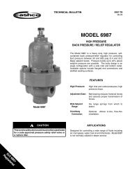
<strong>Model</strong> <strong>1078</strong><br />
04-04<br />
Valve Concepts, Inc.<br />
<strong>Model</strong> <strong>1078</strong><br />
Vacu-Gard ® Tank Blanketing Valve<br />
1” & 2” (DN25 & DN50)<br />
The <strong>Model</strong> <strong>1078</strong> is a pilot-operated valve specifi cally<br />
designed for tank blanketing. It opens and closes automatically<br />
as required, to maintain a closely controlled blanket<br />
pressure. The simple design, increases reliability and<br />
lowers maintenance cost.<br />
BENEFITS<br />
● Lower maintenance costs due to fewer parts<br />
● Inexpensive replacement parts<br />
1" <strong>Model</strong> <strong>1078</strong><br />
U.S. Pat. No. 4991620, 5067522 and 5034267<br />
TYPICAL APPLICATIONS<br />
● Blanketing of medium and large tanks<br />
● Standard valve material provides added corrosion<br />
protection at no additional cost<br />
● Valve design ensures integrity and protects against<br />
injury to personnel<br />
● Bubble tight at set point prevents waste of blanketing<br />
gases<br />
FEATURES<br />
● Single valve system<br />
● Compact & light weight<br />
● Pressure-balanced pilot<br />
● Supply pressure fl uctuations do not affect set point<br />
● Uses standard o-rings<br />
● Top entry design for easy maintenance<br />
● Set points from vacuum to 14 psig<br />
● Self cleaning fl ow design of main valve and pilot<br />
● Temperature changes have no appreciable effect on<br />
set point
GENERAL SPECIFICATIONS<br />
1” (DN25)<br />
2" (DN50)<br />
Sizes<br />
Connections<br />
1" & 2" FNPT (screwed)<br />
1" & 2" 150# & 300# RF threaded flanges with nipples<br />
1" & 2" 150# & 300# RF weldneck fl anges<br />
DN25 (PN40) & DN50 (PN40) weldneck flanges<br />
Any combination of above<br />
Larger size reducing flanges are available on request.<br />
Outlet Configurations<br />
Horizontal or Vertical<br />
Valves with FNPT or nipple and threaded fl ange<br />
connections can be configured in the field. Valves with<br />
weldneck fl ange connections, confi guration must be<br />
specifi ed at time of order.<br />
Sensing Options<br />
Remote sensing<br />
Integral dip tube sensing<br />
Supply Pressures<br />
Minimum: 20 psig (1.83 Bar)<br />
Maximum: 200 psig (13.83 Bar)<br />
See Table 6<br />
See Table 3<br />
Capacities<br />
Outlet Pressure Ranges<br />
Materials of Construction<br />
Body Material:<br />
316 SST<br />
Carbon Steel (only available on 2")<br />
Diaphragm Case Material:<br />
Carbon Steel<br />
316 SST<br />
Trim Material:<br />
316 SST<br />
Diaphragm Material:<br />
Tefl on ®<br />
Soft Seat & Seals:<br />
Fluorocarbon Elastomer – standard, Buna-N,<br />
Chemraz ® , EPDM or Kalrez ®<br />
On request elastomers to FDA requirements<br />
Temperature Limits<br />
Fluorocarbon Elastomer – (FKM)<br />
0° to 212° F (-17° to 100° C)<br />
Buna-N (Nitrile-NBR):<br />
-40° F to 180° F (-40° C to 82° C)<br />
EPDM (Ethylenepropylene):<br />
-50° F to 212° F (-45° C to 100° C)<br />
Chemraz ® (Perfl uoroelastomer-FFKM):<br />
0° F to 212° F (-18° C to 100° C)<br />
Kalrez ® (Perfl uoroelastomer-FFKM):<br />
0° to 212° F (-18° to 100° C)<br />
Approximate Weights<br />
1" <strong>Model</strong> <strong>1078</strong> FNPT:<br />
18 lbs (8.2 kg)<br />
2" <strong>Model</strong> <strong>1078</strong> FNPT:<br />
43 lbs (20 kg)<br />
1" <strong>Model</strong> <strong>1078</strong> Flanged:<br />
23 lbs (10.5 kg)<br />
2" <strong>Model</strong> <strong>1078</strong> Flanged:<br />
55 lbs (25 kg)<br />
Maximum Back Pressures<br />
25 psig (1.7 Bar) – standard<br />
Higher pressures on request<br />
2 <strong>1078</strong>-TB
CAPACITY REQUIREMENTS<br />
The capacity requirement of the tank blanketing<br />
valve is the sum of two components. The fi rst being<br />
inbreathing due to liquid or product movement out<br />
of the tank and the second being inbreathing due to<br />
contraction of the vapors/product because of weather<br />
changes.<br />
Inbreathing due to maximum liquid or product<br />
movement out of the tank equals 8.0 SCFH of air<br />
for each US gallon per minute of maximum emptying<br />
rate or 0.94 Nm 3 /h of air for each m 3 /h of maximum<br />
emptying rate.<br />
The second component, inbreathing due to<br />
weather changes, is selected from Table 5 (Table<br />
5A). The tank capacity is found in column 1 and the<br />
corresponding inbreathing requirement is selected<br />
from column 2.<br />
The two components are added together to give<br />
the total inbreathing requirement and the capacity<br />
requirement of the tank blanketing valve.<br />
Q total = Q displacement + Q thermal<br />
Q displacement (SCFH) = Max. Pumpout Rate (gpm) x 8.0<br />
or<br />
Q displacement (Nm 3 /h) = Max. Pumpout Rate (m 3 /h) x .94<br />
VALVE SELECTION<br />
If the tank blanketing supply pressure varies,<br />
use the minimum supply pressure in selecting the<br />
tank blanketing valve and the maximum supply pressure<br />
to determine blanketing valve failure capacity.<br />
Using the minimum supply pressure select the size<br />
valve from Table 6 that will meet the Total Inbreathing<br />
Requirement (Q total). Next determine if a reducing<br />
"fl ow plug" can be used to make the capacity of the<br />
tank blanketing valve more closely match the inbreathing<br />
requirements. This will also reduce the fail<br />
open capacity of the blanketing valve. This is done by<br />
dividing the required inbreathing (Q total) by the full<br />
capacity of the size valve selected and multiplying by<br />
100. Now from Table 2 choose the fl ow plug that is<br />
greater than the calculated percentage.<br />
Example:<br />
Total inbreathing requirement (Q total) = 25,850 SCFH<br />
Maximum supply pressure = 100 psig<br />
Minimum supply pressure = 80 psig<br />
Next divide the total inbreathing requirement of<br />
25,850 SCFH by the 1" valve capacity of 35,990<br />
SCFH (at 80 psig) and multiply by 100.<br />
(25,850 SCFH / 35,990 SCFH) x 100 = 71.8%<br />
From Table 2 a 75% fl ow plug would be chosen<br />
for a 1" valve. With the 75% fl ow plug the blanketing<br />
valve will fl ow 26,993 SCFH at 80 psig and at<br />
the maximum supply pressure of 100 psig it will<br />
fl ow 32,693 SCFH. The 32,693 SCFH also represents<br />
the fail open fl ow of the blanketing valve<br />
and will be used in sizing the pressure relieving<br />
device.<br />
NORMAL INSTALLATION<br />
<strong>1078</strong>-TB 3
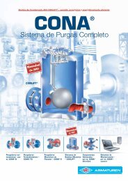
VALVE OPERATION<br />
Closed Position<br />
Figure 1 shows the Vacu-Gard ® in the closed position.<br />
This occurs when the tank pressure satisfi es<br />
or exceeds the set pressure of the pilot. When the<br />
sensed pressure is suffi cient to overcome the downward<br />
force of the set pressure spring, the pilot will<br />
close and there is no fl ow out of the pilot. This causes<br />
full supply pressure to accumulate in the chamber<br />
above the main valve piston. Since the piston area is<br />
larger than the seat area at the lower end of the piston,<br />
when the pressure above the piston is equal to<br />
the supply pressure the piston will move downward<br />
to close the valve due to the presence of a higher<br />
downward force.<br />
Figure 1<br />
Open Position<br />
Figure 2 shows the Vacu-Gard ® in the open position.<br />
When the tank pressure, that is sensed in the<br />
sense chamber below the diaphragm, is insuffi cient<br />
to hold against the downward force of the set pressure<br />
spring, the spindle in the pilot chamber will be<br />
forced downward. As the spindle unseats, the pressure<br />
in the pilot chamber will be discharged into the<br />
outlet of the valve. A small orifi ce restricts the gas<br />
fl ow into the pilot chamber from the supply pressure.<br />
Therefore, as soon as the pilot spindle opens, the<br />
pilot chamber pressure will drop signifi cantly and will<br />
not be able to hold the main valve piston down. The<br />
piston will now be pushed full open by the supply<br />
pressure, allowing a maximum fl ow of the blanketing<br />
gas into the tank.<br />
Once the tank pressure is back to set point, the<br />
spindle will close and the pilot pressure will rise to full<br />
supply pressure, pushing the main valve piston back<br />
down into the fully closed position.<br />
Figure 2<br />
4<br />
<strong>1078</strong>-TB
VALVE<br />
SIZE<br />
1" Std<br />
Valve<br />
2" Std<br />
Valve<br />
1" SST<br />
Valve<br />
2" SST<br />
Valve<br />
MAIN<br />
BODY<br />
PILOT<br />
BODY<br />
TABLE 1<br />
STANDARD MATERIALS OF CONSTRUCTION<br />
DIAPHRAGM<br />
CASE<br />
SPRING<br />
BONNET<br />
VALVE<br />
TRIM<br />
SENSE<br />
DIAPHRAGM<br />
SPRING<br />
(3 places)<br />
TUBING<br />
FITTINGS<br />
316 SST 303 SST CS CS 316 SST Tefl on ® 316 SST CS<br />
CS 303 SST CS CS 316 SST Tefl on ® 316 SST CS<br />
316 SST 316 SST 316 SST 316 SST 316 SST Tefl on ® 316 SST 316 SST<br />
316 SST 316 SST 316 SST 316 SST 316 SST Tefl on ® 316 SST 316 SST<br />
Other material combinations are available upon request.<br />
TUBING<br />
304<br />
SST<br />
304<br />
SST<br />
316<br />
SST<br />
316<br />
SST<br />
TABLE 2<br />
AVAILABLE FLOW PLUG SIZES<br />
FLOW PLUG<br />
PERCENTAGE (%)<br />
1" MODEL <strong>1078</strong> 2" MODEL <strong>1078</strong><br />
100 X X<br />
80 X<br />
75 X<br />
60 X<br />
50 X<br />
40 X<br />
25 X<br />
20 X<br />
10 X<br />
"X" Indicate available fl ow plug – additional sizes available on request.<br />
TABLE 3<br />
OUTLET PRESSURE RANGES<br />
OUTLET PRESSURE<br />
RANGES<br />
SPRING COLOR<br />
0" to 5" WC Yellow<br />
5" to 14" WC White<br />
14" to 30" WC Black<br />
1.0 to 1.5 psig Red<br />
1.5 to 3.0 psig Red<br />
3.0 to 14.0 psig Red<br />
0" to 1-1/2" WC (vac) Yellow<br />
1-1/2" to 6" WC (vac) Yellow<br />
* Other spring ranges available upon request.<br />
TABLE 4<br />
FLOW COEFFICIENTS FOR RELIEF SIZING WIDE-OPEN Cv<br />
FLOW PLUG<br />
PERCENTAGE (%)<br />
1" MODEL <strong>1078</strong> 2" MODEL <strong>1078</strong><br />
100 11.1 48<br />
80 38<br />
75 8.3<br />
60 29<br />
50 5.6<br />
40 19<br />
25 2.8<br />
20 10<br />
10 1.1<br />
<strong>1078</strong>-TB 5
The tank blanketing valve is not a substitute<br />
for the vacuum relief device.<br />
API Standard 2000 states, "The design of a gasrepressuring<br />
system to eliminate the requirement for<br />
vacuum relief valves is beyond the scope of<br />
this standard and should be considered only<br />
when the induction of air represents a hazard<br />
equal to or greater than failure of the tank".<br />
The tank blanketing valve failure must be<br />
taken into account when considering possible<br />
causes of overpressure in a tank.<br />
API Standard 2000 states, "When the possible<br />
causes of overpressure or vacuum in a tank are being<br />
determined, other circumstances resulting from<br />
equipment failures and operating errors must be<br />
considered and evaluated by the designer." Failure<br />
of the tank blanketing valve can result in unrestricted<br />
gas fl ow into the tank, reduced gas fl ow or complete<br />
loss of the gas fl ow.<br />
Tank blanketing valve set point definition is<br />
not the same for all manufacturers.<br />
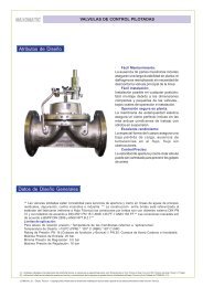
STANDARD INFORMATION<br />
+ 2"<br />
+ 1"<br />
0 ATM<br />
ADDITIONAL FEATURES<br />
Valve Concepts defi nes set point as the point<br />
where the tank blanketing valve is closed bubble<br />
tight!<br />
Some manufacturers defi ne the set point as<br />
where the blanketing valve opens and the valve<br />
requires a pressure above the set point in order to<br />
close completely. Others defi ne set point somewhere<br />
in between opening and closing but still the pressure<br />
must go above the defined set point in order to close<br />
completely.<br />
The following example illustrates Valve Concepts<br />
defi nition of set point:<br />
DEAD BAND<br />
Relief Vent Set Point<br />
VCI Set Point<br />
Vacu-Gard wide open<br />
As can be seen from the illustration, the Vacu-<br />
Gard gives the greatest dead band between the blanketing<br />
valve set point and the relief vent set point.<br />
Maintenance View Point:<br />
The Vacu-Gard ® Tank Blanketing Valve was<br />
designed for years of maintenance free operation<br />
and has years of proven fi eld experience. In fact the<br />
fi rst valve ever manufactured is still in service! But if<br />
service should be required the Vacu-Gard ® makes it<br />
easy. Here are just a few points:<br />
• Every bolt on the Vacu-Gard ® is identical; in fact,<br />
every nut, fl at washer and lock washer is identical.<br />
• All seats and seals are standard o-rings. This makes<br />
repair kits inexpensive and readily available.<br />
• The Vacu-Gard ® has a top entry design. This allows<br />
complete access to the valve without being removed<br />
from the tank.<br />
Application View Point:<br />
The Vacu-Gard ® Tank Blanketing Valve was<br />
designed to reduce blanketing gas losses on lowpressure<br />
storage tanks, provide fl exibility to fi t the<br />
application and simplify the selection process.<br />
• On many low-pressure storage tanks the operating<br />
range is very low, which makes blanketing and venting<br />
system selection/design a challenge for the engineer.<br />
The Vacu-Gard ® makes the job much easier.<br />
First, the Vacu-Gard ® set point defi nition is where the<br />
blanketing valve closes bubble tight. This gives the<br />
largest dead band between the blanketing valve set<br />
point and the set point of the relieving device, and<br />
therefore will reduce losses. Second, the Vacu-Gard ®<br />
has a wide range of available settings, from vacuum<br />
to 14 psig, that make proper selection easier.<br />
• The only time the diaphragm case needs to be disassembled<br />
is when replacing the diaphragm. Every<br />
part of the main valve and every part of the pilot assembly<br />
can be accessed without disassembling the<br />
diaphragm case.<br />
• Because the Vacu-Gard ® uses standard o-rings,<br />
selection of the proper elastomers for the application<br />
is easy and inexpensive.<br />
• The Vacu-Gard ® offers a wide variety of confi gurations<br />
to meet every blanketing application.<br />
• The valve set point and performance can be verifi ed<br />
100% on the tank, without removal and without fl owing<br />
supply gas into the tank.<br />
6 <strong>1078</strong>-TB
TABLE 5<br />
REQUIREMENTS FOR THERMAL INBREATHING - ENGLISH UNITS<br />
(Column 1) (Column 2) (Column 1) (Column 2)<br />
TANK CAPACITY INBREATHING TANK CAPACITY INBREATHING<br />
Barrels Gallons SCFH Air Barrels Gallons SCFH Air<br />
60 2,500 60 35,000 1,470,000 31,000<br />
100 4,200 100 40,000 1,680,000 34,000<br />
500 21,000 500 45,000 1,890,000 37,000<br />
1,000 42,000 1,000 50,000 2,100,000 40,000<br />
2,000 84,000 2,000 60,000 2,520,000 44,000<br />
3,000 126,000 3,000 70,000 2,940,000 48,000<br />
4,000 168,000 4,000 80,000 3,360,000 52,000<br />
5,000 210,000 5,000 90,000 3,780,000 56,000<br />
10,000 420,000 10,000 100,000 4,200,000 60,000<br />
15,000 630,000 15,000 120,000 5,040,000 68,000<br />
20,000 840,000 20,000 140,000 5,880,000 75,000<br />
25,000 1,050,000 24,000 160,000 6,720,000 82,000<br />
30,000 1,260,000 28,000 180,000 7,560,000 90,000<br />
NOTE: Table and sizing from API 2000 fi fth edition, April 1998.<br />
TABLE 5A<br />
REQUIREMENTS FOR THERMAL INBREATHING - METRIC UNITS<br />
(Column 1) (Column 2) (Column 1) (Column 2)<br />
TANK CAPACITY INBREATHING TANK CAPACITY INBREATHING<br />
CUBIC METERS Nm3/H CUBIC METERS Nm3/H<br />
10 1.69 5000 787<br />
20 3.37 6000 896<br />
100 16.9 7000 1003<br />
200 33.7 8000 1077<br />
300 50.6 9000 1136<br />
500 84.3 10000 1210<br />
700 118 12000 1345<br />
1000 169 14000 1480<br />
1500 253 16000 1615<br />
2000 337 18000 1745<br />
3000 506 20000 1877<br />
3180 536 25000 2179<br />
4000 647 30000 2495<br />
NOTE: Table and sizing from API 2000 fi fth edition, April 1998.<br />
<strong>1078</strong>-TB 7
TABLE 6<br />
TANK BLANKETING VALVE CAPACITIES<br />
INLET PRESSURE CAPACITIES IN SCFH (Nm 3 /h) OF AIR<br />
psig (Bar) 1" MODEL <strong>1078</strong> 2" MODEL <strong>1078</strong><br />
20 (1.4) 13,188 (353) 57,186 (1533)<br />
30 (2.1) 16,990 (455) 73,666 (1974)<br />
40 (2.8) 20,790 (557) 90,146 (2416)<br />
50 (3.4) 24,590 (659) 106,626 (2858)<br />
60 (4.1) 28,390 (761) 123,106 (3299)<br />
70 (4.8) 32,190 (863) 139,586 (3741)<br />
80 (5.5) 35,990 (965) 156,066 (4183)<br />
90 (6.2) 39,790 (1066) 172,546 (4624)<br />
100 (6.9) 43,590 (1168) 189,026 (5066)<br />
110 (7.6) 47,390 (1270) 205,506 (5508)<br />
120 (8.3) 51,190 (1372) 221,986 (5949)<br />
130 (9.0) 54,990 (1474) 238,466 (6391)<br />
140 (9.6) 58,790 (1576) 254,949 (6833)<br />
150 (10.3) 62,590 (1677) 271,426 (7274)<br />
160 (11.0) 66,390 (1779) 287,906 (7716)<br />
170 (11.7) 70,190 (1881) 304,386 (8158)<br />
180 (12.4) 73,990 (1983) 320,866 (8599)<br />
190 (13.1) 77,790 (2085) 337,346 (9041)<br />
200 (13.8) 81,590 (2187) 353,826 (9483)<br />
NOTE: To reduce fl ow capacity, use the fl ows plugs listed in Table 2.<br />
Reduced capacity will equal the fl ow plug percentage times the full fl ow<br />
capacity listed above.<br />
8 <strong>1078</strong>-TB
1" <strong>Model</strong> <strong>1078</strong> DIMENSIONS<br />
FLANGES A B C D<br />
1" - 150# RF 5.39" (136.9 mm) 3.06" (77.7 mm) 9.88" (251 mm) 3.69" (94 mm)<br />
1" - 150# SW 7.31" (185.7 mm) 5.00" (127.0 mm) 13.75" (349.3 mm) 5.63" (143 mm)<br />
1" - 300# RF 5.64" (143.3 mm) 3.31" (84.1 mm) 10.38" (264 mm) 3.94" (100 mm)<br />
1" - 300# SW 7.31" (185.7 mm) 5.00" (127.0 mm) 13.75" (349.3 mm) 5.63" (143 mm)<br />
1 1/2" - 150# RF 5.52" (140.2 mm) 3.19" (81.0 mm) 10.14" (258 mm) 3.82" (97 mm)<br />
2" - 150" RF 5.58" (141.7 mm) 3.25" (82.6 mm) 10.26" (261 mm) 3.88" (99 mm)<br />
DN25 - PN40 4.77" (121 mm) 2.45" (62.4 mm) 8.65" (220 mm) 3.07" (78.1 mm)<br />
NOTE: See pages 10 & 11 for additional 1" <strong>Model</strong> <strong>1078</strong> dimensional drawings.<br />
<strong>1078</strong>-TB 9
1" <strong>Model</strong> <strong>1078</strong> DIMENSIONS (cont.)<br />
10 <strong>1078</strong>-TB
1" <strong>Model</strong> <strong>1078</strong> DIMENSIONS (cont.)<br />
<strong>1078</strong>-TB 11
2" <strong>Model</strong> <strong>1078</strong> DIMENSIONS<br />
FLANGES A B C D<br />
2" - 150# RF 8.57" (217.6 mm) 4.90" (124.5 mm) 14.69" (373.1 mm) 5.70" (144.8 mm)<br />
2" - 300# RF 8.82" (224.0 mm) 5.15" (130.8 mm) 15.19" (385.8 mm) 5.95" (151.1 mm)<br />
DN50 - PN40 7.96" (202 mm) 4.29" (109 mm) 13.5" (342 mm) 5.09" (129 mm)<br />
NOTE: See page 13 for additional 2" <strong>Model</strong> <strong>1078</strong> dimensional drawing.<br />
12 <strong>1078</strong>-TB
2" <strong>Model</strong> <strong>1078</strong> DIMENSIONS (cont.)<br />
<strong>1078</strong>-TB 13
OPTIONAL FEATURES & ACCESSORIES<br />
Supply Pressure Gauge<br />
To provide local indication of supply pressure.<br />
• Standard ABS gauge with carbon steel fi tting.<br />
• Stainless gauge with 316 SST fi tting.<br />
Control Pressure Gauge<br />
To provide local indication of actual tank pressure.<br />
Sense with Dip Tube (patented)<br />
This option provides a sense connection into the<br />
tank through the vertical outlet of the valve. This can<br />
be useful when no tank connection is available for<br />
the standard external sense.<br />
The dip tube length should be sized so that it<br />
protrudes 6" to 8" below the tank roof into the tank.<br />
• Standard material is 316 SST.<br />
• Standard Magnehelic ® gauge with carbon steel<br />
fi tting.<br />
• Stainless gauge with 316 SST fi tting.<br />
Purge<br />
A purge is used to prevent tank vapors from entering<br />
into the valve, specifi cally the pilot. One Variable<br />
Area Flow meter (Rotameter) is used to purge<br />
both the sense line and the outlet. The combined<br />
fl ow is 1 - 1.5 SCFH. VCI advises the use of a purge<br />
when tank vapors may solidify or crystallize when<br />
cooled to ambient temperature.<br />
A purge will also extend the service life of the<br />
valve if 316 SST is not compatible with the tank vapors.<br />
• Standard Rotameter used has a 316 SST body<br />
with glass tube.<br />
PV-Gard Manifold<br />
The PV-Manifold allows for a very compact installation<br />
of a blanketing valve and vent valve on one<br />
single tank nozzle. Normally, an installation of this<br />
type requires at least three different nozzles; one for<br />
the blanketing valve, one for the vent valve, and one<br />
for the remote sensing for the blanketing valve. Using<br />
the PV-Manifold, only one tank nozzle is required.<br />
Inline Filter<br />
The valve comes standard with a pre-fi ter and a<br />
pilot fi lter in the pilot supply line. Therefore the use<br />
of an inline fi lter is not required for regular blanketing<br />
gases. An inline strainer or fi lter can be provided on<br />
request.<br />
14 <strong>1078</strong>-TB
1" <strong>Model</strong> <strong>1078</strong> PRODUCT CODE<br />
4/05/04<br />
TABLE 4 - End Connections<br />
END CONNECTION<br />
CODE<br />
1 " FNPT T<br />
1" 150# SW Flanges w/ nipples C<br />
TABLE 3 - Materials<br />
BODY MATERIALS<br />
CODE<br />
316 SST Body w/ 316 SST Trim & CS Diaphragm Case C<br />
316 SST Body, Trim & Diaphragm Case S<br />
316 SST Body w/ 316 SST Trim, All Wetted Surfaces SST W<br />
1" 300# SW Flanges w/ nipples H<br />
1" 150# RF Flanges w/ nipples A<br />
1" 300# RF Flanges w/ nipples B<br />
1" 150# RF Weldneck Flanges D<br />
1" 300# RF Weldneck Flanges E<br />
2" 150# RF Weldneck Flanges F<br />
DIN DN25 PN40<br />
Weldneck Flanges<br />
M<br />
Consult factory for other connections.<br />
TABLE 5 - Flow Plug Size<br />
OPTION<br />
CODE<br />
TABLE 2 - Sensing<br />
MATERIALS<br />
CODE<br />
Integral Dip Tube Sensing<br />
(vertical outlet only)<br />
6<br />
Remote Sensing 7<br />
10% 1<br />
25% 2<br />
50% 5<br />
75% 7<br />
100% X<br />
TABLE 6 - Seats & Seals<br />
TABLE 1 - Outlet<br />
OUTLET CODE<br />
Horizontal H<br />
Vertical V<br />
MATERIAL<br />
Buna-N<br />
Chemraz ®<br />
EPDM<br />
Kalrez ®<br />
Fluorocarbon<br />
Elastomer<br />
CODE<br />
B<br />
C<br />
E<br />
K<br />
V<br />
P<br />
1<br />
1<br />
1" <strong>1078</strong> PILOT OPERATED VACU-GARD ®<br />
CODER SHEET<br />
TABLE 7 - Range Springs<br />
SPRING RANGE<br />
CODE<br />
0"-5.0" wc (0-12.4 mbar) 3<br />
5"-14" wc (12.4-34.8 mbar) 6<br />
14"-30" wc (34.8-74.7 mbar) 7<br />
1-1.5 psig (69-103 mbar) 8<br />
1.5-3 psig (103-207 mbar) 9<br />
3-14 psig (0.2-0.96 bar) H<br />
0" - 1.5" wc vac (0-3.7 mbar) A<br />
1.5"-6" wc vac (3.7-14.8 mbar) C<br />
* Other spring ranges available upon request.<br />
TABLE 8 - External Pilot Filter<br />
DESCRIPTION<br />
SST Filter with purge<br />
Aluminum Filter<br />
Alum/Zinc Filter w/ backfl ow preventer check valve<br />
SST Filter w/ backfl ow preventer check valve<br />
Alum/Zinc Filter with purge<br />
SST Filter<br />
Alum/Zinc Filter<br />
CODE<br />
A<br />
B<br />
C<br />
D<br />
P<br />
S<br />
W<br />
<strong>1078</strong>-TB 15
2" <strong>Model</strong> <strong>1078</strong> PRODUCT CODE<br />
4/05/04<br />
TABLE 4 - End Connections<br />
END CONNECTION<br />
FNPT<br />
CODE<br />
T<br />
150# SW Flanges w/ nipples C<br />
TABLE 3 - Materials<br />
BODY MATERIALS<br />
CS Body w/ 316 SST Trim & CS Diaphragm Case<br />
CODE<br />
C<br />
150# RF Weldneck Flanges D<br />
300# SW Flanges w/ nipples H<br />
300# RF Weldneck Flanges E<br />
316 SST Body, Trim & Diaphragm Case S<br />
316 SS Body w/ 316 SST Trim, All Wetted Surfaces SST W<br />
DIN DN50 PN40<br />
Weldneck Flanges<br />
Consult factory for other connections.<br />
M<br />
TABLE 5 - Flow Plug Size<br />
OPTION<br />
CODE<br />
TABLE 2 - Sensing<br />
MATERIALS<br />
Integral Dip Tube Sensing<br />
(vertical outlet only)<br />
CODE<br />
6<br />
20% D<br />
40% 4<br />
60% 6<br />
80% 8<br />
100% X<br />
Remote Sensing 7<br />
TABLE 6 - Seats & Seals<br />
TABLE 1 - Outlet<br />
OUTLET CODE<br />
Horizontal<br />
H<br />
Vertical<br />
V<br />
MATERIAL<br />
Buna-N<br />
Chemraz ®<br />
EPDM<br />
Kalrez ®<br />
Fluorocarbon<br />
Elastomer<br />
CODE<br />
B<br />
C<br />
E<br />
K<br />
V<br />
P<br />
2<br />
2<br />
2" <strong>1078</strong> PILOT OPERATED VACU-GARD ®<br />
CODER SHEET<br />
TABLE 7 - Range Springs<br />
SPRING RANGE<br />
CODE<br />
0"-5.0" wc (0-12.4 mbar) 3<br />
5"-14" wc (12.4-34.8 mbar) 6<br />
14"-30" wc (34.8-74.7 mbar) 7<br />
1-1.5 psig (69-103 mbar) 8<br />
1.5-3 psig (103-207 mbar) 9<br />
3-14 psig (0.2-0.96 bar) H<br />
TABLE 8 - External Pilot Filter<br />
DESCRIPTION<br />
SST External Pilot Filter with purge<br />
Aluminum Filter<br />
Alum/Zinc Filter w/ backfl ow preventer check valve<br />
SST Filter w/ backfl ow preventer check valve<br />
Alum/Zinc Filter with purge<br />
SST Filter<br />
Alum/Zinc Filter<br />
CODE<br />
A<br />
B<br />
C<br />
D<br />
P<br />
S<br />
W<br />
Valve Concepts, Inc.<br />
3644 Westchase Drive<br />
Houston, TX 77042-5224<br />
PH (713) 271-7171<br />
Fax. # (713) 271-0153<br />
www.valveconcepts.com<br />
email: vcisales@cashco.com<br />
Printed in U.S.A. <strong>Model</strong> <strong>1078</strong> – 1" & 2" TB<br />
0" - 1.5" wc vac (0-3.7 mbar) A<br />
1.5"-6" wc vac (3.7-14.8 mbar) C<br />
* Other spring ranges available upon request.