Field Service Procedure - Replacement Pol Pot Kit, 6006C, 6009C ...
Field Service Procedure - Replacement Pol Pot Kit, 6006C, 6009C ...
Field Service Procedure - Replacement Pol Pot Kit, 6006C, 6009C ...

You also want an ePaper? Increase the reach of your titles
YUMPU automatically turns print PDFs into web optimized ePapers that Google loves.
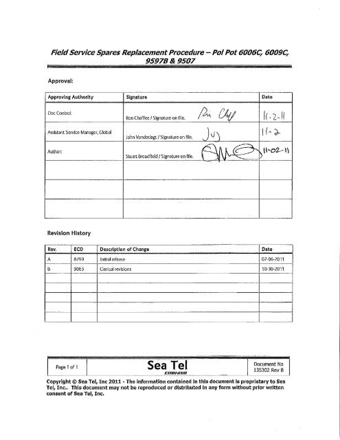
<strong>Field</strong> <strong>Service</strong> <strong>Procedure</strong> - <strong>Replacement</strong> <strong>Pol</strong> <strong>Pot</strong> <strong>Kit</strong>, <strong>6006C</strong>, <strong>6009C</strong>,<br />
9597B & 9507<br />
1. Brief Summary:<br />
Troubleshooting document for diagnosing a fault with and replacing the pol pot on the <strong>6006C</strong>, <strong>6009C</strong>, 9597B and<br />
9507series antennas.<br />
2. Checklist:<br />
<br />
<br />
<br />
Verify Range of Motion<br />
Verify <strong>Pot</strong> Feedback<br />
Measure Resistance<br />
3. Theory of Operation:<br />
A polang potentiometer is used to provide a feedback reference for the position of the feed assembly for linear<br />
polarization. The pot acts as a potential divider giving an output voltage which varies from 0Vdc to 5Vdc. The PCU<br />
converts the voltage output from the pot into the numerical value displayed on the DAC. A failure with the pot causing it<br />
to output an incorrect voltage, will result in the feed assembly not being aligned correctly causing bad cross pol isolation.<br />
One indication that there is a fault with the feed alignment of the system is that the target light will be permanently<br />
illuminated on the DAC and the antenna won’t target correctly. It will sit 8 degrees above (or 8 degrees below at high<br />
elevations) the satellites elevation look angle. As part of the antennas targeting procedure the system will calculate the<br />
threshold value based on the noise floor level and then align the feed for the correct reception position based on the<br />
vessels GPS position and the lookup table in the DAC.<br />
If the system is unable to drive the pol motor to obtain the correct feedback, or if the pot has failed and won’t give the<br />
correct feedback, the antenna can’t complete the target process and the antenna will stay in this position. Setting the pol<br />
type to “0009” will make the antenna target by removing the auto pol function from the targeting process; however the<br />
miss alignment of the feed will cause bad cross pol isolation.<br />
4. Verify Range of Motion:<br />
First verify the settings in the DAC are correct, the pol scale should be set to 0090 to give the feed 180 degrees of motion.<br />
The default pol offset is 0030 (however these may have been modified slightly to “trim” the pol angle). Turn tracking off<br />
(if applicable) and drive the elevation to 0 degrees to make it easier to view the feed assembly for diagnostic purposes.<br />
Set the pol type setting in the setup menu of the DAC to “0009” to set the mode of the pol assembly from automatic to<br />
manual. Now enter the pol window (after the relative window in the “antenna” screen of the DAC) and hold the down<br />
arrow to drive the feed assembly into its end stop. At the lower end of the range the pol count should be approximately<br />
28, at which point the polang stop plate on the feed should be horizontal facing to the right (when looking face onto the<br />
feed).<br />
If no pol motor drive is present verify the pol reading on the DAC isn’t out of range (i.e. displaying a value of either 0 or<br />
255). If one of these values are displayed its possible the pot isn’t aligned correctly and that adjusting it may bring it back<br />
with its range of operation. Back the pot off from the main gear sprocket and rotate its pulley, verify that the feedback<br />
value changes on the DAC. If so, calibrate the pol pot and verify operation as described in the later stages of this<br />
document. If the pol count on the DAC doesn’t change when the pot is adjusted the pot has failed and is outputting a<br />
default value. See Verifying the Resistance of the <strong>Pol</strong> <strong>Pot</strong> section below. If this is the case no drive will be issued to the<br />
pol motor as the value is out of the range which the system operates in.<br />
Page 1 of 7<br />
Document No<br />
135302 Rev B<br />
Copyright © Sea Tel, Inc 2011 - The information contained in this document is proprietary to Sea<br />
Tel, Inc.. This document may not be reproduced or distributed in any form without prior written<br />
consent of Sea Tel, Inc.
<strong>Field</strong> <strong>Service</strong> <strong>Procedure</strong> - <strong>Replacement</strong> <strong>Pol</strong> <strong>Pot</strong> <strong>Kit</strong>, <strong>6006C</strong>, <strong>6009C</strong>,<br />
9597B & 9507<br />
5. Verify the Resistance of the <strong>Pol</strong> <strong>Pot</strong>:<br />
The polang potentiometer (pol pot) consists of an internal slider as well as a CW and CCW contact. To verify the<br />
resistance of the pot a multi meter can be used to measure between the slider and one of the wipers whilst rotating the<br />
shaft through its range and verifying the 0 – 5K ohms is outputted correctly. Disconnect J1 from motor termination PCB<br />
assembly.<br />
Looking down onto the shaft of the pot rotate it clockwise until<br />
it reaches its end stop.<br />
Now measure the resistance between the slider and the CW<br />
contact (red cable, pin 3 on the IDC connector and the grey cable<br />
pin 2 on the IDC connector).<br />
The feedback should be approximately 0k ohms.<br />
Now slowly rotate the shaft of the pot counter clockwise, the<br />
reading should count up sequentially. After five turns the pot will<br />
be in the centre of its range giving a resistance of approximately<br />
25k ohms.<br />
Continue to rotate the pot until the counter clockwise end stop<br />
(it will now have turned through all 10 rotations of its range), the<br />
resistance should be approximately 5k ohms.<br />
Leaving the pot at its counter clockwise end stop measure between the clockwise contact and the slider (grey cable, pin 2<br />
on the IDC connector and the brown cable pin 1 on the IDC connector) the resistance should be reversed from the<br />
previous rotation, reading 0 ohms. Rotating the shaft of the pot clockwise should increase the resistance through its<br />
range to 5k ohms. Any error with the pot not giving the correct resistance is an indication the pot is defective and needs<br />
replacing.<br />
Page 2 of 7<br />
Document No<br />
135302 Rev B<br />
Copyright © Sea Tel, Inc 2011 - The information contained in this document is proprietary to Sea<br />
Tel, Inc.. This document may not be reproduced or distributed in any form without prior written<br />
consent of Sea Tel, Inc.
<strong>Field</strong> <strong>Service</strong> <strong>Procedure</strong> - <strong>Replacement</strong> <strong>Pol</strong> <strong>Pot</strong> <strong>Kit</strong>, <strong>6006C</strong>, <strong>6009C</strong>,<br />
9597B & 9507<br />
6. <strong>Pol</strong> <strong>Pot</strong> <strong>Replacement</strong> <strong>Procedure</strong>:<br />
6.1. Tools.<br />
Snips/Cutters<br />
9/64” Allen Wrench/Key<br />
3/32” Allen Wrench/Key<br />
12mm Wrench/Spanner<br />
Loctite 222, 242 and 638<br />
Cable Ties<br />
6.2. <strong>Procedure</strong>.<br />
<strong>Procedure</strong> for replacing the <strong>Pol</strong> <strong>Pot</strong> on the <strong>6009C</strong>, 9597B and 9507 linear C‐Band systems, Sea Tel kit part number:<br />
134919 (pot part number: 115425‐5).<br />
*CAUTION: Power down the pedestal before following this<br />
procedure.<br />
1. Cut the cable ties securing the pol pot harness.<br />
2. Disconnect the pol pot IDC connector from the termination<br />
block.<br />
3. Using a 9/64” Allen wrench, remove the pot assembly from the<br />
feed.<br />
Page 3 of 7<br />
Document No<br />
135302 Rev B<br />
Copyright © Sea Tel, Inc 2011 - The information contained in this document is proprietary to Sea<br />
Tel, Inc.. This document may not be reproduced or distributed in any form without prior written<br />
consent of Sea Tel, Inc.
<strong>Field</strong> <strong>Service</strong> <strong>Procedure</strong> - <strong>Replacement</strong> <strong>Pol</strong> <strong>Pot</strong> <strong>Kit</strong>, <strong>6006C</strong>, <strong>6009C</strong>,<br />
9597B & 9507<br />
4. Install the mounting bracket onto the pol pot using a 12mm<br />
wrench.<br />
5. Apply Loctite 638 to the shaft of the pot and install the pulley,<br />
apply Loctite 222 to the set screw and install using a 3/32” Allen<br />
wrench.<br />
6. Apply Loctite 242 to the mounting screw and install the<br />
replacement pol pot assembly. Do not fully engage at this time.<br />
7. Secure the pol pot harness with cable ties and reconnect the<br />
IDC connector.<br />
8. Follow the below procedure for calibrating the pot.<br />
Page 4 of 7<br />
Document No<br />
135302 Rev B<br />
Copyright © Sea Tel, Inc 2011 - The information contained in this document is proprietary to Sea<br />
Tel, Inc.. This document may not be reproduced or distributed in any form without prior written<br />
consent of Sea Tel, Inc.
<strong>Field</strong> <strong>Service</strong> <strong>Procedure</strong> - <strong>Replacement</strong> <strong>Pol</strong> <strong>Pot</strong> <strong>Kit</strong>, <strong>6006C</strong>, <strong>6009C</strong>,<br />
9597B & 9507<br />
7. <strong>Pol</strong> <strong>Pot</strong> Alignment and Verification:<br />
1. Drive the reflector to zero degrees of elevation to view the orientation of the feed assembly:<br />
Press the button to turn the tracking function off (if applicable) to prevent the antenna from going into a<br />
search. Push the button until the ‘Antenna’ window is displayed (the screen will show the AZ, EL and REL<br />
values). Press the button twice to isolate the ‘EL’ window and then press the arrow to activate it (a cursor<br />
will be displayed). Now use the and arrow keys to scroll the cursor along and use the and arrow keys<br />
to change the elevation value to “00.0” and press the button.<br />
2. Set the <strong>Pol</strong>ang Type to manual mode:<br />
Enter the ‘Setup Menu’ mode by pressing and holding the arrow keys together until the ‘EL Trim’ or ‘Auto<br />
Trim’ window is displayed. Push the arrow key until the ‘<strong>Pol</strong>ang Type’ window is displayed. Press the arrow<br />
key to activate the window. Now use the and arrow keys to scroll the cursor along and use the and<br />
arrow keys to change the characters. Set the ‘<strong>Pol</strong>ang Type’ to “0009” which is manual mode and press the<br />
button.<br />
3. Press the button to go to the ‘<strong>Pol</strong> Offset’ window and verify the default setting is “0030” for a 9597B or 9507<br />
or “0040” for a <strong>6006C</strong> or <strong>6009C</strong>. (If necessary use arrow keys to select appropriate digits and change accordingly).<br />
4. Now keep pressing the button until the ‘Antenna’ window is displayed (the screen will show the AZ, EL and<br />
REL values).<br />
5. Press the button 4 times until ‘<strong>Pol</strong> xxx’ is displayed and then press the arrow key to activate the window.<br />
6. Now hold either the or arrow key to drive the pol until a count of either “130” for the <strong>6006C</strong> or<strong>6009C</strong>, or<br />
“120” is displayed for the 9597B and 9507 pedestals.<br />
*Note: It’s advisable to have someone watching the feed while it’s being driven as if the pot isn’t correctly<br />
calibrated there is the possibility to damage the assembly if the LNB hits the pol motor or the reflector harness is<br />
coiled around the feed.<br />
7. Observe the physical alignment of the feed:<br />
The RX waveguide should be facing downwards with the TX reject filter to the right, vertically with the LNB<br />
horizontally above the assembly with the coax exiting to the left. Later revisions of this system use an additional<br />
length of waveguide with the filter above the assembly horizontally, and the LNB facing downwards on the left side<br />
(as shown on the below image).<br />
Page 5 of 7<br />
Document No<br />
135302 Rev B<br />
Copyright © Sea Tel, Inc 2011 - The information contained in this document is proprietary to Sea<br />
Tel, Inc.. This document may not be reproduced or distributed in any form without prior written<br />
consent of Sea Tel, Inc.
<strong>Field</strong> <strong>Service</strong> <strong>Procedure</strong> - <strong>Replacement</strong> <strong>Pol</strong> <strong>Pot</strong> <strong>Kit</strong>, <strong>6006C</strong>, <strong>6009C</strong>,<br />
9597B & 9507<br />
*Note: LNB not shown for clarity.<br />
(Steps 8‐12 requires assistance to observe and operate antenna simultaneously)<br />
8. Using the DAC‐2202 drive the feed so the RX waveguide exits vertically.<br />
Press the arrow key to activate the cursor on the pol window. Now hold either the or arrow key to drive<br />
the pol motor until the RX wave guide is facing downwards. Now press the button to de‐activate the<br />
window.<br />
9. Locate the pol potentiometer on the feed and loosen the screw that secures the slotted mounting plate with a 9/64”<br />
Allen wrench and carefully move the pol pot gear out of alignment with the belt (fig. 1.1).<br />
10. Align the potentiometer:<br />
(Fig. 1.1)<br />
On the DAC verify the cursor is not displayed on the pol window, if it is press the button (failure to do this will<br />
result in display not changing). Now rotate the pot sprocket manually until a count of either 120 for the 9597B and<br />
9507 or 130 for the <strong>6006C</strong> and <strong>6009C</strong> is achieved, depending on your antenna model. Now reinstall the pot on the<br />
main sprocket.<br />
*Note: When re‐installing the pot onto the belt, it is common for the reading to change as the teeth are engaged.<br />
Once the pot had been installed recheck the pol value and adjust if necessary. Due to the belt/sprocket alignment of<br />
the pot the tolerance is +/‐ 2 degrees so 118‐122 counts for the 9597B and 9507 and 128‐132 for the <strong>6009C</strong>.<br />
Page 6 of 7<br />
Document No<br />
135302 Rev B<br />
Copyright © Sea Tel, Inc 2011 - The information contained in this document is proprietary to Sea<br />
Tel, Inc.. This document may not be reproduced or distributed in any form without prior written<br />
consent of Sea Tel, Inc.
<strong>Field</strong> <strong>Service</strong> <strong>Procedure</strong> - <strong>Replacement</strong> <strong>Pol</strong> <strong>Pot</strong> <strong>Kit</strong>, <strong>6006C</strong>, <strong>6009C</strong>,<br />
9597B & 9507<br />
11. Drive the pol motor to its upper and lower electrical limits and verify the assembly drives in the correct direction and<br />
that the feed assembly has 180 degrees of rotation:<br />
On the DAC press the arrow key to display cursor underneath the pol value and then press and hold the<br />
arrow key to drive the feed to its upper end stop. Verify the assembly drives 90 degrees so the exit of the RX wave<br />
guide is horizontal, facing the left with the LNB now vertical with the coax facing upwards (provided the LNB was<br />
horizontal in the previous step, depending on the configuration of the antenna). The pol reading should be<br />
approximately 211 counts.<br />
Now press and hold the arrow key to drive the feed to its lower end stop and verify the feed rotates 180<br />
degrees, with the exit of the RX waveguide horizontally facing the right, and the LNB now vertical with the coax<br />
facing downwards (depending on the configuration of the antenna). The pol reading should be approximately 28<br />
counts.<br />
12. Set the <strong>Pol</strong> Type to Automatic (auto pol):<br />
Press and hold the<br />
arrow keys together until the ‘EL Trim’ or ‘Auto Trim’ window is displayed. Push the<br />
arrow key to scroll through the settings until the ‘<strong>Pol</strong> Type’ window is displayed and press the arrow key to<br />
activate the window. Now use the and arrow keys to scroll the cursor along and use the and arrow<br />
keys to change the value from “0009” to “0072” and then press the button to put the system back into<br />
automatic polang (auto pol) mode.<br />
Watch the LNB and verify it returns to the correct reception position (while the pol motor is driving the target light<br />
will be illuminated on the DAC).<br />
13. Save the settings in the DAC‐2202:<br />
Press and hold the arrow keys together briefly, “Save New Parameters” will be displayed. Press the<br />
arrow key to activate the window and then press the button, “Parameters Saved” will be displayed and the<br />
pol type and pol offset will be stored in the DAC.<br />
*Note: If making adjustments to the polarization alignment of a VSAT antenna contacting the NOC to run through<br />
a cross‐pol isolation test and calibrating the <strong>Pol</strong> Offset will be necessary.<br />
Page 7 of 7<br />
Document No<br />
135302 Rev B<br />
Copyright © Sea Tel, Inc 2011 - The information contained in this document is proprietary to Sea<br />
Tel, Inc.. This document may not be reproduced or distributed in any form without prior written<br />
consent of Sea Tel, Inc.