50 MW OTEC Plantship Design - Hawaii National Marine ...
50 MW OTEC Plantship Design - Hawaii National Marine ...
50 MW OTEC Plantship Design - Hawaii National Marine ...

Create successful ePaper yourself
Turn your PDF publications into a flip-book with our unique Google optimized e-Paper software.
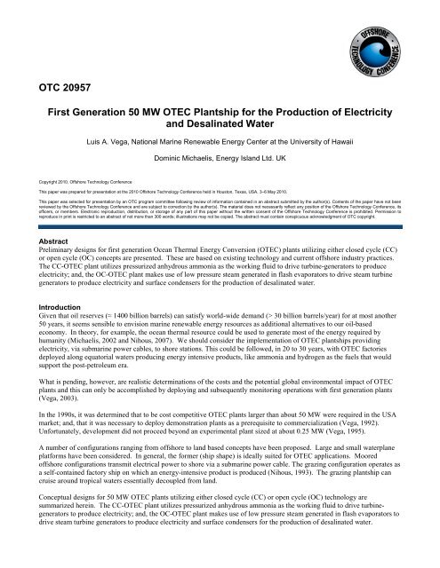
OTC 20957<br />
First Generation <strong>50</strong> <strong>MW</strong> <strong>OTEC</strong> <strong>Plantship</strong> for the Production of Electricity<br />
and Desalinated Water<br />
Luis A. Vega, <strong>National</strong> <strong>Marine</strong> Renewable Energy Center at the University of <strong>Hawaii</strong><br />
Dominic Michaelis, Energy Island Ltd. UK<br />
Copyright 2010, Offshore Technology Conference<br />
This paper was prepared for presentation at the 2010 Offshore Technology Conference held in Houston, Texas, USA, 3–6 May 2010.<br />
This paper was selected for presentation by an OTC program committee following review of information contained in an abstract submitted by the author(s). Contents of the paper have not been<br />
reviewed by the Offshore Technology Conference and are subject to correction by the author(s). The material does not necessarily reflect any position of the Offshore Technology Conference, its<br />
officers, or members. Electronic reproduction, distribution, or storage of any part of this paper without the written consent of the Offshore Technology Conference is prohibited. Permission to<br />
reproduce in print is restricted to an abstract of not more than 300 words; illustrations may not be copied. The abstract must contain conspicuous acknowledgment of OTC copyright.<br />
Abstract<br />
Preliminary designs for first generation Ocean Thermal Energy Conversion (<strong>OTEC</strong>) plants utilizing either closed cycle (CC)<br />
or open cycle (OC) concepts are presented. These are based on existing technology and current offshore industry practices.<br />
The CC-<strong>OTEC</strong> plant utilizes pressurized anhydrous ammonia as the working fluid to drive turbine-generators to produce<br />
electricity; and, the OC-<strong>OTEC</strong> plant makes use of low pressure steam generated in flash evaporators to drive steam turbine<br />
generators to produce electricity and surface condensers for the production of desalinated water.<br />
Introduction<br />
Given that oil reserves (≈ 1400 billion barrels) can satisfy world-wide demand (> 30 billion barrels/year) for at most another<br />
<strong>50</strong> years, it seems sensible to envision marine renewable energy resources as additional alternatives to our oil-based<br />
economy. In theory, for example, the ocean thermal resource could be used to generate most of the energy required by<br />
humanity (Michaelis, 2002 and Nihous, 2007). We should consider the implementation of <strong>OTEC</strong> plantships providing<br />
electricity, via submarine power cables, to shore stations. This could be followed, in 20 to 30 years, with <strong>OTEC</strong> factories<br />
deployed along equatorial waters producing energy intensive products, like ammonia and hydrogen as the fuels that would<br />
support the post-petroleum era.<br />
What is pending, however, are realistic determinations of the costs and the potential global environmental impact of <strong>OTEC</strong><br />
plants and this can only be accomplished by deploying and subsequently monitoring operations with first generation plants<br />
(Vega, 2003).<br />
In the 1990s, it was determined that to be cost competitive <strong>OTEC</strong> plants larger than about <strong>50</strong> <strong>MW</strong> were required in the USA<br />
market; and, that it was necessary to deploy demonstration plants as a prerequisite to commercialization (Vega, 1992).<br />
Unfortunately, development did not proceed beyond an experimental plant sized at about 0.25 <strong>MW</strong> (Vega, 1995).<br />
A number of configurations ranging from offshore to land based concepts have been proposed. Large and small waterplane<br />
platforms have been considered. In general, the former (ship shape) is ideally suited for <strong>OTEC</strong> applications. Moored<br />
offshore configurations transmit electrical power to shore via a submarine power cable. The grazing configuration operates as<br />
a self-contained factory ship on which an energy-intensive product is produced (Nihous, 1993). The grazing plantship can<br />
cruise around tropical waters essentially decoupled from land.<br />
Conceptual designs for <strong>50</strong> <strong>MW</strong> <strong>OTEC</strong> plants utilizing either closed cycle (CC) or open cycle (OC) technology are<br />
summarized herein. The CC-<strong>OTEC</strong> plant utilizes pressurized anhydrous ammonia as the working fluid to drive turbinegenerators<br />
to produce electricity; and, the OC-<strong>OTEC</strong> plant makes use of low pressure steam generated in flash evaporators to<br />
drive steam turbine generators to produce electricity and surface condensers for the production of desalinated water.
2 OTC 20957<br />
The <strong>OTEC</strong> platform must interface with both the cold water pipe (CWP) and the deep ocean mooring system. The<br />
attachment between the vessel and CWP must provide freedom in at least pitch and roll. Deep Ocean mooring systems or<br />
dynamic positioning thrusters developed by the offshore industry can be used for position keeping.<br />
The CC-<strong>OTEC</strong> plant would require a 198 m long ship-shaped platform with 39 m beam and an operating draft of 16 m<br />
resulting in 120,600 tonne (metric ton) displacement. The OC-<strong>OTEC</strong> plant would be shorter at 176 m but beamer at 90 m<br />
resulting in a displacement of 247,400 tonnes. For the concepts considered herein, the products are 430,000 <strong>MW</strong>h/year for<br />
the CC-<strong>OTEC</strong>; and, 414,400 <strong>MW</strong>h/year and 118,400 m 3 /day for the OC-<strong>OTEC</strong>.<br />
The seawater subsystems consists of the pumps and the pipes required to supply warm and cold seawater streams to the heat<br />
exchangers, and allow for the return of seawater effluents into the ocean. Because of the relatively low thermodynamic<br />
efficiency of <strong>OTEC</strong>, these pipes have to meet unusual specifications: the CWP has to reach depths of about 1,000 m to<br />
supply cooling fluid at 4.5˚C (Vega, 1988). The combined needs for large amounts of cold seawater (138.6 m 3 /s), and<br />
minimal pumping power losses result in a relatively large diameter CWP. The 1,000 m long 8.7 m i.d. fiber-reinforcedplastic<br />
(FRP) sandwich construction CWP is attached to a gimbal at midship.<br />
Applicable single point mooring systems, including electrical and fluid swivels, are available from the offshore industry. The<br />
Aluminum plate-fin heat exchangers considered for the ammonia cycle can be manufactured in the USA (Panchal, 1990). The<br />
electricity is transmitted to shore via a submarine power cable and the desalinated water via a flexible pipe (e.g., hose).<br />
Several firms manufacture the submarine power cable required for the <strong>OTEC</strong> plant (Vega, 1994).<br />
The final design will have to integrate the following:<br />
- platform hull and structures;<br />
- propulsion and positioning;<br />
- land support system;<br />
- seawater pipes and pumps;<br />
- pipe/hull connection;<br />
- deployment and attachment of seawater pipes to the platform;<br />
- the power block consisting of the evaporator, turbine-generator and condenser along with the ammonia system and<br />
instrumentation and controls;<br />
- the electrical transmission system consisting of the submarine power cable and the cable/hull connection;<br />
- the desalinated water system consisting of flash evaporator and surface condenser and the transport pipe (hose).<br />
<strong>Design</strong> Environment<br />
For the purpose of this article a generic site was considered to proceed with concept definition (Table 1). Survival current<br />
conditions are from Keahole Pt. on the Big Island of <strong>Hawaii</strong> and the wave conditions are from offshore Kahe Pt. in Oahu.<br />
Ocean Surface Temperature:<br />
Ocean Temperature at 1000 m depth:<br />
Operational Waves:<br />
Survival:<br />
26 °C (Annual average)<br />
24 °C to 28 °C range<br />
4.5 °C (Annual average)<br />
4 °C to 5 °C range<br />
3.7 m significant wave height/<br />
7.5 s period<br />
6 m significant wave height/<br />
9.6 s period<br />
20 m/s wind<br />
1.5 m/s ocean current<br />
Table 1.- Baseline <strong>Design</strong> Environment.<br />
The design oriented analysis of an <strong>OTEC</strong> system must consider both survivability design loads and operational/fatigue loads.<br />
The first kind are based on extreme environmental phenomena, with a long return period, that might result in ultimate<br />
strength failure while the second kind result in fatigue induced failure through normal operations. The meteorological, sea<br />
surface, water column and sea floor description required to determine both kinds of loading for each major subsystem are<br />
established by considering the design processes.
OTC 20957 3<br />
The operational environment is given by up to 3.7 m significant wave height (7.5 sec period); and, surface currents below<br />
1.5 m/s corresponding to annual occurrences of 96%. The conditions used to determine survivability design loads are given<br />
by: 20 m/s winds, 1.5m/s surface currents, 6 m significant wave height (9.6 sec period) head seas, or equivalent. The design<br />
wave conditions have an annual exceedence of 0.5%. For environmental conditions exceeding these values, the vessel would<br />
release the CWP and the submarine power cable and move away from the storm track. The CWP and power cable<br />
attachment sequences are designed to be reversible.<br />
Closed Cycle <strong>OTEC</strong><br />
A simplified block diagram of the CC-<strong>OTEC</strong> power cycle is shown in Figure 1. The plant is housed in a ship–shaped<br />
platform with the electricity transmitted to shore via a 13 cm submarine power cable.<br />
Given a surface water temperature range of 24°C to 28°C and a 1,000 m deep ocean water temperature ranging from 4°C to<br />
5°C, the design values were selected as 26°C and 4.5°C (Table 1). Output would be 80 <strong>MW</strong> at the generator terminals with<br />
a corresponding net production of 53.5 <strong>MW</strong>.<br />
For the temperature range considered, the gross power output varies as a function of surface water temperature by ≈ 8 <strong>MW</strong>/<br />
°C such that for temperatures of 28 °C and 4.5 °C, under the electricity production mode, a gross power output of ≈ 96 <strong>MW</strong><br />
is sufficient to produce 69.5 <strong>MW</strong>-net with an in-plant consumption of 26.5 <strong>MW</strong>.<br />
The facility will employ 2,7<strong>50</strong> kg/s of anhydrous ammonia as the working fluid with the power extracted through turbinegenerators<br />
available from several manufacturers. The baseline aluminum plate-fin heat exchangers (evaporator and<br />
condenser) are currently available.<br />
The design seawater flow rates are:<br />
• 264.6 m 3 /s (270,400 kg/s) of warm water; and,<br />
• 138.6 m 3 /s (142,300 kg/s) of cold water.<br />
These flowrates were optimization to maximize net power under baseline conditions.<br />
The process depicted in Figure 1 can be further described as follows. Warm seawater is drawn from a sump, with<br />
submersible pumps, into the evaporator. The evaporator is designed to withstand extended exposure to seawater and<br />
ammonia. Pressurized liquid ammonia is fed into the evaporator through a system of pumps and valves. The evaporator<br />
includes a “preheater” to provide liquid ammonia to the "boiler" at the saturation temperature. Energy transferred from the<br />
warm seawater evaporates the ammonia and the vapor that is produced rises up through a low-pressure-drop mist eliminator.<br />
The mist eliminator is included in the flow path of the wet vapor to separate the liquid ammonia and to ensure minimal carryover<br />
of entrained liquid ammonia into the turbine. The separated liquid ammonia flows by gravity to the recirculation pump<br />
shown in Figure 1.<br />
The ammonia vapor exiting the evaporator flows past a series of stop and control valves before expanding through a singleflow<br />
axial turbine coupled to a synchronous electrical generator. A short diffuser downstream of the turbine stage is<br />
employed to recover some kinetic energy. The exiting vapor passes down into a second heat exchanger (condenser) where it<br />
is condensed using cold seawater brought up from a depth of 1,000 m. Several submersible pumps are used to draw the cold<br />
water from a sump connected to the CWP.<br />
The pressure of the ammonia condensate is increased and the liquid is transferred to the evaporator by means of a feed pump<br />
before beginning the cycle again. The ammonia power system flow loop is connected to an on-site ammonia storage and<br />
purification system. The purification system removes any water or solids which may have entered the working fluid.<br />
Ammonia is used extensively in industry, and relevant codes, standards, and practices have been established for the<br />
construction and operation of ammonia systems. Temperatures and pressures encountered in the present application fall well<br />
within the ranges of practical experience. It is not anticipated that any significant safety risk will be entailed during normal<br />
operation of this facility if standard procedures are followed.<br />
A chlorination unit will be included to minimize biofouling of the evaporator passages (Panchal, 1990). It has been<br />
determined that biofouling from cold seawater is negligible and that evaporator fouling can be controlled effectively by<br />
intermittent chlorination {<strong>50</strong>-100 parts per billion of chlorine for 1 hr/day}.
4 OTC 20957<br />
kWh<br />
(12) CWout<br />
Turbine<br />
GNH3 m (6) (7) Moist GNH3 (8)<br />
Generator<br />
m<br />
Condenser<br />
(1) WWin LNH3 (9)<br />
(6) (11) CWin<br />
1.33m<br />
GNH3 Gas/Liquid<br />
(5) Boiler /<br />
Reservoir &<br />
Preheater (2) WWoutBoiler<br />
Separator<br />
m<br />
1.33m<br />
LNH3<br />
(4)<br />
(3) Wwout<br />
Subcooled LNH3<br />
Recirc. Pump<br />
LNH3<br />
LNH3<br />
Buffer<br />
m: mass flowrate of NH3, kg/s<br />
( ): state points<br />
m (10)<br />
Feed Pump<br />
Figure 1.- Process Flow Diagram for CC-<strong>OTEC</strong> (NH3)<br />
Estimates of evaporator and condenser heat transfer coefficients and pressure drops are state-of-the-art. The proposed<br />
concept considers compact plate-fin heat exchangers with core dimensions of 6.1 m (L) x 1.0 m (W) x 4.6 m (H). Our<br />
estimates indicate that four cores are required for a 4 <strong>MW</strong>-gross NH 3 evaporator submodule. Four of these submodules are<br />
integrated into a 16 <strong>MW</strong>-gross module such that the overall dimensions, including flanges and ducting, would require a<br />
volumetric space of 34 m (L) x 13 m (W) x 16 m (H). These dimensions are also applicable to the 16 <strong>MW</strong>-gross condenser<br />
module.<br />
Turbine-generator (TG) units are available from well established manufacturers with the maximum size available off-theshelve<br />
rated at about 16 <strong>MW</strong>-gross. The overall dimensions of a 16 <strong>MW</strong> unit, including the lube-oil-skid, are such that the<br />
volumetric space required is 12 m (L) x 8 m (W) x 5 m (H).<br />
The volumetric space requirements for the heat exchangers and the turbine generators are summarized in Table 2. These are<br />
used as input to the sizing of the plantship.<br />
Unit<br />
*NH 3 /Seawater<br />
Evaporator<br />
(Plate-Fin)<br />
*NH 3 Turbines<br />
*NH 3 /Seawater<br />
Condenser<br />
(Plate-Fin)<br />
16 <strong>MW</strong>-gross<br />
Assembly<br />
Volumetric Space<br />
34 m (L)<br />
13m (W)<br />
16 m (H)<br />
12 m (L)<br />
8m (W)<br />
5 m (H)<br />
34 m (L)<br />
13m (W)<br />
16 m (H)<br />
Table 2.- Closed Cycle Heat Exchangers and TG: Overall Volumetric Space Requirements<br />
(including piping and ducting).
OTC 20957 5<br />
The seawater effluent streams are mixed together and returned to the ocean at a depth of 60 m by means of two 12.3 m inside<br />
diameter FRP pipes. This seawater return technique meets the most stringent environmental standards.<br />
Open Cycle <strong>OTEC</strong><br />
A simplified block diagram of the OC-<strong>OTEC</strong> process is shown in Figure 2. The plant is housed in a ship with the electricity<br />
transmitted to shore via a 13 cm submarine power cable and the desalinated water via a 110 cm diameter hose pipe.<br />
The process can be described as follows. In a low-pressure vessel the warm seawater is partially flashed into steam (e.g.,<br />
flash-evaporator). The flash-evaporator units are connected to turbine-generators using the low-pressure steam as the<br />
working fluid. Subsequently, the wet steam exhaust enters the surface condensers, where the steam is converted into<br />
desalinated (fresh) water by exchanging heat with the cold seawater. The baseline 1.8 <strong>MW</strong>-gross submodule is depicted in<br />
Figure 3.<br />
The heat and mass balance can be described using Figure 2 as reference and is summarized in Table 3. The 270,400 kg/sec of<br />
26 °C surface seawater are drawn into two sumps via 10 m inside-diameter (id) pipes from a depth of approximately 20m.<br />
The seawater is sucked into the sumps by submersible pumps that supply the flow into the flash evaporators 1 . Similarly,<br />
146,800 kg/s of 4.5 °C deep seawater are drawn into one sump via an 8.7 m id pipe from a depth of 1,000 m. The surface<br />
condensers utilize 142,300 kg/s and in intercoolers, for the vacuum compressors, 4,<strong>50</strong>0 kg/s.<br />
Uprisers take the warm seawater into the evaporators. Predeaeration nozzles remove a portion of non-condensables from the<br />
warm water accumulated below the spout plate. The warm seawater flashes through the spouts into the evaporation chamber<br />
at a pressure of 2.76 kPa. A small fraction (1,<strong>50</strong>0 kg/s) of supply seawater is flashed into steam and the rest is discharged<br />
into the return water sumps at a temperature of 23.3 °C.<br />
Steam from each evaporator enters the turbine at 2.74 kPa and leaves the turbine diffuser system at 1.29 kPa. Each turbinegenerator<br />
(TG) unit gives a gross output of 1.8 <strong>MW</strong> for a total of 16.2 <strong>MW</strong> per module. Each unit comprises a single stage,<br />
single flow, condensing, axial flow, reaction turbine coupled to a synchronous generator. Nine axial turbine units would be<br />
used per 10 <strong>MW</strong>-net module. Using this turbine, a so-called ‘telephone’ configuration imposes itself, where evaporator and<br />
condenser are well separated, and are only connected through the turbine.<br />
Steam exhausted from the turbine-diffusers (98% quality) enters the surface condenser. Approximately 99% of the steam<br />
(1,485 kg/s) is condensed into desalinated water. The remaining vapor along with the non-condensable gases are evacuated<br />
by the vacuum compressor system.<br />
During this process, dissolved gases, mainly nitrogen and oxygen, are released from the warm seawater when pressures as<br />
low as 2 % of atmospheric pressure are reached. These non-condensable gases must be evacuated continuously by vacuum<br />
compressors to prevent accumulation and sustain the required low operating pressures. Non-condensables also adversely<br />
affect condensation performance through a blanketing effect at the heat exchanger walls. To reduce the impact released noncondensable<br />
gases, a pre-deaeration chamber at about 17 kPa is installed below the flashing chamber, so that about <strong>50</strong>%<br />
outgassing occurs before steam generation, and at a higher pressure more suitable for compression.<br />
Non-condensables and vapor from the condensers enter the vacuum compressor system through a counter-current direct<br />
contact precooler. The precooler receives 4.5 °C cold seawater and ensures that the mixture temperature at the first stage inlet<br />
of the compressor system is not more than 5.5 °C and the entire vapor is condensed till its partial pressure becomes equal to<br />
the seawater saturation pressure at 5.5 °C. The basic compressor system has four stages with intercoolers in-between. The<br />
fourth stage compressor takes the no-condensables from warm water predeaeration in addition to the non-condensables from<br />
the third stage. The discharge from the fourth stage is re-injected at 30 kPa into the warm water effluent piping. A fifth stage<br />
compressor could also be provided to bypass the re-injection scheme and discharge into the atmosphere. The fifth stage<br />
would require ≈ 1.6 <strong>MW</strong> in addition to the 3.6 <strong>MW</strong> required for the other stages. The first four stages are centrifugal<br />
whereas the fifth stage would be positive displacement type. All coolers should be of the direct contact type.<br />
1 There are a total of forty-five (45) flash evaporators, turbine generators and surface condensers and nine (9) each per module.
6 OTC 20957<br />
The net power from the system, after subtracting seawater pumping, vacuum compressors pumping and desalinated water<br />
pumping is approximately 51 <strong>MW</strong>. The total desalinated water produced is 1485 kg/s. Therefore, with a capacity factor of<br />
about 92%, annual outputs ought to be 414,400 <strong>MW</strong>h and the equivalent of 118,400 m 3 /day for electricity and desalinated<br />
water respectively. These values are estimated onboard ship and do not account for losses related to transmission to the<br />
onshore station.<br />
m cw<br />
80 <strong>MW</strong>Generator 142,300 kg/s @ 4.5 °C<br />
Flash<br />
Evaporator<br />
23.3 °C<br />
m H2O<br />
1,485 kg/s<br />
2.76 kPa 9.9 °C<br />
Turbine<br />
1.29 kPa<br />
Condenser<br />
m s<br />
1,<strong>50</strong>0 kg/s 11.1 °C<br />
22.6 °C<br />
10.1 °C NC & Steam<br />
NC: 2.6 kg/s @ 17 kPa 2.6 kg/s<br />
15 kg/s<br />
1.2 kPa<br />
m ww<br />
270,400 kg/s<br />
Return Seawater:<br />
415,700 kg/s @ 18.8 °C<br />
Vacuum<br />
Compressor<br />
30 kPa<br />
26.0 °C m cw (Intercoolers)<br />
m s : mass flowrate of steam 4,<strong>50</strong>0 kg/s @ 4.5 °C<br />
m ww : mass flowrate of warm water discharged from 1st Stage<br />
m cw : mass flowrate of cold water discharged from 1st Stage<br />
m H2O : mass flowrate of condensate (desalinated water)<br />
Figure 2.-Process Flow Diagram for OC-<strong>OTEC</strong>
OTC 20957 7<br />
SUBSYSTEM Input Output Power<br />
Consumption<br />
Flash Evaporator 270,400 kg/s @ 26 °C Seawater:<br />
268,900 kg/s @<br />
23.3 °C;<br />
Steam:<br />
1,<strong>50</strong>0 kg/s @ 22.6 °C/ 2.76<br />
kPa;<br />
Non-Condensables:<br />
2.6 kg/s @ 17 kPa<br />
2.6 kg/s @ 2 kPa<br />
Turbine-Generator<br />
Steam:<br />
1,<strong>50</strong>0 kg/s @ 22.6 °/<br />
2.73 kPa<br />
Steam:<br />
1,<strong>50</strong>0 kg/s @ 11.1 °/<br />
1.29 kPa; 98 % Quality<br />
Power:<br />
80 <strong>MW</strong><br />
Surface Condenser<br />
Seawater:<br />
142,300 kg/s @ 4.5 °C;<br />
Steam:<br />
1,<strong>50</strong>0 kg/s @ 1.29 kPa<br />
NC: 2.6 kg/s<br />
Seawater:<br />
142,300 kg/s @ 10.1 °C;<br />
Desalinated Water:<br />
1,485 kg/s @ 9.9 °C;<br />
Steam: 15 kg/s<br />
NC: 2.6 kg/s<br />
0.45 <strong>MW</strong><br />
Condensate<br />
pumps<br />
(desalinated<br />
water)<br />
Vacuum Pumps<br />
(4 stages) with<br />
Seawater Intercoolers<br />
Seawater:<br />
4,<strong>50</strong>0 kg/s @ 4.5 °C<br />
(for Intercoolers)<br />
NC:<br />
2.6 kg/s @ 17 kPa<br />
2.6 kg/s @ 1.2 kPa<br />
Steam: 15 kg/s @ 1.2 kPa<br />
Seawater:<br />
4,<strong>50</strong>0 kg/s<br />
NC:<br />
5.2 kg/s @ 30 kPa<br />
3.6 <strong>MW</strong><br />
Table 3.- Heat and Mass Balance: OC-<strong>OTEC</strong><br />
OC-<strong>OTEC</strong> condensers operate under very unusual and critical conditions. For example, the volumetric flow rate of steam is<br />
relatively large which implies substantial dimensions for the condenser assembly, and a corresponding need for compactness.<br />
On the other hand, pressures as low as 1.3 kPa (= 1.3 % of atmospheric pressure) render any steam-side pressure drop<br />
extremely undesirable for efficient condensation to take place. Water-side pressure drop should be minimized as well from a<br />
net power viewpoint, even though high cold seawater velocities may result in higher heat transfer coefficients. Finally, the<br />
potentially negative effects of non-condensable gases upon the steam condensation process complicate the analysis and<br />
design task.<br />
The main input parameters are the steam flow rate, the inlet steam pressure, and the cold seawater temperature (Table 3). The<br />
concept selected is the compact water channel configuration tested in <strong>Hawaii</strong> (Vega, 1995). This is basically a brazed<br />
aluminum plate-fin configuration similar to the units selected for the closed-cycle ammonia condensers. It is a crossflow<br />
arrangement, with cold seawater flowing through horizontal channels in three to four passes, while steam follows a<br />
downward vertical path.<br />
The baseline volumetric space requirements for the flash evaporators, turbine-generators, surface condensers and vacuum<br />
pumps are summarized in Table 4. These are used as input to the sizing of the plantship.
8 OTC 20957<br />
Unit<br />
Flash<br />
Evaporator<br />
Surface<br />
Condenser<br />
Vacuum<br />
Pumps with<br />
Intercoolers<br />
Turbine<br />
Generator<br />
Overall Unit<br />
Dimensions<br />
(1.8 <strong>MW</strong>-gross)<br />
9.2 m Diameter<br />
16 m Height<br />
10 m (L)<br />
10 m (W)<br />
12 m (H)<br />
4 m (L)<br />
1 m (W)<br />
2 m (H)<br />
11 m (L)<br />
7 m (W)<br />
7 m (H)<br />
Unit Input Unit Output Number<br />
Units<br />
Seawater:<br />
6000 kg/s<br />
Seawater:<br />
3000 kg/s<br />
Steam: 0.4 kg/s<br />
NC: 0.116 kg/s<br />
(<strong>50</strong>% at 17 kPa and<br />
<strong>50</strong>% at 2 kPa)<br />
4.5 °C seawater<br />
Steam:<br />
33.4 kg/s<br />
NC*:<br />
0.116 kg/s<br />
Steam:<br />
33.4 kg/s<br />
NC*:<br />
0.116 kg/s<br />
Desalinated<br />
Water:<br />
33.0 kg/s<br />
NC @ 30 kPa<br />
8 °C Water<br />
98% Quality<br />
Steam<br />
1.8 <strong>MW</strong>e-gross<br />
3 x3<br />
Matrix<br />
(9 total)<br />
Notes:<br />
*NC: Non-Condensable gases; <strong>50</strong>% released in pre-deaeration chamber with balance into Surface Condenser<br />
19.36 mg NC per kg-of-Warm-Seawater (<strong>Hawaii</strong> Experiment)<br />
Table 4.- OC-<strong>OTEC</strong> Major Components: Global Space Requirements<br />
“16 <strong>MW</strong>”<br />
Module<br />
Volumetric<br />
Space<br />
28 m (L)<br />
28 m (W)<br />
16 m (H)<br />
“ 30 m (L)<br />
30 m (W)<br />
16 m (H)<br />
“ Included above<br />
“ 11 m (L)<br />
21 m (W)<br />
21 m (H)<br />
Figure 3.- 1.8 <strong>MW</strong>-gross OC-<strong>OTEC</strong> Submodule.
OTC 20957 9<br />
<strong>OTEC</strong> <strong>Plantship</strong>s<br />
The objectives for the ship-shaped baseline platform (i.e., plantship) are:<br />
• Develop a floating platform of sufficient size, and with adequate structural arrangements to support large <strong>OTEC</strong><br />
components and sea water piping systems for normal operations as well as for maintenance and repair procedures;<br />
• The platform shall meet international regulatory body requirements for stability and damage subdivision and be<br />
reasonably seakindly for the safety and comfort of personnel in severe open sea conditions;<br />
• Locate <strong>OTEC</strong> components to achieve optimum power production and system efficiency;<br />
• The platform construction shall be cost effective and based on "state of the art" tanker construction procedures.<br />
In addition, the mooring, propulsion and position control systems must:<br />
• Maintain platform position within a predetermined watch circle with acceptable loading on the seawater pipes and<br />
the power transmission cable while exposed to the operational environment;<br />
• Minimize power consumption;<br />
• Maintain vessel deck motions within allowable values for the operation of power cycle components;<br />
• Provide adequate propulsive power to depart site after CWP detachment, prior to extreme environment occurrence.<br />
The baseline platforms, for the <strong>OTEC</strong> system considered here, consist of a straight-walled vessels fitted with semi-circular<br />
ends. Baseline dimensions for the two systems considered here are summarized in Table 5 and in Figures 4-9.<br />
A 1,000-meter long cold-water pipe will be suspended from the vessel via a double gimbal joint, which effectively decouples<br />
the two structures in roll and pitch. The electricity and desalinated water produced will be transmitted to shore via a<br />
submarine power cable and a hose-pipe, respectively.<br />
The overall plantship dimensions given in Table 5 provide the space required for the heat exchangers, turbine generators and<br />
pumps with associated sumps. The HXs are located below the main deck with the TGs on the main deck. The flash<br />
evaporator protrudes above the main deck.<br />
Mode<br />
CC-<strong>OTEC</strong><br />
(NH3 TG)<br />
430 GWh/year<br />
0 m 3 /day<br />
OC-<strong>OTEC</strong><br />
(LP Steam TG)<br />
414 GWh/year<br />
118,400 m 3 /day<br />
100 <strong>MW</strong> <strong>OTEC</strong> H 2<br />
<strong>Plantship</strong><br />
(Nihous, 1993)<br />
“Typical” Double<br />
Hull Tanker<br />
“Typical” Double<br />
Hull Container<br />
205<br />
LOA: 217<br />
Titanic 259<br />
LOA: 269<br />
Nimitz Class<br />
(Aircraft Carrier)<br />
LBP Beam Ops Draft Height/Depth, Displacement<br />
(m)<br />
(m)<br />
(m)<br />
(m)<br />
(tonnes)<br />
198 39 16 24 120,600<br />
176 90 “ “ 247,400<br />
2<strong>50</strong> 60 20 28 285,000<br />
180 32.2 11.2 19.2 ≈ 63,000<br />
LOA: 333 41<br />
(Flight Deck:<br />
77 m)<br />
440<br />
32.2 10.5 20.3 ≈ 68,000<br />
28 10.5 19.6<br />
Knock Nevis<br />
(oil storage tanker) (LOA: 459)<br />
Panamax Limits ≤ 294.1 (LOA) ≤ 32.3 ≤ 12<br />
11 ≈ 97,000<br />
69 24.6 ≈ 730,000<br />
Table 5. - <strong>OTEC</strong> <strong>Plantship</strong>s Baseline Dimensions (LBP: length-between-perpendiculars);<br />
Displacement: LBP x B x D x ρ x Cb; ρ: density seawater 1022 kg/m^3; Cb: block coefficient ≈ 0.95
10 OTC 20957<br />
The CC-<strong>OTEC</strong> plant could support a population of <strong>50</strong>0,000 with a per capita daily consumption of 2.3 kWh. This value is<br />
representative of the all encompassing per capita consumption in developing countries. In addition, the OC-<strong>OTEC</strong> system<br />
could also supply 240 l/day per capita. Representative per capita water consumption in developing countries is estimated at<br />
160 l/day in the domestic sector and 940 l/day for all sectors (i.e., domestic, industrial and agricultural).<br />
As shown in Table 5, the plantship required for the CC-<strong>OTEC</strong> system is comparable to typical double-hulled vessels and<br />
could be constructed in numerous shipyards throughout the world. The OC-<strong>OTEC</strong> system, incorporating desalinated water<br />
production, requires a vessel that is about three times wider (beam direction) than the standard tanker and container ships and<br />
might limit the number of shipyards with appropriate fabrication capabilities.
OTC 20957 11<br />
Side View Closed-Cycle-<strong>OTEC</strong> <strong>Plantship</strong>: Two of Five 16 <strong>MW</strong>gross Modules<br />
14 m 34 m 12 m 34 m 10 m 34 m 12 m 34 m 14 m<br />
T/G<br />
T/G<br />
WW<br />
Sump<br />
NH3 Evp Module<br />
RW<br />
NH3 Cond Module<br />
CW<br />
Sump<br />
Sump NH3 Cond Module RW<br />
Sump NH3 Evp Module WW<br />
Sump<br />
24 m<br />
Pipe: 10 m i.d.<br />
Pipe: 10 m i.d.<br />
Pipe: 12.3 m i.d.<br />
Pipe: 12.3 m i.d.<br />
Global Volume (L x W x H) LBP: 198 m<br />
NH3 HX-module: 34 m x 13 m x 16 m<br />
Draft: 16 m<br />
NH3 TG-module: 12 m x 8 m x 5 m<br />
Heigth: 24 m<br />
WW-Sumps: 2 x 14 m diameter<br />
Beam: 39 m<br />
CW-Sump: 1 x 13 m diameter<br />
Displacement: 120,600 tonnes<br />
RW-Sumps: 2 x 17 m diameter<br />
Electricity Production: 430,000 <strong>MW</strong>h/year<br />
Pipe: 8.7 m i.d.<br />
Figure 4.- <strong>50</strong> <strong>MW</strong> Closed-Cycle-<strong>OTEC</strong> <strong>Plantship</strong>: Side View. Broken lines indicate space overlap.<br />
TopView Closed-Cycle-<strong>OTEC</strong> <strong>Plantship</strong>: Five x 16<strong>MW</strong>gross Modules<br />
14 m 34 m 12 m 34 m 10 m 34 m 12 m 34 m 14 m<br />
WW<br />
Sump<br />
Space<br />
NH3 Evp Module T/G NH3 Cond Module Shops<br />
Living<br />
Space<br />
Bridge &<br />
Operations<br />
NH3 Evp Module T/G NH3 Cond Module CW<br />
Sump NH3 Cond Module T/G NH3 Evp Module WW<br />
Sump<br />
Space<br />
NH3 Evp Module T/G NH3 Cond Module NH3 Cond Module T/G NH3 Evp Module<br />
39 m<br />
Global Volume (L x W x H)<br />
NH3 HX-module: 34 m x 13 m x 16 m LBP: 198 m<br />
NH3 TG-module: 12 m x 8 m x 5 m<br />
Draft: 16 m<br />
WW-Sumps: 2 x 14 m diameter<br />
Heigth: 24 m<br />
CW-Sump: 1 x 13 m diameter<br />
Beam: 39 m<br />
RW-Sumps: 2 x 17 m diameter<br />
Displacement: 120,600 tonnes<br />
Electricity Production: 430,000 <strong>MW</strong>h/year<br />
Figure 5.- <strong>50</strong> <strong>MW</strong> Closed-Cycle-<strong>OTEC</strong> <strong>Plantship</strong>: Top View. Broken lines indicate space overlap.
12 OTC 20957<br />
Open-Cycle-<strong>OTEC</strong> <strong>Plantship</strong>: Two of Five 16 <strong>MW</strong>gross Modules<br />
14 m 28 m 11 m 30 m 10 m 30 m 11 m 28 m 14 m<br />
T-G<br />
T-G<br />
WW<br />
Sump<br />
Flash Evp<br />
Module<br />
RW<br />
Sump Cond Module CW<br />
Sump<br />
Cond Module<br />
RW<br />
Sump<br />
Flash Evp<br />
Module<br />
WW<br />
Sump<br />
24 m<br />
Pipe: 10 m i.d.<br />
Pipe: 10 m i.d.<br />
Pipe: 12.3 m i.d.<br />
Pipe: 12.3 m i.d.<br />
Global Volume (L x W x H) LBP: 176 m<br />
Flash Evaporator-module: 28 m x 28 m x 16 m<br />
Draft: 16 m<br />
Surface Condenser-module: 30 m x 30 m x 16 m<br />
Heigth: 24 m<br />
LP Steam TG-module: 11 m x 21 m x 21 m<br />
Beam: 90 m<br />
WW-Sumps: 2 x 14 m diameter<br />
Displacement: 247,400 tonnes<br />
CW-Sump: 1 x 13 m diameter<br />
Electricity: 414,400 <strong>MW</strong>h/year<br />
RW-Sumps: 2 x 17 m diameter Desalinated Water: 118,400 m^3/day<br />
Pipe: 8.7 m i.d.<br />
Figure 6.- <strong>50</strong> <strong>MW</strong> Open-Cycle-<strong>OTEC</strong> <strong>Plantship</strong>: Side View. Broken lines indicate space overlap.<br />
TopView Open-Cycle-<strong>OTEC</strong> <strong>Plantship</strong>: Five x 16<strong>MW</strong>gross Modules<br />
14 m 28 m 11 m 30 m 10 m 30 m 11 m 28 m 14 m<br />
Flash Evp<br />
Module<br />
T/G Cond Module Shops Live<br />
Bridge &<br />
Operations<br />
WW<br />
Sump<br />
Space<br />
Flash Evp<br />
Module<br />
T/G Cond Module<br />
CW<br />
Sump<br />
Cond Module<br />
T/G<br />
Flash Evp<br />
Module<br />
WW<br />
Sump<br />
Space<br />
90 m<br />
Flash Evp<br />
Module<br />
T/G Cond Module Cond Module T/G<br />
Flash Evp<br />
Module<br />
Global Volume (L x W x H) LBP: 176 m<br />
Flash Evaporator-module: 28 m x 28 m x 16 m<br />
Draft: 16 m<br />
Surface Condenser-module: 30 m x 30 m x 16 m<br />
Heigth: 24 m<br />
Pressure Steam TG-module: 11 m x 21 m x 21 m<br />
Beam: 90 m<br />
WW-Sumps: 2 x 14 m diameter<br />
Displacement: 247,400 tonnes<br />
CW-Sump: 1 x 13 m diameter<br />
Electricity: 414,400 <strong>MW</strong>h/year<br />
RW-Sumps: 2 x 17 m diameter Desalinated Water: 118,400 m^3/day<br />
Figure 7.- <strong>50</strong> <strong>MW</strong> Open-Cycle-<strong>OTEC</strong> <strong>Plantship</strong>: Top View. Broken lines indicate space overlap.
OTC 20957 13<br />
Figure 8.- <strong>50</strong> <strong>MW</strong> OC-<strong>OTEC</strong> <strong>Plantship</strong> Cross Section Drawing showing backend of three out of five nine of forty-five Modules<br />
(Flash Evaporators and Turbine Generators shown).<br />
Figure 9.- <strong>50</strong> <strong>MW</strong> OC-<strong>OTEC</strong> Planthship Contrast View Drawing.
14 OTC 20957<br />
The conceptual position control system consists of two subsystems: a single point moor to maintain position, within a given<br />
watch circle, during <strong>OTEC</strong> operations and up to the site departure condition; and, four propulsion and position control<br />
thrusters to assist in directional positioning (weather vaning) during operations and to provide the propulsive power required<br />
to depart the site. The single point mooring subsystem is available from several manufacturers. For the CC-<strong>OTEC</strong> system<br />
four propulsion thrusters are rated at ≈ 2,000 kW each and would be used minimally during operations. The actual schedule<br />
for thruster usage would be developed during the final design phase.<br />
The single-point mooring system includes a power cable swivel, and a water hose swivel. The power cable and water hose<br />
are linked to the <strong>OTEC</strong> plant at their respective swivels on the turntable. This system provides a minimal-thruster-powerconsumption<br />
means of holding the <strong>OTEC</strong> platform in position. Auxiliary power diesel generators would be available to<br />
operate the thrusters during transit and departure, as well as in situ when <strong>OTEC</strong> power is not available.<br />
<strong>OTEC</strong> Seawater Components<br />
The <strong>OTEC</strong> seawater system consists of the pipes and pumps required to supply warm and cold seawater streams to the <strong>OTEC</strong><br />
heat exchangers and allow for the return of effluents to the ocean. The concept considered for the cold water pipe (CWP) is<br />
an 8.7 m i.d. FRP sandwich pipe suspended from the <strong>OTEC</strong> platform to a depth of 1,000 m. Warm seawater will be drawn in<br />
through two 10 m i.d. pipes from a depth of about 20 m. The mixed effluent will be returned through two 12.3 m i.d. FRP<br />
pipes at a depth of 60 m. This depth has been selected to minimize the environmental impact.<br />
At the conceptual level we envision five sumps with appropriate distribution piping and pumps. One sump is for the cold<br />
water supply and two each for the warm water and mixed effluent return. Each sump has sufficient volume to sustain the<br />
head necessary for pumping during start-up and normal operations. The warm and cold water sumps house the submersible<br />
pumps envisioned for the baseline system.<br />
Flow Pipe(s) Inside Diameter Sump(s) Diameter<br />
Cold Seawater 8.7 m 12.3 m<br />
Warm Seawater 2 x 10 m 2 x 14 m<br />
Return Seawater 2 x 12.3 m 2 x 17 m<br />
The CWP is attached to the platform with a gimbal located on the platform’s inner bottom structure. Cold water in the sump<br />
is free to flood to the 20 m operating waterline of the platform. The deep-well pumping system located on centerline draws<br />
water up through the well and into a manifold that distributes cold water. This pumping system supplies power for the flow<br />
of cold water from the pipe inlet to its discharge through the mixed effluent discharge pipe.<br />
The mixed effluent from all of the condensers and evaporators is returned from the mixed effluent sumps through the 40 m<br />
long pipe. The mixed effluent pipes are attached to the inner bottom structure of the platform via a spherical heads and inner<br />
bottom ring sockets.<br />
Cold Water Pipe<br />
The 8.7 m id CWP structural properties are summarized in Table 6. This design is based on the successful at-sea test of a<br />
similar pipe (Vega, 1988). The selected CWP walls consist of a sandwich construction, with two 14 mm thick cross-plied<br />
unwoven FRP facesheets separated by a 60 mm syntactic foam layer (thus, the outer diameter of the CWP is 8.9 m). The<br />
load bearing FRP provides structural strength, whereas the foam filler allows for the adjustment of wet weight and flexural<br />
bending stiffness, as well as for load transmission. The syntactic foam uses glass microspheres and milled fiber to achieve a<br />
density of 670 kg/m3 for buoyancy control. The facesheets are helically wound using 4<strong>50</strong> yield strand interspersed with 20<br />
oz unidirectional roving and a minor amount of chopped strand. The wind angle is 60° for the helical layers. The pipe is<br />
wound in a rotating mandrel. A vinylester resin (e.g., Hetron 922) 2 is used.<br />
The strength of the FRP facesheets is almost comparable to that of steel, with a modulus of elasticity E equal to 20,600 MPa<br />
(3 x 10 6 psi). The longitudinal bending stiffness EI is about 19.2 x 10 10 N-m 2 . Eighty 12.5 m long CWP segments would be<br />
fabricated to facilitate land transportation, and butt-connected via splice joints near the launching site (harbor). 1<strong>50</strong> mm deep<br />
FRP ring stiffeners, located every 6 m, would provide enhanced lateral buckling capability, to resist differential (suction)<br />
loads across the CWP walls. It is expected that pipe construction would require about 12 to 14 months.<br />
2 These are common units used in the USA by FRP pipe fabricators.
OTC 20957 15<br />
Parameter<br />
Value<br />
Inside Diameter<br />
8.7 m<br />
Laminate (facesheet) thickness<br />
14 mm<br />
Core (syntactic foam) thickness<br />
60 mm<br />
Laminate Density 1760 kg/m 3<br />
Outside Diameter<br />
8.9 m<br />
Core Density 670 kg/m 3<br />
Dry (air) Weight<br />
2,460 kg/m<br />
Wet (submerged) Weight<br />
3 kg/m<br />
Flexural Rigidity, EI 19.2 x 10 10 N-m 2 (46.4 x 10 10 lb-f 2<br />
Laminate Modulus of Elasticity<br />
20,680 MPa (3 x 10 6 psi)<br />
Core Modulus of Elasticity<br />
2,370 MPa (0.344 x 10 6 psi)<br />
Table 6.- Cold Water Pipe Structural Properties<br />
Several different types of CWP/Hull platform attachment (gimbal) have been proposed. This is required to decouple the pipe<br />
from the roll and pitch of the platform and minimize bending moments at their interface. The attachment system must<br />
provide a water seal at the cold water sump to insure the quality of the cold water resource. The gimbal should provide ease<br />
of attachment of the CWP to the platform at sea. The gimbal system selected is based on the <strong>OTEC</strong> 1 design tested in<br />
<strong>Hawaii</strong>.<br />
CWP deployment procedures suggested for the various configurations proposed in different suspended CWP designs have<br />
been of two generic types: (1) horizontal tow of a full-length pipe with subsequent upending at the deployment site; or (2)<br />
vertical deployment, by sections, through the <strong>OTEC</strong> platform or an adjacent work platform. All designs have proposed<br />
transporting the pipe to the deployment site independently of the platform, because combined movement may result in<br />
excessive loads and untenable vessel handling problems. The deployment method selected is basically a function of material<br />
selection and CWP buoyancy characteristics. In general, configurations which are buoyant or neutrally buoyant (Table 6)<br />
will employ the upending technique, while designs that are fabricated from materials that are considerably denser than<br />
seawater will utilize the vertical, sectional approach, in which the CWP is actually assembled during the deployment process.<br />
A successful deployment scenario must ensure a minimum exposure time at sea, define weather windows clearly and be<br />
somewhat reversible. This is especially important for the attachment of the CWP to the barge, since detachment must be<br />
allowed before extreme events (e.g., hurricanes).<br />
For the concept considered here, the former procedure applies with the CWP transported awash (filled with water). Towing<br />
of the pipeline awash would be acceptable if the confidence of the deployment team in keeping the CWP reasonably well<br />
aligned with the dominant wave direction, or in short-term (≈ 48 hour) weather forecasts, is high. Alternatively, submerging<br />
the CWP about one diameter deeper would theoretically provide a significant safety factor in reducing bending stresses,<br />
through less favorable marine environmental conditions.<br />
The conceptual CWP proposed herein will have to be reevaluated after the specific site in selected. Our experience indicates<br />
bending stresses induced by platform motions as the most critical operational loads. Other concerns are fatigue failure and<br />
transportation (towing) bending stresses. A shell analysis of the CWP, to quantify hoop stresses and confirm the pipe lateral<br />
buckling capability and load evaluation during CWP handling and attachment to the platform is left for the final design.<br />
Submarine Power Cable<br />
A submarine power cable is required to transmit the electricity produced by the <strong>50</strong> <strong>MW</strong>-net <strong>OTEC</strong> plant from the floating<br />
platform to shore. For the concept summarized in this report, we selected submarine power cables available from several<br />
manufacturers as baseline. It is assumed that the plantship would be located approximately 10 km from the shore station. The<br />
submarine power cable would have an outside diameter of approximately 13 cm. and it would be attached to the single point<br />
mooring system described above.<br />
The cable could be a 3-core AC power cable configuration with an ethylene- propylene rubber (EPR) insulation operating at a<br />
voltage of 69 kV. Other types of insulation, which may be competitive for land-based applications, usually require the<br />
addition of a watertight metallic sheath in the marine environment. Each copper wire conductor would be approximately 15<br />
mm diameter.
16 OTC 20957<br />
Inspection, Maintenance and Repair (IM&R)<br />
From the perspective of inspection, maintenance and repair (IM&R), three general areas can be identified throughout the<br />
<strong>OTEC</strong> Platform:<br />
- the components on board the plantship, such as heat exchangers, turbine-generators, and pumps;<br />
- the platform hull and appendages;<br />
- the deep water components, such as CWP, submarine power cable, water hose and mooring devices.<br />
On board the plantship, with adequate layout of the <strong>OTEC</strong> components IM&R requirements should be comparable to those<br />
stipulated for onshore power plants.<br />
IM&R tasks are naturally more cumbersome for the platform itself because of the presence of seawater, and of possibly<br />
disturbing platform motions during rough weather. Diver intervention and instrumentation/tool deployment from the<br />
platform decks should remain relatively easy most of the time. Moreover, the <strong>OTEC</strong> platform is not fundamentally different<br />
from other seagoing structures.<br />
IM&R is challenging for the deep water components of the floating <strong>OTEC</strong> plant, because the depths at stake place those<br />
components out of divers' reach. A failure of the mooring system could break the power cable, although thrusters should<br />
provide excess redundancy in positioning the platform if the single-point moor fails.<br />
Strict quality control procedures must be applied at the fabrication, shipping and assembly stages before the structures are<br />
finally deployed at sea.<br />
Conclusions<br />
Preliminary designs for a CC-<strong>OTEC</strong> plantship and an OC-<strong>OTEC</strong> plantship sized at approximately <strong>50</strong> <strong>MW</strong> have been<br />
documented. The economic analysis based on capital and operational costs applicable in the USA are presented in a separate<br />
paper at this conference (OTC-21016).<br />
In discussing <strong>OTEC</strong>’s potential it is important to remember that implementation of the first commercial plant would take<br />
about 5-years after order is placed. This is illustrated in the baseline schedule reproduced below.<br />
<strong>OTEC</strong> PLANT SCHEDULE Year 1 Year 2 Year 3 Year 4 Year 5<br />
1.0 MANAGEMENT<br />
2.0 ENGINEERING DESIGN/PERMITS<br />
3.0 ACQUISITION & CONSTRUCTION Long-Lead Items<br />
4.0 DEPLOYMENT<br />
5.0 STARTUP & COMMISSIONING<br />
6.0 OPERATIONS<br />
<strong>OTEC</strong> Implementation First Generation Plant: Baseline Schedule
OTC 20957 17<br />
References<br />
Michaelis, D. (2002), “Energy Island”, International <strong>OTEC</strong> Association Newsletter (IOA) Vol. 14, No. 2, Summer 2002.<br />
Nihous, G.C. (2007), “A Preliminary Assessment of Ocean Thermal Energy Conversion Resources,” Transactions of the<br />
ASME, Vol. 29, March 2007, pp 10-17.<br />
Nihous, G.C. and Vega, L.A. (1993), “<strong>Design</strong> of a 100 <strong>MW</strong> <strong>OTEC</strong>-Hydrogen <strong>Plantship</strong>,” <strong>Marine</strong> Structures 6 (1993), pp<br />
207-221, published by Elsevier Science Publishers Ltd. England.<br />
Panchal C. et al (1990), “<strong>OTEC</strong> Biofouling and Corrosion Study at the Natural Energy Laboratory of <strong>Hawaii</strong> 1983-1987”<br />
Energy Systems Division, Argonne <strong>National</strong> Laboratory, United States Department of Energy (ANL/ESD-10).<br />
Vega L. (2003), “Ocean Thermal Energy Conversion Primer”, <strong>Marine</strong> Technology Society Journal, Vol. 6, No. 4, Winter<br />
2002/2003, pp. 25-35.<br />
Vega, L.A. (1995), “The 210 kW Apparatus: Status Report,” Oceans ’95 Conference, October 1995, San Diego, California.<br />
Vega, L.A. and Nihous, G.C. (1994), “<strong>Design</strong> of a 5 <strong>MW</strong>e <strong>OTEC</strong> Pre-Commercial Plant,” Proceedings Oceanology<br />
International ’94 Conference, Brighton, England, March 1994.<br />
Vega L.A. (1992), “Economics of Ocean Thermal Energy Conversion (<strong>OTEC</strong>)” in R.J. Seymour, ed. Ocean Energy<br />
Recovery: The State of the Art, American Society of Civil Engineers, New York.<br />
Vega L.A., and Nihous G.C. (1988), “At-Sea Test of the Structural Response of a Large Diameter Pipe Attached to a Surface<br />
Vessel”, Paper #5798, Offshore Technology Conference, Houston, May 1988, pp. 473-480.