
Create successful ePaper yourself
Turn your PDF publications into a flip-book with our unique Google optimized e-Paper software.
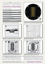
CROSSOVER NETWORK TUNING 3<br />
<strong>COIL</strong>S 5<br />
AIR CORED <strong>COIL</strong>S 5<br />
L71....................................................................................................................................... 6<br />
L100..................................................................................................................................... 6<br />
L140..................................................................................................................................... 7<br />
L200..................................................................................................................................... 7<br />
L250..................................................................................................................................... 8<br />
L300..................................................................................................................................... 8<br />
Air cored coils with baked varnish windings 9<br />
BL71 ................................................................................................................................. 9<br />
BL100 ............................................................................................................................. 10<br />
BL140 ............................................................................................................................. 10<br />
COPPER FOIL <strong>COIL</strong>S 11<br />
CFC16 ............................................................................................................................... 12<br />
CFC14 ............................................................................................................................... 12<br />
CFC12 ............................................................................................................................... 13<br />
CFC10 ............................................................................................................................... 13<br />
ARONIT 14<br />
E45..................................................................................................................................... 15<br />
E59..................................................................................................................................... 15<br />
E71..................................................................................................................................... 16<br />
ARONIT Coil with Baked Varnish Windings 17<br />
BE45............................................................................................................................... 18<br />
BE59............................................................................................................................... 18<br />
BE71............................................................................................................................... 18<br />
FERRITE <strong>COIL</strong>S 19<br />
F71..................................................................................................................................... 19<br />
F100................................................................................................................................... 19<br />
Ferrit coils with baked varnish windings 20<br />
BF71............................................................................................................................... 20<br />
BF100............................................................................................................................. 20<br />
FERRITE DRUM CORE <strong>COIL</strong>S 21<br />
HPGR 40............................................................................................................................ 21<br />
HPGR 56............................................................................................................................ 21<br />
Ferrite drum core coils with baked varnish windings 22<br />
BHPGR 40...................................................................................................................... 22<br />
BHPGR 56...................................................................................................................... 23<br />
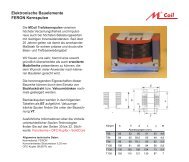
TRANSFORMER CORE <strong>COIL</strong>S WITH FERON 24<br />
T84..................................................................................................................................... 25<br />
T96..................................................................................................................................... 25<br />
T106................................................................................................................................... 25<br />
T130................................................................................................................................... 26<br />
T150................................................................................................................................... 26<br />
<strong>ZERO</strong> <strong>OHM</strong> <strong>COIL</strong> 27<br />
N106................................................................................................................................... 28<br />
N130................................................................................................................................... 28<br />
N150................................................................................................................................... 28<br />
VACUUM IMPREGNATION & BAKED VARNISH <strong>COIL</strong>S 29<br />
CAPACITORS .......................................................................................................................30<br />
MCAP-SUPREME 30<br />
SUP8.................................................................................................................................. 31
CAPZN 32<br />
250 VDC ............................................................................................................................ 32<br />
100 VDC ............................................................................................................................ 33<br />
630 VDC ............................................................................................................................ 33<br />
MCAP 34<br />
400 VDC (330µ=250VDC!)............................................................................................ 34<br />
630 VDC ............................................................................................................................ 35<br />
MKT FILM CAPACITORS 36<br />
250 VDC ............................................................................................................................ 36<br />
BIPOLAR ELECTROLYTIC CAPACITORS 37<br />
BG50.................................................................................................................................. 37<br />
BG35.................................................................................................................................. 38<br />
BR100................................................................................................................................ 38<br />
BR63.................................................................................................................................. 38<br />
HIGH LOAD RESISTORS...................................................................................................39<br />
CERAMIC RESISTORS 39<br />
R5...................................................................................................................................... 39<br />
R11 .................................................................................................................................... 39<br />
R17 .................................................................................................................................... 39<br />
METAL OXIDE FILM RESISTORS MR4 & MR 10 40<br />
mr4..................................................................................................................................... 40<br />
mr10................................................................................................................................... 40<br />
TERMINALS AND COPPER BINDIND POSTS..............................................................41<br />
2
Crossover Network Tuning<br />
Our experience shows that high-quality crossover network components can get between 30% and 50%<br />
more performance out of your speakers! Good crossovers don't cost all that much and they deliver radical<br />
improvements, even in low-cost configurations. This was graphically demonstrated in a report in the<br />
leading German hi-fi mag Klang & Ton (see quote below). In the "cheap trick" described in the K&T<br />
article (154€ for the speaker pair) the great enhancement in listening pleasure provided by using highend<br />
crossover components easily justified the additional cost of 77€, which is just one third of the<br />
total final cost of the speakers. It would be difficult to find a better illustration of the crucial importance<br />
and huge benefits of high-grade crossover components:<br />
("The replacement...brought a really striking improvement in quality, particularly in mid range, high<br />
range and overall presence. The new sound is completely natural, without any trace of 'loudspeaker'.<br />
It's as though there were no more speakers you could identify as the source of the sound - what you<br />
hear appears impressively disconnected from the physical speakers. Everyone who listened to the<br />
results agreed that the enhancement to the sound fully justified the additional DM150 for two highend<br />
crossovers.")<br />
("In the high-end version the second capacitor in the crossover is a MKP metallised paper model<br />
(C1, in parallel to the woofer). This component delivers a very perceptible improvement in the mid<br />
range over the inexpensive electrolytic capacitor, demonstrating that even the parallel components in<br />
a crossover have a real and significant influence on the sound.") Klang & Ton 4/98, p. 64 ff.<br />
Having read this you're probably interested in the details of "our" recipe for tuning a crossover network for<br />
optimum sound performance<br />
• Air is by far the best coil core material. Use air coils wherever possible. But remember, when<br />
you replace coils the new air coils must have the same low resistance (W rating) as the existing<br />
(cored) coils. This is crucial!<br />
• There's no alternative to coils with cores for applications calling for very high inductance values.<br />
When you have no choice, coils with Aronit cores are definitely preferable to ferrite, provided<br />
that their internal resistance is low enough.<br />
• On the other hand, ferrite core coils are easier to install in cars than coils with Aronit cores.<br />
• In the deep bass range there is ultimately no real alternative to transformer core coils and zero<br />
resistance coils. They are the only designs that enable you to combine extremely high<br />
inductance values with low resistance and exceptional power handling capacity.<br />
• However, reducing the internal resistance of the bass coil is not always advisable as this also<br />
changes the tuning of the system. As a basic rule of thumb you should only make this change if<br />
you want to change the bass tuning, making the basses more "dry and precise". It's important to<br />
understand that "dry" in this context also means "less" bass!<br />
• All coils, including the coils wired in parallel to the speaker unit, should have baked varnish<br />
windings (or vacuum impregnated windings with wire over 1.4mm thick).<br />
• Install an MCAP Supreme directly upstream from the tweeter. This generally makes the sound<br />
enormously more spatial and transparent.<br />
• When very high capacitance is called for, for example in two-way configurations with a low<br />
crossover frequency, you can save money by connecting an MCAP Supreme and an MCAP in<br />
parallel. (The Supreme should contribute at least 30% to the total rating.)<br />
• Mid-range: Connect an MCAP in series to the speaker unit.<br />
• If possible, all parallel capacitors should be MCAPs, or at least MKT metallised plastic film<br />
capacitors.<br />
• At a pinch you can also use film capacitors and electrolytic capacitors connected in parallel for<br />
the bass range.<br />
• All resistors in the signal path and parallel to the tweeter should be metal oxide components.<br />
3
• Install the crossover in its own separate housing or cast it in resin.<br />
Send us your circuit diagram or your original crossover network. We'll be happy to send you a quotation.<br />
If you want we can also install your high-end crossover for you!<br />
Whichever solution you choose, we're sure that you'll be delighted with the results of your Mundorf tuning<br />
project!<br />
4
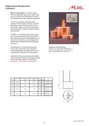
AIR CORED <strong>COIL</strong>S<br />
<strong>COIL</strong>S<br />
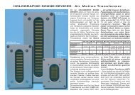
Air cored coils are, for physical reasons, unbeatable as far as accurate pulse reproduction<br />
and freedom from distortion are concerned. For this reason, for all the purists, we stock air<br />
cored coils with wire diameters of up to 3.0 mm. It is also possible in this way to create<br />
greater inductances with relatively low internal resistance. Vacuum impregnation, which is<br />
described in detail at the end of the chapter "Zero Ohm Coils", also leads in the air cored coils<br />
described here to greater detail and spatial quality in the reproduction of music.<br />
e2<br />
e1<br />
Round coil form<br />
Technical Specifications:<br />
Tolerance: Max 3%, typically 1.5%<br />
Electrolyte copper 99.99 % pure<br />
Coil forms: PA, glass fibre reinforced<br />
d<br />
l<br />
d1<br />
Körper 96, 106, 130, 150<br />
round coil form d l d1 e1 e2<br />
mm mm mm mm mm<br />
30/17 30 20 5.2 3 9<br />
36/8 36 10 5.2 5 12<br />
40/17 40 20 5.2 5 12<br />
58/15 58 18 5.2 6 20<br />
58/18 58 21.7 5.2 10 20<br />
58/25 58 27.7 5.2 10 20<br />
70/25 70 29 5.2 10 22.5<br />
K1 25 10.2 5 4 6.5<br />
K2 36 10.2 5 7 12<br />
K3 42 13.6 5 6 13.5<br />
K4 47 17.8 5 4 14.5<br />
K5 58 17.8 5 6 20<br />
K6 70 29 5 8 22.5<br />
K7 77 27.8 5 6 26<br />
square coil<br />
form<br />
A B H<br />
mm mm mm<br />
96 70 62 54<br />
106 88 75 61<br />
130 105 92 81<br />
150 107 97 83<br />
A<br />
H<br />
B<br />
5
Air cored coils with wire diameter 0,71 mm L71<br />
mH <strong>OHM</strong> KÖRPER €/Stk<br />
0,10 0,26 36/8<br />
0,12 0,28 36/8<br />
0,15 0,32 36/8<br />
0,18 0,34 36/8<br />
0,22 0,38 36/8<br />
0,27 0,45 36/8<br />
0,33 0,51 36/8<br />
0,39 0,51 36/8<br />
0,47 0,57 30/17.5<br />
0,56 0,64 30/17.5<br />
0,68 0,79 40/17.5<br />
0,82 0,89 40/17.5<br />
1,00 1,02 40/17.5<br />
1,20 1,08 40/17.5<br />
1,50 0,96 58/15<br />
1,80 1,15 58/15<br />
2,20 1,34 58/15<br />
2,70 1,53 58/15<br />
3,30 1,79 58/15<br />
3,90 2,04 58/15<br />
4,70 2,39 58/15<br />
5,60 2,77 58/15<br />
6,80 3,28 58/15<br />
8,20 3,30 58/25<br />
10,00 3,85 58/25<br />
12,00 4,47 70/25<br />
15,00 5,04 70/25<br />
22,00 5,61 70/25<br />
Air cored coils with wire diameter 1,00 mm L100<br />
mH <strong>OHM</strong> KÖRPER €/Stk<br />
0,10 0,11 30/17.5<br />
0,12 0,13 30/17.5<br />
0,15 0,16 30/17.5<br />
0,18 0,19 30/17.5<br />
0,22 0,23 40/17.5<br />
0,27 0,23 40/17.5<br />
0,33 0,26 40/17.5<br />
0,39 0,29 40/17.5<br />
0,47 0,32 40/17.5<br />
0,56 0,36 40/17.5<br />
0,68 0,45 58/15<br />
0,82 0,45 58/15<br />
1,00 0,49 58/15<br />
1,20 0,55 58/15<br />
1,50 0,65 58/15<br />
1,80 0,73 58/15<br />
2,20 0,84 58/25<br />
2,70 0,94 58/25<br />
3,30 1,10 58/25<br />
3,90 1,20 58/25<br />
4,70 1,26 70/25<br />
5,60 1,39 70/25<br />
6,80 1,56 70/25<br />
8,20 1,72 70/25<br />
6
Air cored coils with wire diameter 2,00 mm L140<br />
mH <strong>OHM</strong> KÖRPER €/Stk<br />
0,10 0,09 40/17.5<br />
0,12 0,09 40/17.5<br />
0,15 0,10 40/17.5<br />
0,18 0,11 58/15<br />
0,22 0,14 58/15<br />
0,27 0,15 58/15<br />
0,33 0,16 58/15<br />
0,39 0,18 58/15<br />
0,47 0,19 58/15<br />
0,56 0,25 58/18<br />
0,68 0,26 58/25<br />
0,82 0,28 58/25<br />
1,00 0,30 58/25<br />
1,20 0,33 70/25<br />
1,50 0,36 70/25<br />
1,80 0,43 70/25<br />
2,20 0,46 70/25<br />
2,70 0,60 K7<br />
3,30 0,66 K7<br />
3,90 0,00 K7<br />
4,70 0,80 106<br />
5,60 0,89 106<br />
6,80 1,07 106<br />
8,20 1,11 106<br />
10,00 1,24 106<br />
12,00 1,37 106<br />
Air cored coils with wire diameter 2,00 mm L200<br />
mH <strong>OHM</strong> KÖRPER €/Stk<br />
0,10 0,04 58/18<br />
0,12 0,05 58/18<br />
0,15 0,05 58/18<br />
0,18 0,06 58/25<br />
0,22 0,07 58/25<br />
0,27 0,07 58/25<br />
0,33 0,09 70/25<br />
0,39 0,10 70/25<br />
0,47 0,11 70/25<br />
0,56 0,12 70/25<br />
0,68 0,13 106<br />
0,82 0,15 106<br />
1,00 0,17 106<br />
1,20 0,21 106<br />
1,50 0,22 106<br />
1,80 0,24 106<br />
2,20 0,27 106<br />
2,70 0,30 130<br />
3,30 0,36 130<br />
3,90 0,41 130<br />
4,70 0,45 130<br />
5,60 0,49 130<br />
5,80 0,50 130<br />
6,80 0,55 130<br />
8,20 0,61 150<br />
10,00 0,68 150<br />
7
Air cored coils with wire diameter 2,50 mm L250<br />
mH <strong>OHM</strong> KÖRPER €/Stk<br />
0,22 0,05 106<br />
0,27 0,05 106<br />
0,33 0,06 106<br />
0,39 0,07 106<br />
0,47 0,08 106<br />
0,56 0,08 106<br />
0,68 0,10 106<br />
0,82 0,10 106<br />
1,00 0,12 106<br />
1,20 0,13 106<br />
1,50 0,17 130<br />
1,80 0,19 130<br />
2,20 0,21 130<br />
2,70 0,23 130<br />
3,30 0,25 130<br />
3,90 0,27 130<br />
4,70 0,31 150<br />
10,00 0,46 150<br />
12,00 0,58 150<br />
Air cored coils with wire diameter 3,00 mm L300<br />
mH <strong>OHM</strong> KÖRPER €/Stk<br />
0,15 0,03 106<br />
0,27 0,04 106<br />
0,33 0,05 106<br />
0,39 0,06 106<br />
0,47 0,06 106<br />
0,56 0,07 130<br />
0,68 0,07 130<br />
0,82 0,09 130<br />
1,00 0,10 130<br />
1,20 0,11 130<br />
1,50 0,12 130<br />
1,80 0,13 150<br />
2,20 0,15 150<br />
2,70 0,17 150<br />
3,30 0,19 150<br />
3,90 0,20 150<br />
4,70 0,22 170<br />
8,20 0,32 170<br />
10,00 0,38 195<br />
12,00 0,46 195<br />
8
Air cored coils with baked varnish windings<br />
Air cored coils are, for physical reasons, unbeatable as far as accurate pulse reproduction<br />
and freedom from distortion are concerned The windings of baked varnish coils are made<br />
using a special wire. After the coil has been wound it is heated up causing an additional layer<br />
of varnish on the wire to melt, bonding the individual windings firmly together. The effect is<br />
similar to that achieved with vacuum impregnation, but this process is cheaper for small<br />
coils. Baked varnish coils are available with winding diameters from 0.71mm – 1.40mm. All<br />
series are identified with a “b” prefix.<br />
Technical Specifications:<br />
Tolerance: Max 3%, typically 1.5%<br />
Electrolyte copper 99.99 % pure<br />
Coil forms: PA, glass fibre reinforced<br />
round coil form d l d1 e1 e2<br />
mm mm mm mm mm<br />
30/17 30 20 5.2 3 9<br />
36/8 36 10 5.2 5 12<br />
40/17 40 20 5.2 5 12<br />
58/15 58 18 5.2 6 20<br />
58/18 58 21.7 5.2 10 20<br />
58/25 58 27.7 5.2 10 20<br />
70/25 70 29 5.2 10 22.5<br />
K7 77 27.8 5 6 26<br />
Air cored coils with backed varnish wire 0.71 mm BL71<br />
mH <strong>OHM</strong> KÖRPER €/Stk<br />
0,10 0,26 36/8<br />
0,12 0,28 36/8<br />
0,15 0,32 36/8<br />
0,18 0,34 36/8<br />
0,22 0,38 36/8<br />
0,27 0,45 36/8<br />
0,33 0,51 36/8<br />
0,39 0,51 36/8<br />
0,47 0,57 30/17.5<br />
0,56 0,64 30/17.5<br />
0,68 0,79 40/17.5<br />
0,82 0,89 40/17.5<br />
1,00 1,02 40/17.5<br />
1,20 1,08 40/17.5<br />
1,50 0,96 58/15<br />
1,80 1,15 58/15<br />
2,20 1,34 58/15<br />
2,70 1,53 58/15<br />
3,30 1,79 58/15<br />
3,90 2,08 58/15<br />
4,70 2,39 58/15<br />
5,60 2,77 58/15<br />
6,80 3,28 58/15<br />
8,20 3,30 58/25<br />
10,00 3,85 58/25<br />
15,00 5,04 70/25<br />
22,00 5,61 70/25<br />
27,00 6,44 70/25<br />
e2<br />
e1<br />
d<br />
l<br />
d1<br />
9
Air cored coils with backed varnish wire 1.00 mm BL100<br />
mH <strong>OHM</strong> KÖRPER €/Stk<br />
0,10 0,23 30/17.5<br />
0,12 0,16 30/17.5<br />
0,15 0,16 30/17.5<br />
0,18 0,19 30/17.5<br />
0,22 0,23 40/17.5<br />
0,27 0,23 40/17.5<br />
0,33 0,26 40/17.5<br />
0,39 0,29 40/17.5<br />
0,47 0,32 40/17.5<br />
0,56 0,36 40/17.5<br />
0,68 0,45 58/15<br />
0,82 0,45 58/15<br />
1,00 0,49 58/15<br />
1,20 0,55 58/15<br />
1,50 0,65 58/15<br />
1,80 0,73 58/15<br />
2,20 0,84 58/25<br />
2,70 0,95 58/25<br />
3,30 1,10 58/25<br />
3,90 1,20 58/25<br />
4,70 1,26 70/25<br />
5,60 1,39 70/25<br />
6,80 1,51 70/25<br />
8,20 1,56 70/25<br />
Air cored coils with backed varnish wire 1.40 mm BL140<br />
mH <strong>OHM</strong> KÖRPER €/Stk<br />
0,10 0,09 40/17.5<br />
0,12 0,09 40/17.5<br />
0,15 0,10 40/17.5<br />
0,18 0,11 58/15<br />
0,22 0,14 58/15<br />
0,27 0,15 58/15<br />
0,33 0,16 58/15<br />
0,39 0,18 58/15<br />
0,47 0,19 58/15<br />
0,56 0,23 58/18<br />
0,68 0,26 58/25<br />
0,82 0,28 58/25<br />
1,00 0,30 58/25<br />
1,20 0,33 70/25<br />
1,50 0,36 70/25<br />
1,80 0,43 70/25<br />
2,20 0,54 70/25<br />
2,70 0,60 K7<br />
3,30 0,66 K7<br />
3,90 0,67 K7<br />
4,70 0,88 106<br />
10
COPPER FOIL <strong>COIL</strong>S<br />
For some time we have been succesfully offering copper foil coils manufactured dy us of the<br />
oxygen-free copper(OFC).<br />
OFC is charecterised by ist special purity and the structure of the crystal lattice.<br />
The electrical advantages of the design add themselves to the excellent sound characteristics<br />
of this noble material. A winding is wound on a winding( not in layers at each other as in the<br />
conventional coils),that`s why this design comes much closer to the physically ideal coil. This<br />
expresses itself e.g. by the item that the coil stays constant till more than 100 kHz.Besides,<br />
the undesirable capasitive part of the coil is especially small, so that even very high<br />
frequencies (VHF) can be effectively blocked.<br />
Technical Data:<br />
Tolerance: max 2.5%, typical 1.5%<br />
Copper- Foil: 70µ<br />
Five-Nines-OFC-Kupfer 99.999 % rein<br />
Isolation: Polypropylen 20µ<br />
Inner Diameter: 12 mm<br />
Highness (h):<br />
cfc16: 17 mm<br />
cfc14: 27 mm<br />
cfc12: 44 mm<br />
cfc10: 70 mm<br />
Additional we even offer mounting sets:<br />
Baureihe Spulen Befestigun<br />
gssatz<br />
€/Stk<br />
cfc16 poly16 1,20<br />
cfc14 poly14 1,29<br />
cfc12 poly12 1,48<br />
cfc10 poly10 2,73<br />
D<br />
h<br />
11
CFC16<br />
Diameter:17*0.075 mm=1.275 qmm Aquivalent round wire:1.28 mm<br />
Highness: 27 mm<br />
mH <strong>OHM</strong> Ø €/Stk<br />
0,10 0,10 36<br />
0,12 0,10 36<br />
0,15 0,11 36<br />
0,18 0,12 36<br />
0,22 0,13 38<br />
0,27 0,16 42<br />
0,33 0,18 44<br />
0,39 0,20 46<br />
0,47 0,22 48<br />
0,56 0,24 50<br />
0,68 0,26 52<br />
0,82 0,29 54<br />
1,00 0,33 57<br />
1,20 0,38 61<br />
1,50 0,43 65<br />
1,80 0,50 70<br />
2,20 0,54 72<br />
2,70 0,61 77<br />
3,30 0,69 81<br />
3,90 0,75 85<br />
4,70 0,86 91<br />
5,60 0,95 95<br />
6,80 1,10 102<br />
CFC14<br />
Diameter: 28*0.075 qmm=2.1 qmm Aquivalent round wire:1.63 mm<br />
Highness: 38 mm<br />
mH <strong>OHM</strong> Ø €/Stk<br />
0,10 0,06 40<br />
0,12 0,07 40<br />
0,15 0,08 40<br />
0,18 0,09 40<br />
0,22 0,09 42<br />
0,27 0,11 46<br />
0,33 0,13 49<br />
0,39 0,14 51<br />
0,47 0,15 52<br />
0,56 0,16 54<br />
0,68 0,20 60<br />
0,82 0,22 63<br />
1,00 0,23 64<br />
1,20 0,26 68<br />
1,50 0,30 70<br />
1,80 0,32 71<br />
2,20 0,35 78<br />
2,70 0,43 78<br />
2,90 0,47 86<br />
3,30 0,50 93<br />
3,90 0,53 95<br />
4,70 0,59 100<br />
5,60 0,65 105<br />
6,80 0,74 112<br />
8,20 0,82 118<br />
12,00 1,19 135<br />
12
CFC12<br />
mH<br />
Diameter: 44*0.075 mm=3.3 qmm<br />
Aquivalent round wire: 2 mm<br />
Highness: 54 mm<br />
<strong>OHM</strong> Ø €/Stk<br />
0,10 0,06 46<br />
0,12 0,06 46<br />
0,15 0,07 46<br />
0,18 0,08 46<br />
0,22 0,08 49<br />
0,27 0,08 49<br />
0,33 0,09 52<br />
0,39 0,10 54<br />
0,47 0,11 56<br />
0,56 0,12 59<br />
0,68 0,13 61<br />
0,82 0,15 65<br />
1,00 0,17 69<br />
1,20 0,19 73<br />
1,50 0,21 76<br />
1,80 0,24 81<br />
2,20 0,27 86<br />
2,70 0,31 92<br />
3,30 0,35 98<br />
3,90 0,39 103<br />
4,70 0,43 108<br />
5,60 0,47 113<br />
6,80 0,52 118<br />
8,20 0,56 125<br />
10,00 0,85 140<br />
12,00 0,85 140<br />
CFC10<br />
mH<br />
Diameter: 70*0.075 mm=6 qmm<br />
Aquivalent round wire: 2.76 mm<br />
Highness: 80 mm<br />
<strong>OHM</strong> Ø €/Stk<br />
0,22 0,06 51<br />
0,25 0,06 52<br />
0,27 0,07 52<br />
0,33 0,07 54<br />
0,47 0,08 57<br />
0,56 0,10 62<br />
0,68 0,11 67<br />
0,82 0,13 71<br />
1,00 0,14 74<br />
1,20 0,15 77<br />
1,50 0,16 80<br />
1,80 0,18 83<br />
2,20 0,20 88<br />
2,70 0,23 92<br />
3,30 0,25 99<br />
3,90 0,28 104<br />
4,70 0,31 109<br />
5,60 0,34 114<br />
6,80 0,38 121<br />
13
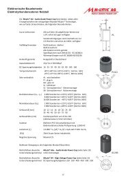
ARONIT Coil with Baked Varnish Windings<br />
Aronit is a sintered metal material that is highly resistant to distortion even under very<br />
extreme stresses. Together with specially designed bobbins this material makes it possible to<br />
produce coils with extremely low resistance and excellent value for money. Aronit coils<br />
are the ideal choice for all applications calling for high power and low distortion at a<br />
reasonable cost.<br />
The windings of baked varnish coils are made using a special wire. After the coil has been<br />
wound it is heated up causing an additional layer of varnish on the wire to melt, bonding the<br />
individual windings firmly together. The effect is similar to that achieved with vacuum<br />
impregnation, but this process is cheaper for small coils. Baked varnish coils are available<br />
with winding diameters from 0.71mm – 1.40mm. All series are identified with a “b” prefix (see<br />
p. 23).<br />
e71, e77<br />
e45, e59<br />
Specifications:<br />
Tolerance: 3%<br />
e2<br />
e1<br />
e2<br />
e1<br />
Core material: ARONIT<br />
Four Nines OFC copper 99.998% pure<br />
Bobbin material: Fibreglass-reinforced PA<br />
l<br />
Series d l e1 e2<br />
mm mm mm mm<br />
e45 45 29.5 7 11<br />
e59 70 59 10 22.5<br />
e71 70 29 10 22.5<br />
l<br />
d<br />
d<br />
17
FERRITE <strong>COIL</strong>S<br />
Ferrite coils, of which we have only a limited range at the moment, supplement the<br />
programme for applications in parallel circuits, series resonant circuits, etc. where low<br />
internal resistance is less important than small dimensions and low costs.<br />
e2<br />
e1<br />
Technical Specifications:<br />
coil form<br />
d<br />
l<br />
d1<br />
D<br />
Tolerance: Max 3%, typically 1.5%<br />
Electrolyte copper 99.99 % pure<br />
Coil forms: PA, glass fibre reinforced<br />
l d1 e1 e2<br />
mm mm mm mm mm<br />
30/17 30 20 5.2 3 9<br />
40/17 40 20 5.2 5 12<br />
Ferrite coils with 0,71mm wire diameter F71<br />
mH <strong>OHM</strong> KÖRPER €/Stk<br />
1,00 0,36 30/17.5<br />
1,20 0,45 30/17.5<br />
1,50 0,61 30/17.5<br />
1,80 0,79 40/17.5<br />
2,20 0,91 40/17.5<br />
2,70 1,01 40/17.5<br />
3,00 1,06 40/17.5<br />
3,30 1,12 40/17.5<br />
3,90 1,22 40/17.5<br />
4,70 1,52 40/17.5<br />
Ferrite coils with 1,00 mm wire diameter F100<br />
mH <strong>OHM</strong> KÖRPER €/Stk<br />
0,47 0,20 30/17.5<br />
0,56 0,23 40/17.5<br />
0,68 0,26 40/17.5<br />
0,82 0,30 40/17.5<br />
1,00 0,34 40/17.5<br />
1,20 0,40 40/17.5<br />
19
Ferrit coils with baked varnish windings<br />
Ferrite coils, of which we have only a limited range at the moment, supplement the<br />
programme for applications in parallel circuits, series resonant circuits, etc. where low<br />
internal resistance is less important than small dimensions and low costs.<br />
The windings of baked varnish coils are made using a special wire. After the coil has been<br />
wound it is heated up causing an additional layer of varnish on the wire to melt, bonding the<br />
individual windings firmly together. The effect is similar to that achieved with vacuum<br />
impregnation, but this process is cheaper for small coils. Baked varnish coils are available<br />
with winding diameters from 0.71mm – 1.40mm. All series are identified with a “b” prefix.<br />
e2<br />
e1<br />
d<br />
l<br />
d1<br />
Technical Specifications:<br />
Tolerance: Max 3%, typically 1.5%<br />
Electrolyte copper 99.99 % pure<br />
Coil forms: PA, glass fibre reinforced<br />
coil form d l d1 e1 e2<br />
mm mm mm mm mm<br />
30/17 30 20 5.2 3 9<br />
40/17 40 20 5.2 5 12<br />
Ferrite coils with backed varnish wire 0.71 mm BF71<br />
mH <strong>OHM</strong> KÖRPER €/Stk<br />
1,00 0,36 30/17.5<br />
1,49 1,44 30/17.5<br />
1,50 0,61 30/17.5<br />
1,80 0,79 40/17.5<br />
2,20 0,91 40/17.5<br />
2,70 1,01 40/17.5<br />
3,00 1,06 40/17.5<br />
3,30 1,12 40/17.5<br />
3,90 1,22 40/17.5<br />
Ferrite coils with backed varnish wire 1.00 mm BF100<br />
mH <strong>OHM</strong> KÖRPER €/Stk<br />
0,47 0,20 30/17.5<br />
0,56 0,23 40/17.5<br />
0,68 0,26 40/17.5<br />
0,82 0,30 40/17.5<br />
1,00 0,34 40/17.5<br />
1,20 0,40 40/17.5<br />
20
38<br />
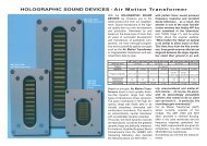
FERRITE DRUM CORE <strong>COIL</strong>S<br />
Our high-performance HP 3616 ferrite is the answer for many users’ need for an inexpensive,<br />
high-power ferrite material. The mechanical advantages of these relatively small coils are<br />
obvious, but it wasn’t until this new HP 3616 material became available that we could even<br />
consider adding a ferrite core to our product line. This German-made ferrite offers a<br />
significantly higher performance than the cheap Asian cores used in many other products.<br />
The HP series combines excellent electrical and mechanical specifications with<br />
relatively low unit costs.<br />
40<br />
hpgr40<br />
4.8<br />
56<br />
hpgr56<br />
35<br />
5.0<br />
Specifications:<br />
Core material: HP 3616<br />
Tolerance: Max. 3%<br />
Electrolyte copper 99.99% pure<br />
Dimensions:<br />
HPGR 40: 40x38mm (DxH)<br />
Centre hole: 5.00mm<br />
HPGR 56: 56x35mm (DxH)<br />
Centre hole: 4.2mm<br />
FERRIT DRUM CORE <strong>COIL</strong>S 40 mm Ø HPGR 40<br />
mH <strong>OHM</strong> DRAHT €/Stk<br />
1,00 0,15 1,00<br />
1,20 0,15 1,00<br />
1,50 0,16 1,00<br />
1,80 0,18 1,00<br />
2,20 0,21 1,00<br />
2,70 0,27 1,00<br />
3,30 0,28 1,00<br />
4,70 0,35 1,00<br />
5,60 0,64 0,71<br />
6,80 0,68 0,71<br />
8,20 0,92 0,71<br />
10,00 1,00 0,71<br />
12,00 1,20 0,71<br />
15,00 1,54 0,71<br />
27,00 2,72 0,71<br />
FERRIT DRUM CORE <strong>COIL</strong>S 56 mm Ø HPGR 56<br />
mH <strong>OHM</strong> DRAHT €/Stk<br />
1,00 0,12 1,40<br />
1,50 0,14 1,40<br />
1,80 0,14 1,40<br />
2,70 0,17 1,40<br />
3,30 0,21 1,40<br />
3,90 0,22 1,40<br />
4,70 0,24 1,32<br />
6,80 0,58 0,00<br />
8,20 0,65 0,00<br />
10,00 0,70 1,00<br />
12,00 0,73 1,00<br />
15,00 0,82 1,00<br />
21
Ferrite drum core coils with baked varnish windings<br />
Our high-performance HP 3616 ferrite is discribed the side before. The windings of baked<br />
varnish coils are made using a special wire. After the coil has been wound it is heated up<br />
causing an additional layer of varnish on the wire to melt, bonding the individual windings<br />
firmly together. The effect is similar to that achieved with vacuum impregnation, but this<br />
process is cheaper for small coils. Baked varnish coils are available with winding diameters<br />
from 0.71mm – 1.40mm. All series are identified with a “b” prefix.<br />
3 8<br />
40<br />
hpgr40<br />
4.8<br />
56<br />
hpgr56<br />
5.0<br />
3 5<br />
FERRIT DRUM <strong>COIL</strong>S 40 mm Ø WITH BACKED VARNISH<br />
WIRE<br />
Specifications:<br />
Core material: HP 3616<br />
Tolerance: Max. 3%<br />
Electrolyte copper 99.99% pure<br />
Dimensions:<br />
HPGR 40: 40x38mm (DxH)<br />
Centre hole: 5.00mm<br />
HPGR 56: 56x35mm (DxH)<br />
Centre hole: 4.2mm<br />
BHPGR 40<br />
mH <strong>OHM</strong> DRAHT €/Stk<br />
1,00 0,13 1,00<br />
1,20 0,15 1,00<br />
1,50 0,16 1,00<br />
1,80 0,18 1,00<br />
2,20 0,21 1,00<br />
2,70 0,24 1,00<br />
3,30 0,28 1,00<br />
3,90 0,31 1,00<br />
4,70 0,64 0,71<br />
5,60 0,65 0,71<br />
6,80 0,79 0,71<br />
10,00 0,96 0,71<br />
12,00 1,20 0,71<br />
15,00 1,20 0,71<br />
33,00 2,02 0,71<br />
22
FERRIT CORE <strong>COIL</strong>S 56 mm Ø WITH BACKED VARNISH<br />
WIRE<br />
BHPGR 56<br />
mH <strong>OHM</strong> DRAHT €/Stk<br />
1,00 0,10 1,40<br />
1,20 0,12 1,40<br />
1,50 0,14 1,40<br />
1,80 0,14 1,40<br />
2,00 0,15 0,00<br />
2,70 0,17 1,40<br />
3,00 0,19 1,40<br />
3,30 0,21 1,40<br />
3,60 0,21 1,40<br />
4,00 0,24 1,32<br />
4,70 0,29 1,32<br />
5,60 0,31 1,32<br />
6,80 0,49 1,12<br />
8,20 0,58 1,12<br />
10,00 0,65 1,00<br />
12,00 0,73 1,00<br />
15,00 0,82 1,00<br />
23
Transformer core coils with Core 84 T84<br />
mH <strong>OHM</strong> DRAHT €/Stk<br />
1,00 0,07 1,80<br />
1,20 0,07 1,80<br />
1,50 0,07 1,80<br />
1,80 0,09 1,80<br />
2,20 0,12 1,40<br />
2,70 0,17 1,40<br />
3,30 0,24 1,32<br />
3,90 0,26 1,32<br />
4,70 0,29 1,32<br />
5,60 0,31 1,32<br />
6,80 0,36 1,25<br />
8,20 0,40 1,25<br />
10,00 0,75 1,00<br />
12,00 0,81 1,00<br />
15,00 0,91 1,00<br />
Transformer core coils with Core 96 T96<br />
mH <strong>OHM</strong> DRAHT €/Stk<br />
1,50 0,08 2,00<br />
1,80 0,09 2,00<br />
2,20 0,10 2,00<br />
2,70 0,10 2,00<br />
3,30 0,15 1,80<br />
3,90 0,16 1,80<br />
4,70 0,18 1,80<br />
5,60 0,24 1,60<br />
6,80 0,27 1,60<br />
8,20 0,29 1,60<br />
10,00 0,39 1,40<br />
15,00 0,57 1,32<br />
18,00 0,63 1,32<br />
22,00 0,76 1,25<br />
30,00 1,14 1,12<br />
Transformer core coils with Core 106 T106<br />
mH <strong>OHM</strong> DRAHT €/Stk<br />
1,50 0,04 3,00<br />
1,80 0,04 3,00<br />
2,20 0,07 2,50<br />
2,70 0,08 2,50<br />
3,30 0,09 2,50<br />
3,90 0,10 2,50<br />
4,70 0,14 2,00<br />
5,60 0,15 2,00<br />
6,80 0,18 2,00<br />
8,20 0,20 2,00<br />
10,00 0,22 2,00<br />
12,00 0,31 1,80<br />
15,00 0,36 1,80<br />
18,00 0,47 1,60<br />
22,00 0,55 1,60<br />
30,00 0,71 1,50<br />
33,00 0,77 1,50<br />
38,00 0,85 1,40<br />
25
Transformer core coils with Core 130 T130<br />
mH <strong>OHM</strong> DRAHT €/Stk<br />
1,20 0,06 3,00<br />
1,50 0,06 3,00<br />
3,00 0,06 3,00<br />
3,30 0,06 3,00<br />
3,60 0,07 3,00<br />
3,90 0,07 3,00<br />
4,70 0,08 3,00<br />
5,60 0,09 3,00<br />
6,80 0,12 2,50<br />
8,20 0,15 2,50<br />
9,00 0,16 2,50<br />
10,00 0,17 2,50<br />
12,00 0,19 2,50<br />
15,00 0,28 2,00<br />
18,00 0,33 2,00<br />
22,00 0,37 2,00<br />
27,00 0,42 2,00<br />
33,00 0,48 2,00<br />
40,00 0,53 1,80<br />
42,00 0,56 1,80<br />
Transformer core coils with Core 150 T150<br />
mH <strong>OHM</strong> DRAHT €/Stk<br />
8,20 0,11 3,00<br />
8,50 0,11 3,00<br />
10,00 0,12 3,00<br />
12,00 0,13 3,00<br />
15,00 0,15 3,00<br />
18,00 0,23 2,50<br />
22,00 0,25 2,50<br />
25,00 0,29 2,50<br />
26
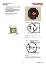
<strong>ZERO</strong> <strong>OHM</strong> <strong>COIL</strong><br />
The zero ohm coil (ZOC) is a special form of transformer core coil. This is also made of<br />
the top quality material FERON described in the chapter "Transformer Core Coils". In<br />
the ZOC, an air gap is calibrated and adjusted by hand between the two laminated<br />
cores (one I-shaped and one E-shaped). The air gap determines the inductivity of the<br />
coil and demands great care in the manufacturing process. It must not be too small, as<br />
saturation effects would otherwise occur at high loadings. The high production costs of<br />
the ZOC, and thus its higher price, are always justified when maximum faithfulness in<br />
pulse reproduction is required.<br />
E<br />
Luftspalt<br />
I<br />
Technical Specifications:<br />
Tolerance : Max. 5% , typically 3%<br />
core : FERON<br />
Elektrolyte copper 99,99% pure<br />
b<br />
CORE b h d x y e<br />
e<br />
d<br />
y<br />
mm mm mm mm mm mm<br />
n106 106 94 88 84 60 5.8<br />
n130 130 118 105 84 71 5.8<br />
n150 150 132 107 122.5 71 7<br />
h<br />
x<br />
27
Zero Ohm Coil, Core 106 N106<br />
mH <strong>OHM</strong> DRAHT €/Stk<br />
1,50 0,02 0,04<br />
1,80 0,02 0,04<br />
2,20 0,02 0,04<br />
2,70 0,02 0,04<br />
3,30 0,02 0,04<br />
3,90 0,05 3,00<br />
4,70 0,05 3,00<br />
5,60 0,05 3,00<br />
8,20 0,10 2,50<br />
8,50 0,10 2,50<br />
10,00 0,10 2,50<br />
12,00 0,24 2,00<br />
15,00 0,24 2,00<br />
18,00 0,24 2,00<br />
Zero Ohm Coil, Core 130 N130<br />
mH <strong>OHM</strong> DRAHT €/Stk<br />
3,30 0,03 0,04<br />
3,90 0,03 0,04<br />
4,70 0,03 0,04<br />
5,60 0,03 0,04<br />
6,80 0,03 0,04<br />
8,20 0,03 0,04<br />
10,00 0,10 3,00<br />
12,00 0,10 3,00<br />
15,00 0,10 3,00<br />
18,00 0,10 3,00<br />
22,00 0,21 2,50<br />
27,00 0,21 2,50<br />
30,00 0,21 2,50<br />
Zero Ohm Coil, Core 150 N150<br />
mH <strong>OHM</strong> DRAHT €/Stk<br />
10,00 0,05 0,04<br />
12,00 0,05 0,04<br />
15,00 0,05 0,04<br />
18,00 0,05 0,04<br />
22,00 0,06 0,04<br />
27,00 0,14 3,00<br />
33,00 0,14 3,00<br />
28
VACUUM IMPREGNATION & BAKED VARNISH <strong>COIL</strong>S<br />
In non-impregnated coils, vibration occurs as a result of the current flowing through the<br />
coil. The microphonic effect, i.e. the conversion of mechanical into electric oscillations,<br />
adds these oscillations back to the original signal as additional information. In this way,<br />
details of the original signal are overlaid and rendered unrecognisable. The music loses<br />
spatial quality and transparency. This process is prevented by vacuum impregnation.<br />
In vacuum impregnation, the coil is first impregnated with a special lacquer under<br />
vacuum. Because of the vacuum, this lacquer flows right into the innermost windings.<br />
The lacquer is subsequently dried in an oven at 130 øC. Thus the whole coil is baked into<br />
a very solid unit. The individual windings are prevented from vibrating and the original<br />
signal remains uncorrupted.<br />
Vacuum impregnation preserves musical details which give the music natural liveliness<br />
and an excellent spatial quality. It is thus an important component for a really audiophile<br />
reproduction of music.<br />
The price for vacuum impregnation is € 8.40 per coil.<br />
The windings of baked varnish coils are made using a special wire. After the coil has<br />
been wound it is heated up causing an additional layer of varnish on the wire to melt,<br />
bonding the individual windings firmly together. The effect is similar to that achieved with<br />
vacuum impregnation, but this process is cheaper for small coils. Baked varnish coils<br />
are available with winding diameters from 0.71mm – 1.40mm. All series are identified<br />
with a “b” prefix.<br />
29
MCAP-SUPREME<br />
CAPACITORS<br />
The M-CAP SUPREME has been internationally acclaimed as the ultimate high-end capacitor.<br />
Its outstanding sound performance is achieved with a unique combination of advanced<br />
technologies:<br />
• Special induction-free winding technology: Two capacitor windings are interleaved so<br />
that their inductances effectively cancel each other out. These two windings are connected<br />
in series. This means that it takes two 2µF windings to make a single 1µF M-CAP<br />
SUPREME capacitor – the same amount that it would take to produce a full 4µF of<br />
capacity using conventional technology!<br />
• Best available materials: The polypropylene film used for the M-CAP SUPREME has<br />
exceptionally low loss characteristics.<br />
• Sturdy plastic and aluminium cases: This prevents microphone effect feedback, thus<br />
protecting important signal details.<br />
• The resulting listening experience more than justifies all the effort we put into the<br />
M-CAP SUPREME. No other capacitor delivers a more spatial sound with such<br />
perfect reproduction of the finest musical nuances.<br />
No matter where you use the M-CAP SUPREME – as a coupling capacitor in your CD player<br />
or amplifier, or in the crossover of your speakers – you always get the same surprising and<br />
impressive performance. This capacitor mobilises such unbelievable reserves in your sound<br />
system that it is really justified to speak of a new dimension of music reproduction.<br />
Furthermore, the effect is not only achieved with very expensive high-end components. It<br />
delivers a significant enhancement in more price-conscious configurations, making it a very<br />
worthwhile upgrade. (Review: Klang & Ton 4/98, p. 68)<br />
D<br />
If you’re serious about high end, you need to try this capacitor!<br />
L<br />
Specifications:<br />
Dielectric: Polypropylene<br />
Dielectric strength: 1.200/800V DC<br />
Tolerance: ±2%, typ. 1%<br />
Loss angle tan δ: 0.00002 at 1kHz, 0.00001 at<br />
10kHz<br />
30
MCAP- Supreme MKP CAPACITOR 800 VDC SUP8<br />
µF VDC D*L/mm €/Stk<br />
0,10 1200 17*36<br />
0,15 1200 19*38<br />
0,22 1200 20*38<br />
0,33 1200 25*52<br />
0,47 800 20*39<br />
0,56 800 20*39<br />
0,68 800 20*39<br />
0,82 800 20*40<br />
1,00 800 20*40<br />
1,50 800 25*55<br />
1,80 800 25*55<br />
2,20 800 25*55<br />
2,70 800 30*56<br />
3,30 800 30*56<br />
3,90 800 30*56<br />
4,70 800 36*56<br />
5,60 800 36*56<br />
6,80 800 41*57<br />
8,20 800 36*106<br />
10,00 800 36*106<br />
15,00 800 41*102<br />
22,00 800 50*106<br />
31
CAPZN<br />
The M-CAP ZN is a tinfoil capacitor of the highest class. Solid tinfoil, together with high grade<br />
polypropylene as dielectric, are used in its manufacture. This massive tin layer improves the<br />
sound properties in unexpected ways:<br />
Because of the great weight of the tinfoil and the resulting mass inertia, oscillation of the foil<br />
and the accompanying microphonic effect are effectively prevented. Similarly to the vacuum<br />
impregnation which we provide for choke coils, this fact leads to an increase in transparency<br />
and spatial quality.<br />
The loss angle tan δ at 1 kHz is ten times smaller than that for a normal MKP* capacitor. It is<br />
only 0.00002 at 1 kHz and a mere 0.00001 at 10 kHz. This makes this capacitor incredibly<br />
quick and lively. Both of these mean a genuine innovation. The M-CAP ZN is a milestone on<br />
the road to perfect music reproduction!<br />
D<br />
L<br />
250 VDC<br />
Technical Specifications:<br />
Dielectric: Polypropylen<br />
Voltage Rating: 250 VDC<br />
Thickness of tinfoil, 7µm<br />
Tolerance: ± 2%, typ. 1%<br />
Loss factor tan δ:<br />
0.00002 bei 1kHz<br />
0.00001 bei 10 kHz<br />
TINFOIL CAPACITOR 250 VDC 2% MCAPZN<br />
µF VDC D*L/mm €/Stk<br />
0,10 250 9*23<br />
0,15 250 11*23<br />
0,22 250 10*30<br />
0,33 250 12*30<br />
0,47 250 14*30<br />
0,56 250 14.5*30<br />
0,68 250 16*35<br />
0,82 250 18*35<br />
1,00 250 18*39<br />
1,20 250 19*39<br />
1,50 250 21*39<br />
1,80 250 23*39<br />
2,20 250 25*39<br />
32
100 VDC<br />
TINFOIL CAPACITOR 100 VDC 2% MCAPZN<br />
µF VDC D*L/mm €/Stk<br />
2,70 100 20*39<br />
3,30 100 23.5*39<br />
3,90 100 24*41<br />
4,70 100 25*41<br />
630 VDC<br />
TINFOIL CAPACITOR 630 VDC 2% MCAPZN63<br />
µF VDC D*L/mm €/Stk<br />
0,10 630 11*25<br />
0,15 630 13*24<br />
0,22 630 13*28<br />
0,33 630 15*29<br />
0,47 630 16*38<br />
0,56 630 18*38<br />
0,68 630 19*38<br />
1,00 630 22*40<br />
1,50 630 26*40<br />
33
MCAP<br />
The M-CAP is an audiophile metallized polypropylene capacitor. In selection of the materials<br />
used, special attention was given to the sound properties. Great care taken during the<br />
production guarantees constant high quality and minimum electrical and mechanical<br />
tolerances. Thus, in the final inspection, maximum deviations in capacitance of 1.5 % are<br />
measured, so the guaranteed value of 3 % is far exceeded. The practically induction-free type<br />
of construction and the low loss factor of the M-CAP results in a very "quick" capacitor. The<br />
M-CAP forms the basis for vivid music reproduction rich in nuance.<br />
The 630 V DC version with capacitances in the range from 0.1 µF to 0.82 µF is equally<br />
suitable as a bypass capacitor in high quality frequency crossovers or as a coupling<br />
capacitance in valve and transistor amplifiers.<br />
400 VDC (330µ=250VDC!)<br />
D<br />
L<br />
Technical Specifications:<br />
Film: metallized polypropylene<br />
Voltage rating: 400-630 VDC<br />
Tolerance : max.3%, typically. 1.5%<br />
Loss factor: tan δ = 0.0002<br />
(for 1kHz/1μF)<br />
MKP-CAPACITOR 400 VDC 3% mcap<br />
µF VDC D*L/mm €/Stk<br />
0,1-0,82 Siehe mcap 630 VDC<br />
1,00 400 13*23<br />
1,50 400 14*23<br />
1,80 400 15*26<br />
2,20 400 16*26<br />
2,70 400 15*28<br />
3,30 400 17*34<br />
3,90 400 18*34<br />
4,70 400 20*34<br />
5,60 400 21*34<br />
6,80 400 23*34<br />
8,20 400 24*37<br />
10 400 26*37<br />
15 400 29*46<br />
22 400 35*46<br />
33 400 38*53<br />
47 400 43*59<br />
56 400 45*66<br />
68 400 47*66<br />
82 400 54*66<br />
100 400 56*72<br />
150 400 62*85<br />
220 400 63*115<br />
330 250 !!!!! 63*115<br />
34
630 VDC<br />
% MKP-CAPACITOR 630 VDC 3% mcap63<br />
µF VDC D*L/mm €/Stk<br />
0,10 630 10*19<br />
0,15 630 10*26<br />
0,22 630 11*26<br />
0,27 630 11*26<br />
0,33 630 11*26<br />
0,39 630 13*26<br />
0,47 630 13*26<br />
0,56 630 14*26<br />
0,68 630 14*26<br />
0,82 630 14*26<br />
1,00 630 16.1*25<br />
1,50 630 17.1*28<br />
2,20 630 18*33<br />
3,30 630 22*33<br />
3,90 630 22.9*38<br />
4,70 630 23.5*38<br />
5,60 630 25.6*38<br />
6,80 630 25.8*43<br />
8,20 630 28.3*43<br />
10,00 630 29*48<br />
35
MKT FILM CAPACITORS<br />
MKT capacitors are metallized polyesther flim capacitors. They range both in price and<br />
in quality between the low-loss M-CAP and the inexpensive bipolar electrolytic<br />
capacitors. The loss factor of an MKT capacitor is about 20 times that of an M-CAP, but<br />
less than a tenth of the loss factor of a bipolar electrolytic capacitor. (Loss factor M-<br />
CAP: 0.0002, MKT:
BIPOLAR ELECTROLYTIC CAPACITORS<br />
A distinction is made in bipolar electrolytic capacitors between two construction types,<br />
"rough" and "smooth". "Rough" and "smooth" refer to the aluminium foil used for the<br />
winding of the capacitor. In the rough type the foil is roughened to increase the surface<br />
area of the foil. As the capacitance of a capacitor is proportional to the surface area,<br />
larger capacitances can be achieved in this way with the same material costs. This<br />
material saving is at the expense of slightly poorer electrical values. The construction<br />
size of rough electrolytic capacitors is significantly smaller. Thus, capacitances of up to<br />
800 µF are available in the BR63 Series.<br />
Bipolar electrolytic capacitors are used where large capacitances are required cheaply<br />
(series resonant circuits, impedance linearisation, etc.) or where foil capacitors (M-<br />
CAP, MKT) are rejected for cost reasons. The higher dielectric strength of the rough<br />
type also permits their use where smooth electrolytic capacitors are not surge-proof<br />
enough and more expensive foil capacitors are out of the question.<br />
D<br />
L<br />
Technical Specifications:<br />
Tolerance : 5%<br />
Loss factor Elko smooth : 0.05<br />
Loss factor Elko rough : 0.08<br />
Electrolytic Capacitor, plain foil 50VDC BG50<br />
µF D*L/mm €/Stk<br />
1,00 10*20<br />
1,50 10*20<br />
2,20 10*30<br />
2,70 10*30<br />
3,30 12*30<br />
3,90 12*30<br />
4,70 12*30<br />
5,60 14*30<br />
6,80 14*30<br />
8,20 14*37<br />
10,00 14*37<br />
15,00 18*38<br />
22,00 25*38<br />
33,00 25*38<br />
37
Electrolytic Capacitor, plain foil 35VDC BG35<br />
µF D*L/mm €/Stk<br />
47,00 25*38<br />
68,00 25*50<br />
82,00 31*51<br />
100,00 31*51<br />
Electroltyc Capacitor, rough foil 100VDC BR100<br />
µF D*L/mm €/Stk<br />
1,00 10*20<br />
1,50 10*20<br />
2,20 10*30<br />
3,30 10*30<br />
4,70 10*30<br />
6,80 10*30<br />
8,20 10*30<br />
10,00 10*30<br />
15,00 10*30<br />
22,00 12*30<br />
33,00 12*30<br />
47,00 14*38<br />
56,00 16*39<br />
68,00 16*39<br />
82,00 18*39<br />
100,00 18*39<br />
Electroltyc Capacitor, rough foil 63VDC BR63<br />
µF D*L/mm €/Stk<br />
150,00 16*38<br />
180,00 18*39<br />
220,00 18*39<br />
270,00 21*36<br />
330,00 21*36<br />
390,00 25*38<br />
400,00 25*38<br />
470,00 25*38<br />
560,00 25*38<br />
680,00 25*50<br />
800,00 25*50<br />
38
CERAMIC RESISTORS<br />
HIGH LOAD RESISTORS<br />
High load resistors are available in 5, 11 and 17 Watt ratings. The prices are the same<br />
for all resistors values of a rating class.<br />
High Load<br />
Resistors,<br />
5 Watt<br />
A<br />
R5<br />
B<br />
C<br />
High Load<br />
Resistors,<br />
11 Watt<br />
TYP A B C<br />
mm mm mm<br />
5 Watt 22 6 6<br />
11 Watt 48 10 9<br />
17 Watt 48 12.5 11.5<br />
R11<br />
High Load<br />
Resistors,<br />
17 Watt<br />
R17<br />
Ohm €/Stk Ohm €/Stk Ohm €/Stk<br />
1,00 1,00 1,00<br />
1,20 1,20 1,50<br />
1,50 1,50 2,20<br />
1,80 1,80 3,30<br />
2,20 2,20 4,70<br />
2,70 2,70 6,80<br />
3,30 3,30 10,00<br />
3,90 3,90 15,00<br />
4,70 4,70 22,00<br />
5,60 5,60 33,00<br />
6,80 6,80 47,00<br />
8,20 8,20<br />
10,00 10,00<br />
12,00 12,00<br />
15,00 15,00<br />
18,00 18,00<br />
22,00 22,00<br />
27,00 27,00<br />
33,00 33,00<br />
39,00 39,00<br />
47,00<br />
39
METAL OXIDE FILM RESISTORS MR4 & MR 10<br />
In contrast to normal wire resistors, metal oxide film resistors exihibit no residual inductivity.<br />
Therefore, in all cases where impulse velocity is important, in the middle range for example,<br />
metal oxide film resistors should always be chosen. The design wich we supply has a<br />
continuous load capacity of 4 Watt, but can handle a much higher load in the impulse range.<br />
B L<br />
METAL OXIDE FILM<br />
RESISTORS<br />
4 WATT<br />
D<br />
mr4<br />
TYP B L D<br />
mm mm mm<br />
mr4 22 20 8<br />
mr10 40 50 8<br />
METAL OXIDE FILM<br />
RESISTORS<br />
10 WATT<br />
Technical specifications:<br />
Max. operating voltage: 500 VDC<br />
load capacity: 4/10 Watt<br />
Tolerance: 5%<br />
mr10<br />
Ohm €/Stk Ohm €/Stk<br />
0,10 0,10<br />
0,22<br />
0,50<br />
1,00 1,00<br />
1,20 1,20<br />
1,50 1,50<br />
1,80 1,80<br />
2,20 2,20<br />
2,70 2,70<br />
3,30 3,30<br />
3,90 3,90<br />
4,70 4,70<br />
5,60 5,60<br />
6,80 6,80<br />
8,20 8,20<br />
10,00 10,00<br />
12,00 12,00<br />
15,00 15,00<br />
18,00 18,00<br />
22,00 22,00<br />
27,00 27,00<br />
33,00 33,00<br />
39,00 39,00<br />
47,00 47,00<br />
40
Terminals and copper bindind posts<br />
The terminals are availible in brass.<br />
The binding posts are availible in brass or even in<br />
copper.<br />
Both items are manufactured with high mechanical<br />
precision.<br />
A gold plated version is also possible. On the other<br />
hand, the gold plating needs an extra metal<br />
between copper and gold, so there are three<br />
metals copper, nickel, gold. Every border between<br />
two metals is a source of thermical voltage, which<br />
causes extra noise. So for purist the not gold<br />
plated terminals are the better ones, even if you<br />
have to clean them from time to time. But this only<br />
for the purists, for marketing its always good to<br />
have anything gold plated……..;-)<br />
Binding post, copper Left 6 mm,right 8 mm<br />
For the binding post we will offer acryl plates to create complete (bi-wiring)- terminals soon.<br />
Pricelist binding posts<br />
Typ Code €/Stk<br />
6 mm Messing Pol-me-6- s/r<br />
6 mm Kupfer Pol-cu-6- s/r<br />
8 mm Messing Pol-me-8-s/r<br />
8 mm Kupfer Pol-cu-8- s/r<br />
Gold plated please add a “g”<br />
S/r= schwarz/rot = black/red<br />
Pricelist terminals<br />
Typ Code €/Stk<br />
6 mm Messing Bolz-me-6<br />
8 mm Messing Bolz-me-8<br />
Gold plated please add a “g”<br />
41