Interaction Diagrams for Circular Concrete Columns Using a Limited
Interaction Diagrams for Circular Concrete Columns Using a Limited
Interaction Diagrams for Circular Concrete Columns Using a Limited

You also want an ePaper? Increase the reach of your titles
YUMPU automatically turns print PDFs into web optimized ePapers that Google loves.
Electronic Journal of Structural Engineering 12(1) 2012<br />
Bending-Axis Effects on Load-Moment (P-M) <strong>Interaction</strong> <strong>Diagrams</strong> <strong>for</strong> <strong>Circular</strong><br />
<strong>Concrete</strong> <strong>Columns</strong> <strong>Using</strong> a <strong>Limited</strong> Number of Longitudinal Rein<strong>for</strong>cing Bars<br />
J. Kent Hsiao *<br />
Department of Civil and Environmental Engineering, Southern Illinois University at Carbondale,<br />
Carbondale, IL 62901, USA<br />
* Corresponding author. Email address: hsiao@engr.siu.edu<br />
ABSTRACT: A rectangular rein<strong>for</strong>ced concrete column usually has a strong axis and a weak axis. Bending<br />
about the strong axis results in a larger bending strength; on the other hand, bending about the weak axis results<br />
in a smaller bending strength. Since longitudinal rein<strong>for</strong>cing bars are usually uni<strong>for</strong>mly distributed<br />
around the perimeters of circular columns, there is no strong or weak axis being defined <strong>for</strong> circular rein<strong>for</strong>ced<br />
concrete columns. As a result, bending-axis effects on circular concrete columns using a large number of longitudinal<br />
rein<strong>for</strong>cing bars have traditionally been neglected. However, considerable bending-axis effects on<br />
circular concrete columns using a limited number of longitudinal rein<strong>for</strong>cing bars may exist and should not be<br />
neglected. An example of a circular rein<strong>for</strong>ced concrete column using six longitudinal rein<strong>for</strong>cing bars is presented<br />
in this paper to demonstrate the bending-axis effects on the nominal axial compression-bending moment<br />
strength (P n -M n ) interaction diagram of the column. A final P n -M n diagram that considers the bendingaxis<br />
effects is also presented in this paper.<br />
1 INTRODUCTION<br />
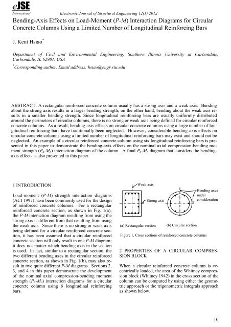
Load-moment (P-M) strength interaction diagrams<br />
(ACI 1997) have been commonly used <strong>for</strong> the design<br />
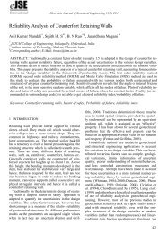
of rein<strong>for</strong>ced concrete columns. For a rectangular<br />
rein<strong>for</strong>ced concrete section, as shown in Fig. 1(a),<br />
the P-M interaction diagram resulting from using the<br />
strong axis is different from that resulting from using<br />
the weak axis. Since there is no strong or weak axis<br />
being defined <strong>for</strong> a circular rein<strong>for</strong>ced concrete section,<br />
it has been assumed that a circular rein<strong>for</strong>ced<br />
concrete section will only result in one P-M diagram;<br />
it does not matter which bending axis in the section<br />
is used. In fact, similar to a rectangular section, the<br />
two different bending axes in the circular rein<strong>for</strong>ced<br />
concrete section, as shown in Fig. 1(b), may also result<br />
in two quite different P-M diagrams. Sections 2,<br />
3, and 4 in this paper demonstrate the development<br />
of the nominal axial compression-bending moment<br />
strength (P n -M n ) interaction diagrams <strong>for</strong> a circular<br />
concrete column using 6 longitudinal rein<strong>for</strong>cing<br />
bars.<br />
Weak axis<br />
Strong axis<br />
(a) Rectangular section<br />
(b) <strong>Circular</strong> section<br />
Figure 1. Cross sections of rein<strong>for</strong>ced concrete columns<br />
Bending axes<br />
under<br />
consideration<br />
2 PROPERTIES OF A CIRCULAR COMPRES-<br />
SION BLOCK<br />
When a circular rein<strong>for</strong>ced concrete column is eccentrically<br />
loaded, the area of the Whitney compression<br />
block (Whitney 1942) in the cross section of the<br />
column can be computed by using either the geometric<br />
approach or the trigonometric integrals approach<br />
as shown below.<br />
10
Electronic Journal of Structural Engineering 12(1) 2012<br />
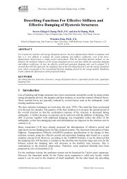
1. Geometric approach: Referring to Fig. 2, the<br />
area of a circular compression block can be obtained<br />
by subtracting the area of a triangular segment from<br />
the area of a circular segment.<br />
The area of the circular segment enclosed by the radius<br />
OA and OB and the arc AB can be computed as<br />
2<br />
h 2<br />
rad<br />
<br />
2 2<br />
<br />
<br />
<br />
rad<br />
2<br />
h<br />
<br />
4<br />
The area of the triangular segment enclosed by the<br />
radius OA and OB and the chord AB can be computed<br />
as<br />
<br />
<br />
<br />
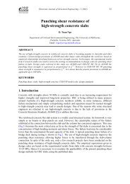
2. Trigonometric integrals approach: Referring to<br />
Fig. 3, the area of the circular compression block is<br />
<br />
h <br />
h <br />
A <br />
<br />
2<br />
sin <br />
sin d<br />
0 2 <br />
2 <br />
2<br />
h <br />
2<br />
<br />
<br />
sin d <br />
2 0<br />
2<br />
h rad<br />
1 <br />
sin 2<br />
<br />
2 2 4 <br />
Also, the location of the centroid of the circular<br />
compression block is<br />
h <br />
h <br />
1 h<br />
2<br />
sin cos<br />
<br />
2<br />
<br />
<br />
2<br />
<br />
<br />
<br />
2 4<br />
2<br />
<br />
sin cos<br />
There<strong>for</strong>e, the area of the circular compression block<br />
is<br />
2 2<br />
2<br />
h h<br />
h 1<br />
A <br />
<br />
2<br />
4 4<br />
2 2 4<br />
rad <br />
sin<br />
cos<br />
sin <br />
rad<br />
(1)<br />
<br />
0<br />
<br />
X <br />
<br />
h <br />
h <br />
h <br />
2<br />
sin <br />
cos<br />
<br />
sin d<br />
2 <br />
2 <br />
2 <br />
A<br />
3 3<br />
h sin <br />
<br />
4<br />
3<br />
<br />
<br />
A<br />
(2)<br />
y<br />
y<br />
( 2<br />
h ) cosα<br />
<strong>Circular</strong> Compression<br />
block<br />
A<br />
α<br />
( 2<br />
h ) sinα<br />
x<br />
O<br />
α<br />
α<br />
( 2<br />
h ) sinα<br />
X<br />
Centroid of<br />
compression<br />
block<br />
h<br />
B<br />
y<br />
( 2<br />
h ) cosθ<br />
A<br />
A<br />
A<br />
( 2<br />
h ) dθ sinθ<br />
O<br />
B<br />
<strong>Circular</strong><br />
compression<br />
block<br />
=<br />
O<br />
B<br />
<strong>Circular</strong><br />
segment<br />
O<br />
B<br />
Triangular<br />
segment<br />
dθ<br />
α<br />
θ<br />
( 2<br />
h ) dθ<br />
( 2<br />
h ) sinθ<br />
( 2<br />
h ) sinθ<br />
Figure 2. <strong>Circular</strong> compression block <strong>for</strong> bending about y-axis<br />
(geometric approach)<br />
h<br />
Figure 3. <strong>Circular</strong> compression block <strong>for</strong> bending about<br />
y-axis (trigonometric integrals approach)<br />
11
Electronic Journal of Structural Engineering 12(1) 2012<br />
a b = β 1 x b = 0.85 (263 mm) = 223.5 mm<br />
3 EXAMPLES OF THE COMPUTATION OF<br />
NOMINAL AXIAL COMPRESSION STRENGTH<br />
AND NOMINAL MOMENT STRENGTH<br />
'<br />
Note that the factor β 1 is 0.85 <strong>for</strong> fc<br />
≤ 27.6 MPa<br />
(4000 psi) (ACI 2008).<br />
y<br />
The following two examples demonstrate the computation<br />
of the nominal axial compression strength<br />
(P n ) and the nominal moment strength (M n ) <strong>for</strong> a circular<br />
spiral column rein<strong>for</strong>ced with six (6) longitudinal<br />
bars. The locations of the six longitudinal bars<br />
in both examples are symmetric about the bending<br />
axis (the y-axis). In Example 1, the bending axis<br />
goes through the centroid of the six bars but does not<br />
go through any of them (Fig. 4). In Example 2, the<br />
bending axis goes through two of the six bars, as<br />
well as the centroid of the six bars (Fig. 5). The statics<br />
method (Wang et al. 2007) is used <strong>for</strong> the computation<br />
of the P n and the M n values <strong>for</strong> these two<br />
examples.<br />
95.1 mm<br />
508 mm (20)<br />
60<br />
38.1 mm<br />
(1 1 / 2 ) cover<br />
#3 spiral<br />
95.1 mm<br />
63.8 mm<br />
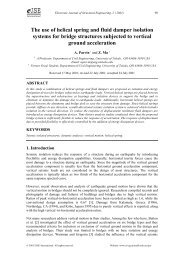
Example 1: Determine the nominal axial compression<br />
strength (P n ) and the nominal moment<br />
strength (M n ) <strong>for</strong> a balanced strain condition on the<br />
section of a circular spiral column rein<strong>for</strong>ced with 6-<br />
#10 (ASTM A615 bars (ASTM 2001)) longitudinal<br />
bars <strong>for</strong> bending about the y-axis as shown in Fig. 4.<br />
Given: The compressive strength of concrete, f =<br />
20.7 MPa (3 ksi); the yield stress of steel, f y = 414<br />
MPa (60 ksi); and the modulus of elasticity of steel,<br />
E s = 200,000 MPa (29,000 ksi). Note that the diameter<br />
of a #10 ASTM A615 bar is 32.3 mm<br />
(1.270") and the area of the bar, A s = 8.19 cm 2 (1.27<br />
in. 2 ); the diameter of a #3 ASTM A615 bar is 9.5<br />
mm (0.375"). Also note that a balanced strain condition<br />
exists at a cross section when the strain of the<br />
tension steel reaches ε y (the strain corresponding to<br />
f y ; i.e. ε y = f y /E s ) just as the maximum strain of the<br />
concrete in compression reaches its assumed ultimate<br />
strain of 0.003 (ACI 2008).<br />
1. Determine the location of the neutral axis:<br />
Referring to Fig. 4, the distance from extreme compression<br />
fibers to extreme tension steel, d t = 444.2<br />
mm. The yield strain of the steel, ε y = (f y /E s ) = (414<br />
MPa / 200,000 MPa) = 0.00207. The distance from<br />
the extreme compression fibers to the neutral axis<br />
<strong>for</strong> a balanced strain condition can be determined as<br />
0.003<br />
x b d<br />
t 263 mm<br />
0.003 ε<br />
y<br />
The depth of the Whitney equivalent rectangular<br />
stress distribution (Whitney 1942) in concrete <strong>for</strong> the<br />
balanced strain condition can be determined as<br />
'<br />
c<br />
ε y<br />
2. Calculate the properties of the circular compression<br />
block:<br />
Referring to Figs. 3 & 4,<br />
cos<br />
ε s3<br />
T 1 T 2<br />
1<br />
<br />
<br />
<br />
<br />
<br />
h<br />
2<br />
d t = 444.2 mm<br />
<br />
h<br />
2<br />
a b<br />
ε s2<br />
X<br />
<br />
<br />
cos<br />
<br />
<br />
83.1<br />
1.45 rad.<br />
C s2<br />
x b<br />
ε s1<br />
C c<br />
<br />
0.85 f<br />
' c<br />
1<br />
254mm 223.5mm <br />
<br />
<br />
254mm <br />
The area of the circular compression block can be<br />
computed using Eq. (1):<br />
a b<br />
C s1<br />
0.003<br />
Figure 4. Balanced strain condition of Example 1<br />
12
Electronic Journal of Structural Engineering 12(1) 2012<br />
<br />
<br />
2<br />
508 1.45<br />
1 <br />
A sin 166.2<br />
858.5cm 2<br />
2 2 4 <br />
The location of the centroid of the circular compression<br />
block can be determined using Eq. (2):<br />
X <br />
<br />
508<br />
4<br />
<br />
3<br />
3<br />
sin 83.1<br />
<br />
<br />
3<br />
<br />
124.5 mm<br />
85850<br />
3. Calculate the compressive <strong>for</strong>ce in concrete in<br />
the circular compression block:<br />
C c = 0.85<br />
f ' c A = 0.85(0.0207)(85850) = 1510 kN<br />
4. Calculate the strains and <strong>for</strong>ces in the tension<br />
and the compression steel:<br />
Referring to Fig. 4, the strains of the steel are<br />
ε s1 = 0.00227 (> ε y )<br />
ε s2 = 0.00119 (< ε y ), and<br />
ε s3 = 0.000984 (< ε y )<br />
The <strong>for</strong>ces in the steel are<br />
T 1 = A s f y = 819(0.414) = 339 kN<br />
= 379 kN·m (280 k·ft)<br />
Example 2: Determine the nominal axial compression<br />
strength (P n ) and the nominal moment<br />
strength (M n ) <strong>for</strong> a balanced strain condition on the<br />
section, as shown in Fig. 5. While the section and<br />
material properties of this example are the same as<br />
that given in Example 1, the bending axis of this example<br />
is perpendicular to that of Example 1.<br />
1. Determine the location of the neutral axis:<br />
Referring to Fig. 5, the distance from extreme compression<br />
fibers to extreme tension steel, d t = 418.8<br />
mm. The distance from the extreme compression fibers<br />
to the neutral axis <strong>for</strong> a balanced strain condition<br />
can be determined as<br />
x d<br />
247. 8 mm<br />
b<br />
0.003<br />
0.003 ε<br />
y<br />
t<br />
The depth of the Whitney equivalent rectangular<br />
stress distribution in concrete <strong>for</strong> the balanced strain<br />
condition can be determined as<br />
a b = β 1 x b = 0.85 (247.8 mm) = 210.6 mm<br />
y<br />
508 mm (20)<br />
38.1 mm<br />
(1 1 / 2 ) cover<br />
T 2 = A s ε s3 E s<br />
= 2(819)(0.000984) (200) = 322 kN<br />
C s1 = A s (f y – 0.85 f ' c )<br />
= 819[0.414 – 0.85(0.0207)] = 325 kN<br />
30<br />
#3 spiral<br />
C s2 = A s (ε s2 E s – 0.85 f ' c )<br />
= 2(819)[(0.00119) (200) – 0.85(0.0207)]<br />
= 361 kN<br />
Note that the value of (0.85 f ' c ) is the stress that has<br />
already been considered <strong>for</strong> the computation of the<br />
compressive <strong>for</strong>ce C c .<br />
164.8 mm<br />
ε y<br />
d t = 418.8 mm<br />
x b<br />
164.8 mm<br />
89.2 mm<br />
5. Calculate the nominal axial compression<br />
strength:<br />
ε s2<br />
ε s1<br />
a b<br />
0.003<br />
P n = C c + C s1 + C s2 – T 1 – T 2<br />
= 1535 kN (345 kips)<br />
T 1 T 2<br />
0.85 f<br />
' c<br />
6. Calculate the nominal moment strength:<br />
C s<br />
M n = [C c × X + (T 1 + C s1 )(190.2)<br />
1 <br />
+ (T 2 + C s2 )(95.1)] <br />
1000<br />
<br />
Figure 5. Balanced strain condition of Example 2<br />
X<br />
C c<br />
13
Electronic Journal of Structural Engineering 12(1) 2012<br />
2. Calculate the properties of the circular compression<br />
block:<br />
Referring to Figs. 3 & 5,<br />
254mm 210.6mm<br />
cos 1 <br />
<br />
80.16<br />
1.399 rad.<br />
254mm <br />
The area of the circular compression block can be<br />
computed using Eq. (1):<br />
<br />
<br />
2<br />
508 1.399<br />
1 <br />
A sin 160.3<br />
794 cm 2<br />
2 2 4 <br />
The location of the centroid of the circular compression<br />
block can be determined using Eq. (2):<br />
X <br />
<br />
508<br />
4<br />
<br />
3<br />
3<br />
sin 80.16<br />
<br />
<br />
3<br />
<br />
131.6 mm<br />
79400<br />
3. Calculate the compressive <strong>for</strong>ce in concrete in<br />
the circular compression block:<br />
C c = 0.85 f ' c A<br />
= 0.85(0.0207)(79400) = 1397 kN<br />
4. Calculate the strains and <strong>for</strong>ces in the tension<br />
and the compression steel:<br />
Referring to Fig. 5, the strains of the steel are<br />
ε s1 = 0.00192 (< ε y ), and<br />
ε s2 = 0.0000744 (< ε y )<br />
The <strong>for</strong>ces in the steel are<br />
T 1 = A s f y = 2(819)(0.414) = 678 kN<br />
T 2 = A s ε s2 E s<br />
= 2(819)(0.0000744) (200) = 24 kN<br />
C s = A s (ε s1 E s – 0.85 f ' c )<br />
= 2(819)[(0.00192) (200) – 0.85(0.0207)]<br />
= 600 kN<br />
5. Calculate the nominal axial compression<br />
strength:<br />
P n = C c + C s – T 1 – T 2 = 1295 kN (291 kips)<br />
6. Calculate the nominal moment strength:<br />
1<br />
M n = [C c × X + (C s + T 1 )(164.8)] <br />
1000<br />
= 394 kN·m (291 k·ft)<br />
The results derived from Examples 1 & 2 demonstrate<br />
the bending-axis effects on the balanced strain<br />
condition <strong>for</strong> a circular column with longitudinal<br />
bars. Due to the bending-axis effects, the M n value<br />
obtained from Example 1 <strong>for</strong> the balanced strain<br />
condition is different from that obtained from Example<br />
2. The M n value obtained from Example 1<br />
(379 kN·m) is about 96% of that obtained from Example<br />
2 (394 kN·m). Also, the P n value obtained<br />
from Example 2 <strong>for</strong> the balanced strain condition is<br />
different from that obtained from Example 1. The<br />
P n value obtained from Example 2 (1295 kN) is only<br />
about 84% of that obtained from Example 1 (1535<br />
kN).<br />
4 NOMINAL AXIAL COMPRESSION-BENDING<br />
MOMENT STRENGTH INTERACTION DIA-<br />
GRAMS<br />
By using the statics method, as shown in Examples 1<br />
& 2, the “P n ” value (the nominal axial compression<br />
strength) and the “M n ” value (the nominal bending<br />
moment strength) corresponding to each “a” value<br />
(the depth of the Whitney equivalent rectangular<br />
concrete stress distribution) are determined and are<br />
summarized, as shown in Tables 1 & 2. Table 1 is<br />
<strong>for</strong> the bending at axis location I (the location of the<br />
bending axis is shown in Example 1). Table 2 is <strong>for</strong><br />
the bending axis at location II (the location of the<br />
bending axis is shown in Example 2).<br />
Table 1. P n and M n data <strong>for</strong> the bending axis at location I (the<br />
location of the bending axis is shown in Example 1)<br />
a P n M n<br />
mm inches kN kips kN·m ft-kips<br />
508.0 20.00 5510 1239 0 0<br />
449.7 17.71 4684 1053 131 97<br />
428.6 16.87 4508 1014 160 118<br />
400.9 15.78 4219 949 198 146<br />
369.0 14.53 3844 864 241 178<br />
332.9 13.11 3396 763 282 208<br />
301.7 11.88 2937 660 315 232<br />
270.7 10.66 2430 546 343 253<br />
239.5 9.43 1857 418 367 271<br />
223.5 8.80 1535 345 379 280<br />
210.1 8.27 1295 291 379 280<br />
196.6 7.74 1037 233 378 279<br />
175.1 6.89 592 133 374 276<br />
142.7 5.62 147 33 329 243<br />
133.7 5.27 0 0 312 230<br />
<br />
<br />
14
Electronic Journal of Structural Engineering 12(1) 2012<br />
Table 2. P n and M n data <strong>for</strong> the bending axis at location II (the<br />
location of the bending axis is shown in Example 2)<br />
a P n M n<br />
mm inches kN kips kN·m ft-kips<br />
508.0 20.00 5510 1239 0 0<br />
454.6 17.90 4684 1053 121 89<br />
434.4 17.10 4508 1014 149 110<br />
402.6 15.85 4219 949 191 141<br />
369.7 14.55 3844 864 236 174<br />
334.6 13.18 3396 763 281 207<br />
302.3 11.90 2937 660 318 234<br />
270.1 10.63 2430 546 349 258<br />
236.7 9.32 1857 418 378 279<br />
221.3 8.71 1535 345 388 286<br />
210.6 8.29 1295 291 394 291<br />
194.3 7.65 1037 233 382 282<br />
168.6 6.64 592 133 356 263<br />
146.2 5.76 147 33 328 242<br />
139.6 5.50 0 0 318 234<br />
Fig. 6 presents the two P n -M n interaction diagrams<br />
<strong>for</strong> the circular column. One results from the bending<br />
axis at location I, while the other results from the<br />
bending axis at location II. Due to the bending-axis<br />
effects, the two diagrams deviate from each other<br />
and also intersect with each other at several points.<br />
Four zones are identified between the intersected<br />
points, as shown in Fig. 7. Each zone has two envelopes<br />
<strong>for</strong> the P n -M n diagram.<br />
P n (kN)<br />
6000<br />
5000<br />
4000<br />
3000<br />
Zone 1<br />
Series1<br />
Based on the data shown in Tables 1 & 2, the P n -<br />
M n interaction diagrams <strong>for</strong> the bending axis at locations<br />
I & II are constructed and are shown in Fig. 6.<br />
2000<br />
Zone 2<br />
P n (kN)<br />
6000<br />
5000<br />
4000<br />
Bending axis<br />
at location II<br />
1000<br />
Zone 3<br />
Zone 4<br />
0<br />
0 100 200 300 400 500<br />
M n (kN.m)<br />
3000<br />
Series1<br />
Figure 7. Bending axis effects on P n -M n interaction diagrams<br />
2000<br />
1000<br />
Bending axis<br />
at location I<br />
6 PROPOSED FINAL P n -M n INTERACTION DI-<br />
AGRAM<br />
0<br />
0 100 200 300 400 500<br />
M n (kN.m)<br />
Figure 6. P n -M n interaction diagrams <strong>for</strong> bending axis at<br />
locations I & II<br />
5 BENDING-AXIS EFFECTS ON P n -M n INTE-<br />
RACTION DIAGRAMS<br />
Within each zone as shown in Fig. 7, the envelope<br />
which goes through the smaller M n values is the one<br />
that controls the bending moment strength <strong>for</strong> that<br />
zone. Referring to Figs. 6 & 7, since the bending<br />
axis at location II results in smaller M n values in<br />
zones 1 & 3, it controls the envelopes in these two<br />
zones. Also, since the bending axis at location I results<br />
in smaller M n values in zones 2 & 4, it controls<br />
the envelopes in these two zones. Fig. 8 presents the<br />
proposed final P n -M n interaction diagram that takes<br />
the bending-axis effects into consideration <strong>for</strong> the<br />
circular column. Note that the final diagram was<br />
15
Electronic Journal of Structural Engineering 12(1) 2012<br />
constructed by using the controlling envelope in<br />
each zone.<br />
P n (kN)<br />
6000<br />
5000<br />
4000<br />
3000<br />
Series1<br />
and Commentary, American <strong>Concrete</strong> Institute,<br />
Farmington Hills, MI, 2008.<br />
American Society <strong>for</strong> Testing and Materials, Standard<br />
Specification <strong>for</strong> de<strong>for</strong>med and Plain Billet-<br />
Steel Bars <strong>for</strong> <strong>Concrete</strong> rein<strong>for</strong>cement,<br />
A615/A615M-01b, ASTM International, West<br />
Conshohocken, PA, 2001.<br />
Wang, C., Salmon, C. G., and Pincheira, J. A., Rein<strong>for</strong>ced<br />
<strong>Concrete</strong> Design (7 th ed.), John Willey &<br />
Sons, Inc., Hoboken, NJ, 2007.<br />
Whitney, C. S., “Plastic Theory of Rein<strong>for</strong>ced <strong>Concrete</strong><br />
Design”, Transactions ASCE, Vol. 107,<br />
1942, pp 251-326.<br />
2000<br />
1000<br />
0<br />
0 100 200 300 400 500<br />
7 CONCLUSIONS<br />
M n (kN.m)<br />
Figure 8. Final P n -M n interaction diagram<br />
Load-moment (P-M) strength interaction diagrams<br />
<strong>for</strong> rectangular and circular cross sections have been<br />
commonly used <strong>for</strong> the design of rein<strong>for</strong>ced concrete<br />
columns. Two P-M diagrams resulting from two<br />
bending axes (strong and weak axes) are usually<br />
used <strong>for</strong> the design of a rectangular rein<strong>for</strong>ced concrete<br />
column. However, since there is only one<br />
bending axis being considered <strong>for</strong> the design of a<br />
circular rein<strong>for</strong>ced concrete column, the bendingaxis<br />
effects on the P-M interaction diagrams <strong>for</strong> circular<br />
rein<strong>for</strong>ced concrete columns have traditionally<br />
been ignored. As demonstrated in this paper, the<br />
bending-axis effects on the P-M interaction diagrams<br />
<strong>for</strong> a circular concrete column using a limited number<br />
of longitudinal rein<strong>for</strong>cing bars are considerable<br />
and should not be neglected. A recommended P n -M n<br />
diagram, there<strong>for</strong>e, is proposed in this paper in order<br />
to take the bending-axis effects into consideration.<br />
NOTATION<br />
A = area of a circular compression block<br />
A s = area of rein<strong>for</strong>cement<br />
a = depth of Whitney equivalent rectangular<br />
stress distribution in concrete<br />
a b = depth of Whitney equivalent rectangular<br />
stress distribution in concrete <strong>for</strong> a balanced<br />
strain condition<br />
C c = compressive <strong>for</strong>ce in concrete in a circular<br />
compression block<br />
C s = compressive <strong>for</strong>ce in longitudinal rein<strong>for</strong>cement<br />
d t = distance from extreme compression concrete<br />
fibers to extreme tension rein<strong>for</strong>cement<br />
E s = modulus of elasticity of rein<strong>for</strong>cement<br />
'<br />
f c = specified compressive strength of concrete<br />
f y = specified yield strength of rein<strong>for</strong>cement<br />
M n = nominal moment strength<br />
P n = nominal axial load strength<br />
T = tensile <strong>for</strong>ce in longitudinal rein<strong>for</strong>cement<br />
X = location of the centroid of a circular com-<br />
x b =<br />
pression block<br />
distance from extreme compression fibers<br />
to the neutral axis <strong>for</strong> a balanced strain<br />
condition<br />
β 1 = the ratio a b / x b<br />
ε s = strain in longitudinal rein<strong>for</strong>cement<br />
REFERENCES<br />
American <strong>Concrete</strong> Institute, Design Handbook in<br />
Accordance with the Strength Design Method,<br />
American <strong>Concrete</strong> Institute, Farmington Hills,<br />
MI, 1997.<br />
American <strong>Concrete</strong> Institute, Building Code Requirements<br />
<strong>for</strong> Structural <strong>Concrete</strong> (ACI 318-08)<br />
16