Non-Contacting Steering Angle Sensor Type 6002 - we.CONECT
Non-Contacting Steering Angle Sensor Type 6002 - we.CONECT
Non-Contacting Steering Angle Sensor Type 6002 - we.CONECT

You also want an ePaper? Increase the reach of your titles
YUMPU automatically turns print PDFs into web optimized ePapers that Google loves.
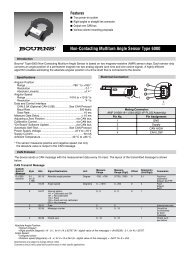
Features<br />
■ True po<strong>we</strong>r-on system<br />
■ Straight line connector<br />
■ Output over CAN bus<br />
■ Various column mounting proposals<br />
<strong>Non</strong>-<strong>Contacting</strong> <strong>Steering</strong> <strong>Angle</strong> <strong>Sensor</strong> <strong>Type</strong> <strong>6002</strong><br />
Introduction<br />
Bourns ® <strong>Type</strong> <strong>6002</strong> <strong>Non</strong>-contacting <strong>Steering</strong> <strong>Angle</strong> <strong>Sensor</strong> is based on two magneto-resistive (AMR) sensor chips. Each of them<br />
converts an angle position of a permanent magnet into two analogue signals (one sine and one cosine signal). A highly effi cient<br />
algorithm allows for estimating the absolute angular position of a drive shaft that is connected to the device.<br />
Specifications<br />
Angular Position<br />
Range ............................................................................ ±780 °<br />
Resolution ...............................................0.1 ° (optional 32767<br />
<strong>Angle</strong> Speed:<br />
• Unsigned (char)<br />
• Rotation speed [degree/s] = S · 0.4
<strong>Non</strong>-<strong>Contacting</strong> <strong>Steering</strong> <strong>Angle</strong> <strong>Sensor</strong> <strong>Type</strong> <strong>6002</strong><br />
CAN Protocol (Continued)<br />
Rule to build the check sum:<br />
Temp_result = lo<strong>we</strong>r byte<br />
(<strong>Angle</strong> position) XOR higher byte<br />
(<strong>Angle</strong> position) XOR (<strong>Angle</strong> speed)<br />
XOR<br />
(Internal status)<br />
Check sum = higher nibble<br />
(Temp_result) XOR lo<strong>we</strong>r nibble<br />
(Temp_result) XOR (Message counter)<br />
Automatic Self-Test<br />
The device checks the angular speed<br />
value, which is limited to 1016 degrees per<br />
second. If this limit exceeded, the device<br />
sends an error message according to the<br />
CAN Transmit Message (page 1).<br />
An example of the message layout for a receive message is shown below.<br />
CAN Receive Message<br />
CAN-ID<br />
Kind of<br />
Message Byte Bits Signal Destination Unit Measure<br />
Range<br />
0 x 7C0 0 0-3 Command word<br />
receive<br />
0 4-7 SAS transmit identifi er<br />
(SAS ID) bits 0-3<br />
1 8-14 SAS transmit identifi er<br />
(SAS ID) bits 4-10<br />
1 15 Free<br />
Command Word (CW)<br />
Measure<br />
Range<br />
(Digit)<br />
Offset<br />
Resolution<br />
(Unit/Digit)<br />
Comments<br />
CW bit3 CW bit2 CW bit1 CW bit0 Instruction<br />
0 0 1 1 Set up the zero position<br />
0 1 0 1 Clear the old zero position<br />
Other combinations<br />
Only for internal use<br />
Note:<br />
To set up a new zero position, fi rst it is necessary to delete the old zero position.<br />
Design and Mechanical Interface<br />
Housing - Device View<br />
MATERIAL IDENTIFICATION<br />
PER SAE J1344, METHOD 2<br />
RAISED<br />
0.3 - 0.4<br />
8.3 ± 0.08<br />
7.49 ± 0.5<br />
R5<br />
40.0 ± 0.5<br />
R2<br />
25.5<br />
4.0 ± 0.2<br />
R23<br />
32.7 ± 0.5<br />
DIA.<br />
R2<br />
R4<br />
6.2<br />
49.0<br />
60.1<br />
0.45 ± 0.3<br />
1.5 ± 0.2<br />
R12<br />
58.6<br />
1.6 ± 0.5<br />
R2<br />
R1<br />
27.5<br />
15.24 ± 0.5<br />
60.0<br />
DIMENSIONS: MM<br />
Specifi cations are subject to change without notice.<br />
Customers should verify actual device performance in their specifi c applications.
<strong>Non</strong>-<strong>Contacting</strong> <strong>Steering</strong> <strong>Angle</strong> <strong>Sensor</strong> <strong>Type</strong> <strong>6002</strong><br />
Linearity Data<br />
The fi rst graph shows a typical linearity measurement curve taken at room temperature. The second graph shows the deviation (absolute<br />
non-linearity) over four turns of the steering wheel.<br />
800<br />
600<br />
400<br />
200<br />
0<br />
-200<br />
-400<br />
-600<br />
Output Code and Absolute Linearity<br />
-800<br />
-800 -700 -600 -500 -400 -300 -200 -100 0 100 200 300 400 500 600 700 800<br />
0.3<br />
0.2<br />
0.1<br />
0<br />
-0.1<br />
-0.2<br />
-0.3<br />
-0.4<br />
-800 -700 -600 -500 -400 -300 -200 -100 0 100 200 300 400 500 600 700 800<br />
01/12<br />
Specifi cations are subject to change without notice.<br />
Customers should verify actual device performance in their specifi c applications.<br />
Europe:<br />
Bourns <strong>Sensor</strong>s GmbH<br />
Robert-Bosch-Str. 14<br />
D-82054 Sauerlach<br />
Phone: +49 (0) 8104 646-0<br />
The Americas:<br />
Bourns, Inc.<br />
1660 N. Opdyke Road, Ste. 200<br />
Auburn Hills, MI 48326-2655 USA<br />
Phone: +1 248 926-4088<br />
Asia:<br />
Bourns, Inc.<br />
10F, No. 146, Sung Jiang Road<br />
Taipei, Taiwan, 104 PRC<br />
Phone: +886 2 2562-4117<br />
www.bourns.com<br />
automotive@bourns.com