VH-SR Instruction Booklet - Discovermymobility.com
VH-SR Instruction Booklet - Discovermymobility.com
VH-SR Instruction Booklet - Discovermymobility.com

Create successful ePaper yourself
Turn your PDF publications into a flip-book with our unique Google optimized e-Paper software.
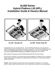
PARTS<br />
NOTE: VersaHaul is attached with your standard Hitch Pin (not included).<br />
www.versahaul.<strong>com</strong><br />
Outer Ramp<br />
Inner Ramp<br />
Ramp Base<br />
Stinger<br />
Toward Vehicle<br />
1. Read all instructions for future reference.<br />
2. Follow all warnings and instructions marked on the<br />
product.<br />
3. Do not stand on the VersaHaul.<br />
4. Do not ride any vehicle while loading onto the<br />
VersaHaul.<br />
5. Always store the VersaHaul in a safe place.<br />
6. Never exceed vehicle tongue weight ratings.<br />
7. Only use VersaHaul with Class 3 or 4 hitch. Most<br />
Class 3 hitches limit the VersaHaul to 500 lbs. total<br />
hauling capacity.<br />
LIMITED WARRANTY<br />
The Limited Warranty on the VersaHaul Carrier.<br />
WARNING<br />
8. Improper use, storage or installation of ramp could<br />
result in death or serious injury.<br />
9. Do not put any VersaHaul on a 5th wheel trailer or<br />
any other kind of trailer.<br />
10. <strong>VH</strong>-<strong>SR</strong> carrying capacity is limited to 300 lbs. max.<br />
Your vehicle suspension and hitch may limit the<br />
hauling capacity of the carrier. For more<br />
information on vehicles and hauling capacities, visit<br />
www.versahaul.<strong>com</strong>.<br />
BNK, INC warrants the carrier and related <strong>com</strong>ponents. This warranty applies to any part found to be defective due to<br />
material and/or workmanship when inspected at the factory of BNK, Inc., Winamac, IN. BNK Inc. will, at its option,<br />
repair or replace defective parts to the original purchaser at no charge other than transportation. Sale receipt as<br />
proof of date of purchase is required, which will be returned. BNK, Inc. assumes no liabilty for labor charges made in<br />
performance of this warranty.<br />
The warranty periods are as follows from date of purchase:<br />
mobility scooter safety ramp<br />
<strong>VH</strong>-<strong>SR</strong><br />
CARRIER FOR 1 YEAR, VOID IF: frame is broken or bent due to abuse. example: (underside scraped abusively)<br />
(1) Large Outer Ramp<br />
<strong>VH</strong>042<br />
(1) Ramp Base<br />
<strong>VH</strong>034<br />
(1) Safety Lanyard<br />
(2) Bolt<br />
1<br />
/2” x 2 1 /2”<br />
<strong>VH</strong>241<br />
ALL WARRANTIES ARE VOID IF: the carrier has been rented, used under abnormal conditions, or subjected to<br />
abuse, misuse, neglect, or improper maintenance.<br />
All warranties should be handled at point of purchase unless other arrangements are made.<br />
(1) Small Inner Ramp<br />
<strong>VH</strong>046<br />
<strong>VH</strong>047<br />
(1) License Plate<br />
Holder w/Light<br />
<strong>VH</strong>093<br />
(3) Pull Pin & Nut<br />
<strong>VH</strong>300<br />
<strong>VH</strong>310<br />
(2) 5 /16” Nut<br />
<strong>VH</strong>223<br />
BNK, Inc. is not liable for any damage claim or liability cliam, personal or otherwise resulting from operation of this<br />
carrier in any way. All transportation charges for items returned for warranty evaluation and/or replacement are to be<br />
borne by the customer.<br />
(1) Angled Stinger<br />
<strong>VH</strong>027<br />
(2) Safety U-Bolt<br />
(1) Eyebolt<br />
(2) 1 /2” Nut<br />
<strong>VH</strong>242<br />
For one (1) year from the date of purchase, BNK, Inc. will repair or replace for the original purchaser, without charge,<br />
any part or parts are manufactured by BNK, Inc. and found, upon examination at our factory in Winamac, to be<br />
defective in materials and/or workmanship.<br />
(1) Adjustable Slider<br />
<strong>VH</strong>035<br />
(2) Ramp Handle<br />
<strong>VH</strong>330<br />
(3) Bolt<br />
3<br />
/8” x 3 /4”<br />
<strong>VH</strong>232<br />
(2) 5 /16” Washer<br />
<strong>VH</strong>222<br />
All transportation charges on parts submitted for replacement under this warranty must be borne by the purchaser.<br />
This warranty does not apply to parts not manufactured by BNK, Inc. Their manufacturer may warrant these items.<br />
This warranty does not apply to any part which has been damaged by accident, alteration, abuse, improper<br />
adjustment, normal wear, or any other cause beyond our control.<br />
TOOLS<br />
(1) Stinger Cover<br />
<strong>VH</strong>023B<br />
(1) Anti-Tilt<br />
Lock Bracket<br />
<strong>VH</strong>070<br />
(2) Bolt<br />
5<br />
/16” x 2 1 /2”<br />
(2) 1 /2” Washer<br />
<strong>VH</strong>245<br />
Use of replacement parts other than genuine BNK, Inc. parts may impair the safety of your machine and void this<br />
warranty.<br />
IMPORTANT<br />
THIS WARRANTY IS VOID UNLESS THE PRODUCT REGISTRATION CARD IS FILLED OUT COMPLETELY AND<br />
RETURNED TO THE FACTORY AT WINAMAC, IN. WITHIN TEN (10) DAYS OF PURCHASE.<br />
½" Wrench 3<br />
/8" Wrench 5<br />
⁄₁₆" Wrench<br />
OUR WARRANTY COVERS OUR PRODUCT FOR ONE YEAR. WE ARE NOT ABLE TO EXCHANGE<br />
USED VERSAHAUL CARRIERS FOR REFUNDS OR NEW CARRIERS.<br />
BNK,Inc. 9341 S. St Rd. 39 Winamac, IN 46996 Problems? Questions? Call us at (888) 818-9915
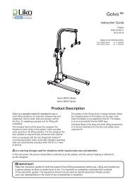
ASSEMBLING YOUR VERSAHAUL<br />
Angled Stinger<br />
1<br />
/2” Washer<br />
1 /2” Nut<br />
1<br />
/2” Stinger Bolt<br />
Stinger Cover<br />
Step 1<br />
Place the stinger cover over the end of the angled<br />
stinger and align the holes. Secure the two pieces<br />
together with the two 1 /2” x 2 1 /2” bolts, washers,<br />
and nuts.<br />
Outer Ramp<br />
Safety<br />
Handle<br />
Safety<br />
Loop<br />
mobility scooter safety ramp<br />
<strong>VH</strong>-<strong>SR</strong> INSTRUCTION DIAGRAM<br />
Step 6<br />
Attach the large outer ramp to the ramp base using the<br />
same method as in Step 5. Bolt on the handle and the<br />
safety loop on the side of the ramp. The expanded metal<br />
mesh ramp surface has been removed for illustrative<br />
clarity.<br />
Adjustable Slider<br />
3<br />
/8” x 3 /4” Stinger<br />
Lock Bolt<br />
Step 2<br />
Insert the adjustable slider into the stinger and secure at the<br />
desired length with the three 3 /8” x 3 /4” stinger lock bolts.<br />
Make sure all three bolts are secure against the slider.<br />
2<br />
1<br />
Safety Handle<br />
& Loop<br />
Placement<br />
Hole for Eyebolt<br />
Pull Pins and Nuts<br />
Eyebolt<br />
Angled Stinger<br />
Step 3<br />
Insert the ramp base into the adjustable slider and line<br />
up the holes on both pieces. Make sure the ramp base<br />
plate with holes is facing you if the stinger is pointing off<br />
to your right. Place the license plate cover over the holes<br />
and secure the three pieces together at the desired<br />
height with the two 5 /16” X 2 1 /2” adjustable bolts, nuts,<br />
and washers. License Plate Holder: Push the square<br />
plastic grommets for mounting the license plate through<br />
the square holes in the rounded tab. Pull the wires for<br />
the light through the large hole and fasten the light to<br />
the holder with the screws provided with the light. Make sure the light is facing towards the<br />
license plate.<br />
2<br />
Loop of Safety Lanyard<br />
goes around this pin<br />
Inner Ramp<br />
1<br />
Step 4<br />
Attach the smaller inner ramp on the stinger side. The small<br />
ramp must go on first. Slide the round pin through the hook<br />
on the right side of the ramp and tilt the ramp until the left<br />
hook attaches over the left flat pin. Bolt on the handle and<br />
the safety loop to the inner ramp.<br />
Closeup of Ramp<br />
Base Plate<br />
Safety<br />
Lanyard<br />
Ramp Base Plate<br />
with Holes<br />
5<br />
/16” x 2 1 /2” Bolt<br />
Ramp Base<br />
5<br />
/16” Washer<br />
5<br />
/16” Nut<br />
License<br />
Plate<br />
Holder<br />
Light<br />
Stinger<br />
Step 5<br />
Once in place, screw in the left two pull pins to<br />
lock both ramps in place. On the rightmost pull<br />
pin, remove the nut and place the lanyard look<br />
around the pin. The loop will have to go over the<br />
threads on the pull pin. Screw the pin in place to<br />
secure the lanyard and fasten all pull pins with<br />
nuts. Screw in eye bolt to secure safety lanyard.<br />
Handle<br />
Safety Loop<br />
Safety Loop<br />
Handle<br />
Safety Lanyard<br />
Eyebolt for securing<br />
safety lanyard latch<br />
Step 7<br />
Run the latch end of the safety lanyard through<br />
the loops and secure to the eye bolt.<br />
ATTACHING YOUR VERSAHAUL<br />
Step 1 Step 2<br />
Mount the three 3 /8” bolts to the<br />
Insert main tube into vehicle’s<br />
included Anti-Tilt Lock Bracket.<br />
receiver hitch and install hitch pin<br />
Insert bracket to the main tube<br />
(not included).<br />
as shown.<br />
Step 3<br />
Put the bracket flush against the hitch collar. Tighten the center bolt until it fits snugly<br />
against the receiver hitch underside. Tighten the two side bolts; then re-tighten the center<br />
bolt. Make sure all bolts are tight enough such than no slack exists between the main tube<br />
and the hitch. Note: Road vibration may cause bolts to loosen over time. Test by rocking<br />
the carrier from the sides. Minor deformation is normal on the contact area between the<br />
main tube and the anti-tilt bracket.<br />
Alternative <strong>Instruction</strong>s<br />
If the Anti-Tilt Lock Bracket does not fit, use the Anti-Tilt Hitch Attachment Bolt. The Anti-Tilt Hitch Attachment<br />
Bolt has a 7 /18” thread size, a 3 /8“ Allen Head size, and a 5 /8” outer Bolt Head Side View Top View<br />
head size. Slide the Main Tube of the carrier into the hitch receiver.<br />
Secure the Main Tube to the receiver with the Anti-Tilt Bolt, Washer<br />
and Nut. The Bolt must be inserted into the 7 /16” hole, not the 5 /8”<br />
hole. Note: Do not put a washer at the bolt head, but rather at the<br />
nut. The bolt head should be recessed into the receiver hole and be<br />
putting pressure on the Main Tube of the Carrier inside the receiver.<br />
Carrier Main Tube<br />
Hitch<br />
For more information on your VersaHaul, please visit www.versahaul.<strong>com</strong> Problems? Questions? Call us at (888) 818-9915