Left Foot Gas Pedal Model 3545 Installation and Owners Manual
Left Foot Gas Pedal Model 3545 Installation and Owners Manual
Left Foot Gas Pedal Model 3545 Installation and Owners Manual

Create successful ePaper yourself
Turn your PDF publications into a flip-book with our unique Google optimized e-Paper software.
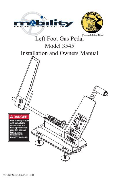
<strong>Left</strong> <strong>Foot</strong> <strong>Gas</strong> <strong>Pedal</strong><br />
<strong>Model</strong> <strong>3545</strong><br />
<strong>Installation</strong> <strong>and</strong> <strong>Owners</strong> <strong>Manual</strong><br />
Personally Driver Fitted<br />
DANGER<br />
Use of this product<br />
with adjustable<br />
accelerator <strong>and</strong><br />
brake pedals may<br />
result in serious<br />
bodily injury,<br />
death <strong>and</strong>/or<br />
property damage.<br />
PATENT NO.: US 6,494,115 B1
Information<br />
Many states either require or recommend that<br />
anyone using our products have a driver<br />
evaluation prior to installation.<br />
We recommend all customers have a driver<br />
evaluation performed by a qualified evaluator.<br />
If you should need assistance contact<br />
www.driver-ed.org<br />
or<br />
Discover Your Mobility Inc.<br />
at toll free 866-868-9694.<br />
www.discovermymobility.com
Table of Contents<br />
Warnings <strong>and</strong> Cautions . . . . . . . . . . . . . . . . . . . . . . . . . . . . . . . . 2<br />
Determining Base Plate Location . . . . . . . . . . . . . . . . . . . . . . . . 3<br />
Marking Base Plate Location . . . . . . . . . . . . . . . . . . . . . . . . . . . 4<br />
Mounting <strong>Left</strong> <strong>Foot</strong> <strong>Gas</strong> <strong>Pedal</strong> Base <strong>and</strong> Base Plate . . . . . . . . . . 4<br />
Attaching <strong>Left</strong> <strong>Foot</strong> <strong>Gas</strong> <strong>Pedal</strong> to Base . . . . . . . . . . . . . . . . . . . . 5<br />
Adjusting <strong>Left</strong> <strong>Foot</strong> <strong>Gas</strong> <strong>Pedal</strong> Position. . . . . . . . . . . . . . . . . . . . 6<br />
Removing <strong>Left</strong> <strong>Foot</strong> <strong>Gas</strong> <strong>Pedal</strong> From Base . . . . . . . . . . . . . . . . . 7<br />
Post <strong>Installation</strong> Dealer Inspection . . . . . . . . . . . . . . . . . . . . . . 7-8<br />
<strong>Left</strong> <strong>Foot</strong> <strong>Gas</strong> <strong>Pedal</strong> Operating Instructions. . . . . . . . . . . . . . . . . 9<br />
Maintenance. . . . . . . . . . . . . . . . . . . . . . . . . . . . . . . . . . . . . 10-11<br />
Warranty . . . . . . . . . . . . . . . . . . . . . . . . . . . . . . . . . . . . . . . 12-13<br />
Parts Listing. . . . . . . . . . . . . . . . . . . . . . . . . . . . . . . . . . . . . 14-15<br />
WARNING:<br />
NOT RECOMMENDED FOR TRANSFER<br />
FROM ONE VEHICLE TO THE NEXT<br />
FOR ASSISTANCE OR PARTS<br />
Call: (866) 868-9694<br />
Fax: (574) 542-2132<br />
1<br />
90524-000 Revision G
CAUTION<br />
INDICATES A POTENTIALLY<br />
HAZARDOUS SITUATION THAT,<br />
IF NOT AVOIDED COULD<br />
CAUSE DAMAGE TO THE PRODUCT,<br />
VEHICLE, OR MODERATE INJURY<br />
TO THE INSTALLER OR OTHER<br />
PEOPLE.<br />
Warnings <strong>and</strong> Cautions<br />
WARNING<br />
INDICATES A POTENTIALLY<br />
HAZARDOUS SITUATION THAT,<br />
IF NOT AVOIDED COULD<br />
CAUSE SERIOUS BODILY INJURY<br />
AND / OR PROPERTY DAMAGE.<br />
General <strong>Installation</strong> <strong>and</strong> Operation Warnings<br />
THIS PRODUCT MUST BE INSTALLED ONLY BY AN<br />
AUTHORIZED MOBILITY PRODUCTS & DESIGN DEALER.<br />
ONLY TRAINED OPERATORS MUST OPERATE THIS DEVICE.<br />
KEEP THE DEVICE MAINTAINED REGULARLY. (ACCORDING<br />
TO THE MAINTENANCE RECOMMENDATIONS)<br />
INSPECT THE DEVICE PRIOR TO EVERY OPERATION.<br />
DO NOT USE THE ACCELERATOR GUARD AS A FOOT REST.<br />
REFER TO FIGURE 5.<br />
IF SOMEONE OTHER THAN THE TRAINED OPERATOR IS USING<br />
THE VEHICLE, THE LEFT FOOT GAS PEDAL MUST BE<br />
REMOVED. REFER TO FIGURE 7.<br />
PLACE THE WARNING DECAL ON THE INSIDE OF THE<br />
VEHICLE WINDSHIELD. DECAL MUST BE VISIBLE BY THE<br />
DRIVER WHEN SEATED AND MUST NOT IMPAIR VISIBILITY.<br />
THE LEFT FOOT GAS PEDAL IS TO BE USED ON VEHICLES<br />
EQUIPPED WITH AUTOMATIC TRANSMISSION ONLY.<br />
READ AND UNDERSTAND THIS MANUAL PRIOR TO<br />
INSTALLING AND OPERATING.<br />
DO NOT INSTALL THE BASE PLATE ON TOP OF FLOOR MATS<br />
OR ANY OTHER LOOSE FLOOR COVERING NOT ATTACHED BY<br />
VEHICLE'S ORIGINAL MANUFACTURER.<br />
2
Step 1) Determining Base Plate Location<br />
With the Base attached to the LFGP (<strong>Left</strong><br />
<strong>Foot</strong> <strong>Gas</strong> <strong>Pedal</strong>) assembly, follow these three<br />
steps to determine the Base Plate location.<br />
WARNING<br />
This product must be<br />
installed only by an<br />
authorized MPD dealer<br />
1A) <strong>Left</strong> to Right: A 3/16” (approx.) gap should be visible<br />
between the flat part of the Actuator Arm Assembly <strong>and</strong> the OEM<br />
gas pedal.<br />
Figure 1<br />
3/16”<br />
Correct Wrong Wrong<br />
1B) Front to Back: The adjustable slide of the Actuator Arm<br />
should be parallel with the OEM gas pedal.<br />
Figure 2<br />
Incorrect spacing<br />
1/2”<br />
Minimum<br />
Correct Wrong<br />
Acceptable on<br />
inclined floor<br />
1C) Actuator Arm Adjustment: For OEM (Original Equipment<br />
Manufacturer) gas pedals with a pivot: The Roller should be located<br />
above <strong>and</strong> close to the pivot (roller must not be<br />
located even with, or below the OEM gas pedal pivot point). For<br />
solid OEM gas pedals (no pivot): The Roller should be located<br />
between the top 1 ⁄2 <strong>and</strong> 3 ⁄4 of the OEM gas pedal.<br />
Figure 3<br />
Correct Wrong Wrong<br />
3<br />
WARNING<br />
IMPROPER ADJUSTMENT OR<br />
INSTALLATION OF THE LEFT FOOT<br />
GAS PEDAL, MAY RESULT IN THE<br />
OEM PEDAL BEING LOCKED IN<br />
THE PARTIAL OR FULL ACTIVATION<br />
POSITION<br />
Accelerator<br />
Pivot
Once the proper<br />
location of the <strong>Left</strong><br />
<strong>Foot</strong> <strong>Gas</strong> <strong>Pedal</strong> is<br />
determined, mark by<br />
placing tape along 2<br />
edges of the Lockout<br />
Base.<br />
Step 2) Marking Base Plate Location<br />
CAUTION<br />
Prior to drilling the<br />
mount holes, check<br />
for obstructions<br />
such as wiring, fuel<br />
lines, etc. under the<br />
carpet <strong>and</strong> vehicle<br />
floor<br />
Step 3) Mount LFGP <strong>and</strong> Base Plate<br />
Place LFGP Base Plate on the floor in the area previously marked<br />
(the slot in Base Plate should be toward the front, left side as<br />
shown in figure 4).<br />
Check under vehicle <strong>and</strong> under the carpet to make sure you don’t<br />
drill into unwanted objects (such as… gas lines, brake lines, wires,<br />
etc.).<br />
Using the Base Plate as a template, drill four holes for the<br />
mounting bolts using a 9/32” drill bit.<br />
Secure LFGP Base Plate, Spacers, <strong>and</strong> Base to the floor using the<br />
bolts provided.<br />
Figure 4<br />
1/4” Bolts<br />
Lockout Base<br />
Spacers (2)<br />
Base Plate<br />
WARNING<br />
Do not install the Base<br />
Plate on the top of floor<br />
mats or any other loose<br />
floor covering not<br />
attached by the vehicles<br />
original manufacturer.<br />
1/4” Fender Washers<br />
1/4” Nylock Nuts<br />
(torque to 50 to 70<br />
in./lbs<br />
4
Step 4) Attach LFGP to Base<br />
A. Hold on to the LFGP Accelerator Guard <strong>and</strong> Actuator Arm with<br />
one h<strong>and</strong>.<br />
B. Push the LFGP down into the slots of the Base.<br />
C. Slide the LFGP to the right until it latches. At this time be sure<br />
the LFGP is secure <strong>and</strong> the Latch is completely<br />
engaged. Refer to caution note.<br />
CAUTION<br />
1) If the red mark on the latch is visible, unit is<br />
not latched. Do not use until securely latched.<br />
2) This device has been adjusted for this<br />
vehicle. Do not use in other vehicles.<br />
Figure 5<br />
STEP C<br />
STEP B<br />
Actuator Arm<br />
Accelerator Guard<br />
5
Step 5) Adjusting <strong>Left</strong> <strong>Foot</strong> <strong>Gas</strong> <strong>Pedal</strong> Position<br />
Dimension A is equal to Dimension B: Distance (left to right)<br />
between OEM <strong>Gas</strong> <strong>Pedal</strong> <strong>and</strong> OEM Brake <strong>Pedal</strong> should be the<br />
same as the distance between OEM Brake <strong>Pedal</strong> <strong>and</strong> LFGP.<br />
You must be able to completely activate the Emergency Brake<br />
without interfering with the <strong>Left</strong> <strong>Foot</strong> <strong>Gas</strong> <strong>Pedal</strong>. (Dimension C<br />
<strong>and</strong> D)<br />
Dimension E: Distance (front to back) between OEM <strong>Gas</strong> <strong>and</strong><br />
Brake <strong>Pedal</strong>s should be approximately the same as<br />
distance between LFGP <strong>and</strong> OEM Brake <strong>Pedal</strong>.<br />
WARNING<br />
If it is not possible to make dimension<br />
B equal to dimension A, DO NOT<br />
use the LFGP in this vehicle.<br />
Figure 6<br />
D<br />
E<br />
OEM Emergency<br />
Brake B<br />
C<br />
A<br />
OEM Brake<br />
<strong>Pedal</strong><br />
Trim excess rod off<br />
at this point.<br />
Trim off any excess rod length on the bottom Activator Arm.<br />
Install the Warning Decal on the<br />
vehicle windshield or drivers window.<br />
6<br />
W RNING A<br />
This vehicle has been<br />
modified with an Adaptive<br />
Driving Device - to be used by<br />
trained <strong>and</strong> licensed<br />
operators only!<br />
90051-000
Step 6) Removing LFGP From Base<br />
A. Lift the key ring on LFGP assembly.<br />
B. While lifting <strong>and</strong> holding the key ring up, slide the Lockout<br />
Base to the left.<br />
C. When the assembly begins to move, release the key ring <strong>and</strong><br />
continue to slide the assembly left until it can be lifted out of<br />
Base.<br />
Step B<br />
Figure 7<br />
Step C<br />
Step A<br />
Step 7) Post <strong>Installation</strong> Inspection by Installing<br />
Dealer<br />
1) Make sure that all the fasteners are secure <strong>and</strong> the Base is rigid<br />
with the vehicle floor.<br />
2) Verify the <strong>Left</strong> <strong>Foot</strong> <strong>Gas</strong> <strong>Pedal</strong> latching mechanism works<br />
properly by removing <strong>and</strong> attaching the mechanism three or<br />
more times. When attaching, notice:<br />
A) The Base latches in the slots with minimal effort.<br />
The latch should engage so the red line on the latch<br />
does not show.<br />
B) When removing, the latch should disengage<br />
smoothly, <strong>and</strong> the Base should slide out of the slots<br />
with little effort. It should not be necessary to use any<br />
tools to remove the LFGP from the Base.<br />
7
Post <strong>Installation</strong> Inspection Continued<br />
3) Verify correct operation of the <strong>Left</strong> <strong>Foot</strong> <strong>Gas</strong> <strong>Pedal</strong>:<br />
A) With the engine off, make sure the LFGP operates<br />
freely <strong>and</strong> has the proper clearances outlined in these<br />
instructions.<br />
B) Verify the force it takes to operate the <strong>Left</strong> <strong>Foot</strong><br />
<strong>Gas</strong> <strong>Pedal</strong> is similar to the force it takes to operate<br />
the OEM accelerator.<br />
C) Verify the operation is a smooth motion. It should<br />
not stick at any point.<br />
D) Completely<br />
depress LFGP. It must<br />
not lock in a partial or<br />
fully accelerated<br />
position.<br />
8<br />
WARNING<br />
IMPROPER ADJUSTMENT OR<br />
INSTALLATION OF THE LEFT FOOT<br />
GAS PEDAL, MAY RESULT IN THE<br />
OEM PEDAL BEING LOCKED IN<br />
THE PARTIAL OR FULL ACTIVATION<br />
POSITION<br />
4) Press on the Accelerator Guard lightly to determine that it<br />
will not contact the Actuator Arm. If it does, refer to step 1B<br />
to readjust<br />
5) Make sure the OEM Parking Brake <strong>Pedal</strong> or mechanism<br />
does not activate or interfere with the operation of the LFGP.<br />
6) Test drive the vehicle yourself, after installation or any<br />
adjustments, to ensure the LFGP is functioning properly. Verify<br />
that the vehicle will go into passing gear <strong>and</strong> return to idle.<br />
7) Make sure the customer has had proper training by a<br />
Certified Driver Rehabilitation Specialist.<br />
8) Ensure the <strong>Left</strong> <strong>Foot</strong> <strong>Gas</strong> <strong>Pedal</strong> has been adjusted for the<br />
driver’s comfort <strong>and</strong> fit.<br />
9) Record vehicle information on<br />
decal located on back side of<br />
Accelerator Guard. (To ensure that<br />
if the LFGP is removed, it is<br />
reattached into the same vehicle.)<br />
10) Give this manual to the customer.<br />
Vehicle I.D.<br />
Year 2002 Make Dodge<br />
<strong>Model</strong> Caravan
<strong>Left</strong> <strong>Foot</strong> <strong>Gas</strong> <strong>Pedal</strong> Operating Instructions<br />
We recommend all customers have a driver evaluation performed<br />
by a qualified evaluator.<br />
The <strong>Left</strong> <strong>Foot</strong> <strong>Gas</strong> <strong>Pedal</strong> transfers the force of the drivers left foot to<br />
the OEM accelerator pedal. It operates the same way as the OEM<br />
accelerator pedal, except the left foot is used instead of the right<br />
foot.<br />
The <strong>Left</strong> <strong>Foot</strong> <strong>Gas</strong> <strong>Pedal</strong> can be quickly attached (refer to step 4,<br />
figure 5) <strong>and</strong> is to be used by TRAINED OPERATORS ONLY.<br />
The <strong>Left</strong> <strong>Foot</strong> <strong>Gas</strong> <strong>Pedal</strong> is designed to be quickly detached (refer<br />
to step 6, figure 7) <strong>and</strong> MUST BE REMOVED IF SOMEONE<br />
OTHER THAN THE TRAINED OPERATOR IS USING THE<br />
VEHICLE.<br />
The accelerator guard is designed to guard the OEM accelerator<br />
from unintentional operation. The accelerator guard is NOT A<br />
FOOT REST. Except for performing a post installation<br />
inspection, DO NOT PUSH ON THE ACCELERATOR GUARD<br />
FOR ANY REASON.<br />
Alternate between the LFGP <strong>and</strong> the brake with left foot to further<br />
familiarize yourself with the function.<br />
Before each use:<br />
Make sure the <strong>Left</strong> <strong>Foot</strong> <strong>Gas</strong> <strong>Pedal</strong> is properly<br />
seated in the Base, <strong>and</strong> the red mark is not visible.<br />
Make sure the <strong>Left</strong> <strong>Foot</strong> <strong>Gas</strong> <strong>Pedal</strong> operates<br />
freely <strong>and</strong> properly.<br />
Make sure nothing is obstructing the operation of<br />
the <strong>Left</strong> <strong>Foot</strong> <strong>Gas</strong> <strong>Pedal</strong> (i.e.. Keep floor clean of<br />
rocks, mud, ice, <strong>and</strong> any form of debris)<br />
Make sure all fasteners are secure.<br />
9
Maintenance<br />
As the owner <strong>and</strong> user of the <strong>Left</strong> <strong>Foot</strong> <strong>Gas</strong> <strong>Pedal</strong>, it is your<br />
obligation to follow through with the required maintenance.<br />
Regular cleaning is required to ensure optimum performance.<br />
It is required that every 3 months:<br />
Vacuum out the Base <strong>and</strong> clean out any debris from under<br />
the Base.<br />
Verify that the LFGP Roller moves freely.<br />
Verify that the LFGP Latch moves freely. If needed, a drop<br />
of light weight oil may be applied to the latch, latch pin,<br />
<strong>and</strong>/or spacer. Remove any excess oil.<br />
It is required that every 6 months:<br />
Have an authorized Mobility Products & Design dealer<br />
inspect, <strong>and</strong> maintain the unit. Document any work<br />
completed on the chart provided.<br />
10
Dealer<br />
Signature<br />
Date<br />
Maintenance or Service<br />
Performed<br />
Parts<br />
Replaced<br />
11
Warranty Policy<br />
Mobility Products & Design products are warranted to be free from defects in material<br />
<strong>and</strong> workmanship for a period of two (2) years from the date of the original customer’s<br />
purchase. All warning messages on labels must be adhered to strictly, <strong>and</strong> regular<br />
maintenance procedures must be followed.<br />
This Warranty is effective only if the products or parts of the product have been installed<br />
in accordance with Mobility Products & Design’s written recommendations <strong>and</strong> with<br />
established installation practices <strong>and</strong> by an authorized dealer of Mobility Products &<br />
Design. Mobility Products & Design does not assume liability for defective products not<br />
manufactured or supplied by it, even though some products are used in conjunction with<br />
Mobility Products & Design products. Any <strong>and</strong> all claims for Warranty adjustments must<br />
be originated within the twenty-four (24) months Warranty period <strong>and</strong> must be submitted<br />
by an authorized Mobility Products & Design dealer in accordance with established<br />
Mobility Products & Design Warranty Claim procedures. The properly completed<br />
Warranty Registration must be on file at the office of Mobility Products & Design, for<br />
any Warranty claim to be considered. The Warranty period begins upon installation of the<br />
product or the date the product is placed in service.<br />
If, within such a Warranty period, any part of the product shall be proved to Mobility<br />
Products & Design’s satisfaction to be defective, such part shall be repaired or replaced at<br />
Mobility Products & Design’s option. Mobility Products & Design’s sole obligation <strong>and</strong><br />
the customer’s exclusive remedy, hereunder, shall be limited to such part repair or<br />
replacement.<br />
Service under this Warranty is available from the authorized Mobility Products & Design<br />
dealer who installed the equipment. If such dealer is not available, you may call<br />
(800) 488-7688 for the name of another servicing dealer or visit our website<br />
www.mobilityproductsdesign.com <strong>and</strong> click on Dealer Locator.<br />
NO RETURNS WILL BE ACCEPTED WITHOUT FIRST OBTAINING A SHIPPING<br />
AUTHORIZATION AND WARRANTY AUTHORIZATION RETURN GOOD<br />
NUMBER FROM MOBILITY PRODUCTS & DESIGN SHIPMENTS SENT FREIGHT<br />
COLLECT OR C.O.D. WILL BE REFUSED, UNLESS PREVIOUSLY AUTHORIZED.<br />
Mobility Products & Design, reserves the right to inspect any product or part which is<br />
subject of a Warranty claim in order to make final determination of the validity of such<br />
claim. Damage due to misuse, improper maintenance, improper installation, or damage<br />
from mishap or collision, is not covered.<br />
In any event, Mobility Products & Design’s liability extends only to the repair or<br />
replacement of such components as are necessary to restore the product to normal<br />
operating condition. All other claims or liabilities are expressly denied.<br />
12
This Warranty states the entire liability of Mobility Products & Design with respect to<br />
the products it manufactures. It is exclusive; <strong>and</strong> in lieu of all warranties expressed or<br />
implied, including but not limited to implied warranties of merchantability <strong>and</strong> fitness<br />
for particular use unless applicable by law, <strong>and</strong> then shall not extend beyond the<br />
minimum law or the duration of the express Warranty whichever is less. Under no<br />
circumstances will Mobility Products & Design be responsible for incidental or<br />
consequential damage arising out of the use of any of it’s products or any breach of this<br />
warranty, <strong>and</strong> any such damages are specifically excluded from this Warranty.<br />
Some states do not allow limitations on how long implied warranties last, so the above<br />
limitation with respect to implied warranties may not apply. Some states do not allow the<br />
exclusion or limitation of incidental, or consequential damages, so the above limitation<br />
or exclusion with respect to incidental or consequential damages may not apply.<br />
This Warranty gives you, the customer, specific legal rights <strong>and</strong> you may have other<br />
rights which vary from state to state.<br />
AGAIN, THE WARRANTY REGISTRATION CARD MUST BE COMPLETELY<br />
FILLED OUT, SIGNED AND IN POSSESSION OF MOBILITY PRODUCTS &<br />
DESIGN’S WARRANTY DEPARTMENT WITHIN THIRTY (30) DAYS AFTER<br />
INSTALLATION TO BE RECORDED AND RECOGNIZED. NO WARRANTY WILL<br />
BE AUTHORIZED UNLESS THIS IS COMPLETED.<br />
This Warranty is to the original purchaser only <strong>and</strong> is not transferable, <strong>and</strong> applies only<br />
to vehicles with power brakes, power steering <strong>and</strong> automatic transmission. Any products<br />
installed on vehicles without these features is strictly prohibited.<br />
This Warranty extends only to those products that are installed or used in transportation<br />
vehicles. Any other use of any of the products manufactured by Mobility Products &<br />
Design, other than as prescribed, are not authorized by Mobility Products & Design, <strong>and</strong><br />
Mobility Products & Design will make no warranty with respect to such<br />
non-conforming, unauthorized use or installation. Any changes to the product by any<br />
person or dealer, will also cause the Warranty to be null <strong>and</strong> void. Any person or dealer<br />
who uses or installs any product of Mobility Products & Design for a use other than<br />
stated above, does so at their own risk with the full knowledge <strong>and</strong> underst<strong>and</strong>ing that<br />
the Warranty is null <strong>and</strong> void. Any use other than in transportation vehicles for<br />
h<strong>and</strong>icapped persons, unless agreed to <strong>and</strong> approved in writing by the company shall<br />
render the Warranty null <strong>and</strong> void.<br />
This Warranty will not apply if the product is used or submitted in contests or testing<br />
programs. Your vehicle must conform to all Federal Motor Vehicle Safety St<strong>and</strong>ards<br />
(FMVSS) for the Warranty to be valid.<br />
13
Parts Diagram<br />
90442-000<br />
Serial Number<br />
Mount under asm.<br />
behind front edge<br />
90523-000<br />
Mount on top<br />
of unit.<br />
90529-000<br />
Mount on<br />
Accelerator<br />
Guard<br />
W A RNING<br />
This vehicle has been<br />
modified with an Adaptive<br />
Driving Device - to be used by<br />
trained <strong>and</strong> licensed<br />
operators only! 90051-000<br />
90549-000<br />
Vehicle ID decal<br />
located behind<br />
Accelerator Guard<br />
<strong>Model</strong><br />
Vehicle I.D.<br />
Year Make<br />
90051-000<br />
mount on windshield<br />
14
Parts Listing<br />
ITEM PART NO. QTY DESCRIPTION<br />
1 N/A 1 NOT SOLD SEPARATELY<br />
2 91252-000 2 NYLINER<br />
3 69185-000 1 WELD, LFGP BOTTOM ACTUATOR ARM<br />
4 69751-000 1 ASSEMBLY, LFGP UPPER ACTUATOR ARM<br />
5 69144-000 1 COLLAR, LEFT FOOT GAS PEDAL<br />
6 69193-000 1 LFGP LOCKOUT BASE<br />
7 69198-000 2 LFGP SPACER<br />
8 69194-000 1 LFGP LOCKOUT BASE PLATE<br />
9 69141-000 1 CLAMP<br />
10 69221-000 1 LFGP CLAMP PLATE<br />
11 69195-000 1 LFGP PEDAL<br />
12 81068-000 2 1/4 - 20 x 3/4 BHCS SS<br />
13 81090-000 4 1/4 - 20 x 2 BHCS SS<br />
14 82008-000 4 1/4 WASHER, FENDER<br />
15 83011-000 6 1/4 - 20 NUT, NYLOCK<br />
16 99296-000 1 LFGP SAFETY TRACK<br />
17 84027-000 1 1/4 - 20 x 1/4 SET SCREW<br />
18 82013-000 3 1/4 WASHER FLAT SAE<br />
19 80013-000 2 1/4 - 20 x 3/4 HHCS<br />
15