Assembly instructions MA207 (pt_en) - Multi-Contact
Assembly instructions MA207 (pt_en) - Multi-Contact
Assembly instructions MA207 (pt_en) - Multi-Contact

You also want an ePaper? Increase the reach of your titles
YUMPU automatically turns print PDFs into web optimized ePapers that Google loves.
Advanced <strong>Contact</strong> Technology<br />
MA000 <strong>MA207</strong> (de_<strong>en</strong>) (<strong>pt</strong>_<strong>en</strong>)<br />
Montageanleitung<br />
Instruções de montagem<br />
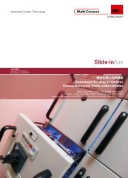
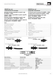
Acoplam<strong>en</strong>to fêmea PV-KBT3...<br />
Acoplam<strong>en</strong>to macho PV-KST3...<br />
Sumário<br />
Instruções de segurança ............................................................2<br />
Ferram<strong>en</strong>tas necessárias ...........................................................3<br />
Cabo de ligação .........................................................................4<br />
Preparação do cabo ...................................................................4<br />
Ligações por cravam<strong>en</strong>to ..........................................................4<br />
Cravar ........................................................................................5<br />
— com alicate de cravar PV-CZM-16100A .................................5<br />
— com alicate de cravar PV-CZ ..................................................6<br />
Montagem .................................................................................6<br />
Passagem do cabo ....................................................................8<br />
Ligação ......................................................................................8<br />
* UL fi le E343181<br />
PV-T3.../B<br />
PV-T3.../B-UR*<br />
Dados técnicos Technical data<br />
MA000 <strong>MA207</strong> (de_<strong>en</strong>) (<strong>pt</strong>_<strong>en</strong>)<br />
<strong>Assembly</strong> <strong>instructions</strong><br />
PV-BP3/... PV-SP3/...<br />
Autocolante<br />
Sticker<br />
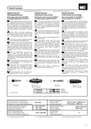
PV female cable coupler PV-KBT3...<br />
PV male cable coupler PV-KST3...<br />
Tipo de conexão Connector system Ø 3mm<br />
T<strong>en</strong>são nominal (V ou kV) Rated voltage<br />
Corr<strong>en</strong>te nominal (A) Rated curr<strong>en</strong>t<br />
Cont<strong>en</strong>t<br />
Safety Instructions ......................................................................2<br />
Tools required ............................................................................3<br />
Connecting cable .......................................................................4<br />
Cable preparation ......................................................................4<br />
Crimp connections ....................................................................4<br />
Crimping ....................................................................................5<br />
— with crimping pliers PV-CZM-16100A ....................................5<br />
— with crimping pliers PV-CZ .....................................................6<br />
<strong>Assembly</strong> ...................................................................................6<br />
Cable routing .............................................................................8<br />
Engagem<strong>en</strong>t ..............................................................................8<br />
1000V DC (IEC)<br />
600V DC (UL)<br />
PV-T3.../S<br />
PV-T3.../S-UR*<br />
20A (IEC: 2,5 – 4mm 2 )<br />
(UL: 14AWG, 12AWG)<br />
30A (IEC: 6mm 2 )<br />
(UL: 10AWG)<br />
T<strong>en</strong>são de teste ou <strong>en</strong>saio Test voltage 6kV (50Hz, 1min.)<br />
Variação da temperature<br />
ambi<strong>en</strong>te<br />
Ambi<strong>en</strong>t temperature range<br />
-40°C...+90°C (IEC)<br />
-40°C...+75°C (UL)<br />
Temperatura limite superior Upper limiting temperature 105°C (IEC)<br />
Grau de pretecção, conectado,<br />
desconectado<br />
Categoria de Sobret<strong>en</strong>são<br />
Grau de poluição<br />
Degree of protection, mated<br />
unmated<br />
Overvoltage category<br />
Pollution degree<br />
IP67<br />
IP2X<br />
CATIII/2<br />
Resistência de contacto dos conectores <strong>Contact</strong> resistance of plug connectors 0,5mΩ<br />
Classe de segurança Safety class II<br />
www.multi-contact.com 1 / 8
Advanced <strong>Contact</strong> Technology<br />
Instruções de segurança Safety Instructions<br />
Os produtos só devem ser montados e instalados por pessoal<br />
qualifi cado e instruído, t<strong>en</strong>do em consideração o cumprim<strong>en</strong>to<br />
das normas e regulam<strong>en</strong>tações de segurança legalm<strong>en</strong>te<br />
aplicáveis.<br />
A <strong>Multi</strong>-<strong>Contact</strong> (MC) exclui qualquer responsabilidade na sequência<br />
do incumprim<strong>en</strong>to destas observâncias.<br />
Utilize ap<strong>en</strong>as os compon<strong>en</strong>tes e ferram<strong>en</strong>tas indicados pela<br />
MC. Respeite os procedim<strong>en</strong>tos de preparação e montagem<br />
aqui descritos, caso contrário a segurança e a observância<br />
dos dados técnicos não estarão asseguradas. Não altere o<br />
produto de n<strong>en</strong>huma forma.<br />
Os conectores de <strong>en</strong>caixe que não são fabricados pela MC e<br />
que podem ser <strong>en</strong>caixados nos produtos da MC, s<strong>en</strong>do, por<br />
vezes, descritos como „compatíveis com os produtos MC“<br />
pelos fabricantes, não estão em conformidade com os requisitos<br />
de uma ligação eléctrica segura e estável a longo prazo,<br />
não dev<strong>en</strong>do ser <strong>en</strong>caixados nos elem<strong>en</strong>tos MC por razões de<br />
segurança. Desta forma, a MC não assume qualquer responsabilidade<br />
pela combinação dos conectores de <strong>en</strong>caixe não<br />
autorizados pela MC com os elem<strong>en</strong>tos MC, bem como pelos<br />
danos daí decorr<strong>en</strong>tes.<br />
Os trabalhos descritos no pres<strong>en</strong>te docum<strong>en</strong>to não<br />
devem ser realizados com as peças ligadas à corr<strong>en</strong>te<br />
eléctrica ou sob t<strong>en</strong>são<br />
A protecção contra choques eléctricos deve ser<br />
fornecida pelo produto fi nal e assegurada pelo utilizador.<br />
Os conectores de <strong>en</strong>caixe não devem ser separados<br />
sob carga. O <strong>en</strong>caixe e separação sob t<strong>en</strong>são<br />
são permitidos.<br />
Os conectores que não podem ser <strong>en</strong>caixados<br />
devem estar protegidos da humidade e sujidade<br />
através de uma tampa (MC3 - artigo n.º 32.0720<br />
para buchas e 32.0721 para conectores). Os conectores<br />
de <strong>en</strong>caixe não devem ser <strong>en</strong>caixados uns nos<br />
outros se estiverem sujos.<br />
A conexão de <strong>en</strong>caixe nunca deve ser exposta a uma<br />
carga de tracção mecânica perman<strong>en</strong>te. O cabo deve<br />
ser fi xado com cintas para cabos.<br />
A MC não recom<strong>en</strong>da a utilização de cabos em PVC<br />
ou de cabos não estanhados do tipo H07RN-F.<br />
Encontrará mais dados técnicos no catálogo de produtos.<br />
2 / 8 www.multi-contact.com<br />
The products may be assembled and installed only by suitably<br />
qualifi ed and trained specialists with due observance of all applicable<br />
safety regulations.<br />
<strong>Multi</strong>-<strong>Contact</strong> (MC) declines any liability in the ev<strong>en</strong>t of failure<br />
to observe these warnings.<br />
Use only the compon<strong>en</strong>ts and tools specifi ed by MC. Do not<br />
deviate from the preparation and assembly procedures described<br />
here, since in this ev<strong>en</strong>t, in the ev<strong>en</strong>t of self-assembly,<br />
no guarantee can be giv<strong>en</strong> as to safety or conformity with the<br />
technical data. Do not modify the product in any way.<br />
Connectors not made by MC which can be mated with MC<br />
elem<strong>en</strong>ts and in some cases are also described as ”MC-compatible”<br />
do not conform to the requirem<strong>en</strong>ts for safe electrical<br />
connection with long-term stability, and for safety reasons<br />
must not be plugged together with MC elem<strong>en</strong>ts. MC can<br />
therefore acce<strong>pt</strong> no liability for damage which occurs as a result<br />
of mating these connectors which lack MC approval with<br />
MC elem<strong>en</strong>ts.<br />
The work described here must not be carried out<br />
on live or load-carrying parts.<br />
Protection from electric shock must be assured by<br />
the <strong>en</strong>d product and its user.<br />
The plug connections must not be disconnected<br />
under load. Plugging and unplugging wh<strong>en</strong> live is<br />
permitted.<br />
Unmated plug connectors must be protected from<br />
moisture and dirt with a sealing cap (MC3 Article<br />
No. 32.0720 sockets and 32.0721 for plugs). The<br />
male and female parts must not be plugged together<br />
wh<strong>en</strong> soiled.<br />
The plug connection must not be subjected to<br />
continuous mechanical t<strong>en</strong>sion. The cable should be<br />
fi xed with cable binders.<br />
MC does not recomm<strong>en</strong>d the use of either PVC cables<br />
or untinned cables of type H07RN-F.<br />
For further technical data please see the product<br />
catalogue.<br />
Explicação dos símbolos Explanation of the symbols<br />
Aviso sobre uma t<strong>en</strong>são eléctrica perigosa<br />
Warning of dangerous voltages<br />
Aviso de um perigo Warning of a hazard area<br />
Alerta ou conselho útil Useful hint or tip
Advanced <strong>Contact</strong> Technology<br />
PV-CZ<br />
UL fi le 343181<br />
Pos.<br />
Locatore<br />
Locator<br />
PV-CZM-16100A<br />
UL File 343181<br />
1<br />
2<br />
2<br />
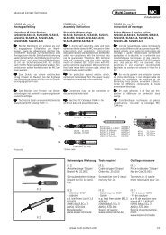
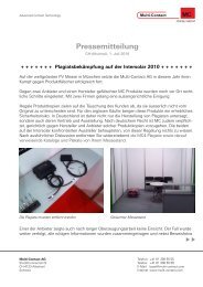
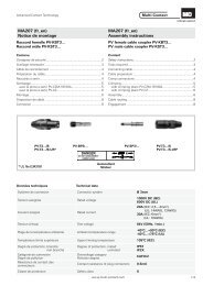
Ferram<strong>en</strong>tas necessárias Tools required<br />
(ill. 1)<br />
Alicate para descravar PV-AZM... incl.<br />
lâmina de descravar incorporada e<br />
chave de f<strong>en</strong>das hexagonal 2,5mm.<br />
Secção de cabo: 1,5 / 2,5 / 4 / 6mm²<br />
Tipo: PV-AZM-1.5/6<br />
Referência N°: 32.6029-156<br />
(ill. 2)<br />
Alicate de cravar PV-CZM-16100A<br />
para secção de cabo de<br />
2,5mm² – 6mm² (14 / 12AWG)<br />
Referência N°: 32.6020-16100A<br />
Aviso:<br />
relativam<strong>en</strong>te à utilização dos alicates<br />
de cravar, ver MA251<br />
(www.multi-contact.com).<br />
o<br />
Alicate de cravar PV-CZ para secção<br />
de cabo de 2,5mm² – 4mm²<br />
Referência N°: 32.6008<br />
(ill. 3)<br />
Aperlho para montagem PV-RWZ3<br />
com 2 cones<br />
Referência N°: 32.6021-16100<br />
1<br />
Spina di trazione<br />
Pull rod<br />
2<br />
Alavanca reset<br />
Reset lever<br />
3<br />
Tipo<br />
Type<br />
Alavanca de activação<br />
Operating lever<br />
Referência<br />
Order No.<br />
Cono<br />
Tapered spindle<br />
Designação Descri<strong>pt</strong>ion<br />
(ill. 1)<br />
Stripping pliers PV-AZM... incl.<br />
built-in wire stripping blade as well as<br />
hexagonal screwdriver A/F 2,5mm.<br />
Cable cross section: 1,5 / 2,5 / 4 / 6mm²<br />
Type: PV-AZM-1.5/6<br />
Order No.: 32.6029-156<br />
(ill. 1)<br />
Crimping pliers PV-CZM-16100A for<br />
cable cross section of<br />
2,5mm² – 6mm² (14 / 12AWG)<br />
Order No.: 32.6020-16100A<br />
Notes:<br />
to the operation of the crimping<br />
pliers, see MA251<br />
(www.multi-contact.com)<br />
or<br />
Crimping pliers PV-CZ for cable cross<br />
section of 2,5mm² and 4mm²<br />
Order No.: 32.6008<br />
(ill. 3)<br />
<strong>Assembly</strong> device PV-RWZ3 incl. 2<br />
tapered spindles<br />
Order No.: 32.6021-16100<br />
1 + 2 + 3 PV-RWZ3 32.6050 Aparelho para montagem com 2 cones <strong>Assembly</strong> device incl. 2 tapered spindles<br />
Partes avulsas Individual parts<br />
1 PV-R-RWZ3 32.6051 Aparelho para montagem <strong>Assembly</strong> device<br />
2 PV-KO3 I+II 32.6052 Cone para isolam<strong>en</strong>tos tamanho I + II Tapered spindle for insulators size I + II<br />
3 PV-KO3 III 32.6053 Cone para isolam<strong>en</strong>tos tamanho III Tapered spindle for insulators size III<br />
www.multi-contact.com 3 / 8<br />
3
Advanced <strong>Contact</strong> Technology<br />
Tab. 1<br />
Tamanho<br />
Size<br />
Tab. 2<br />
Tipo<br />
Type<br />
L<br />
G<br />
Comprim<strong>en</strong>to L (mm)<br />
L<strong>en</strong>gth L (mm)<br />
PV-BP3/4 6 – 7,5<br />
PV-SP3/4 6 – 7,5<br />
PV-BP3/6 8,5 – 9,5<br />
PV-SP3/6 8,5 – 9,5<br />
H<br />
G (mm) H (mm)<br />
I 2,8 3,2 – 4,8<br />
II 4 4,9 – 7,1<br />
III 6 6,5 – 9<br />
4 / 8 www.multi-contact.com<br />
4<br />
5<br />
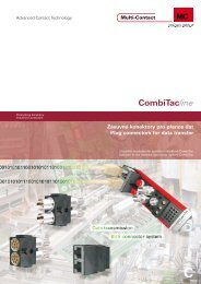
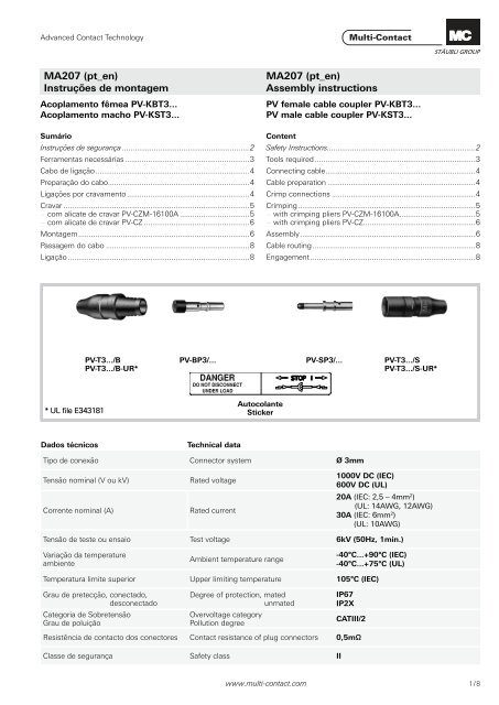
Cabo de ligação Connecting cable<br />
(ill. 4 / Tab. 1)<br />
Certifi que-se de que existe um vedante<br />
seguro <strong>en</strong>tre o acoplam<strong>en</strong>to macho<br />
PV e o cabo:<br />
É possível utilizar cabos multifi lares<br />
com dim<strong>en</strong>sões AWG.<br />
De acordo com a tabela 1 e a fi gura<br />
4, certifi que-se de que o diâmetro do<br />
casquilho G está correcto para o cabo.<br />
At<strong>en</strong>ção:<br />
Ao seleccionar cabos de ligação<br />
com um isolam<strong>en</strong>to duplo,<br />
esteja at<strong>en</strong>to a que haja sufi ci<strong>en</strong>te<br />
aderência <strong>en</strong>tre as camadas<br />
isoladoras, de modo a que não<br />
se possam separar <strong>en</strong>tre si e do<br />
condutor.<br />
(ill. 4 / Tab. 1)<br />
Ensure that there is a tight seal betwe<strong>en</strong><br />
the male PV coupler and the<br />
cable:<br />
It is possible to use multiple-wire<br />
cables in AWG dim<strong>en</strong>sions.<br />
Check on the basis of illustration 4<br />
and table 1 that the lead-through G<br />
has the correct diameter for the cable.<br />
Att<strong>en</strong>tion:<br />
Wh<strong>en</strong> choosing double-insulated<br />
connecting leads, take care that<br />
there is suffi ci<strong>en</strong>t adhesion betwe<strong>en</strong><br />
the layers of insulation.<br />
If this is not the case, the layers<br />
can slide over each other or shift<br />
on the conductor.<br />
Preparação do cabo Cable preparation<br />
Os cabos com construção classe 5 ou<br />
6 podem ser ligados.<br />
At<strong>en</strong>ção:<br />
Não utilize condutores oxidados<br />
e não revestidos. Condutores estanhados<br />
têm vantag<strong>en</strong>s. Todos<br />
os cabos solares MC possuem<br />
condutores estanhados de elevada<br />
qualidade.<br />
(ill. 5)<br />
Descarnar o cabo. Comprim<strong>en</strong>to de<br />
acordo com a Tab. 2.<br />
At<strong>en</strong>ção:<br />
Ter cuidado para não cortar os<br />
fi os.<br />
Aviso:<br />
Para saber como utilizar os alicates<br />
de descravar PV-AZM... e substituição<br />
dos conjuntos de lâminas, ver as<br />
instruções de utilização MA267 sur<br />
www.multi-contact.com<br />
For TÜV certifi ed assembly cables<br />
with a strand construction of classes 5<br />
and 6 must be connected.<br />
Att<strong>en</strong>tion:<br />
Use no uncoated or already oxidised<br />
conductors. It is advantage<br />
to use tinned conductors. All MC<br />
solar cables have high-quality,<br />
tinned conductors.<br />
(ill. 5)<br />
Strip cable insulation.<br />
L<strong>en</strong>gth according to Tab. 2.<br />
Att<strong>en</strong>tion:<br />
Do not cut individual strands at<br />
stripping.<br />
Note:<br />
For directions on the use of stripping<br />
pliers PV-AZM... and changing<br />
blade sets, see operating instruction<br />
MA267 at www.multi-contact.com<br />
Ligações por cravam<strong>en</strong>to Crimp connections<br />
Para ligar os condutores aos casquilhos<br />
de cravar dos acoplam<strong>en</strong>tos<br />
PV recom<strong>en</strong>damos a utilização das<br />
ferram<strong>en</strong>tas de cravar indicadas. Os<br />
casquilhos de cravar são concebidos<br />
para condutores fl exíveis (classes 5<br />
e 6 de acordo com as normas IEC<br />
60228, DIN VDE 0295), com secções<br />
de condutor de 2,5mm² – 10mm².<br />
For connecting the conductors to the<br />
crimp sleeves of the PV couplers, we<br />
recomm<strong>en</strong>d using the stated crimping<br />
tools. The crimping sleeves are designed<br />
for fl exible wires (classes 5 and<br />
6 according to IEC 60228, DIN VDE<br />
0295) with conductor cross-sections<br />
of 2,5mm² to 10mm².
Advanced <strong>Contact</strong> Technology<br />
S<br />
max. 1 mm<br />
6<br />
7<br />
8<br />
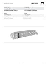
Cravar Crimping<br />
com alicate de cravar PV-CZM-<br />
16100A<br />
para secção do cabo de 2,5mm²,<br />
4mm² e 6mm²<br />
Esta ferram<strong>en</strong>ta de cravar está equipada<br />
com <strong>en</strong>caixes de cravar intercambiáveis<br />
para as seguintes gamas de<br />
secção de condutor:<br />
1) 2,5 / 4 / 6mm 2 (14 / 12 / 10AWG)<br />
2) 4 / 10mm 2 (12AWG)<br />
Na seguinte descrição do processo de<br />
cravar utilizaram-se fi guras da gama<br />
de secção (1). O procedim<strong>en</strong>to de<br />
cravar para a gama de secção (2) é<br />
idêntico.<br />
Para obter mais dicas sobre a utilização<br />
da ferram<strong>en</strong>ta de cravar e a<br />
substituição dos <strong>en</strong>caixes de cravar e<br />
dos localizadores adequados, ver as<br />
instruções de utilização MA251 em<br />
www.multi-contact.com<br />
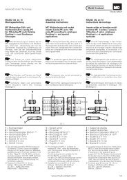
(ill. 6)<br />
Coloque a parte de metal do acoplam<strong>en</strong>to<br />
fêmea ou acoplam<strong>en</strong>to macho<br />
na guia para a secção adequada. Introduza<br />
o cabo no casquilho de cravar<br />
até onde for possível e fi xe-o.<br />
(ill. 7)<br />
At<strong>en</strong>ção:<br />
Todos os fi os condutores devem<br />
ser introduzidos no orifício S, perman<strong>en</strong>c<strong>en</strong>do<br />
visíveis e respeitando<br />
a dim<strong>en</strong>são máxima de 1mm.<br />
Feche totalm<strong>en</strong>te a ferram<strong>en</strong>ta de<br />
cravar.<br />
(ill. 8)<br />
Verifi que visualm<strong>en</strong>te a cravação.<br />
with crimping pliers PV-CZM-<br />
16100A<br />
for cable cross section 2,5mm²,<br />
4mm² and 6mm²<br />
This crimping tool is equipped with interchangeable<br />
crimping inserts for the<br />
following wire cross-section ranges:<br />
1) 2,5 / 4 / 6mm 2 (14 / 12 / 10AWG)<br />
2) 4 / 10mm 2 (12AWG)<br />
In the following descri<strong>pt</strong>ion of the<br />
crimping process, illustrations from<br />
cross section range (1) have be<strong>en</strong><br />
used. The crimping procedure for<br />
cross-section range (2) is id<strong>en</strong>tical.<br />
For further hints on the operation of<br />
the crimping tool and for changing the<br />
crimping inserts and the appropriate<br />
locators, please see operating instruction<br />
MA251 at www.multi-contact.<br />
com<br />
(ill. 6)<br />
Place the metal part of the female<br />
or male coupler in the guide for the<br />
appropriate cross section. Insert the<br />
wire into the crimping sleeve as far as<br />
it will go. Hold the wire in place in the<br />
sleeve.<br />
(ill. 7)<br />
Att<strong>en</strong>tion:<br />
All strands of the wires must be<br />
correctly inserted into the borehole<br />
and visible in sight hole S.<br />
The max. distance of 1mm must<br />
not be exceeded.<br />
Completely close the crimping tool.<br />
(ill. 8)<br />
Visually check the crimp.<br />
www.multi-contact.com 5 / 8
Advanced <strong>Contact</strong> Technology<br />
S<br />
max. 1 mm<br />
Industriealkohol<br />
Industrial alcohol<br />
alcool industriel<br />
6 / 8 www.multi-contact.com<br />
9<br />
9<br />
10<br />
11<br />
12<br />
com alicate de cravar PV-CZ<br />
para secção do cabo 2,5mm² e<br />
4mm²<br />
(ill. 9)<br />
Coloque a parte de metal do acoplam<strong>en</strong>to<br />
fêmea ou acoplam<strong>en</strong>to macho<br />
na guia para a secção adequada. Introduza<br />
o cabo no casquilho de cravar<br />
até onde for possível e fi xe-o.<br />
(ill. 10)<br />
At<strong>en</strong>ção:<br />
Todos os fi os condutores devem<br />
ser introduzidos no orifício S, perman<strong>en</strong>c<strong>en</strong>do<br />
visíveis e respeitando<br />
a dim<strong>en</strong>são máxima de 1mm.<br />
Feche totalm<strong>en</strong>te a ferram<strong>en</strong>ta de<br />
cravar.<br />
(ill. 11)<br />
Verifi que visualm<strong>en</strong>te a cravação.<br />
with crimping pliers PV-CZ<br />
for cable cross section 2,5mm²<br />
and 4mm²<br />
(ill. 9)<br />
Place the metal part of the female<br />
or male coupler in the guide for the<br />
appropriate cross section. Insert the<br />
wire into the crimping sleeve as far as<br />
it will go. Hold the wire in place in the<br />
sleeve.<br />
(ill. 10)<br />
Att<strong>en</strong>tion:<br />
All strands of the wires must be<br />
correctly inserted into the borehole<br />
and visible in sight hole S.<br />
The max. distance of 1mm must<br />
not be exceeded.<br />
Completely close the crimping tool.<br />
(ill. 11)<br />
Visually check the crimp.<br />
Montagem <strong>Assembly</strong><br />
(ill. 12)<br />
Aviso:<br />
Para facilitar o operação, mergulhar<br />
préviam<strong>en</strong>te a saída de cabo dos<br />
corpos isoladores em álcool industrial<br />
antes de inserir os contactos.<br />
(ill. 12)<br />
Note:<br />
You can facilitate the assembly procedure<br />
by immersing the connector<br />
insulators in industrial alcohol before<br />
inserting the contacts.
Advanced <strong>Contact</strong> Technology<br />
PV-KO3 I+II<br />
40mm min.<br />
Ranhuras / Grooves<br />
13<br />
14<br />
15<br />
16<br />
17<br />
18<br />
19<br />
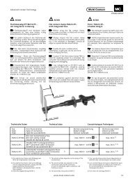
(ill. 13)<br />
Segure na ferram<strong>en</strong>ta de montagem<br />
pela haste dianteira.<br />
Pressione simultaneam<strong>en</strong>te a alavanca<br />
de reiniciar R na direcção da seta<br />
com o polegar e prima na totalidade a<br />
haste de tracção Z com a outra mão.<br />
(ill. 14)<br />
Selecionar o cone:<br />
• PV-KO3 I+II para isolam<strong>en</strong>tos de<br />
jacks e de fi chas de tamanho I e II<br />
• PV-KO3 III para isolam<strong>en</strong>tos de jacks<br />
e de fi chas de tamanho III<br />
Empurrar o cone por trás através do<br />
isolam<strong>en</strong>to de jacks e da tomada até<br />
o pino de tracção sair cerca de 40mm<br />
para fora do isolam<strong>en</strong>to de jacks e/ou<br />
da tomada.<br />
(ill. 15)<br />
Introduza o acoplam<strong>en</strong>to macho ou<br />
o acoplam<strong>en</strong>to fêmea com o cabo<br />
<strong>en</strong>gastado no eixo cónico.<br />
(ill. 16)<br />
Introduza o eixo cónico na ferram<strong>en</strong>ta<br />
de montagem e ligue-o ao fi xador<br />
do eixo <strong>en</strong>quanto segura na haste de<br />
tracção.<br />
(ill. 17)<br />
Ao activar a alavanca da ferram<strong>en</strong>ta,<br />
retire o eixo cónico através da <strong>en</strong>trada<br />
da ferram<strong>en</strong>ta <strong>en</strong>quanto segura no<br />
cabo, exerc<strong>en</strong>do uma ligeira pressão<br />
no eixo até o acoplam<strong>en</strong>to macho<br />
ou acoplam<strong>en</strong>to fêmea <strong>en</strong>caixar no<br />
isolam<strong>en</strong>to. Retire totalm<strong>en</strong>te o eixo<br />
cónico do isolam<strong>en</strong>to.<br />
(ill. 18)<br />
Retire o acoplam<strong>en</strong>to macho ou<br />
acoplam<strong>en</strong>to fêmea da ferram<strong>en</strong>ta de<br />
montagem.<br />
(ill. 19)<br />
Para empurrar a haste de tracção<br />
Z até atingir a sua posição inicial,<br />
remova o eixo cónico K da ferram<strong>en</strong>ta<br />
de montagem.<br />
(ill. 13)<br />
Hold the assembly tool by the pull-in<br />
tube.<br />
Press the return lever R with the<br />
thumb in the direction of the arrow<br />
and at the same time press in the<br />
puller rod Z to the limit with the other<br />
hand.<br />
(ill. 14)<br />
Select the appropriate tapered spindle:<br />
• PV-KO3 I+II for male and female<br />
coupler insulators of sizes I and II<br />
• PV-KO3 III for male and female coupler<br />
insulators of size III<br />
Push the tapered spindle from behind<br />
into the male or female insulator until<br />
the puller rod protrudes from the male<br />
or female insulator by approx. 40mm.<br />
(ill. 15)<br />
Insert the male or female coupler<br />
with crimped-on lead into the tapered<br />
spindle.<br />
(ill. 16)<br />
Insert the tapered spindle into the<br />
assembly tool and attach it to the<br />
spindle holder. During this operation<br />
hold the puller rod in position.<br />
(ill. 17)<br />
Actuate the handle of the tool several<br />
times. This pulls the tapered spindle<br />
through the infeed op<strong>en</strong>ing of the<br />
tool. Apply g<strong>en</strong>tle pressure to keep<br />
the lead in the spindle until the male<br />
or female coupler part <strong>en</strong>gages in<br />
the insulator. Pull the tapered spindle<br />
completely out of the insulator.<br />
(ill. 18)<br />
Withdraw the male or female coupler<br />
from the assembly tool.<br />
(ill. 19)<br />
Return the puller rod Z to its starting<br />
position.<br />
Remove the tapered spindle K from<br />
the assembly tool.<br />
www.multi-contact.com 7 / 8
Advanced <strong>Contact</strong> Technology<br />
20<br />
21<br />
(ill. 20)<br />
Puxando ligeiram<strong>en</strong>te o cabo,<br />
certifi que-se de que a bucha está bem<br />
presa na peça de metal.<br />
Se as peças montadas estiverem<br />
alinhadas com o lado da fr<strong>en</strong>te do silam<strong>en</strong>to,<br />
isto signifi ca que a montagem<br />
está correcta.<br />
(ill. 21)<br />
Coloque o autocolante incluido „DAN-<br />
GER – DO NOT DISCONNECT UNDER<br />
LOAD“ o mais próximo possível do<br />
ligador macho do cabo.<br />
Passagem do cabo Cable routing<br />
Recorra às especifi cações do fabricante<br />
do cabo para o raio de curvatura<br />
mínimo.<br />
(ill. 20)<br />
Pull g<strong>en</strong>tly on the lead to check that<br />
the sleeve is correctly locked in place<br />
on the metal part.<br />
If it is correcly located, the fi tted parts<br />
must be fl ush with the front face of<br />
the insulator.<br />
(ill. 21)<br />
Affi x the supplied sticker “DANGER<br />
– DO NOT DISCONNECT UNDER<br />
LOAD” in the vicinity of the PV coupler.<br />
Refer to cable manufactures specifi cation<br />
for minimum b<strong>en</strong>ding radius.<br />
alterations<br />
to Subject /<br />
Ligação Engagem<strong>en</strong>t<br />
alterações à<br />
Certifi que-se de que as peças de aco- Check that the coupler parts are fully<br />
plam<strong>en</strong>to estão bem presas.<br />
<strong>en</strong>gaged.<br />
Sujeito – Communications Global , l index 02.2012, – <strong>MA207</strong> –<br />
Fabricante/Producer:<br />
Switzerland<br />
<strong>Multi</strong>-<strong>Contact</strong> AG<br />
AG,<br />
Stockbrunn<strong>en</strong>rain 8<br />
CH – 4123 Allschwil<br />
Tel. +41/61/306 55 55<br />
Fax +41/61/306 55 56<br />
<strong>Multi</strong>-<strong>Contact</strong><br />
mail basel@multi-contact.com<br />
by<br />
www.multi-contact.com ©