Create successful ePaper yourself
Turn your PDF publications into a flip-book with our unique Google optimized e-Paper software.
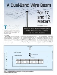
A 2-<strong>Meter</strong> <strong>Vertical</strong> <strong>Dipole</strong> <strong>Array</strong><br />
Build this 2 or 4-Element VHF repeater antenna with up to 9.7 dBi<br />
gain and 18° <strong>Vertical</strong> Beamwidth.<br />
M<br />
ost commercial 2-meter repeater antennas with gain fall into two categories:<br />
collinear arrays and stacked element arrays, with gains ranging from 3 to 9 dB 1 .<br />
The higher gain antennas have a lower vertical beamwidth. For example, a<br />
typical 4-element exposed dipole offset array with 9 dB gain has a vertical beamwidth of<br />
16°. This is the angle above and below the horizon at which the signal is half the<br />
strength (-3 dB) of the signal at the horizon. In general, high gain antennas work best<br />
from low level sites, or high elevation sites far away from the targeted area. For high<br />
sites near the target area, a lower gain antenna with a higher vertical beamwidth is used.<br />
This prevents the signal from passing over the target area. 2<br />
Exposed dipole arrays fall into the stacked element array category. They resemble<br />
folded dipoles and their construction often requires tube bending, welding, or special<br />
brackets. Coaxial collinear arrays (made from coax) are easier to build but do not break<br />
down into convenient lengths for transporting. <strong>Vertical</strong> dipole arrays built from individual<br />
and unconnected center-fed dipoles are among the simplest to construct but can be<br />
difficult to feed. Unless each feedline is routed a significant distance away from the<br />
antenna at a 90° angle, feedline coupling will distort the radiation pattern.<br />
With these ideas in mind, I began modeling antennas in search of an easy to build, all<br />
metal, vertical dipole array. The antenna that emerged from these modeling sessions<br />
consists of four vertical dipoles, each centered on a 60 inch vertical section. While the<br />
array can be built using a variety of methods and materials, a copper pipe version is<br />
presented here. The array is offset 3 , with all elements and maximum gain on the same<br />
side of the mast. In addition to 9.7 dBi gain, each dipole is 50Ω, allowing the phasing<br />
harness to be built from readily available 75Ω coax. The phasing harness sections are<br />
strapped to each dipole, minimizing feedline coupling and pattern distortion. For high<br />
elevation sites near the target area, one-half of the array can be used to provide less<br />
gain (6.85 dBi) and a higher vertical beamwidth (36°).<br />
Antenna Construction<br />
The array can be built using four identical dipoles. However, the length and feedpoint<br />
impedance of each dipole is influenced by its location in the array. Inner sections are<br />
affected by the outer section on both sides and hence differ in impedance from the outer<br />
sections, which are affected on only one side. In order for the phasing harness to work<br />
correctly, each antenna in the array should be as close as possible to 50Ω at the<br />
resonant frequency 4 . For this reason, each dipole in the array has been optimized. (See<br />
individual SWR plots, attachment 2 of 9).<br />
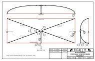
The array is built entirely from ½ inch copper pipe and fittings and is 20 feet tall.<br />
However, due to the weight of copper pipe it must be supported (or hung) from a tower<br />
or fastened to a non-metallic mast. To construct the 4-element array you will need 35<br />
feet of ½ inch type L copper pipe, eight ½ inch copper tees, ten ½ inch copper caps,<br />
A 2-<strong>Meter</strong> <strong>Vertical</strong> <strong>Dipole</strong> <strong>Array</strong>, <strong>KG4JJH</strong> Page 1 of 6
three ½ inch unions, and 12 inches of ¼ inch PVC pipe (0.540 inch OD). The caps are<br />
optional and are for the prevention of mud dauber nests. If installed, drill a 1/8 inch hole<br />
in the bottom caps for moisture drainage. If they are not installed, increase the pipe<br />
lengths accordingly. Cut the PVC pipe into four, three inch pieces, to make the feedpoint<br />
isolators for each dipole.<br />
One-half inch type L copper pipe has an actual OD of 5/8 inch and an ID of 0.545<br />
inches. Copper pipe fittings now come in normal and pre-soldered 5 varieties and the<br />
dimensions can vary. It is more accurate to cut the pipe slightly longer than needed,<br />
sweat the joint, and then trim to length with a tubing cutter and a file.<br />
Centerline dimensions as well as cut pipe lengths (for pre-soldered fittings) are included<br />
on Drawing 1. Use 6-32 x 7/8 inch stainless steel pan head screws, washers, and<br />
locknuts for all feedpoint hardware. Drill the feedpoint screw holes using a drill press and<br />
then deburr the inside of the pipe with a round file. Next, insert the three inch length of<br />
PVC, align and tape the feedpoint assembly together, and then drill the PVC. This allows<br />
the PVC to be easily removed for sweating the pipe joints and prevents it from melting.<br />
Flag terminals are soldered to the coax and attached to the feedpoint screws. The<br />
exposed coax ends are sealed with Coax-Seal 6 and the harness is secured to the pipe<br />
with cable ties. Male UHF connectors are soldered to the other ends of the coax.<br />
Each 60 inch dipole section is secured to the mast with 10-24 x 1-¼ inch stainless steel<br />
screws and stop nuts. After drilling 3/16 inch holes at each end (see Drawing 1), match<br />
drill corresponding holes on the assembled mast sections. Insert a screw in each mast<br />
from the inside and secure it on the outside with a stop nut. Depending on where the<br />
mast holes fall this may require taping a string on the end of the screw and fishing it<br />
through the mast hole. Each dipole can now be fastened to the mast by placing it over<br />
the mast screws and secured with a stop nut.<br />
Dimensional Changes<br />
A larger diameter for the 60 inch vertical section is possible as long as the horizontal<br />
distance between the vertical section OD and the dipole OD is maintained. The ½ inch<br />
copper array centerline dimension between the vertical section and the dipole is 9<br />
inches. This distance between outside diameters (for ½ inch copper pipe) is 8-3/8 inches<br />
(9 inches between centerlines minus 5/16 inch on each pipe). If, for example, the 60 inch<br />
vertical section is increased to 1-1/2 inches OD, you must maintain the 8-3/8 inches<br />
between outside diameters. This will increase the centerline dimension to 9-7/16 inches.<br />
The feedpoint dimension may also have to be moved slightly to obtain 50Ω at<br />
resonance. An aluminum clamp-on array, shown on Drawing 4, illustrates the use of<br />
different materials and construction techniques. The dipoles are made of 1-3/8 inch OD<br />
aluminum tubing and are clamped to a metallic 1-1/2 inch OD mast. I encourage the<br />
reader to use an antenna modeling program to model any changes before construction<br />
Phasing Harness<br />
The 4-element array phasing harness is based on feeding four 50Ω antennas from one<br />
50Ω feedline. Likewise, the 2-element array uses two 50Ω antennas fed from one 50Ω<br />
feedline. Coax connectors and tees are used to aid in a faster setup. If your antenna<br />
installation is permanent, you may want to solder and weatherproof the coax junctions to<br />
minimize losses. Figures 1 and 2 show the 4-element and 2-element harnesses,<br />
respectively, with cable lengths and impedances at each point. Optimum coax lengths<br />
are necessary to prevent from having too much cable to strap to the antenna. When<br />
A 2-<strong>Meter</strong> <strong>Vertical</strong> <strong>Dipole</strong> <strong>Array</strong>, <strong>KG4JJH</strong> Page 2 of 6
cutting cable lengths, remember that the velocity factor applies only to that portion of<br />
coax where the center conductor insulation is still in place. The math involved for<br />
calculating coax impedance and length is as follows:<br />
Lambda (λ) is the physical wavelength of coax and is defined as:<br />
λ = (Electrical Wavelength at F O ) X (Velocity Factor of the Coax)<br />
Equation 1: ¼λ = (2952/F O ) X (VF)<br />
Where<br />
F O = Design Frequency = SQRT (F INPUT X F OUTPUT )<br />
For this TNSG 7 repeater, the frequencies are<br />
F INPUT = 143.225 MHz<br />
F OUTPUT = 149.800 MHz<br />
F O = SQRT (143.225 X 149.800) = 146.475, or 146.5 MHz<br />
Equation 2: Z O = SQRT (Z IN X Z OUT )<br />
Where<br />
Z O = Transforming coax<br />
Z IN = Input impedance<br />
Z OUT = Output impedance<br />
Each antenna is 50Ω at the operating frequency. Because we are combining four<br />
antennas in parallel at the connection point, the impedance of the connecting cables A,<br />
B, C, and D must be 100Ω at the point of connection. Two 100Ω impedances connected<br />
in parallel produce an impedance of 50Ω. A quarter wavelength (and odd multiple) of<br />
cable that provides the proper characteristic impedance can transform the 50Ω<br />
impedance of each antenna to 100Ω at the connection point 8 The required characteristic<br />
impedance of cables A, B, C, and D can be found from the formula in Equation 2. In this<br />
application, the calculation is shown as:<br />
Cables A, B, C, and D:<br />
Z O = SQRT (50 X 100) = 70.7, 75Ω coax<br />
RG-11A/U, 75Ω, 0.66 VF (Wireman 121)<br />
VF was verified using an MFJ-259B: 0.6638<br />
<strong>Vertical</strong> distance between <strong>Dipole</strong> 1 - 2, and 3 - 4: 60 inches<br />
Minimum length needed for each cable: 60/2 = 30 inches<br />
Length needed for each cable (strapped to antenna): 29+8+3 = 40 inches<br />
F O = 146.5 MHz<br />
¼λ = (2952/F O ) X (VF) = (2952/146.5) X (0.6638) = 13.376 inches<br />
Odd multiples of ¼λ: 1 X ¼ λ = 13.376 inches (not long enough)<br />
3 X ¼ λ = 40.128, or 40-1/8 inches<br />
Cables E and F:<br />
The math for cables E and F is the same except for the distances involved.<br />
Z O = SQRT (50 X 100) = 70.7, 75Ω coax<br />
RG-11A/U, 75Ω, 0.66 VF (Wireman 121)<br />
Distance between Tees 1 and 2: 120 inches<br />
Minimum length needed for each cable: 120/2 = 60 inches<br />
F O = 146.5 MHz<br />
A 2-<strong>Meter</strong> <strong>Vertical</strong> <strong>Dipole</strong> <strong>Array</strong>, <strong>KG4JJH</strong> Page 3 of 6
¼λ = (2952/F O ) X (VF) = (2952/146.5) X (0.6638) = 13.376 inches<br />
Odd multiples of ¼λ: 1 X ¼ λ = 13.376 inches (not long enough)<br />
3 X ¼ λ = 40.128 inches (not long enough)<br />
5 X ¼ λ = 66.880, or 66-7/8 inches<br />
The phasing harness loss at 150 MHz is calculated to be 0.67 dB. Additional loss from<br />
50 feet of RG-8 (Wireman CQ102) is 0.79 dB, for a total cable loss of 1.46 dB. The total<br />
cable loss for the 2-element array is 0.96 dB.<br />
Antenna Coverage and Testing<br />
Initial testing was performed with the 2-element array in my back yard. Using a GPS,<br />
latitude, longitude, and elevation data were fed into a HAAT 9 calculator to obtain a value<br />
of 33 feet. This “Height Above Average Terrain” value represents an average of the<br />
terrain elevations within 10 miles of the transmitter site, and provides a single value on<br />
which general coverage calculations and regulatory requirements may be based. Using<br />
5 watts, comparisons with a J-Pole at the same elevation indicated that the 2-element<br />
array was a major improvement for distant repeater access.<br />
Subsequent testing was done with the assistance of NG4T, Communications and<br />
Electronics Officer for the Third Alvin C. York Regiment of the Tennessee State Guard.<br />
For this location, the 4-element array’s HAAT was calculated to be 40 feet. Antenna<br />
coverage was tested using a Motorola Micor at 40 watts and a six cavity mobile<br />
duplexer. Using 5 watt HT’s, communication ranges of up to 15 miles were established<br />
in residential areas with rolling hills and considerable ground clutter.<br />
Portability & Assembly<br />
The array was built with portability in mind. Each 60 inch section mechanically attaches<br />
to the next with a copper union and the array is clamped to a 44.5 foot fiberglass mast.<br />
This sectional surplus mast was used by the military for camouflage screening. Stainless<br />
steel screws (10-24 x 1-¼ inch and stop nuts) installed from inside the top 6 mast<br />
sections secures the array to the mast. The array is offset about 10 inches down from<br />
the top guy ring to prevent interference with the guy lines. The 4-element array weighs<br />
13 pounds (including phasing harness) and breaks down into a 1 by 5 foot bag. A<br />
second bag contains the harness, cable ties, Coax-Seal®, stakes, hammer, wrench, and<br />
guy lines. A third bag holds the 12 fiberglass mast sections.<br />
When assembling the array, ensure that all dipole feedpoints are oriented in the same<br />
direction (i.e. all on the bottom or all on the top), and are lined up vertically. Failure to do<br />
this will result in a less than optimal radiation pattern. I recommend labeling each dipole<br />
and its associated position on the mast. Setup is accomplished with two to three people<br />
in under two hours. Install a tilt base vertically in the ground at the desired location. Lay<br />
the mast sections down with the large ends pointed toward the base and the screw<br />
sections at the top. Plug the mast sections together, adding guy rings at the top of the<br />
3 rd , 6 th , and 12 th mast sections. Attach each antenna section to the mast using 10-24<br />
stainless steel stop nuts and connect the sections. Assemble the coax tee connections<br />
and feedline and secure to the mast using cable ties. Waterproof the coax tee<br />
connections using Coax Seal®. Next, attach the appropriate length guy lines to each guy<br />
ring using snap clips. Measure a 23 foot radius from the base of the mast and install<br />
three stakes, 120° apart, with one stake in the direction of the prevailing wind. Attach two<br />
sets of three guy lines to the closer two stakes and pull/push the mast upright. Finally,<br />
A 2-<strong>Meter</strong> <strong>Vertical</strong> <strong>Dipole</strong> <strong>Array</strong>, <strong>KG4JJH</strong> Page 4 of 6
secure the third set of guy lines to the last stake and adjust the guy line tension as<br />
needed to obtain a vertical mast.<br />
Antenna Gain Comparison<br />
The EZNEC 10 modeling program displays gain in dBi, whether in free space or over<br />
ground. In an effort to present a fair comparison and to avoid confusion over gain<br />
figures, several vertically polarized antennas were modeled and compared to the 2 and<br />
4-Element <strong>Vertical</strong> <strong>Dipole</strong> <strong>Array</strong>. The reference antenna is a 2-meter vertical dipole<br />
made of 5/8 inch OD copper, fed in the middle, and resonant at 146.5 MHz. The<br />
modeled statistics for free space and 45 foot elevations (over average ground) are<br />
summed up in Table 1.<br />
2-<strong>Meter</strong><br />
<strong>Vertical</strong>ly Polarized<br />
Antenna<br />
Gain<br />
dBi<br />
Table 1<br />
Elevation: Free Space<br />
Gain over<br />
<strong>Vertical</strong> <strong>Dipole</strong><br />
dBi (dBd)<br />
<strong>Vertical</strong><br />
Beamwidth<br />
°<br />
Gain<br />
dBi<br />
Elevation: 45 ft.<br />
Gain over<br />
<strong>Vertical</strong> <strong>Dipole</strong><br />
dBi<br />
<strong>Vertical</strong> <strong>Dipole</strong> Reference 2.15 - 78.0 6.99 -<br />
Collinear J-Pole 4.99 2.84 39.5 9.45 2.46<br />
<strong>Vertical</strong> Moxon Rectangle 6.00 3.85 79.4 10.80 3.81<br />
2-El <strong>Vertical</strong> <strong>Dipole</strong> <strong>Array</strong> 6.85 4.70 35.4 11.18 4.19<br />
3-El <strong>Vertical</strong> Yagi 8.50 6.35 61.0 13.27 6.28<br />
4-El <strong>Vertical</strong> <strong>Dipole</strong> <strong>Array</strong> 9.71 7.56 17.2 13.77 6.78<br />
Transportable TNSG Repeater<br />
With the recent addition of TEMA 11 responsibilities to the state guard, regiments are<br />
being asked to provide emergency communications during emergency and disaster<br />
situations. To assist the Tennessee State Guard in accomplishing its mission, I have<br />
donated this antenna and mast to the Third Alvin C. York Regiment for use as part of a<br />
transportable Tennessee State Guard repeater system.<br />
Wrapping Up<br />
Elevation is the single most important factor when choosing a repeater antenna site and<br />
it can be a challenging process to find the optimum location for a given target area.<br />
Attempting this with a portable system is even harder as the location will change from<br />
one setup to the next. The 2 and 4-Element <strong>Vertical</strong> <strong>Dipole</strong> <strong>Array</strong>s presented here<br />
provide some flexibility for installations in different situations. The 2-element array would<br />
be the best choice for high elevation sites near the target area. The 4-element array<br />
should be used for high elevation sites far away from the target area, or low elevations<br />
sites near the target area. Portability combined with respectable gain has validated the 2<br />
and 4-Element <strong>Vertical</strong> <strong>Dipole</strong> <strong>Array</strong> as an effective VHF antenna for emergency or<br />
general 2-meter repeater use.<br />
Allen Baker, <strong>KG4JJH</strong><br />
211 Brochardt Blvd.<br />
Knoxville, TN 37934<br />
865-675-1915<br />
kg4jjh@arrl.net<br />
A 2-<strong>Meter</strong> <strong>Vertical</strong> <strong>Dipole</strong> <strong>Array</strong>, <strong>KG4JJH</strong> Page 5 of 6
References<br />
1 The general practice among commercial antenna manufacturers is to express gain in<br />
dB (or dBd), where 2.15 dBi (Isotropic Gain) = 0 dBd (<strong>Dipole</strong> Gain).<br />
2 Paul Shinn, KAF8333, What They Never Told You About Repeater Antennas, GMRS<br />
Web Magazine; http://www.popularwireless.com/gmrsrpt051599.html<br />
3 A 7 dBi omni version is possible, but the elevation pattern is somewhat distorted.<br />
4 L.B. Cebik, W4RNL, E-mail correspondence.<br />
5 EZ-Sweat pre-soldered copper fittings, Watts Water Technologies;<br />
http://www.wattsreg.com/pro/whatsnew/whatsnew_ezsweat.htm<br />
6 Coax-Seal, http://www.coaxseal.com/<br />
7 The Amateur 2-meter band plan is 144-148 MHz. 143-150 MHz is for a Tennessee<br />
State Guard (TNSG) repeater; http://tsg3.us<br />
8 Harold Kinley, Antenna Phasing 101, Mobile Radio Technology, September 1, 2004;<br />
http://www.findarticles.com/p/articles/mi_m0HEP/is_9_22/ai_n6196620<br />
9 Stan Horzepa, WA1LOU, The Return of the HAAT Calculator, ARRL Web, January 6,<br />
2006, http://www.arrl.org/news/features/2006/01/06/1/<br />
10 EZNEC Antenna Software, Roy Lewallen, W7EL; http://www.eznec.com/<br />
11 TEMA, Tennessee Emergency Management Agency<br />
A 2-<strong>Meter</strong> <strong>Vertical</strong> <strong>Dipole</strong> <strong>Array</strong>, <strong>KG4JJH</strong> Page 6 of 6
ANTENNA-1<br />
50<br />
A = 40-1/8"<br />
60"<br />
ANTENNA-2<br />
100<br />
COAX<br />
TEE<br />
100<br />
1<br />
50<br />
E = 66-7/8"<br />
50<br />
B = 40-1/8"<br />
60" 120"<br />
ANTENNA-3<br />
COAX<br />
100<br />
TEE<br />
3 50<br />
100<br />
50 OHM COAX<br />
TO TRANSCEIVER<br />
50<br />
C = 40-1/8"<br />
60"<br />
ANTENNA-4<br />
100<br />
COAX<br />
TEE<br />
100<br />
2<br />
50<br />
F = 66-7/8"<br />
50<br />
D = 40-1/8"<br />
Figure 1<br />
4-Element <strong>Array</strong> Phasing Harness<br />
Impedances are shown in red and cable lengths in blue.<br />
ANTENNA-1<br />
50<br />
A = 40-1/8"<br />
100<br />
60" COAX 50<br />
1<br />
50 OHM COAX<br />
TEE<br />
TO TRANSCEIVER<br />
100<br />
ANTENNA-2<br />
50<br />
B = 40-1/8"<br />
Figure 2<br />
2-Element <strong>Array</strong> Phasing Harness<br />
Impedances are shown in red and cable lengths in blue.<br />
A 2-<strong>Meter</strong> <strong>Vertical</strong> <strong>Dipole</strong> <strong>Array</strong>, <strong>KG4JJH</strong> Attachment 1 of 9
EZNEC SWR Plots for Individual <strong>Dipole</strong>s in the 4-Element <strong>Array</strong><br />
<strong>Dipole</strong>-1<br />
<strong>Dipole</strong>-2<br />
<strong>Dipole</strong>-3<br />
<strong>Dipole</strong>-4<br />
A 2-<strong>Meter</strong> <strong>Vertical</strong> <strong>Dipole</strong> <strong>Array</strong>, <strong>KG4JJH</strong> Attachment 2 of 9
EZNEC Plots for Free Space<br />
4-Element <strong>Vertical</strong> <strong>Dipole</strong> <strong>Array</strong><br />
2-Element <strong>Vertical</strong> <strong>Dipole</strong> <strong>Array</strong><br />
A 2-<strong>Meter</strong> <strong>Vertical</strong> <strong>Dipole</strong> <strong>Array</strong>, <strong>KG4JJH</strong> Attachment 3 of 9
EZNEC Plots @ 45 Feet<br />
4-Element <strong>Vertical</strong> <strong>Dipole</strong> <strong>Array</strong><br />
2-Element <strong>Vertical</strong> <strong>Dipole</strong> <strong>Array</strong><br />
A 2-<strong>Meter</strong> <strong>Vertical</strong> <strong>Dipole</strong> <strong>Array</strong>, <strong>KG4JJH</strong> Attachment 4 of 9
EZNEC Plots for Free Space<br />
Elevation Plots with 2.15 dBi <strong>Vertical</strong> <strong>Dipole</strong> Reference<br />
4-Element <strong>Vertical</strong> <strong>Dipole</strong> <strong>Array</strong><br />
2-Element <strong>Vertical</strong> <strong>Dipole</strong> <strong>Array</strong><br />
A 2-<strong>Meter</strong> <strong>Vertical</strong> <strong>Dipole</strong> <strong>Array</strong>, <strong>KG4JJH</strong> Attachment 5 of 9
18-1/8"<br />
17-23/32"<br />
PIPE LENGTHS<br />
IN ITALICS<br />
8 5<br />
6<br />
1-29/32" SEE FEEDPOINT 5<br />
8<br />
DETAILS A & B<br />
SHEET 2 OF 4<br />
2-1/4"<br />
1/4"<br />
18-1/8"<br />
15-5/8"<br />
15-9/16"<br />
DRILL 1/8"<br />
DRAIN HOLE<br />
9"<br />
8-3/8"<br />
(TYPICAL)<br />
VERTICAL DIPOLE-1 (TOP)<br />
SHOWN HORIZONTALLY<br />
8-5/16"<br />
NOTE-2<br />
8<br />
5<br />
6<br />
5<br />
10<br />
9<br />
1"<br />
1"<br />
DIPOLE TOP<br />
29-19/32"<br />
30"<br />
29-11/32"<br />
30"<br />
18-1/8"<br />
18-1/8" 3-7/32"<br />
1/4"<br />
14-21/32"<br />
17-23/32"<br />
14-9/16"<br />
PIPE LENGTHS<br />
IN ITALICS<br />
8 5<br />
6<br />
2-7/8"<br />
SEE FEEDPOINT 5<br />
8<br />
DETAILS A & B<br />
SHEET 2 OF 4<br />
DRILL 1/8"<br />
DRAIN HOLE<br />
DIPOLE BOTTOM<br />
9"<br />
VERTICAL DIPOLE-2 & 3<br />
SHOWN HORIZONTALLY<br />
8-5/16"<br />
NOTE-2<br />
9<br />
10<br />
5<br />
6<br />
5<br />
9<br />
1"<br />
1"<br />
DIPOLE TOP<br />
29-9/32" 29-11/32"<br />
30"<br />
30"<br />
DIPOLE BOTTOM<br />
18"<br />
17-19/32"<br />
PIPE LENGTHS<br />
IN ITALICS<br />
8 5<br />
6<br />
1-29/32" SEE FEEDPOINT 5<br />
8<br />
DETAILS A & B<br />
SHEET 2 OF 4<br />
2-1/4"<br />
1/4"<br />
18"<br />
15-1/2"<br />
15-7/16"<br />
DRILL 1/8"<br />
DRAIN HOLE<br />
3/16" DIA.<br />
DRILL THRU<br />
1"<br />
9"<br />
VERTICAL DIPOLE-4 (BOTTOM)<br />
SHOWN HORIZONTALLY<br />
8-5/16"<br />
VIEW A-A<br />
9<br />
1"<br />
DIPOLE TOP<br />
10<br />
NOTES<br />
1. SEAL FEEDPOINT TERMINATIONS WITH COAX-SEAL.<br />
2. RECOMMENDED COAX ROUTING FOR MINIMUM PATTERN DISTORTION AND OPTIMUM FEEDPOINT IMPEDANCE.<br />
3. MATERIALS LIST ON SHEET 2 OF 5.<br />
4. FOR A 2-ELEMENT ARRAY, USE VERTICAL DIPOLES 3 & 4.<br />
5<br />
6<br />
NOTE-2<br />
29-9/32" 29-19/32"<br />
30"<br />
30"<br />
5<br />
DESIGN: <strong>KG4JJH</strong> 11/15/05<br />
TESTED: <strong>KG4JJH</strong><br />
<strong>KG4JJH</strong><br />
2-METER VERTICAL DIPOLE ARRAY<br />
COPPER DIPOLE ARRAY DETAILS<br />
1"<br />
SCALE: 1/4:1 SHEET 1 OF 4<br />
A<br />
DRILL 1/8"<br />
DRAIN HOLE<br />
A<br />
DIPOLE BOTTOM<br />
REV. 0<br />
A 2-<strong>Meter</strong> <strong>Vertical</strong> <strong>Dipole</strong> <strong>Array</strong>, <strong>KG4JJH</strong> Attachment 6 of 9
GUY RING<br />
12<br />
13<br />
DETAIL-C<br />
10" NOTE-2<br />
VERTICAL DIPOLE-1<br />
(TOP)<br />
GUY RING<br />
12<br />
13<br />
DETAIL-C<br />
10" NOTE-2<br />
VERTICAL DIPOLE-3<br />
ITEM QTY DESCRIPTION<br />
SOURCE<br />
1 8 6-32 X 7/8", SS, PAN HEAD MACH. SCREW, McMASTER 95345A486<br />
www.mcmaster.com<br />
2 8 #6 FLAT WASHER, SS, McMASTER 92141A007<br />
www.mcmaster.com<br />
3 8 #6 LOCK NUT, SS, McMASTER 91831A007<br />
www.mcmaster.com<br />
4 8 FLAG TERMINAL, #6, MCMASTER 73125K64 & 73125K61<br />
www.mcmaster.com<br />
5 35' PIPE, COPPER, 1/2" TYPE L<br />
www.homedepot.com<br />
6 8 TEE, COPPER, 1/2", PRE-SOLDERED<br />
www.homedepot.com<br />
7 12" PIPE, PVC, SCH 80, 1/4", McMASTER 48855K41<br />
www.mcmaster.com<br />
8 8 CAP, COPPER, 1/2", PRE-SOLDERED<br />
www.mcmaster.com<br />
9 3 UNION, COPPER, 1/2", McMASTER 5520K91<br />
www.homedepot.com<br />
10 AR CABLE TIE<br />
www.homedepot.com<br />
11 AR COAX-SEAL<br />
www.coaxseal.com<br />
12 8 10-24 X 1-1/4", SS, PAN HEAD MACH. SCREW, McMASTER 91400A251 www.mcmaster.com<br />
13 16 10-24 LOCK NUT, SS, McMASTER 90715A011<br />
www.mcmaster.com<br />
NOTES<br />
1. SEAL COAX EXPOSED COAX ENDS WITH COAX-SEAL (DETAIL-B).<br />
2. DROP ARRAY DOWN APPROXIMATELY 10 INCHES FROM TOP GUY RING TO AVOID GUY LINE INTERFERENCE.<br />
VERTICAL DIPOLE-2<br />
VERTICAL DIPOLE-4<br />
5<br />
13<br />
12<br />
DETAIL-C<br />
VERTICAL DIPOLE-3<br />
13<br />
12<br />
DETAIL-C<br />
3/4"<br />
7<br />
1<br />
1/4"<br />
1/4"<br />
1<br />
2<br />
2<br />
3<br />
3<br />
4<br />
4<br />
COAX<br />
10<br />
11<br />
COAX<br />
FIBERGLASS MAST<br />
13<br />
5/8"OD COPPER<br />
13<br />
12<br />
VERTICAL DIPOLE-4<br />
(BOTTOM)<br />
DETAIL-A<br />
SCALE: 1:1<br />
DETAIL-B<br />
SCALE: 1:1<br />
NOTE-1<br />
DETAIL-C<br />
SCALE: 1:1<br />
4-ELEMENT VERTICAL DIPOLE ARRAY<br />
COPPER ASSEMBLY<br />
NTS<br />
2-ELEMENT VERTICAL DIPOLE ARRAY<br />
COPPER ASSEMBLY<br />
NTS<br />
DESIGN: <strong>KG4JJH</strong> 11/15/05<br />
TESTED: <strong>KG4JJH</strong><br />
<strong>KG4JJH</strong><br />
2-METER VERTICAL DIPOLE ARRAY<br />
FEEDPOINT DETAILS & ASSEMBLIES<br />
SCALE: NOTED SHEET 2 OF 4<br />
REV. 0<br />
A 2-<strong>Meter</strong> <strong>Vertical</strong> <strong>Dipole</strong> <strong>Array</strong>, <strong>KG4JJH</strong> Attachment 7 of 9
4<br />
2<br />
5<br />
6<br />
10"<br />
NOTE<br />
1<br />
ITEM<br />
1<br />
2<br />
3<br />
4<br />
5<br />
6<br />
QTY<br />
DESCRIPTION<br />
SOURCE<br />
1 MAST, 44.5 FT., FIBERGLASS<br />
www.ebay.com<br />
350' GUY LINE, BLACK, 3/16", DACRON<br />
www.ebay.com<br />
3 STAKE, 18"<br />
www.homedepot.com<br />
9 LINE TIGHTENER, TAUT-TIE<br />
www.campmor.com<br />
9 SPRING SNAP, STAINLESS STEEL<br />
www.homedepot.com<br />
3 GUY RING www.ebay.com<br />
NOTES<br />
1. DROP ARRAY DOWN APPROXIMATELY 10 INCHES FROM TOP GUY RING TO AVOID GUY LINES.<br />
GUY LINE ASSEMBLY<br />
3 EA: 55 FT<br />
3 EA: 35 FT<br />
3 EA: 25 FT<br />
3<br />
4<br />
120<br />
DEGREES<br />
4<br />
3<br />
GUY LINE<br />
GUY LINE<br />
6<br />
45'<br />
RADIUS<br />
ANTENNA<br />
& MAST<br />
GUY LINE<br />
44.5<br />
FEET<br />
PREVAILING<br />
WIND<br />
4<br />
6<br />
3<br />
ANTENNA & MAST<br />
PLAN VIEW<br />
4<br />
ANTENNA & MAST<br />
ELEVATION VIEW<br />
3<br />
DESIGN: <strong>KG4JJH</strong> 11/15/05<br />
TESTED: <strong>KG4JJH</strong><br />
<strong>KG4JJH</strong><br />
2-METER VERTICAL DIPOLE ARRAY<br />
FIBERGLASS MAST GUYING PLAN<br />
SCALE: NONE SHEET 3 OF 4<br />
REV. 0<br />
A 2-<strong>Meter</strong> <strong>Vertical</strong> <strong>Dipole</strong> <strong>Array</strong>, <strong>KG4JJH</strong> Attachment 8 of 9
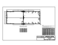
5<br />
1-1/2"OD METALLIC MAST DIPOLES SPACED 60" ON CENTERS<br />
3<br />
1<br />
8-9/16"<br />
10"<br />
2<br />
6<br />
7<br />
1<br />
4<br />
8<br />
1<br />
A<br />
B<br />
1/4"<br />
A+B<br />
NOTE-2<br />
C<br />
30"<br />
60"<br />
60"<br />
60"<br />
VERTICAL DIPOLE-1<br />
(TOP)<br />
VERTICAL DIPOLE-2<br />
VERTICAL DIPOLE-3<br />
VERTICAL DIPOLE-4<br />
(BOTTOM)<br />
60"<br />
60"<br />
ANTENNA-1<br />
50<br />
ANTENNA-2<br />
50<br />
60" 120"<br />
ANTENNA-3<br />
50<br />
ANTENNA-4<br />
A = 40-1/8"<br />
100<br />
COAX<br />
TEE<br />
100<br />
B = 40-1/8"<br />
C = 40-1/8"<br />
100<br />
COAX<br />
TEE<br />
100<br />
1<br />
2<br />
ITEM QTY<br />
1 15'<br />
2 4<br />
3 4<br />
4 24"<br />
5 8<br />
6 16<br />
7 16<br />
8 16<br />
DESCRIPTION<br />
SOURCE<br />
ALUMINUM TUBING, 1-3/8" OD<br />
www.texastowers.com<br />
SINGLE SOCKET TEE, ALUMINUM, KEE LITE L10-6<br />
www.keelite.com/us/<br />
4-HOLE SQUARE FLANGE, ALUMINUM, KEE LITE L152-6<br />
www.keelite.com/us/<br />
FIBERGLASS TUBING, 1-1/4" OD<br />
www.mgs4u.com<br />
V-BOLT SADDLE CLAMP, 1/2" TO 1-3/4", DXE-CAVS-1P<br />
www.dxengineering.com<br />
6-32 X 1-3/4", SS, PAN HEAD MACH. SCREW, McMASTER 91772A158 www.mcmaster.com<br />
#6 FLAT WASHER, SS, McMASTER 92141A007<br />
#6 LOCK NUT, SS, McMASTER 91831A007<br />
www.mcmaster.com<br />
www.mcmaster.com<br />
NOTES<br />
1. STRAP COAX ALONG ANTENNA WITH CABLE TIES. SEAL TERMINATIONS WITH COAX-SEAL.<br />
2. THE ALUMINUM TEE HAS ONLY ONE SET SCREW; COMBINE DIMENSIONS A & B TO MAKE ONE TUBE.<br />
50 E = 66-7/8"<br />
COAX<br />
100<br />
TEE<br />
3<br />
50<br />
100<br />
50<br />
F = 66-7/8"<br />
50 OHM COAX<br />
TO TRANSCEIVER<br />
ANTENNA-1<br />
50<br />
100<br />
60" COAX<br />
1<br />
50 50 OHM COAX<br />
TEE<br />
TO TRANSCEIVER<br />
100<br />
ANTENNA-2<br />
50<br />
A = 40-1/8"<br />
B = 40-1/8"<br />
50<br />
D = 40-1/8"<br />
ALUMINUM VERTICAL DIPOLE<br />
SCALE: 1/4:1<br />
FREE SPACE GAIN: 9.9 dBi<br />
BEAMWIDTH: 18 DEG<br />
Z: 50 OHMS<br />
METALLIC MAST<br />
1-1/2"OD<br />
4-ELEMENT<br />
PHASING HARNESS<br />
2-ELEMENT<br />
PHASING HARNESS<br />
DIPOLE<br />
LOCATION<br />
1 (TOP)<br />
2 & 3<br />
4 (BOTTOM)<br />
CENTERLINE DIMENSIONS<br />
A<br />
17-3/8"<br />
17-5/16"<br />
17-3/16"<br />
B<br />
3-1/2"<br />
3-15/32"<br />
3-7/16"<br />
C<br />
13-5/8"<br />
13-19/32"<br />
13-1/2"<br />
A + B<br />
20-7/8"<br />
20-25/32"<br />
20-5/8"<br />
4-ELEMENT VERTICAL DIPOLE ARRAY<br />
ALUMINUM ASSEMBLY<br />
NTS<br />
DESIGN: <strong>KG4JJH</strong> 11/15/05<br />
TESTED: <strong>KG4JJH</strong><br />
<strong>KG4JJH</strong><br />
2-METER VERTICAL DIPOLE ARRAY<br />
PHASING HARNESS &<br />
CLAMP-ON ALUMINUM ARRAY DETAILS<br />
SCALE: NOTED SHEET 4 OF 4 REV. 0<br />
A 2-<strong>Meter</strong> <strong>Vertical</strong> <strong>Dipole</strong> <strong>Array</strong>, <strong>KG4JJH</strong> Attachment 9 of 9