VocalMaster - A Speech Processor for Low Power Operators - KG4JJH
VocalMaster - A Speech Processor for Low Power Operators - KG4JJH
VocalMaster - A Speech Processor for Low Power Operators - KG4JJH

Create successful ePaper yourself
Turn your PDF publications into a flip-book with our unique Google optimized e-Paper software.
<strong>VocalMaster</strong>—A <strong>Speech</strong> <strong>Processor</strong><br />
<strong>for</strong> <strong>Low</strong> <strong>Power</strong> <strong>Operators</strong><br />
Build this versatile and attractive accessory <strong>for</strong> the Yaesu FT-817<br />
to give you more talk power.<br />
Allen Baker, <strong>KG4JJH</strong><br />
I<br />
have had a lot of fun operating low<br />
power with my Yaesu FT-817 portable<br />
HF transceiver, but have often<br />
wished that it had some audio or RF<br />
processing to add a little SSB punch. There<br />
are some excellent audio processing accessories<br />
available commercially, but I thought<br />
this would make a great homebrew project<br />
reminiscent of the early Heathkit days. With<br />
this in mind, I began to look <strong>for</strong> suitable<br />
building blocks to bring this idea to life.<br />
Design Goals<br />
I wanted to incorporate several design<br />
goals. First, the enclosure should be smaller<br />
than my radio, aesthetically pleasing, and<br />
made of steel or aluminum to provide RF<br />
shielding. Second, all of the components<br />
should mount on a printed circuit board<br />
with no point-to-point wiring to jacks or<br />
controls. Third, the input and output jacks<br />
must match the rig’s microphone connector.<br />
Fourth, I wanted some visual feedback<br />
on what was going on inside the box, such<br />
as an output level meter. And fifth, a built-in<br />
signal generator <strong>for</strong> antenna tuning would<br />
be an added bonus. The end result would<br />
combine all of these features into a small<br />
package that includes RF filtering and front<br />
panel controls, and is powered from the rig’s<br />
mic voltage.<br />
One of the first challenges was finding a<br />
compressor IC that would operate on the 5 V<br />
dc available at my radio’s mic jack. Several<br />
ICs are available that are used in professional<br />
audio equipment but they require ±12 V dc.<br />
The Analog Devices SSM2165/2166 series<br />
of ICs will operate on 5 V dc and I found<br />
several articles on their implementation. 1<br />
Un<strong>for</strong>tunately, the manufacturer has discontinued<br />
the dual in-line package (DIP) version<br />
of this device. They now only offer the chips<br />
as tiny surface mounted devices (SMD) that<br />
are much harder to install. After much con-<br />
sternation, I decided to prototype the circuit<br />
using a solderless breadboard and then lay<br />
out a printed circuit board.<br />
Circuit Description<br />
The fact that the SSM2166 combines a<br />
mic preamplifier, noise gate, compressor<br />
and limiter into one IC explains its popularity.<br />
A low-noise voltage controlled amplifier<br />
(VCA) provides gain that is adjusted by a<br />
control loop to provide compression. The<br />
compression ratio can be varied from 1:1<br />
to 15:1 relative to a rotation point. Signals<br />
above this rotation point, or limiting threshold,<br />
can then be limited to eliminate overload.<br />
A noise gate with adjustable time release prevents<br />
amplification of noise or hum. The unit<br />
per<strong>for</strong>ms all of this while boasting low noise<br />
and distortion over a 20 kHz bandwidth. The<br />
resulting microphone audio signal is thus<br />
optimized <strong>for</strong> communication use. Figure 1<br />
shows the input-output response at different<br />
Figure 1—<br />
Compressor<br />
input-output<br />
response<br />
at different<br />
compression<br />
settings.<br />
1<br />
Notes appear on page 35.<br />
From January 2006 QST © ARRL
From January 2006 QST © ARRL
Figure 2—Detailed schematic diagram and<br />
parts list <strong>for</strong> the <strong>VocalMaster</strong>. Resistors are<br />
1<br />
⁄4 W, 1%. Most components are stocked by<br />
major distributors such as DigiKey (www.<br />
digikey.com), Mouser (www.mouser.<br />
com) and Ocean State Electronics (www.<br />
oselectronics.com). Some special<br />
parts are available from Palomar (www.<br />
palomar-engineers.com), ExpressPCB<br />
(www.expresspcb.com), Small Bear<br />
Electronics (www.smallbearelec.com)<br />
and McMaster-Carr (www.mcmastercarr.com).<br />
C1—0.1 µF, 100 V polyester capacitor.<br />
C2, C4, C11, C16—10 µF, 16 V electrolytic<br />
capacitor.<br />
C3, C9, C13, C18—0.1 µF, 50 V ceramic<br />
capacitor.<br />
C5—2.2 µF, 16 V electrolytic capacitor.<br />
C6—22 µF, 16 V electrolytic capacitor.<br />
C7—0.001 µF, 50 V ceramic capacitor.<br />
C8, C10, C12, C20—1.0 µF, 16 V electrolytic<br />
capacitor.<br />
C14—0.01 µF, 100 V polystyrene<br />
capacitor, 5%.<br />
C15, C17—0.01 µF, 50 V ceramic capacitor.<br />
C19—330 µF, 16 V electrolytic capacitor.<br />
D1-D6—1N4148 diode.<br />
D7, D8—1N4001 diode.<br />
DS1-DS3—2 mA green LED<br />
(Mouser 645-551-1307).<br />
DS4—2 mA yellow LED<br />
(Mouser 645-551-1207).<br />
DS5—2 mA red LED (Mouser 645-551-1107).<br />
FB1-FB8—Ferrite bead (Palomar FB-1,<br />
Mix 43).<br />
J1-J2—RJ-45 connector<br />
(Mouser 154-UL6883).<br />
R1—1.24 kΩ metal film resistor.<br />
R2, R5, R6—6.98 kΩ metal film resistor.<br />
R3, R7, R20—10 kΩ metal film resistor.<br />
R4—17.4 kΩ metal film resistor.<br />
R8, R9—22 kΩ metal film resistor.<br />
R10—6.2 kΩ metal film resistor.<br />
R11-R13, R15, R16, R23-26, R28-R30—<br />
100 kΩ metal film resistor.<br />
R14, R17—200 kΩ metal film resistor.<br />
R18—1 kΩ metal film resistor.<br />
R19—100 kΩ single turn trimpot<br />
(Mouser 652-3386P-1-103T).<br />
R21—500 kΩ, 9 mm potentiometer, linear<br />
taper (Mouser 317-2081-500K).<br />
R22—18 kΩ metal film resistor.<br />
R27—249 kΩ metal film resistor.<br />
R31—50 kΩ, 9 mm potentiometer, linear<br />
taper (Mouser 317-2081-50K).<br />
R32—1 MΩ, 9 mm potentiometer, linear<br />
taper (Mouser 317-2081-1M).<br />
S1—DPDT toggle switch (Mouser 10TF160).<br />
S2—SPDT toggle switch (Mouser 10TF130).<br />
U1—SSM2166P 14 pin DIP mic preamp IC<br />
(Small Bear Electronics SSM2166P).<br />
U1 (Alternate)—SSM2166S 14 pin SMD mic<br />
preamp IC (DigiKey SSM2166S-ND).<br />
U2—LM324 single supply 14 pin DIP op<br />
amp IC (Mouser 595-LM324AN).<br />
U3—CD4093 quad 14 pin DIP two-input<br />
NAND Schmitt trigger IC (Mouser 595-<br />
CD4093BE).<br />
U4—LM3915 18 pin DIP LED dot/bar driver<br />
IC (DigiKey LM3915N-1-ND).<br />
PCB—Two sided printed circuit board<br />
(Express PCB).<br />
Aluminum enclosure, 4.7×4.1×1.2 inches<br />
(Mouser 546-1455L1201BK).<br />
RJ-45 Patch Cable, 2 feet long.<br />
Brass hex spacer, 4-40 × 1 ⁄4 inch (Mouser<br />
534-1450A).<br />
Pan head machine screw with internal<br />
washer, 4-40 × 3 ⁄16 inch (McMaster-Carr<br />
#90403A104).<br />
DIP IC socket, 14 pin (Mouser<br />
517-ICE-143-S-TG30).<br />
DIP IC Socket, 18 pin (Mouser 517-ICE-183-<br />
S-TG30).<br />
Figure 3—Inside top view of the completed <strong>VocalMaster</strong>.<br />
compression settings. Figure 2 provides the<br />
schematic and parts list.<br />
Controls<br />
All user controls are accessible from the<br />
front panel. While they may end up being<br />
set-and-<strong>for</strong>get controls after they have been<br />
properly adjusted, I prefer to have them<br />
within easy reach <strong>for</strong> tweaking. The potentiometers<br />
were selected to fit in the small<br />
enclosure and do not require knobs. BYPASS<br />
switch S1 toggles the processing IN and OUT<br />
to let you get signal report feedback and<br />
<strong>for</strong> FM use. Switch S2 establishes the level<br />
detector averaging time constant. With S2<br />
in the FAST position, the attack time is 22 ms<br />
and the release time is 240 dB/s. With S2 the<br />
SLOW position the attack time is 220 ms and<br />
the release time is 12 dB/second.<br />
<strong>Processor</strong> Controls<br />
The processor, U1, an SSM2166, 2 has its<br />
input buffer gain initially set to 6 dB and the<br />
VCA gain is set to 0 dB. The NOISE GATE<br />
control sets the noise gate threshold. Turning<br />
clockwise reduces the threshold and sets the<br />
level below which input signals are downward<br />
expanded at a ratio of 1:3. The COMP<br />
RATIO control establishes the compression<br />
ratio over the range of 1:1 to 15:1. Turning<br />
clockwise increases the ratio. The LIMITING<br />
THRESHOLD control determines the level at<br />
which limiting begins. Turning clockwise<br />
reduces the level at which limiting occurs.<br />
Output Level Meter<br />
The output of U1 (pin 13) is fed to U2, an<br />
LM324. 3 Amplifiers U2A, U2B and U2C<br />
<strong>for</strong>m a precision full-wave peak detector that<br />
drives the input of U4, an LM3915. 4 U4 is<br />
set <strong>for</strong> dot mode and drives low current<br />
LEDs to minimize the current demand.<br />
Illumination of the green LEDs with an<br />
occasional yellow LED indicates output<br />
levels in a “safe” area of operation. The red<br />
LED indicates a distorted signal and should<br />
rarely illuminate if everything is adjusted<br />
properly. Trimpot R19 allows the meter to<br />
be adjustable.<br />
Mic Input and Output<br />
The RJ-45 microphone input jack at J1<br />
matches the FT-817 microphone. The microphone<br />
output at J2 uses a similar connector<br />
and is connected to the FT-817 microphone<br />
input via a standard CAT-5 computer network<br />
patch cord. The microphone and patch<br />
cables are not shielded. Instead, they rely on<br />
the fact that twisted-pair wires inherently<br />
reject noise. All eight microphone wires<br />
employ ferrite beads to attenuate any RF. If<br />
your <strong>VocalMaster</strong> is <strong>for</strong> a radio with different<br />
mic connectors, make the appropriate substitution<br />
of connector types to fit your radio<br />
and microphone.<br />
Signal Generator<br />
A novel circuit 5 <strong>for</strong> providing an 800 Hz<br />
tuning signal is provided by U3, a CD4093.<br />
U3C <strong>for</strong>ms an astable oscillator with the<br />
frequency determined by 2/(R27 × C14).<br />
A square wave will be produced at pin 10<br />
whenever pins 2 and 6 are pulled low. R28<br />
and C15 <strong>for</strong>m a simple 160 Hz low-pass<br />
filter that modifies the output into a triangular<br />
wave. U3D powers down U1 when<br />
the signal generator is active and mutes the<br />
microphone. To activate the generator, press<br />
and hold the microphone push-to-talk (PTT)<br />
button and then press the DOWN button. The<br />
From January 2006 QST © ARRL
Table 1<br />
FT-817 Adjustment Settings<br />
Control Function Initial Full CCW Midpoint Full CW <strong>KG4JJH</strong><br />
Position 0 5 10 settings<br />
R32 Noise Gate 10 15 mV rms 0.55 mV rms 100 µV rms 10<br />
Threshold (–34 dBu 10 ) (–63 dBu) (–78 dBu) (–63 dBu)<br />
R21 Compression 0 1:1 10:1 15:1 5<br />
Ratio<br />
R31 Limiting 0 0.1 V rms 0.040 V rms 0.025 V rms 5<br />
Threshold (–18 dBu) (–26 dBu) (–30 dBu) (–26 dBu)<br />
S1 Bypass IN IN<br />
S2 Attack SLOW SLOW<br />
Release<br />
functionality of the microphone UP, DOWN,<br />
and FAST buttons are not affected.<br />
<strong>Power</strong> Requirements<br />
The current requirements (measured values)<br />
<strong>for</strong> this circuit are 13.9 mA during normal<br />
operation and 4.4 mA when the signal<br />
generator is on. The FT-817 mic power lead<br />
was found to deliver up to approximately<br />
15 mA be<strong>for</strong>e the voltage dropped below<br />
4.85 V dc, indicating that it should power<br />
the <strong>VocalMaster</strong> without any problems. For<br />
other radios, the mic supply voltage may or<br />
may not be up to the task. If not, a different<br />
source of 5 V must be found from within or<br />
outside the radio.<br />
From January 2006 QST © ARRL<br />
Printed Circuit Board<br />
I was <strong>for</strong>tunate to have an SSM2166S<br />
on hand, courtesy of Analog Devices, and<br />
this prompted me to start the prototype. I<br />
made an SMD to DIP adapter to allow me<br />
to use a solderless breadboard designed<br />
<strong>for</strong> DIP devices. After I had completed the<br />
PCB layout I discovered a source <strong>for</strong> the<br />
DIP package, the SSM2166P, 6 <strong>for</strong> which I<br />
completed a second version. Both versions of<br />
the PCB employ the manufacturer’s advice<br />
on star grounding and short lead lengths to<br />
minimize instability. Builders should get the<br />
desired chip be<strong>for</strong>e ordering one of the two<br />
versions of the PCB.<br />
I ordered prototype printed circuit boards<br />
from ExpressPCB. 7 I chose the most economical<br />
approach by ordering boards that<br />
are double sided with plated through holes<br />
but do not have a solder mask or component<br />
silk screening. Regardless of the manufacturer,<br />
groups of builders or clubs should get<br />
together and order the boards in quantities<br />
to reduce the cost. You can see the various<br />
cost breakdowns by installing the free PCB<br />
software and loading one of the layouts,<br />
<strong>VocalMaster</strong>-DIP.pcb or <strong>VocalMaster</strong>-SMD.<br />
pcb. If the PCB does not have plated-through<br />
holes, be sure to solder the components on<br />
both sides of the board. Additionally, if the<br />
pad is a feedthrough, insert a short length of<br />
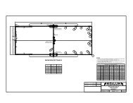
wire and solder on both sides. The inside top<br />
view of the completed <strong>VocalMaster</strong> is shown<br />
in Figure 3. Check with the author to determine<br />
the availability of fabricated boards.<br />
Printed Circuit Assembly<br />
Install the components by referring to the<br />
printed circuit board (PCB) assembly drawing<br />
<strong>for</strong> part numbers and locations, and the<br />
materials list <strong>for</strong> corresponding values. For<br />
the DIP version, use a small soldering iron<br />
of 25 W or less with a standard small tip.<br />
For the SMD version, a very tiny tipped iron<br />
( 1 ⁄16 inch) and a magnifier are mandatory <strong>for</strong><br />
soldering the SSM2166P.<br />
A beginners guide to surface mount<br />
technology is a good starting point to get<br />
you acquainted with the tools and methods<br />
involved. 8 Work with plenty of light<br />
and use small gauge solder sparingly, as<br />
the PCB pads are small. Too much solder<br />
will increase the chance of a solder bridge,<br />
especially on boards without a solder mask.<br />
Cleaning the tip on a damp sponge be<strong>for</strong>e<br />
every solder joint will decrease the chances<br />
of a faulty connection. Although not mandatory,<br />
I encourage the use of IC sockets to<br />
aid in testing and troubleshooting. Observe<br />
polarity on all ICs, diodes and electrolytic<br />
capacitors. All components should be<br />
mounted close to the board to minimize lead<br />
lengths.<br />
Trimpot R19 will be adjusted following<br />
assembly to illuminate the red LED on audio<br />
peaks that produce distortion in the transmitted<br />
signal.<br />
Save the clipped ends of component<br />
wires <strong>for</strong> installing ferrite beads FB1-FB8.<br />
Install all components except U1, U2, U3<br />
and U4. Take your time and check your work.<br />
If your eyes are as bad as mine, a magnifying<br />
glass, headband or worklight may come<br />
in handy. When you are satisfied, connect<br />
MIC OUT to the radio microphone input with<br />
a short jumper cable. Attach the negative<br />
lead of a dc voltmeter to the PCB common<br />
connection. Turn on the radio, and, using the<br />
voltmeter positive lead, check <strong>for</strong> 5 ±0.2 V<br />
dc at the following locations: U1, pin 14; U2,<br />
pin 4; U3, pin 14, and U4, pin 3. If all voltages<br />
are okay, remove power and connect the<br />
mic to the MIC IN jack, J1. Place S1 in the OUT<br />
position and ensure that the radio is functioning<br />
normally, including the microphone<br />
audio, UP, DOWN and FAST functions. If you<br />
experience problems go back and inspect the<br />
PCB <strong>for</strong> incorrectly installed components,<br />
reversed polarities, solder bridges, and faulty<br />
solder joints. When the test is successful,<br />
remove power and install the ICs in their<br />
sockets. Pin 1 is identified with a square pad<br />
on the PCB. Make sure all pins are aligned<br />
be<strong>for</strong>e pressing them into the sockets or you<br />
may bend them.<br />
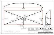
Enclosure<br />
Using rubber cement, secure the templates<br />
(see drawing sheet 3, www.arrl.org/<br />
files/qst-binaries/Baker0106.zip) and drill<br />
all holes on the front and rear panels. The<br />
rectangular holes on the rear panel will also<br />
require a file and some elbow grease to get<br />
them properly sized. To improve the appearance<br />
of the front panel holes, use a countersinking<br />
bit to lightly remove the rough<br />
edges. You may want to blacken the hole<br />
edges using an aluminum blacking solution,<br />
sold in gun stores. I used white enamel paint<br />
on the control indicator marks to make them<br />
more visible. Using a small jeweler’s screwdriver,<br />
dip the tip into the paint and touch<br />
the inside of the control slots. Use small<br />
amounts and allow the paint to flow only<br />
into the slot. Clean up using a cotton swab<br />
damped with paint thinner.<br />
Labeling was added using white dry<br />
transfer letters. Print a full size template<br />
onto clear film. Tape the panel to a flat<br />
surface and clean it with rubbing alcohol.<br />
Tape the top edge of the clear template over<br />
the panel. Insert the dry transfer sheet in<br />
between, line up each character under the<br />
template and burnish. I used 1 ⁄8, 3 ⁄32 and 1 ⁄16<br />
inch characters found in the HO railroad<br />
section of my local hobby shop. 9 Clean up<br />
with masking tape and cotton swabs moistened<br />
with alcohol. Seal the lettering by<br />
spraying on two light coats of clear lacquer<br />
or decal sealer. Figure 4 shows the details of<br />
the front panel lettering.<br />
It is important to note that the removable<br />
panel is located at the enclosure top. This is to<br />
allow access to R19 and to prevent the PCB<br />
traces from contacting the enclosure PCB<br />
mounting channels. Attach the front bezel
and panel and slide the PCB into the bottom<br />
rails of the enclosure from the rear until the<br />
front of the PCB touches the inside of the<br />
front panel. Mark the mounting hole location<br />
on the bottom of the enclosure and drill a 5 ⁄32<br />
inch diameter hole. Scrape away any paint or<br />
anodizing around the inside of this hole to<br />
ensure a good electrical connection between<br />
the enclosure and the PCB. Attach the spacer<br />
on the bottom center of the completed PCB<br />
with a 4-40 × 3 ⁄16 inch screw with internal<br />
lockwasher and slide it into the enclosure.<br />
Guide the controls through the front panel<br />
cutouts and insert the panel screws. Be very<br />
careful not to over tighten the front and rear<br />
panel screws as the aluminum holes are easily<br />
stripped. After adjusting R19 in the next<br />
section, slide in the top panel, rear bezel, and<br />
rear panel and install the four rubber feet on<br />
the bottom. Complete the assembly by securing<br />
the PCB mounted spacer with a 4-40 × 3 ⁄16<br />
inch screw with internal lockwasher from the<br />
enclosure bottom.<br />
Setup and Operation<br />
The following instructions are FT-817<br />
specific. For other radios, check the manual<br />
<strong>for</strong> the appropriate control function. FT-817<br />
menu 46 (SSB MIC) should initially be set<br />
to the default value of 50. Plug one end of<br />
a standard 1 to 3 foot CAT-5 patch cable<br />
into MIC OUT jack J2 and the other end into<br />
the FT-817 microphone jack. Plug the MH-<br />
31 microphone into MIC IN jack J1. (Please<br />
note that the <strong>VocalMaster</strong> is designed to<br />
work only with the standard MH-31 microphone.<br />
The optional DTMF microphone is<br />
not compatible.) Connect a dummy load to<br />
the radio, and monitor the transmitted signal<br />
on a second rig using headphones. It is very<br />
important to monitor your transmitted audio<br />
until you have adjusted R19 and are familiar<br />
with the operation of the <strong>VocalMaster</strong>, as<br />
improper settings may produce a noisy or<br />
distorted signal.<br />
While monitoring your transmitted signal,<br />
adjust the controls as follows: TIME<br />
CONSTANT to SLOW, NOISE GATE to 10, COMP<br />
RATIO to 10, and LIMIT THRESHOLD to 0. At<br />
these settings you should hear distortion in<br />
the transmitted signal. Adjust R19 to illuminate<br />
the red LED on these audio peaks.<br />
The LED output<br />
level meter is always<br />
active when the<br />
bypass switch is in<br />
the IN position. This<br />
feature allows you<br />
to adjust the controls<br />
without transmitting<br />
(ie, PTT is off).<br />
Initially, set the time<br />
constant to SLOW,<br />
NOISE GATE to 10,<br />
COMP RATIO to 1, and<br />
LIMIT THRESHOLD to<br />
0. Speak into the microphone with the processor<br />
IN and note that two or three green<br />
LEDs illuminate. Continue speaking and<br />
slowly turn COMP RATIO clockwise until the<br />
red LED turns on. A high compression ratio<br />
coupled with a low limiting threshold will<br />
yield a high output level, which could overload<br />
the radio’s audio input. These settings<br />
will also raise the background noise level<br />
and could introduce audible distortion and<br />
“breathing or pumping” effects. Reduce the<br />
output level by lowering the compression<br />
ratio and/or lowering the limiting threshold.<br />
Turn LIMIT THRESHOLD clockwise and notice<br />
that the output level diminishes. With the<br />
compression ratio set to 2:1, a 6 dB change<br />
of the input signal level in the compression<br />
region causes a 3 dB change in the output<br />
level. Likewise, at 10:1 compression, a 10<br />
dB change of the input signal level in the<br />
compression region causes a 1 dB change<br />
in the output level. Holding the microphone<br />
closer to your mouth reduces ambient room<br />
noise and gives the audio more presence. If<br />
you speak softly or hold the microphone farther<br />
away, access FT-817 Menu 46 <strong>for</strong> further<br />
SSB microphone gain adjustments.<br />
The controls are somewhat interactive so<br />
experiment with the settings to hear how they<br />
affect the audio. Table-1 lists initial positions,<br />
general parameters at various settings,<br />
and the optimum settings <strong>for</strong> my operating<br />
conditions.<br />
The compression ratio will keep the<br />
output steady over a wide range of microphone<br />
to speaker distance, and the noise<br />
gate will reduce background noises. Signals<br />
above the limiting threshold are limited at<br />
a compression ratio of 15:1 to eliminate<br />
overloads. A graph of the Input/Output<br />
Characteristics is shown in Figure 1, and<br />
two audio WAV files (<strong>VocalMaster</strong>-Quiet.<br />
wav and <strong>VocalMaster</strong>-Noisy.wav) are posted<br />
on the ARRL Web site (www.arrl.org/files/<br />
qst-binaries/Baker0106.zip) to let you hear<br />
the sound of a <strong>VocalMaster</strong>ed SSB signal in<br />
a quiet and noisy environment.<br />
Figure 4—Details of the<br />
front panel lettering.<br />
Conclusion<br />
I am delighted to report that all of the<br />
design goals have been met. The aluminum<br />
enclosure is smaller than my FT-817 11 and<br />
provides good shielding. All components<br />
mount on a printed circuit board, including<br />
the microphone connectors. An LED output<br />
level meter provides visual feedback, and a<br />
built-in signal generator simplifies antenna<br />
tuning. As an added bonus, the Yaesu FT-857<br />
and FT-897 also use the MH-31 microphone,<br />
so the processor can be used on all three rigs.<br />
On-the-air reports with the FT-817 have been<br />
very favorable with an average 6 dB increase<br />
in signal strength. The <strong>VocalMaster</strong> will<br />
enhance your SSB signal and you will be<br />
proud to place this eye-catching accessory<br />
next to your rig. Once you have rounded up<br />
all of the parts this project can be completed<br />
in a weekend, so heat up your soldering iron<br />
and give your QRP station some pizzazz!<br />
Notes<br />
1 M. Gonsior, W6FR, “MikeMaster—A Microphone<br />
Preamplifier with Noise Gating and<br />
Compression, QST, Mar 1998, pp 33-36;<br />
P. Salas, AD5X, “FT-817 <strong>Speech</strong> Compressor,”<br />
www.eham.net/articles/2627; J.<br />
Orman, “Q&D Compressor 2,” www.muzique.<br />
com/ssm2166.htm.<br />
2 Analog Devices, “Microphone Preamplifier with<br />
Noise Gating and Compression, SSM-2166<br />
Data Sheet,” www.analog.com/UploadedFiles/<br />
Data_Sheets/83095497SSM2166_b_.pdf.<br />
3 LM123 LM224 LM324 LM2902 <strong>Low</strong> <strong>Power</strong> Quad<br />
Operational Amplifiers, National Semiconductor,<br />
www.national.com/ds/LM/LM124.pdf.<br />
4 LM3915 Dot Bar Display Driver, National<br />
Semiconductor, www.national.com/ds/LM/<br />
LM3915.pdf.<br />
5 K. Theurich, DGØZB, “Dynamic Compressor <strong>for</strong><br />
the FT-817,” FunkAmateur, Apr 2002, p 389.<br />
6 Steve Daniels of Small Bear Electronics has<br />
indicated that he has 200 of the SSM2166P<br />
chips with more available on the wholesale<br />
market; www.smallbearelec.com/Ordering/<br />
ICsCompExp.htm.<br />
7 ExpressPCB, printed circuit boards and free<br />
software, www.expresspcb.com. Contact<br />
the author to determine the availability of prefabricated<br />
PC boards.<br />
8 S Ulbing, N4UAU, “Surface Mount Technology—<br />
You Can Work With It!,” QST; Part 1, Apr 1999,<br />
pp 33-39; Part 2, May 1999, pp 48-50; Part 3,<br />
Jun 1999, pp 34-36; Part 4, Jul 1999, pp 38-<br />
41.<br />
9 Dry Transfer Decals, Woodland Scenes,<br />
#WOODT507.<br />
10 dBu is a means of expressing voltage, referenced<br />
to 0.775 V, regardless of impedance.<br />
One mW of power is dissipated if 0.775 V is<br />
applied to a 600 Ω load, so <strong>for</strong> a load impedance<br />
of 600 Ω, 0 dBu = 0 dBm.<br />
11 The <strong>VocalMaster</strong> was designed with the FT-<br />
817 in mind, but should work with any transceiver<br />
that uses a 600 Ω mic at the appropriate<br />
level and has 5 V available.<br />
Allen Baker, <strong>KG4JJH</strong>, received his license in<br />
2000, after a lifelong dream of becoming a<br />
ham. He holds a BS in Industrial Engineering<br />
from Tennessee Technological University<br />
and works as an Instrumentation & Controls<br />
Engineer <strong>for</strong> the company that operates the US<br />
Department of Energy weapons plant in Oak<br />
Ridge, Tennessee. Allen is active on SSB<br />
and the digital modes, enjoys the challenge<br />
of working QRP and loves to experiment with<br />
antennas and radio gear. He can be reached at<br />
211 Brochardt Blvd, Knoxville, TN 37934 or<br />
kg4jjh@arrl.net.<br />
From January 2006 QST © ARRL