WINNER II pdf - Final Report - Cept
WINNER II pdf - Final Report - Cept
WINNER II pdf - Final Report - Cept

Create successful ePaper yourself
Turn your PDF publications into a flip-book with our unique Google optimized e-Paper software.
<strong>WINNER</strong> <strong>II</strong> D1.1.2 V1.2<br />
d<br />
2<br />
2<br />
BS ,<br />
( ) ( )<br />
i MS<br />
= x<br />
k BS<br />
− x<br />
i MS<br />
+ y<br />
k BS<br />
− y<br />
i MS k<br />
. (5.1)<br />
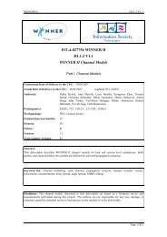
The LOS direction from BS i to MS k with respect to BS antenna array broad side is (see Figure 5-2)<br />
θ<br />
BSi<br />
, MSk<br />
⎧ ⎛ y<br />
⎪−<br />
arctan⎜<br />
⎪<br />
⎝<br />
x<br />
= ⎨<br />
⎪ ⎛ y<br />
⎜<br />
⎪−<br />
arctan<br />
⎩ ⎝<br />
x<br />
MSk<br />
MSk<br />
MSk<br />
MSk<br />
− y<br />
− x<br />
− y<br />
− x<br />
BSi<br />
BSi<br />
BSi<br />
BSi<br />
⎞<br />
⎟ + 90° − Ω<br />
⎠<br />
⎞<br />
⎟ − 90° − Ω<br />
⎠<br />
The angles and orientations are depicted in the figure below.<br />
BSi<br />
BSi<br />
,<br />
,<br />
when<br />
when<br />
x<br />
x<br />
MSk<br />
MSk<br />
≥ x<br />
< x<br />
BSi<br />
BSi<br />
(5.2)<br />
Ω BSi<br />
θ BS i , MS k<br />
Ω MSk<br />
θ MS , k BS i<br />
Figure 5-2: BS and MS antenna array orientations.<br />
Pairing matrix A is in the example case of Figure 5-2 a 6x3 matrix with values χ n,m ∈ {0,1}. Value 0<br />
stands for link celln to MSm is not modelled and value 1 for link is modelled.<br />
⎡χc1,<br />
⎢<br />
= ⎢<br />
χc2,<br />
⎢ M<br />
⎢<br />
⎣χc6,<br />
ms1<br />
ms1<br />
ms1<br />
χ<br />
χ<br />
χ<br />
c1,<br />
ms2<br />
c2,<br />
ms2<br />
M<br />
c6,<br />
ms2<br />
χ<br />
χ<br />
χ<br />
c1,<br />
ms3<br />
c2,<br />
ms3<br />
M<br />
c6,<br />
ms3<br />
⎤<br />
⎥<br />
⎥<br />
⎥<br />
⎥<br />
⎦<br />
A (5.3)<br />
The pairing matrix can be applied to select which radio links will be generated and which will not.<br />
5.1.2 Multi-cell simulations<br />
5.1.2.1 Single user (Handover)<br />
A handover situation is characterized by a MS moving from the coverage are of one BS to the<br />
coverage area of another BS. Figure 5-3 illustrates this setup.<br />
Page 51 (82)