WINNER II pdf - Final Report - Cept
WINNER II pdf - Final Report - Cept
WINNER II pdf - Final Report - Cept

Create successful ePaper yourself
Turn your PDF publications into a flip-book with our unique Google optimized e-Paper software.
<strong>WINNER</strong> <strong>II</strong> D1.1.2 V1.2<br />
5. Channel Model Usage<br />
The purpose of this chapter is to discuss issues concerning usage of the <strong>WINNER</strong> channel model for<br />
simulations.<br />
5.1 System level description<br />
5.1.1 Coordinate system<br />
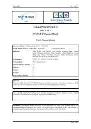
System layout in the Cartesian coordinates is for example the following:<br />
Figure 5-1: System layout of multiple base stations and mobile stations.<br />
All the BS and MS have (x,y) coordinates. MS and cells (sectors) have also array broad side<br />
orientation, where north (up) is the zero angle. Positive direction of the angles is the clockwise<br />
direction.<br />
Table 5-1: Transceiver coordinates and orientations.<br />
Tranceiver Co-ordinates Orientation [°]<br />
BS1 cell1 (x bs1 ,y bs1 ) Ω c1<br />
cell2 (x bs1 ,y bs1 ) Ω c2<br />
cell3 (x bs1 ,y bs1 ) Ω c3<br />
BS2 cell4 (x bs2 ,y bs2 ) Ω c4<br />
cell5 (x bs2 ,y bs2 ) Ω c5<br />
cell6 (x bs2 ,y bs2 ) Ω c6<br />
MS1 (x ms1 ,y ms1 ) Ω ms1<br />
MS2 (x ms2 ,y ms2 ) Ω ms2<br />
MS3 (x ms3 ,y ms3 ) Ω ms3<br />
Both the distance and line of sight (LOS) direction information of the radio links are calculated for the<br />
input of the model. Distance between the BS i and MS k is<br />
Page 50 (82)