WINNER II pdf - Final Report - Cept
WINNER II pdf - Final Report - Cept
WINNER II pdf - Final Report - Cept

Create successful ePaper yourself
Turn your PDF publications into a flip-book with our unique Google optimized e-Paper software.
<strong>WINNER</strong> <strong>II</strong> D1.1.2 V1.2<br />
In the LOS case substitute (4.12) by (4.13) to enforce the first cluster to the LOS direction ϕ LOS<br />
X ' + Y − X + Y − . (4.11)<br />
ϕ<br />
( ϕ ) ( ϕ ϕ )<br />
n<br />
= '<br />
n n n n 1 1<br />
<strong>Final</strong>ly add the offset angles α m from Table 4-1 to cluster angles<br />
ϕ<br />
n<br />
= ϕ + c α<br />
LOS<br />
, m n AoA m<br />
, (4.12)<br />
where c AoA is the cluster-wise rms azimuth spread of arrival angles (cluster ASA) in the Table 4-5.<br />
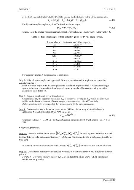
Table 4-1 Ray offset angles within a cluster, given for 1° rms angle spread.<br />
For departure angles φ n the procedure is analogous.<br />
Ray number m Basis vector of offset angles α m<br />
1,2 ± 0.0447<br />
3,4 ± 0.1413<br />
5,6 ± 0.2492<br />
7,8 ± 0.3715<br />
9,10 ± 0.5129<br />
11,12 ± 0.6797<br />
13,14 ± 0.8844<br />
15,16 ± 1.1481<br />
17,18 ± 1.5195<br />
19,20 ± 2.1551<br />
Step 7b If the elevation angles are supported: Generate elevation arrival angles ψ and elevation<br />
departure angles γ.<br />
Draw elevation angles with the same procedure as azimuth angles on Step 7. Azimuth rms angle<br />
spread values and cluster-wise azimuth spread values are replaced by corresponding elevation<br />
parameters from Table 4-6.<br />
Step 8: Random coupling of rays within clusters.<br />
Couple randomly the departure ray angles φ n,m to the arrival ray angles ϕ n,m within a cluster n, or<br />
within a sub-cluster in the case of two strongest clusters (see step 11 and Table 4-2).<br />
If the elevation angles are supported they are coupled with the same procedure.<br />
Step 9: Generate the cross polarisation power ratios (XPR) κ for each ray m of each cluster n.<br />
XPR is log-Normal distributed. Draw XPR values as<br />
10<br />
κ , (4.13)<br />
,<br />
10 X<br />
m n<br />
=<br />
where ray index m = 1,…,M, X ~ N(σ,µ) is Gaussian distributed with σ and µ from Table 4-5 for<br />
XPR.<br />
Coefficient generation:<br />
vv vh hv hh<br />
Step 10: Draw the random initial phase { Φ , Φ Φ }<br />
Φ for each ray m of each cluster n and<br />
n, m, n,<br />
m n,<br />
m,<br />
n,<br />
m<br />
for four different polarisation combinations (vv,vh,hv,hh). Distribution for the initial phases is uniform,<br />
Uni(-π,π).<br />
vv hh<br />
In the LOS case draw also random initial phases { Φ }<br />
Φ for both VV and HH polarisations.<br />
LOS<br />
,<br />
LOS<br />
Step 11: Generate the channel coefficients for each cluster n and each receiver and transmitter element<br />
pair u,s.<br />
For the N – 2 weakest clusters, say n = 3,4,…,N, and uniform linear arrays (ULA), the channel<br />
coefficient are given by:<br />
Page 40 (82)