WINNER II pdf - Final Report - Cept
WINNER II pdf - Final Report - Cept
WINNER II pdf - Final Report - Cept

Create successful ePaper yourself
Turn your PDF publications into a flip-book with our unique Google optimized e-Paper software.
<strong>WINNER</strong> <strong>II</strong> D1.1.2 V1.2<br />
Doppler information is not specified explicitly for CDL models. This is because Doppler is determined by<br />
the AoAs of the MPCs, MS speed and direction, and the specified antenna patterns at the MS and BS,<br />
upon which there are no restrictions, except in fixed feeder link scenarios, as discussed in the section of<br />
feeder link models.<br />
3.6.1 Cluster Delay Line models for mobile and portable scenarios<br />
Cluster delay line (CLD) models for all mobile scenarios have been generated from the corresponding<br />
generic models by selecting typical values from a set of random channel realisations. The CLD models<br />
consist of the average power, mean AoA, mean AoD, and angle spreads at the BS and MS associated with<br />
each cluster within the cluster delay line models. Tables of CDL parameters for the above-cited scenarios<br />
can be found in Section 6. Although AoA and AoD values are fixed, it is recommended to have<br />
directional variation for e.g. beamforming simulations by adding network layout related angle parameter<br />
Ω MS and Ω BS to all tabulated angles (see Figure 5-2).<br />
3.6.2 Cluster Delay Line models for fixed feeder links<br />
Only CDL models have been created for fixed feeder links (B5 scenarios). Model parameters have mostly<br />
been derived from the literature as described in [WIN1D54], but some of them have been created by<br />
applying models generated in <strong>WINNER</strong>. CDL models for B5 scenarios are given in the tables of Section<br />
6. As for the mobile and portable scenarios, any desired antenna patterns can be chosen. However, for<br />
scenarios B5a and B5b, at distances greater than 300 metres, the 3 dB beamwidth of the antenna at one<br />
end of the link should be less than 10 degrees, while that at the other end of the link should be less than<br />
53 degrees. Different parameters are specified in the cited tables for scenarios B5a, b, c, and d.<br />
For fixed link scenarios B5a, B5b, B5d and B5f, Doppler shifts are independent of AOAs. Instead, they<br />
are derived from considerations concerning the movement of interacting objects. One interacting object<br />
per cluster is modelled as having motion, while the others are fixed. Associated Doppler frequencies are<br />
specified in CDL tables. For the scenario B5c, two whole cluster are moving with random velocity.<br />
3.6.3 Complexity comparison of modelling methods<br />
Computational complexity of simulation of channel models is an important issue in system performance<br />
evaluations. Complexity comparison of <strong>WINNER</strong> modelling approach with the popular correlation matrix<br />
based method is studied in [KJ07]. A common supposition is that the correlation method is simpler and<br />
computationally more effective than the geometric method. Conclusion of [KJ07] is that complexity of<br />
both methods is about the same order of magnitude. With a high number of MIMO antenna pairs (>16)<br />
correlation based method is clearly more complex.<br />
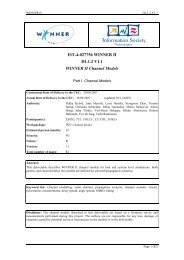
The computation complexity is compared in terms of the number of “real operations”. With the term “real<br />
operations” is equated complexity of real multiplication, division, addition and table lookup. In Figure 3-9<br />
the number of real operations per delay tap per MIMO channel time sample (matrix impulse response),<br />
with different MxN MIMO antenna numbers, is depicted assuming 10 or 20 rays (M in eq. 3.3) and 8 th<br />
order <strong>II</strong>R filter in correlation matrix method. It was also noted that complexity of channel realisation<br />
generation is several order of magnitudes lower than computational complexity of simulation of channel<br />
convolution.<br />
Figure 3-9. Computational complexity comparison.<br />
Page 36 (82)