WINNER II pdf - Final Report - Cept
WINNER II pdf - Final Report - Cept
WINNER II pdf - Final Report - Cept

You also want an ePaper? Increase the reach of your titles
YUMPU automatically turns print PDFs into web optimized ePapers that Google loves.
<strong>WINNER</strong> <strong>II</strong> D1.1.2 V1.2<br />
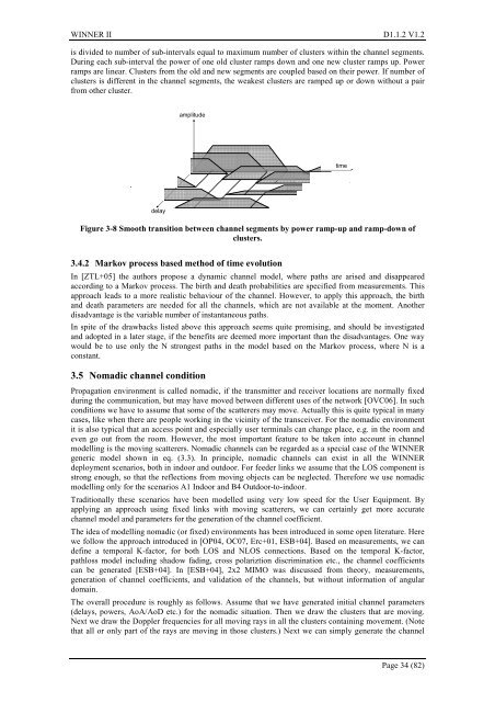
is divided to number of sub-intervals equal to maximum number of clusters within the channel segments.<br />
During each sub-interval the power of one old cluster ramps down and one new cluster ramps up. Power<br />
ramps are linear. Clusters from the old and new segments are coupled based on their power. If number of<br />
clusters is different in the channel segments, the weakest clusters are ramped up or down without a pair<br />
from other cluster.<br />
amplitude<br />
time<br />
delay<br />
Figure 3-8 Smooth transition between channel segments by power ramp-up and ramp-down of<br />
clusters.<br />
3.4.2 Markov process based method of time evolution<br />
In [ZTL+05] the authors propose a dynamic channel model, where paths are arised and disappeared<br />
according to a Markov process. The birth and death probabilities are specified from measurements. This<br />
approach leads to a more realistic behaviour of the channel. However, to apply this approach, the birth<br />
and death parameters are needed for all the channels, which are not available at the moment. Another<br />
disadvantage is the variable number of instantaneous paths.<br />
In spite of the drawbacks listed above this approach seems quite promising, and should be investigated<br />
and adopted in a later stage, if the benefits are deemed more important than the disadvantages. One way<br />
would be to use only the N strongest paths in the model based on the Markov process, where N is a<br />
constant.<br />
3.5 Nomadic channel condition<br />
Propagation environment is called nomadic, if the transmitter and receiver locations are normally fixed<br />
during the communication, but may have moved between different uses of the network [OVC06]. In such<br />
conditions we have to assume that some of the scatterers may move. Actually this is quite typical in many<br />
cases, like when there are people working in the vicinity of the transceiver. For the nomadic environment<br />
it is also typical that an access point and especially user terminals can change place, e.g. in the room and<br />
even go out from the room. However, the most important feature to be taken into account in channel<br />
modelling is the moving scatterers. Nomadic channels can be regarded as a special case of the <strong>WINNER</strong><br />
generic model shown in eq. (3.3). In principle, nomadic channels can exist in all the <strong>WINNER</strong><br />
deployment scenarios, both in indoor and outdoor. For feeder links we assume that the LOS component is<br />
strong enough, so that the reflections from moving objects can be neglected. Therefore we use nomadic<br />
modelling only for the scenarios A1 Indoor and B4 Outdoor-to-indoor.<br />
Traditionally these scenarios have been modelled using very low speed for the User Equipment. By<br />
applying an approach using fixed links with moving scatterers, we can certainly get more accurate<br />
channel model and parameters for the generation of the channel coefficient.<br />
The idea of modelling nomadic (or fixed) environments has been introduced in some open literature. Here<br />
we follow the approach introduced in [OP04, OC07, Erc+01, ESB+04]. Based on measurements, we can<br />
define a temporal K-factor, for both LOS and NLOS connections. Based on the temporal K-factor,<br />
pathloss model including shadow fading, cross polariztion discrimination etc., the channel coefficients<br />
can be generated [ESB+04]. In [ESB+04], 2x2 MIMO was discussed from theory, measurements,<br />
generation of channel coefficients, and validation of the channels, but without information of angular<br />
domain.<br />
The overall procedure is roughly as follows. Assume that we have generated initial channel parameters<br />
(delays, powers, AoA/AoD etc.) for the nomadic situation. Then we draw the clusters that are moving.<br />
Next we draw the Doppler frequencies for all moving rays in all the clusters containing movement. (Note<br />
that all or only part of the rays are moving in those clusters.) Next we can simply generate the channel<br />
Page 34 (82)