WINNER II pdf - Final Report - Cept
WINNER II pdf - Final Report - Cept
WINNER II pdf - Final Report - Cept

Create successful ePaper yourself
Turn your PDF publications into a flip-book with our unique Google optimized e-Paper software.
<strong>WINNER</strong> <strong>II</strong> D1.1.2 V1.2<br />
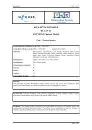
Name<br />
Center<br />
frequency<br />
PULA8<br />
(PULA8@10W)<br />
UCA16 PUCPA24 SPUCPA4x24<br />
[GHz] 5.2 5.2 5.2 5.2<br />
Bandwidth [MHz] 120 120 120 120<br />
Max. Power [dBm] 27 (40) 27 25 24<br />
Number of elements 8 16 24 96<br />
Element type patch disk cone patch patch<br />
Dimensioning<br />
element spacing<br />
0.4943 λ<br />
diameter<br />
10.85 cm<br />
diameter<br />
19.5 cm<br />
diameter 19.5 cm<br />
ring spacing 0.4943 λ<br />
Element orientation<br />
Picture<br />
The monopole antenna that is mounted on the ICE roof was manufactured by Huber&Suhner, and is of<br />
type SWA 0859 – 360/4/0/DFRX30. The disc-conical antenna used for the ICE SISO measurements was<br />
designed by Kurt Blau (TU Ilmenau) for the 5.2 GHz frequency range.<br />
2.4.3 CRC sounder<br />
The sounder used for the CRC measurements is the fourth generation of a PN sounder design that was<br />
first implemented with 20 MHz bandwidth at CRC in 1981. Its construction is bread-board style, with<br />
semi-rigid cables connecting various commercially-available modules, such as phase-locked oscillators,<br />
power splitters, mixers, filter modules, and amplifiers. The bread-board style construction is maintained<br />
so as to allow easy reconfiguration and recalibration for different measurement tasks, with different<br />
operating frequencies and different bandwidths, as required. Its PN sequence generator is a CRC<br />
implementation that can generate sequences of length between 127 and 1021 chips, and it can be clocked<br />
at rates up to 65 mchips/s. Both CRC-Chanprobe’s transmitter and its receiver have two RF sections with<br />
operating bandwidths centred on 2.25 GHz and 5.8 GHz. The transmitter transmits continuously in both<br />
bands. Operation at other frequencies is made possible by substituting different up-converter PLOs and<br />
bandpass filters.<br />
The receiver front ends are connected sequentially, using an RF switch, to its IF section. Operation at<br />
other centre frequencies is accomplished via an extra, external RF section, with frequency translation to<br />
either 2.25 or 5.8 GHz. <strong>Final</strong> downconversion is from IF to baseband via quadrature downconversion<br />
circuitry. The in-phase (I) and quadrature (Q) baseband outputs can each be sampled at rates up to 100<br />
MSamples/s. CRC-Chanprobe’s operating characteristics are summarized in Table 2-7.<br />
Page 24 (82)