WINNER II pdf - Final Report - Cept
WINNER II pdf - Final Report - Cept
WINNER II pdf - Final Report - Cept

Create successful ePaper yourself
Turn your PDF publications into a flip-book with our unique Google optimized e-Paper software.
<strong>WINNER</strong> <strong>II</strong> D1.1.2 V1.2<br />
2.3.7.4 B5f<br />
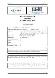
The sub-scenario is shown in the figure below.<br />
Relay<br />
Feeder-link<br />
B5f<br />
Relay<br />
Feeder-link<br />
B5f<br />
Masterstation<br />
Masterstation<br />
Interfering<br />
Feeder-link<br />
Relay<br />
BS<br />
Desired<br />
Feeder-link<br />
Relay<br />
Relay to MS:<br />
B1<br />
MS<br />
Relay to MS:<br />
B1<br />
MS<br />
MS<br />
Relay to<br />
MS: B1<br />
a b c<br />
Figure 2-3 B5f scenario for three cases: a) NLOS (OLOS) b) LOS c) Combined interference case.<br />
B5f scenario consists of the cases with relay antennas some meters over the roof-top or some meters<br />
below the roof-top. Critical information is, if the link is LOS or NLOS: It is possible to create LOS links<br />
with the antennas below roof-tops. As well it is possible to implement NLOS links with antennas above<br />
the average roof-top level. Our approach is that the desired BS to FRS links can be planned to be LOS or<br />
OLOS, or at least “good” links. It is assumed that the interfering links from undesired BS to FRS can be<br />
LOS or NLOS. (Although in practice this can be also affected by careful planning.) It should be pointed<br />
out that the link FRS to MS is covered by the model B1. Interference to undesired feeder link may occur.<br />
In B5f it is assumed that the relay station is shadowed due to some obstacle. The proposed model is based<br />
on literature and formed from the B5a LOS fixed relay model by attenuating artificially its direct<br />
component by 15 dB in average and summing to it a normally distributed random decibel number with<br />
standard deviation 8 dB. The path loss formula is based on the references [ZEA99] and [GEA03]. The<br />
other model parameters are the same as in B5a. The model B5f can also be understood as NLOS part of<br />
the model B5a.<br />
2.3.8 C1 – Suburban macro-cell<br />
In suburban macro-cells base stations are located well above the rooftops to allow wide area coverage,<br />
and mobile stations are outdoors at street level. Buildings are typically low residential detached houses<br />
with one or two floors, or blocks of flats with a few floors. Occasional open areas such as parks or<br />
playgrounds between the houses make the environment rather open. Streets do not form urban-like<br />
regular strict grid structure. Vegetation is modest.<br />
2.3.9 C2 – Urban macro-cell<br />
In typical urban macro-cell mobile station is located outdoors at street level and fixed base station clearly<br />
above surrounding building heights. As for propagation conditions, non- or obstructed line-of-sight is a<br />
common case, since street level is often reached by a single diffraction over the rooftop. The building<br />
blocks can form either a regular Manhattan type of grid, or have more irregular locations. Typical<br />
building heights in urban environments are over four floors. Buildings height and density in typical urban<br />
macro-cell are mostly homogenous.<br />
2.3.10 C3 – Bad urban macro-cell<br />
Bad urban environment describes cities with buildings with distinctly inhomogeneous heights or<br />
densities, and results to a clearly dispersive propagation environment in delay and angular domain. The<br />
inhomogeneties in city structure can be e.g. due to large water areas separating the built-up areas, or the<br />
high-rise skyscrapers in otherwise typical urban environment. Increased delay and angular dispersion can<br />
also be caused by mountains surrounding the city. Base station is typically located above the average<br />
rooftop level, but within its coverage range there can also be several high-rise buildings exceeding the<br />
base station height. From modelling point of view this differs from typical urban macro-cell by an<br />
additional far scatterer cluster.<br />
2.3.11 C4 – Urban macro outdoor to indoor<br />
The Outdoor-to-Indoor scenario is specified here as follows: The outdoor environment is the same as in<br />
urban macrocellular case, C2, and the indoor environment is the same as in indoor case, A1. The base<br />
station antenna is clearly above the mean building height. This means that there will be quite long LOS<br />
paths to the walls penetrated by the signals, mainly in the higher floors of the buildings. On the other hand<br />
there is often quite a severe shadowing, especially in the lower floors. The propagation in the<br />
macrocellular outdoor scenario is different from the corresponding microcellular case in that the outdoor<br />
Page 19 (82)