

Final report on link level and system level channel models - Winner
Final report on link level and system level channel models - Winner
Final report on link level and system level channel models - Winner

Create successful ePaper yourself
Turn your PDF publications into a flip-book with our unique Google optimized e-Paper software.
WINNER D5.4 v. 1.4<br />
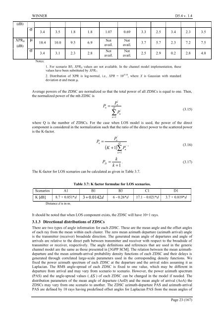
(dB)<br />
XPR H<br />
(dB)<br />
σ<br />
µ<br />
σ<br />
3.4 3.5 1.8 1.8 1.07 0.69 3.3 2.5 3.4 2.3 3.5<br />
10.4 10.0 9.5 6.9<br />
3.4 3.1 2.3 2.8<br />
Notes:<br />
Not<br />
avail.<br />
Not<br />
avail.<br />
Not<br />
avail.<br />
Not<br />
avail.<br />
3.7 5.7 2.3 7.2 7.5<br />
2.5 2.9 0.2 2.8 4.0<br />
1. For scenario B3, XPR H values are not available. In the <strong>channel</strong> model implementati<strong>on</strong>, these<br />
values have been substituted by XPR V .<br />
2. Distributi<strong>on</strong> of XPR is log-normal, i.e., XPR = 10 X/10 , where X is Gaussian with st<strong>and</strong>ard<br />
deviati<strong>on</strong> σ <strong>and</strong> mean µ.<br />
Average powers of the ZDSC are normalized so that the total power of all ZDSCs is equal to <strong>on</strong>e. Then,<br />
the normalized power of the nth ZDSC is<br />
P<br />
'<br />
n<br />
n<br />
= Q<br />
P<br />
∑<br />
n=<br />
1<br />
P<br />
'<br />
n<br />
(3.15)<br />
where Q is the number of ZDSCs. For the case when LOS model is used, the power of the direct<br />
comp<strong>on</strong>ent is c<strong>on</strong>sidered in the normalizati<strong>on</strong> such that the ratio of the direct power to the scattered power<br />
is the K-factor.<br />
'<br />
n<br />
n<br />
=<br />
Q<br />
P<br />
P<br />
( K + 1)∑<br />
n=<br />
1<br />
The K-factor for LOS scenarios can be calculated as given in Table 3.7.<br />
P<br />
'<br />
n<br />
, (3.16)<br />
k<br />
P D<br />
= . (3.17)<br />
k +1<br />
Table 3.7: K factor formulae for LOS scenarios.<br />
Scenarios A1 B1 B3 C1 D1<br />
K [dB] 8.7 + 0.051*d 3+ 0.0142d 6 - 0.26*d 17.1 – 0.021*d 3.7 + 0.019*d<br />
Distance d is in m.<br />
It should be noted that when LOS comp<strong>on</strong>ent exists, the ZDSC will have 10+1 rays.<br />
3.1.3 Directi<strong>on</strong>al distributi<strong>on</strong>s of ZDSCs<br />
There are two types of angle informati<strong>on</strong> for each ZDSC. These are the mean angle <strong>and</strong> the offset angles<br />
of each ray from the mean within each cluster. The zero mean azimuth departure (azimuth arrival) angle<br />
is the transmitter (receiver) broadside directi<strong>on</strong>. The generated mean angle of departures <strong>and</strong> angle of<br />
arrivals are relative to the direct path between transmitter <strong>and</strong> receiver with respect to the broadside of<br />
transmitter or receiver, respectively. The angle definiti<strong>on</strong>s <strong>and</strong> references that are used in the generic<br />
<strong>channel</strong> model are the same as those presented in [3GPP SCM]. The relati<strong>on</strong> between the mean azimuthdeparture<br />
<strong>and</strong> the mean azimuth-arrival probability density functi<strong>on</strong>s of each ZDSC <strong>and</strong> their delays is<br />
generated through correlated large-scale parameters used in the corresp<strong>on</strong>ding density functi<strong>on</strong>s. We<br />
fixed the power azimuth spectrum of each ZDSC at the departure <strong>and</strong> the arrival sides assuming it as<br />
Laplacian. The RMS angle-spread of each ZDSC is fixed to <strong>on</strong>e value, which may be different in<br />
departure from arrival <strong>and</strong> may vary from scenario to scenario. However, the power azimuth spectrum<br />
(PAS) <strong>and</strong> the angle-spread values (AS ) of each ZDSC can be changed in the model if needed. The<br />
distributi<strong>on</strong> parameters of the mean angle of departure (AoD) <strong>and</strong> the mean angle of arrival (AoA) the<br />
ZDSCs may vary from <strong>on</strong>e scenario to another. The ZDSC azimuth-departure PAS <strong>and</strong> azimuth-arrival<br />
PAS are defined by 10 rays having predefined offset angles for Laplacian PAS from the mean angles of<br />
Page 23 (167)


