

Final report on link level and system level channel models - Winner
Final report on link level and system level channel models - Winner
Final report on link level and system level channel models - Winner

You also want an ePaper? Increase the reach of your titles
YUMPU automatically turns print PDFs into web optimized ePapers that Google loves.
WINNER D5.4 v. 1.4<br />
periods. Path-loss will be determined according to the geometry, large-scale parameters correlate<br />
properly, but first-order bulk parameters change abruptly from a segment to segment. Thus, while there is<br />
<strong>on</strong>ly <strong>on</strong>e mobile stati<strong>on</strong> in the scenario, each locati<strong>on</strong> of the mobile <strong>on</strong> its path is assigned a unique label<br />
ms1 to msM. This is equivalent to a scenario with multiple mobile stati<strong>on</strong>s at different positi<strong>on</strong>s ms1 to<br />
msM. The resulting procedure is as follows.<br />
1. Set base stati<strong>on</strong> c1 <strong>and</strong> c2 locati<strong>on</strong>s <strong>and</strong> array orientati<strong>on</strong>s according to geometry.<br />
2. Set MS locati<strong>on</strong>s ms1 to msM <strong>and</strong> array orientati<strong>on</strong>s al<strong>on</strong>g the route. Choose the distance<br />
between adjacent locati<strong>on</strong>s according to desired accuracy.<br />
3. Set all the entries of the pairing matrix to 1.<br />
4. Generate all the radio <strong>link</strong>s at <strong>on</strong>ce obtain correct correlati<strong>on</strong> properties. It is possible to generate<br />
more <strong>channel</strong> realizati<strong>on</strong>s, i.e. time samples, for each <strong>channel</strong> segment afterwards. This can be<br />
d<strong>on</strong>e by applying the initial values of small scale parameters in the Table 6.5.<br />
5. Simulate <strong>channel</strong> segments c<strong>on</strong>secutively to emulate moti<strong>on</strong> al<strong>on</strong>g the route.<br />
6.3.2 Interference<br />
Interference situati<strong>on</strong>s are quite similar to h<strong>and</strong>over situati<strong>on</strong>s, except that in this case the sec<strong>on</strong>d BS<br />
transmits a n<strong>on</strong>-desired signal which creates interference. That doesn’t change the parameters of the<br />
<strong>channel</strong>. What changes, however, is the degree of realism that is needed for the interference <strong>channel</strong>. This<br />
has been discussed in Chapter 4.1.3.<br />
6.3.3 Multi-cell <strong>and</strong> multi-user<br />
The h<strong>and</strong>over <strong>and</strong> interference situati<strong>on</strong>s from the previous secti<strong>on</strong>s were an example of single-user<br />
multi-cell setups. Other cases of such a setup are for example found in the c<strong>on</strong>text of multi-BS protocols,<br />
where a MS receives data from multiple BS simultaneously.<br />
The extensi<strong>on</strong> to multiple users (<strong>and</strong> <strong>on</strong>e or more base stati<strong>on</strong>s) is straightforward. Because locati<strong>on</strong> <strong>and</strong><br />
mobile stati<strong>on</strong> index are treated equivalently, it follows that all locati<strong>on</strong>s of all mobiles have to be<br />
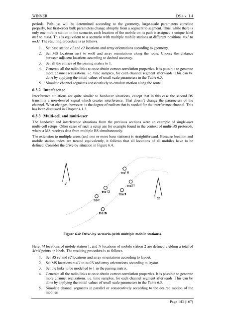
defined. C<strong>on</strong>sider the drive-by situati<strong>on</strong> in Figure 6.4.<br />
Figure 6.4: Drive-by scenario (with multiple mobile stati<strong>on</strong>s).<br />
Here, M locati<strong>on</strong>s of mobile stati<strong>on</strong> 1, <strong>and</strong> N locati<strong>on</strong>s of mobile stati<strong>on</strong> 2 are defined yielding a total of<br />
M+N points or labels. The resulting procedure is as follows.<br />
1. Set BS c1 <strong>and</strong> c2 locati<strong>on</strong>s <strong>and</strong> array orientati<strong>on</strong>s according to layout.<br />
2. Set MS locati<strong>on</strong>s ms11 to ms2N <strong>and</strong> array orientati<strong>on</strong>s according to layout.<br />
3. Set the <strong>link</strong>s to be modelled to 1 in the pairing matrix.<br />
4. Generate all the radio <strong>link</strong>s at <strong>on</strong>ce obtain correct correlati<strong>on</strong> properties. It is possible to generate<br />
more <strong>channel</strong> realizati<strong>on</strong>s, i.e. time samples, for each <strong>channel</strong> segment afterwards. This can be<br />
d<strong>on</strong>e by applying the initial values of small scale parameters in the Table 6.5.<br />
5. Simulate <strong>channel</strong> segments in parallel or c<strong>on</strong>secutively according to the desired moti<strong>on</strong> of the<br />
mobiles.<br />
Page 143 (167)


