Tideflex Mixing System Catalog - RM Headlee
Tideflex Mixing System Catalog - RM Headlee
Tideflex Mixing System Catalog - RM Headlee

Create successful ePaper yourself
Turn your PDF publications into a flip-book with our unique Google optimized e-Paper software.
ideflex<br />
MIXING SYSTEM<br />
FOR FINISHED WATER STORAGE FACILITIES
Red Valve<br />
<strong>Tideflex</strong> ® in<br />
Drinking Water<br />
Reservoirs<br />
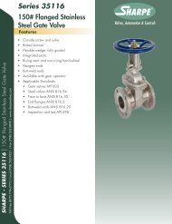
Eliminate Stagnation<br />
Figure 1 — Problem<br />
@@@@ €€€€ ÀÀÀÀ ,,,, yyyy<br />
@@@@ €€€€ ÀÀÀÀ ,,,, yyyy<br />
Stagnant<br />
Water<br />
Figure 2 — Solution<br />
@@@@ €€€€ ÀÀÀÀ ,,,, yyyy<br />
@@@@ €€€€ ÀÀÀÀ ,,,, yyyy<br />
Red Valve CFD Modeling will demonstrate<br />
the fluid dynamics of the system.<br />
@@@@ €€€€ ÀÀÀÀ ,,,, yyyy<br />
@@@@ €€€€ ÀÀÀÀ ,,,, yyyy<br />
@@@@ €€€€ ÀÀÀÀ ,,,, yyyy<br />
@@@@ €€€€ ÀÀÀÀ ,,,, yyyy<br />
@@@@ €€€€ ÀÀÀÀ ,,,, yyyy<br />
TIDEFLEX ®<br />
MIXING SYSTEM<br />
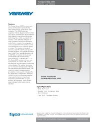
Finished water storage reservoirs have<br />
always had to contend with deterioration<br />
of water quality. Many reservoirs were<br />
designed solely to supply the required<br />
hydraulics of the distribution system, not<br />
necessarily to maintain water quality<br />
within the reservoir itself. The most common<br />
problem in reservoirs is the loss of<br />
chlorine or chloramine residual resulting<br />
from hydraulic short circuiting, poor mixing<br />
and circulation, poor turnover rate<br />
and excessive detention time. Stagnation<br />
and “dead spots” can lead to serious<br />
water quality issues such as the formation<br />
and multiplication of bacteria.<br />
Reservoirs can be circular, rectangular or<br />
irregularly shaped with capacities from a<br />
few hundred gallons to 50 million gallons<br />
or more. Many of these reservoirs are<br />
designed with common inlet/outlets or inlets<br />
and outlets that are within close proximity<br />
to one another. In this case, water close to<br />
the inlet and outlet is turned over and has<br />
adequate residual, but hydraulic short circuiting<br />
leads to stagnation and dead spots<br />
outside the inlet/outlet area of influence.<br />
See Figure 1.<br />
The <strong>Tideflex</strong> ® <strong>Mixing</strong> <strong>System</strong> (TMS) was<br />
developed to eliminate stagnation and dead<br />
spots by preventing hydraulic short circuiting,<br />
improving mixing and circulation and<br />
optimizing turnover rate and detention<br />
time. See Figure 2.<br />
The TMS is comprised of a manifold<br />
system with two sets of <strong>Tideflex</strong> ® Check<br />
Valves. One set is used to fill the reservoir,<br />
and the second set is used to drain the<br />
reservoir. <strong>Tideflex</strong> ® valves are completely<br />
manufactured of NSF-61-approved elastomers.<br />
The valves are passive, have no<br />
mechanical parts and require only differential<br />
head to operate — no outside energy<br />
source is needed. The <strong>Tideflex</strong> ® , coupled<br />
with PVC, stainless steel, ductile iron or<br />
any other suitable pipe material, creates<br />
an effective mixing system that requires<br />
no additional equipment and requires little<br />
or no maintenance.<br />
DESIGN ADVANTAGES<br />
The TMS <strong>System</strong> can be installed in new<br />
or existing reservoirs without the need to<br />
modify the structure — no excavation and<br />
no taps into the reservoir. The TMS is<br />
simply connected to a single inlet/outlet<br />
on one side of the tank.<br />
The entire TMS operates on differential<br />
pressure. The key is, this differential<br />
pressure is already in place and is used<br />
to fill and drain the reservoir. Compared<br />
to submersible mixers with high capital<br />
costs and high energy consumption, the<br />
TMS is very cost effective.<br />
Engineered rubber check sleeves have memory:<br />
forward hydraulic pressure opens valve,<br />
and reverse pressure seals the valve and prevents<br />
backflow.<br />
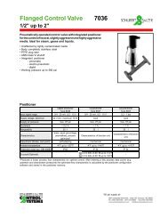
Jet Velocity<br />
Jet Velocity vs. Flow<br />
TIDEFLEX<br />
Fixed Orifice<br />
Flow<br />
<strong>Tideflex</strong> variable orifice enhances jet velocity<br />
at all fill rates, optimizing mixing.
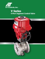
TIDEFLEX ® MIXING<br />
SYSTEM (TMS)<br />
● Eliminates short circuiting,<br />
stagnation, and “dead zones.”<br />
● Minimizes the amount of pipe and<br />
fittings required for a separate inlet<br />
and outlet.<br />
City of Antioch, Calif. —<br />
3MG ground level steel<br />
reservoir, (2) 12" Series 35 for<br />
filling reservoir and mixing.<br />
(3) 4" Series 35 for mid-tank mixing.<br />
● Improves mixing and circulation.<br />
● Improves turnover rate.<br />
● Utilizes the variable orifice of the<br />
<strong>Tideflex</strong> ® valve to maximize jet velocity<br />
and mixing at all flow rates.<br />
● Can be used with recirculation and<br />
rechlorination systems.<br />
● Uses <strong>Tideflex</strong> ® valves fabricated from<br />
NSF-61-approved elastomers.<br />
● Operates on differential pressure; no<br />
external energy source required.<br />
● Can be designed for new and retrofit<br />
applications, standpipes and elevated<br />
tanks.<br />
● Flanged, slip-on or custom<br />
configuration. <strong>System</strong>s 1/8"-96".<br />
Typical <strong>Tideflex</strong> ® manifold<br />
in circular above ground<br />
storage tanks.<br />
PROVEN<br />
PERFO<strong>RM</strong>ANCE ON:<br />
● Circular reservoirs.<br />
● Rectangular reservoirs.<br />
● Elevated storage tanks.<br />
● Standpipes.
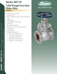
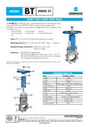
OPERATION OF TMS RECTANGULAR RESERVOIRS<br />
The <strong>Tideflex</strong> ® <strong>Mixing</strong> <strong>System</strong> was designed<br />
to be simple, reliable and cost effective.<br />
The system makes use of the patented<br />
<strong>Tideflex</strong> ® Check Valve and a simple piping<br />
manifold. This reduces cost by minimizing<br />
the amount of pipe and fittings required for<br />
a separate inlet and outlet. By discharging<br />
water from one side of the reservoir and<br />
draining from the other, the system ensures<br />
that the water supply is constantly “turned<br />
over” to avoid stagnation and dead zones.<br />
The mixing system works in two phases.<br />
When the reservoir is being filled<br />
(Figure 2a), the pressure of the water in<br />
the manifold forces the TF-2 or Series 35<br />
“discharge” valves to open, and holds the<br />
Series 37 “drain” valves closed on the<br />
opposite side. When the reservoir is<br />
drained (Figure 2b), the head pressure<br />
above the manifold holds the discharge<br />
valves closed and forces the drain valves<br />
to open. This two-stage system ensures<br />
that the water is continually cycled.<br />
Figure 2<br />
,,<br />
,,,<br />
,<br />
,,<br />
,,<br />
,,<br />
,,<br />
(a) Filling Sequence<br />
The simplicity of the system makes it<br />
reliable, with no moving parts, electric<br />
motors, bearings or seals to maintain.<br />
There is no additional energy consumption<br />
and no equipment exposed to the<br />
elements. The system can be fitted as part<br />
of a new construction or easily retrofitted<br />
to an existing reservoir.<br />
12" TF-2 discharging.<br />
(b) Draining Sequence<br />
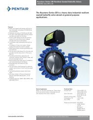
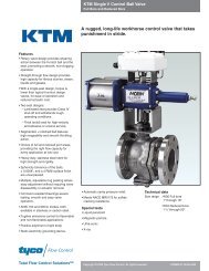
OPERATION OF TMS CIRCULAR RESERVOIRS<br />
In circular reservoirs, a manifold pipe is<br />
extended across the reservoir to the far<br />
side. On the far side, TF-2 or Series 35<br />
Check Valves are installed that open during<br />
filling of the reservoir and are closed during<br />
draining of the tank (Figure 3a).<br />
<strong>Tideflex</strong> ® Check Valve is a variable orifice<br />
which discharges a high-momentum jet<br />
compared to open-ended pipes. Also,<br />
<strong>Tideflex</strong> ® valves discharge an elliptically<br />
shaped jet, not circular. The elliptical jet<br />
creates a strong sheer plane which also<br />
improves the mixing.<br />
Since the reservoir is circular, the highmomentum<br />
jets discharged from the<br />
<strong>Tideflex</strong> ® create turbulence that is carried<br />
around the circumference and across the<br />
entire cross section of the tank.<br />
Draining is accomplished from the near<br />
side of the reservoir where the pipe enters.<br />
On this side, a “tee” is installed whereby<br />
multiple Series 37 <strong>Tideflex</strong> ® valves are<br />
installed. These valves are closed during<br />
filling of the tank and open during draining<br />
of the tank (Figure 3b).<br />
Figure 3<br />
,,, ,,,<br />
,,, ,,,<br />
,,, ,,,<br />
,,, ,,,<br />
,,, ,,,<br />
(a) Filling Sequence<br />
Figures shown are general representations.<br />
Custom designs are required for<br />
individual reservoirs based on tank<br />
design and operating conditions.<br />
(2) 16" Series 37 as drain valves.<br />
(b) Draining Sequence
STANDPIPES AND ELEVATED STORAGE TANKS<br />
Standpipes and elevated storage tanks also<br />
have potential problems with stagnation<br />
when they are filled and drained from a<br />
single location. Red Valve designs custom<br />
mixing arrangements for elevated storage<br />
tanks.<br />
A TMS system can be supplied with conventional<br />
pipe materials, or it can be completely<br />
fabricated of wire-reinforced rubber<br />
similar to the construction of a truck<br />
tire. The rubber option is extremely useful<br />
in regions where freezing is a concern. Ice<br />
can easily damage plastic or even metal<br />
pipe. An all-rubber TMS remains flexible<br />
and cannot be damaged.<br />
Stagnant Water<br />
Mixed Water<br />
,,, ,,,<br />
,,, ,,,<br />
,,, ,,,<br />
,,, ,,,<br />
,,, ,,,<br />
,,, ,,,<br />
,,, ,,,<br />
Stagnant<br />
Water<br />
Mixed Water<br />
,,, ,,,<br />
,,, ,,,<br />
,,, ,,,<br />
,,, ,,,<br />
,,, ,,,<br />
Custom “T” configuration for tank mixing.<br />
TANK OVERFLOW PROTECTION<br />
<strong>Tideflex</strong> ® valves are installed on overflow<br />
pipes to prevent birds, insects and rodents<br />
from entering the storage tank and contaminating<br />
the water supply.<br />
The <strong>Tideflex</strong> ® all-rubber construction will<br />
not freeze, ensuring proper operation in all<br />
climates, including sub-zero temperatures.<br />
Conventional flapgate valves have a history<br />
of freezing in the open or closed position<br />
due to temperature and/or corrosion, and<br />
they cannot be mounted in a vertical pipe<br />
without the aid of a spring.<br />
The <strong>Tideflex</strong> ® valve can also be supplied<br />
with an integral proximity switch to signal<br />
overflow events. The switch can be easily<br />
incorporated into SCADA systems.
<strong>Tideflex</strong> ® Discharge<br />
100% elastomer construction eliminates maintenance<br />
Will not warp or freeze open or shut<br />
Custom-built to customer specifications<br />
Lowest headloss<br />
No springs or moving parts<br />
Will not rust or corrode<br />
Materials of Construction<br />
NSF-61-approved elastomer<br />
Stainless steel retaining ring or mounting band<br />
Two discharge valve options are available<br />
for the TMS: the <strong>Tideflex</strong> ® TF-2 Slip-On<br />
Check Valve and the Series 35 Flanged<br />
Check Valve. Both offer extremely low<br />
headloss to keep pumping costs at a minimum.<br />
Both offer all-rubber construction<br />
for unsurpassed corrosion protection,<br />
resistance to freezing and maximum<br />
service life.<br />
TF-2<br />
The TF-2 is designed to slip onto the end of the discharge ports.<br />
The cuff of the TF-2 is constructed to exactly match the outside<br />
diameter of the pipe. Solid stainless steel bands are provided to<br />
secure the valve to the pipe. Additional pins can be installed for<br />
added security.<br />
The Series 35 is provided with an integral flange, constructed entirely<br />
of rubber so no additional gaskets are required. Stainless steel<br />
backup rings are provided for a secure connection. The flange of the<br />
Series 35 can be drilled to ANSI or metric specifications, and special<br />
oversized and square flanges are available for retrofit applications.<br />
Series 35<br />
L<br />
L<br />
F<br />
H<br />
A<br />
H<br />
Series 35<br />
TF-2<br />
C<br />
FLANGE SIZE FLANGE O.D. LENGTH BILL HEIGHT<br />
(ANSI)* (F) (L) (H)<br />
PIPE O.D.* LENGTH BILL HEIGHT CUFF LENGTH<br />
(A) (L) (H) (C)<br />
1 3 1/2 2 1/2 1 1/2<br />
1 1/2 5 6 3<br />
2 6 6 4<br />
2 1/2 7 8 5<br />
3 7 1/2 9 5 1/2<br />
4 9 12 7<br />
5 10 15 1/2 9<br />
6 11 16 10 1/2<br />
8 13 1/2 16 1/2 13<br />
10 16 21 1/2 17<br />
12 19 26 1/2 20 1/2<br />
14 21 26 22<br />
16 23 1/2 26 27<br />
18 25 30 29<br />
20 27 1/2 33 33<br />
22 29 1/2 36 33<br />
24 32 39 37<br />
30 38 3/4 42 50<br />
3/4 3 1 1/2 1<br />
1 3 1 1/2 1<br />
1 1/2 6 3 1<br />
2 6 4 1<br />
2 1/2 8 5 1<br />
3 9 5 1/2 1 1/2<br />
4 12 7 1 1/2<br />
5 15 1/2 9 2<br />
6 16 10 1/2 2<br />
8 16 1/2 13 2<br />
10 21 1/2 17 3<br />
12 26 1/2 20 1/2 4 1/2<br />
14 26 22 4<br />
16 26 27 5<br />
18 30 29 6<br />
20 33 33 8<br />
22 36 33 8<br />
24 39 37 8<br />
* Larger pipe sizes available to 96". * Larger pipe sizes available to 96".<br />
Numbers indicate maximum dimensions in inches.<br />
Numbers indicate maximum dimensions in inches.
<strong>Tideflex</strong> ® Drain<br />
Features unique maintenance-free, one-piece elastomer<br />
check-sleeve design<br />
ANSI Class 125 Flanges, DIN PN6, PN10, PN16<br />
100% elastomer construction<br />
Will not rust or corrode<br />
Will not warp or freeze open or shut<br />
Materials of Construction<br />
NSF-61-approved elastomer<br />
Stainless steel retaining ring<br />
The drain valve of the TMS is the Series 37 Inline Check Valve.<br />
The Series 37 features all-rubber construction, no moving parts<br />
and the patented <strong>Tideflex</strong> ® “duckbill” design for maximum backflow<br />
prevention.<br />
The bill of this valve is designed to slip inside of the drain port,<br />
secured by an integral flange. Stainless steel backup rings are provided<br />
to complete the installation. The flange can be drilled to ANSI<br />
or metric specifications.<br />
The pressure drop of the Series 37 is increased due to the smaller<br />
inside diameter required to fit the valve inside of the pipe. Red<br />
Valve recommends increasing the diameter of the drain ports to<br />
compensate.<br />
Series 37<br />
F<br />
H<br />
Series 37<br />
L<br />
PIPE I.D.* BILL HEIGHT LENGTH FLANGE O.D.<br />
(H) (L) (F)<br />
Flow<br />
2 1 7/8 4 3/4 6<br />
3 2 7/8 5 3/8 7 1/2<br />
4 3 7/8 7 1/8 9<br />
6 5 7/8 11 11<br />
8 7 7/8 12 1/4 13 1/2<br />
10 9 7/8 15 1/4 16<br />
12 11 7/8 18 1/4 19<br />
14 13 3/4 21 1/2 21<br />
16 15 3/4 22 3/4 23 1/2<br />
18 17 3/4 23 3/4 25<br />
20 19 3/4 31 3/4 27 1/2<br />
24 23 3/4 37 32<br />
30 29 3/4 40 1/4 38 3/4<br />
* Larger sizes available upon request; actual pipe I.D. must be specified for<br />
proper fit. Numbers indicate maximum dimension.
700 North Bell Avenue, Pittsburgh, PA 15106 PHONE: 412/279-0044<br />
FAX: 412/279-7878<br />
www.redvalve.com<br />
The information presented in this catalog is<br />
provided in good faith. Red Valve Company,<br />
Inc., reserves the right to modify or improve<br />
its design specifications without notice and<br />
does not imply any guarantee or warranty<br />
for any of its products from reliance upon<br />
the information contained herein. All orders<br />
are subject to Red Valve’s standard terms<br />
and warranty and are subject to final<br />
acceptance by Red Valve.<br />
Viton® and Hypalon® are registered<br />
trademarks of DuPont Dow Elastomers.<br />
Teflon® is a registered trademark of the<br />
DuPont Company. Redflex®, <strong>Tideflex</strong>®,<br />
Red Valve and the Red Valve “rv” logo<br />
are registered trademarks of Red Valve<br />
Company, Inc.<br />
Red Valve <strong>Tideflex</strong>® Check Valves<br />
are patented, 6016,839 / 5,727,593 /<br />
5 606 995 / 4585,031<br />
© Red Valve Company, 2000, All Rights<br />
Reserved. Red Valve is a registered<br />
trademark of the Red Valve Company, Inc.<br />
RECYCLABLE<br />
PAPER<br />
RVTMS-7789 6/2000 5M
3D COMPUTATIONAL FLUID<br />
DYNAMIC MODELING (CFD)<br />
The Red Valve engineering team can provide charts<br />
with manifold design and CFD Modeling for <strong>Tideflex</strong> ®<br />
<strong>Mixing</strong> <strong>System</strong>s. The modeling will reveal the limitation<br />
of the existing system and demonstrate the<br />
mixing dynamics.<br />
Feature particle tracks showing overall flow<br />
pattern of reservoir<br />
Contain plots of velocity and pressure distribution<br />
Velocity vector plots show the direction and<br />
magnitude of flow<br />
<strong>Tideflex</strong> ® Product Line<br />
Check Valves<br />
Maintenance-free design<br />
Seal around debris<br />
Long service life<br />
Effluent Diffusers<br />
Prevent intrusion of debris<br />
Increase initial dilution<br />
Maintain peak performance<br />
Air Diffusers<br />
Non clogging designs<br />
Fine or coarse bubble<br />
Improve mixing action<br />
Are you currently designing a reservoir<br />
project?<br />
□<br />
Reservoir — New<br />
□<br />
Reservoir — Retrofit<br />
□ Standpipe<br />
□<br />
Elevated Storage Tank<br />
□<br />
Name<br />
Title<br />
Have a local representative contact me.<br />
Company<br />
Address<br />
City State Zip<br />
Phone<br />