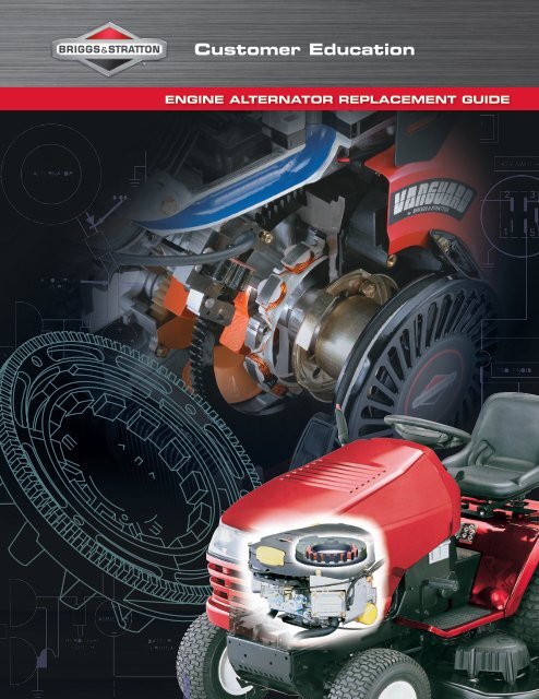
ENGINE ALTERNATOR REPLACEMENT GUIDE - Briggs & Stratton
ENGINE ALTERNATOR REPLACEMENT GUIDE - Briggs & Stratton
ENGINE ALTERNATOR REPLACEMENT GUIDE - Briggs & Stratton

You also want an ePaper? Increase the reach of your titles
YUMPU automatically turns print PDFs into web optimized ePapers that Google loves.
<strong>ENGINE</strong> <strong>ALTERNATOR</strong> <strong>REPLACEMENT</strong> <strong>GUIDE</strong>
ThePowerPortal.com<br />
Your “One Stop” Information Source<br />
<strong>Briggs</strong> & <strong>Stratton</strong> has developed a powerful and flexible private web-based<br />
portal for its family of products, ThePowerPortal.com.<br />
Power Portal Features<br />
➤ Secure, on-demand, 24x7 access to meaningful information and functions for<br />
all of our products.<br />
➤ Role-based security that will dynamically generate an interface and content<br />
which is specific to the various roles of the user.<br />
➤ Interact via the internet for a variety of business transactions.<br />
➤ Here is a glimpse of the available features on the brands for which you provide<br />
sales and/or service for.<br />
• Brand specific product registration & rebate submission<br />
• Eclaim - electronic warranty claim filing for engines and<br />
end products<br />
• E-parts - service parts and/or whole goods look-up<br />
and ordering<br />
• Tech press search<br />
• Re-powering and replacement engine look-up<br />
• 1,000s of technical and service documents<br />
Use <strong>Briggs</strong> & <strong>Stratton</strong> Genuine Parts<br />
<strong>Briggs</strong> & <strong>Stratton</strong> engine warranty does not cover engine damage caused by<br />
non-original parts. <strong>Briggs</strong> & <strong>Stratton</strong> recommends the use of genuine <strong>Briggs</strong> &<br />
<strong>Stratton</strong> parts for warranty claims.<br />
• Identical genuine parts are used in<br />
manufacturing <strong>Briggs</strong> & <strong>Stratton</strong><br />
engines<br />
• Genuine parts are engineered and<br />
tested for exact fit and performance<br />
• 1-year limited warranty on original<br />
parts (USA-Canada Only)
Table of Contents<br />
Continuity Checks ‐ Switches ..................................................................................................................... 2<br />
DC Voltage Battery Test V .......................................................................................................................... 2<br />
Resistance Checks ...................................................................................................................................... 2<br />
Diode Checks ......................................................................................................................................... 3<br />
DC Shunt........................................................................................................................................................ 4<br />
How Does A Shunt Work?............................................................................................................................... 4<br />
Ohm's Law Formula........................................................................................................................................ 5<br />
DC Shunt Instructions..................................................................................................................................... 7<br />
No‐Load Starter Current Draw 12 Volt Starter Motors 300mV ..................................................................... 8<br />
Starter Current Draw – 12 Volt Starter Motors 300mV ............................................................................ 9<br />
AC Voltage Output Check v ...................................................................................................................... 10<br />
DC Amperage Output Check ..................................................................................................................11<br />
Checking DC Amperage Output.................................................................................................................... 12<br />
16 & 20 Amp Regulated Alternator................................................................................................................ 12<br />
Starter Motor Current Draw 120 Volt Starter Motors A .............................................................................. 13<br />
Electric Starter Kits Quick Reference............................................................................................................ 14<br />
Alternator Identification................................................................................................................................. 15<br />
Engine/Alternator Replacement Information................................................................................................. 17<br />
Replacing <strong>Briggs</strong> & <strong>Stratton</strong> Engines............................................................................................................ 17<br />
<strong>Briggs</strong> & <strong>Stratton</strong> Engine Replacing Engine Of Another Manufacturer......................................................... 21<br />
Performance Control Electronic Governor................................................................................................ 40<br />
AWG Wire Sizes........................................................................................................................................... 41<br />
Metric Wire Gauges...................................................................................................................................... 41<br />
Load Carrying Capacities.............................................................................................................................. 41<br />
Glossary of Terms......................................................................................................................................... 44<br />
1
CONTINUITY CHECKS ‐ SWITCHES<br />
1. Insert RED test lead into v receptacle in<br />
meter.<br />
2. Insert BLACK test lead into COM receptacle in<br />
meter.<br />
3. Rotate selector to position.<br />
4. When meter test leads are attached to switch<br />
terminals and switch is in “ON” position, a<br />
continuous tone indicates continuity. With<br />
switch in “OFF” position, no tone indicates no<br />
continuity (incomplete circuit). An incomplete<br />
circuit will be displayed as “OL”.<br />
PUSH BUTTON<br />
SWITCH<br />
(ELECTRIC<br />
START)<br />
IGNITION<br />
STOP SWITCH<br />
ROTARY<br />
KEY SWITCH<br />
TOGGLE SWITCH<br />
Continuity Checks<br />
DC VOLTAGE BATTERY TEST V<br />
1. Insert RED test lead into v receptacle in<br />
meter.<br />
2. Insert BLACK test lead into COM receptacle in<br />
meter.<br />
3. Rotate selector to V position.<br />
4. Connect RED test lead to + (positive) terminal<br />
on battery and BLACK test lead to - (negative)<br />
terminal. Battery voltage can be checked as<br />
shown.<br />
LEAD<br />
LEAD<br />
Battery posts, terminals and related accessories<br />
contain lead and lead compounds, chemicals<br />
known to the State of California to cause cancer<br />
and birth defects or other reproductive harm.<br />
WASH HANDS AFTER HANDLING.<br />
DC Voltage Battery Test<br />
RESISTANCE CHECKS<br />
1. Insert RED test lead into v receptacle in<br />
meter.<br />
2. Insert BLACK test lead into COM receptacle in<br />
meter.<br />
3. Rotate selector to position.<br />
4. Attach test leads to component being tested.<br />
5. Meter will display amount of ohms resistance in<br />
component being tested.<br />
TYPICAL 1 OHM RESISTOR<br />
FOR TRI-CIRCUIT <strong>ALTERNATOR</strong><br />
2<br />
Resistance Checks
DIODE CHECKS<br />
In the Diode Test position, the meter will display<br />
the forward voltage drop across the diode(s). If<br />
the voltage drop is less than 0.7 volt, the meter will<br />
“beep” once, as well as display the voltage drop. A<br />
continuous tone indicates continuity (shorted diode).<br />
An incomplete circuit (open diode) will be displayed<br />
as “OL”.<br />
TEST<br />
LEAD FROM<br />
METER<br />
TEST<br />
LEAD FROM<br />
METER<br />
1. Insert RED test lead into v receptacle in<br />
meter.<br />
2. Insert BLACK test lead into COM receptacle in<br />
meter.<br />
3. Rotate selector to position.<br />
4. Attach RED test lead to point “A” and BLACK test<br />
lead to point “B”. (It may be necessary to pierce<br />
wire with a pin as shown.)<br />
a. If meter “beeps” once, diode is OK.<br />
b. If meter makes a continuous tone, diode is<br />
defective (shorted).<br />
c. If meter displays “OL”, proceed to step 5.<br />
5. Reverse test leads.<br />
a. If meter “beeps” once, diode is installed<br />
backwards.<br />
b. If meter still displays “OL”, diode is defective<br />
(open).<br />
TEST<br />
LEAD FROM<br />
METER<br />
“BUMP” ON<br />
CONNECTOR<br />
INDICATES<br />
DIODE SIDE<br />
3 Amp DC<br />
B<br />
A<br />
B<br />
CONNECTOR DIODE<br />
WIRE<br />
FROM STATOR<br />
A<br />
TEST<br />
LEAD FROM<br />
METER<br />
CONNECTOR<br />
DIODE<br />
WIRE<br />
FROM STATOR<br />
Dual Circuit – Charging Unit<br />
TEST<br />
LEAD FROM<br />
METER<br />
TEST<br />
LEAD FROM<br />
METER<br />
WIRE<br />
FOR CHARGING<br />
CIRCUIT<br />
TEST<br />
LEAD FROM<br />
METER<br />
B<br />
DIODE<br />
A<br />
TEST<br />
LEAD FROM<br />
METER<br />
A<br />
DIODE<br />
B<br />
WIRE<br />
FOR LIGHTING<br />
CIRCUIT<br />
Tri-Circuit – Charging Circuit<br />
3<br />
Tri-Circuit – Lighting Circuit
RED Test Lead BLACK Test Lead Beep<br />
B A Yes<br />
C B Yes<br />
C D Yes<br />
D A Yes<br />
NOTE: Metal cased rectifiers must also be tested<br />
for “grounds”, as follows:<br />
With BLACK test lead probe contacting rectifier<br />
case, touch each terminal, A – D, with RED test lead<br />
probe. Meter should display “OL” at each terminal.<br />
If meter makes a continuous tone at any terminal,<br />
rectifier is defective (“grounded”).<br />
A<br />
D<br />
B<br />
C<br />
120 Volt Rectifier<br />
DC SHUNT<br />
Have you ever wanted one tool in your toolbox that<br />
would make your life so much easier that it would<br />
pay for itself after the first couple of uses? That tool<br />
might well be the 19359 DC shunt. The DC shunt<br />
is a device that enables the technician to make<br />
several electrical tests with only one hook-up to the<br />
equipment. By using the DC shunt, we can test for<br />
system draw with the key switch off, system draw<br />
with the key switch on, starter peak amp and steady<br />
amp draw, and alternator charging. All of these tests<br />
can be done in about 30 seconds taking all the guess<br />
work out of the process.<br />
Electricity is one of those mysterious entities that<br />
most of us are at best, very leery of or at worst,<br />
down right frightened of. But once we have a basic<br />
understanding of electrical theory, and acknowledge<br />
that electricity has to follow strict physical properties,<br />
electrical testing becomes one of the easiest<br />
troubleshooting problems we will encounter.<br />
How Does A Shunt Work?<br />
Several years ago we introduced the 19359 DC Shunt as a complement to the Fluke Digital Multi-meter.<br />
Though a very effective and useful tool, two questions usually come up:<br />
Why is a reading taken in millivolts to read amperage?<br />
Can I use the shunt with another brand of meter?<br />
The shunt works by adding a measured load (resistance) to a DC series circuit. Any load in a circuit will cause<br />
a voltage drop across that particular part of the total load. The two meter connecting posts are across part of<br />
the total load. The load in this case is the resistance to the flow of electrons through the shunt body between<br />
the posts. The meter must be set to the millivolt scale in order to obtain the correct reading. This is actually<br />
a much safer approach than working with higher amperage.<br />
4
FOR BLACK LEAD<br />
FROM METER<br />
RESISTANCE<br />
SECTION<br />
FOR RED LEAD<br />
FROM METER<br />
CONNECTS TO<br />
NEGATIVE BATTERY<br />
CABLE<br />
CONNECTS TO<br />
NEGATIVE BATTERY<br />
POST<br />
Previous Style<br />
Current Style<br />
Note: Meter and battery connections to shunt are the same as the previous DC shunt as shown above.<br />
OHM'S LAW FORMULA<br />
Some background information may help to make this clearer. Ohm’s Law states that 1 volt of electrical pressure<br />
is required to move 1 amp of current (electron flow) through 1 ohm of resistance. Expressed mathematically,<br />
E=IxR or volts equals amps multiplied by resistance.<br />
1 volt = 1 amp x 1 ohm<br />
The DC shunt is designed to have a predetermined resistance of 0.001 ohm between the meter connection<br />
posts. When we use the shunt to check the alternator charge rate, amps is the unknown. Changing Ohm’s<br />
Law around to determine the current gives us:<br />
1 volt<br />
1 amp = ---------<br />
1 ohm<br />
Let’s take a look at units of measure. The prefix “milli” is Latin for 1/1000 of a unit. For example, 0.001 inch<br />
could be called a milliinch. Therefore, 1/1000 of an amp equals 0.001 amp or one milliamp. Also, one millivolt<br />
is 1/1000th of a volt or 0.001 volt. Applying these units of measurement for <strong>Briggs</strong> & <strong>Stratton</strong> shunt into Ohm’s<br />
Law gives us:<br />
1 millivolt 0.001 volt<br />
1 amp = ----------------- = -----------------<br />
1 milliohm 0.001 ohm<br />
The above equation shows that across the posts on the <strong>Briggs</strong> & <strong>Stratton</strong> shunt, 1 milliohm equals 1 amp of<br />
current flowing in the circuit. This is why the test meter is set to the millivolt range.<br />
5
Now, let’s add charging current from the alternator system flowing through the shunt. Resistance through the<br />
shunt will stay the same. We know the current will change. Since the shunt measures voltage drop, we have<br />
to be interested in the voltage or pressure in the system. The resistance value of the shunt is set so that we<br />
know there is a 1 to 1 ratio between amps and millivolts. Therefore, a reading of 2 millivolts on the meter face<br />
is equal to 2 amps of current, 3 equals 3, etc.<br />
From this discussion, it should be clear that any meter capable of reading millivolts can be used with the DC<br />
shunt.<br />
6
DC SHUNT INSTRUCTIONS<br />
The DC shunt, part number 19468 readily adapts<br />
to standard mount, side mount or tab type battery<br />
terminals. The shunt must be installed on the<br />
- (negative) terminal of the battery.<br />
For standard terminals, attach ring terminal on shunt<br />
to post terminal on battery. For tab terminal batteries,<br />
attach shunt to battery terminal using 1/4" – 20 stud<br />
and wing nut. For side terminal batteries, remove<br />
post terminal from shunt and thread into side terminal<br />
on battery. Attach battery cable to shunt using<br />
3/8" – 16 nut from post terminal.<br />
The Digital Multimeter will withstand DC input of<br />
10 – 20 Amps for up to 30 seconds. To avoid blowing<br />
fuse in meter, use the DC shunt when checking<br />
current draw of 12 volt starter motors or DC output<br />
on 16 Amp regulated alternator.<br />
Charging output can be checked with the engine<br />
running. All connections must be clean and tight for<br />
correct amperage readings.<br />
1. Install shunt on negative battery terminal.<br />
LEAD<br />
LEAD<br />
NEGATIVE<br />
BATTERY<br />
TERMINAL<br />
2. Insert RED test lead into v receptacle in<br />
meter and RED receptacle on shunt.<br />
3. Insert BLACK test lead into COM receptacle in<br />
meter and BLACK receptacle on shunt.<br />
4. Rotate selector switch to 300mV position.<br />
ATTACH NEGATIVE<br />
BATTERY CABLE<br />
NEGATIVE BATTERY<br />
TERMINAL<br />
ATTACH NEGATIVE<br />
BATTERY CABLE<br />
NEGATIVE BATTERY<br />
TERMINAL<br />
ATTACH<br />
NEGATIVE<br />
BATTERY<br />
CABLE WITH<br />
3/8"-16 NUT<br />
NEGATIVE BATTERY<br />
TERMINAL<br />
Standard Mount Tab Mount Side Mount<br />
7
NO‐LOAD STARTER CURRENT DRAW<br />
12 VOLT STARTER MOTORS 300mV<br />
(STARTER MOTOR REMOVED FROM <strong>ENGINE</strong>)<br />
To check the no-load amperage draw of a 12 volt<br />
starter motor that is removed from the engine, a<br />
fixture as shown in the figure should be used. See<br />
the diagram for the parts necessary to make a test<br />
set-up.<br />
PRESS TO<br />
START<br />
TEST<br />
LEAD FROM<br />
METER<br />
TEST LEAD<br />
FROM<br />
METER<br />
CAUTION: DO NOT clamp motor housing<br />
in a vise. Starter motors contain two ceramic<br />
magnets which can be broken or cracked if<br />
the motor housing is deformed or dented.<br />
NOTE: When checking starter current draw, battery<br />
voltage must not be below 11.7 volts.<br />
1. Install shunt on - (negative) battery terminal.<br />
2. Insert RED test lead into v receptacle in<br />
meter and RED receptacle on shunt.<br />
3. Insert BLACK test lead into COM receptacle in<br />
meter and BLACK receptacle on shunt.<br />
“L”<br />
TACHOMETER<br />
EXTRA HOLE FOR<br />
MOUNTING STARTER<br />
BRACKETS<br />
4"<br />
102 MM<br />
NOTE RPM OF<br />
STARTER MOTOR<br />
12 Volt Starter Current Draw – DC Shunt<br />
2-1/4"<br />
57.2 MM<br />
DRILL TWO HOLES – 3/8" DIA.<br />
FOR STARTER MOUNTING<br />
BRACKET<br />
PART NUMBER 392749<br />
3-1/2"<br />
89 MM<br />
DRILL TWO HOLES<br />
FOR MOUNTING<br />
BRIGGS & STRATTON<br />
PART NUMBER 19200<br />
TACHOMETER #7<br />
DRILL TAP HOLE FOR<br />
1/4-20 NC SCREWS<br />
3-1/2"<br />
89 MM<br />
1"<br />
25.4 MM<br />
10"<br />
254 MM<br />
METAL STOCK – 1/4" THICK STEEL<br />
TEST BRACKET<br />
2"<br />
51 MM<br />
Starter Motor Housing Length<br />
How to Make the Test Mounting Bracket<br />
TABLE 1<br />
12 VOLT STARTER MOTOR SPECIFICATIONS<br />
MOTOR HOUSING LENGTH MINIMUM RPM MAXIMUM AMPERAGE<br />
3" (76 mm) 6500 18<br />
3-5/8" (92 mm) 6500 18<br />
3-3/4" (95 mm) 6500 19<br />
4-3/8" (111 mm) 6500 20<br />
4-1/2" (114 mm) 6500 35<br />
4. Rotate meter selector to 300mV position.<br />
5. Activate the starter switch:<br />
a. Note RPM on vibration tachometer.<br />
b. Note amperage on meter.<br />
6. Note starter motor housing length and refer to<br />
Table 1 for test specifications for starter motor<br />
being tested.<br />
7. If the starter motor does not meet the<br />
specifications shown in the chart, refer to the<br />
Repair Instruction Manual, Section 7, for service<br />
and repair procedure.<br />
8
STARTER CURRENT DRAW – 12<br />
VOLT STARTER MOTORS 300mV<br />
(STARTER MOTOR MOUNTED ON <strong>ENGINE</strong>)<br />
To check the amperage draw of a starter motor<br />
mounted on the engine, the procedure is similar<br />
to checking the starter motor off the engine. The<br />
battery cable and key switch harness installed in the<br />
equipment may be substituted for the test harness<br />
shown.<br />
When making this current draw test, it is important<br />
to monitor the engine RPM, amperage draw and<br />
battery voltage. On all 12 volt starter systems,<br />
make sure the test is performed with the correct<br />
oil in engine, and belts removed from the PTO<br />
shaft. Remove the spark plug(s) and ground the<br />
spark plug wire(s) using Ignition Tester(s), Tool part<br />
number 19368. Also the engine temperature should<br />
be at least 68 to 70° F (20° C).<br />
IGNITION TESTER<br />
TOOL PART<br />
NUMBER 19368<br />
TEST<br />
LEADS FROM<br />
METER<br />
NEGATIVE<br />
BATTERY<br />
TERMINAL<br />
Note: When checking starter current draw, battery<br />
voltage must not be below 11.7 volts.<br />
1. Install shunt on - (negative) battery terminal.<br />
2. Insert RED test lead into v receptacle in<br />
meter and RED receptacle on shunt.<br />
3. Insert BLACK test lead into COM receptacle in<br />
meter and BLACK receptacle on shunt.<br />
4. Rotate meter selector to position.<br />
5. Activate the starter switch:<br />
a. Note RPM on vibration tachometer.<br />
b. Note amperage on meter.<br />
6. If the amperage draw exceeds 100 amps and the<br />
engine RPM is less than 350, it could indicate<br />
a starter motor problem. Check the starting<br />
system, such as the battery, cables, solenoid<br />
and connections. Then proceed to check the<br />
starter motor by performing the no-load starter<br />
motor test as indicated on page 8 or refer to the<br />
<strong>Briggs</strong> & <strong>Stratton</strong> Repair Instruction Manual,<br />
Section 7.<br />
12 Volt Starter Current Draw – DC Shunt<br />
9
AC VOLTAGE OUTPUT CHECK v<br />
1. Insert RED test lead into v receptacle in<br />
meter.<br />
2. Insert BLACK test lead into COM receptacle in<br />
meter.<br />
3. Rotate selector to position.<br />
4. Attach RED test clip to alternator AC output<br />
terminal(s).<br />
5. Attach BLACK test clip to engine ground.<br />
Note: When checking AC voltage output of stator<br />
on 10-16 and 20 amp regulated or Quad-<br />
Circuit alternator systems, attach one<br />
meter test clip to each output pin terminal<br />
in yellow connector from stator. Test clip<br />
leads may be attached to either output pin.<br />
6. With engine running at 3600 RPM, AC output<br />
reading should be close to specification listed for<br />
alternator type in Table 2.<br />
TEST CLIP TO<br />
A GOOD GROUND<br />
SURFACE<br />
DUAL<br />
CIRCUIT<br />
CONNECTOR<br />
RED CLIP TO<br />
AC SIDE OF<br />
HARNESS<br />
(BLACK WIRE)<br />
TEST CLIP TO<br />
AC OUTPUT PIN<br />
<strong>ALTERNATOR</strong><br />
AC ONLY<br />
DUAL CIRCUIT<br />
• 5 AMP REGULATED<br />
• 9 AMP REGULATED<br />
TRI-CIRCUIT<br />
QUAD-CIRCUIT<br />
• 10 AMP REGULATED<br />
• 16 AMP REGULATED<br />
• 16 AMP REGULATED<br />
TABLE 2<br />
AC OUTPUT AT 3600 RPM<br />
14 VOLTS<br />
14 VOLTS<br />
28 VOLTS<br />
40 VOLTS<br />
28 VOLTS<br />
30 VOLTS<br />
20 VOLTS<br />
30 VOLTS<br />
26 VOLTS<br />
• Alternator output is determined by flywheel alternator<br />
magnet size.<br />
CONNECTOR<br />
ATTACH<br />
METER<br />
TEST<br />
CLIPS<br />
QUAD-CIRCUIT<br />
10 AMP CIRCUIT<br />
16 AMP CIRCUIT<br />
CONNECTOR<br />
TEST<br />
CLIP<br />
9 AMP REGULATED<br />
TRI-CIRCUIT<br />
AC Voltage Output Check<br />
CONNECTOR<br />
SINGLE CIRCUIT<br />
AC ONLY<br />
TEST<br />
CLIP<br />
10
DC AMPERAGE OUTPUT CHECK<br />
See Note Below For 1/2 Amp and System 3<br />
& 4 Alternators<br />
See Page 14 for Special Instructions on Checking<br />
DC Amperage Output of 16 and 20 Amp Regulated<br />
System<br />
1. Insert RED test lead into receptacle in<br />
meter.<br />
2. Insert BLACK test lead into COM receptacle in<br />
meter.<br />
3. Rotate selector to position.<br />
4. Attach RED test clip to DC output terminal.<br />
5. Attach BLACK test clip to + (positive)<br />
battery terminal. (See note for System 3 & 4<br />
alternators.)<br />
6. With engine running at 3600 RPM, DC output<br />
reading should be close to specifications listed<br />
for alternator type shown in Table 3.<br />
NOTE: 1/2 AMP AND SYSTEM 3 & 4<br />
DC AMPERAGE OUTPUT CHECK:<br />
Follow DC output check procedure as described<br />
above through step 4.<br />
At step 5, attach BLACK test clip to ground.<br />
At step 6, with engine running at 2800 RPM,<br />
DC output should be no less than 0.5 amp.<br />
“BUMP” ON CONNECTOR<br />
INDICATES THE DC<br />
OUTPUT PIN LOCATION<br />
AC<br />
OUTPUT<br />
PIN<br />
LEAD TO<br />
POSITIVE<br />
BATTERY<br />
TERMINAL<br />
DC<br />
OUTPUT<br />
PIN<br />
TEST LEAD<br />
TO DC OUTPUT PIN<br />
DC Amperage Output Check<br />
DUAL<br />
CIRCUIT SYSTEM<br />
TABLE 3<br />
<strong>ALTERNATOR</strong> TYPE<br />
DC OUTPUT<br />
1/2 AMP, SYSTEM 3 & 4 .5 AMP<br />
DC ONLY (VANGUARD) (1.2 AMP)<br />
1.2 AMP<br />
DC ONLY (MODEL 130000) (1.5 AMP)<br />
1.5 AMP<br />
DC ONLY (3 AMPS)<br />
**2–4 AMPS<br />
DUAL CIRCUIT<br />
**2–4 AMPS<br />
*QUAD-CIRCUIT<br />
**3–8 AMPS<br />
*5 AMPS REGULATED **3–5 AMPS<br />
*9 AMPS REGULATED **3–9 AMPS<br />
*10 AMPS REGULATED **3–10 AMPS<br />
*16 AMPS REGULATED **3–16 AMPS<br />
*20 AMPS REGULATED **3–20 AMPS<br />
* Connect test leads before starting engine. Be sure<br />
connections are secure. If a test lead vibrates<br />
loose while engine is running, the regulator/<br />
rectifier may be damaged.<br />
11<br />
** Amperage will vary with battery voltage. If battery<br />
voltage is at its maximum, the amperage will be<br />
less than the higher value shown.
CHECKING DC AMPERAGE<br />
OUTPUT<br />
16 & 20 AMP REGULATED<br />
<strong>ALTERNATOR</strong><br />
To avoid blowing fuse in meter when testing DC<br />
output of 16 and 20 amp system the DC Shunt, Tool<br />
part number 19468, is required.<br />
The DC Shunt must be installed on the - (negative)<br />
terminal of the battery. All connections must be clean<br />
and tight for correct amperage readings.<br />
1. Install shunt on negative battery terminal.<br />
2. Insert RED test lead into v receptacle in<br />
meter and RED receptacle on shunt.<br />
3. Insert BLACK test lead into COM receptacle in<br />
meter and BLACK receptacle on shunt.<br />
4. Rotate selector to 300mV position.<br />
5. With engine running at 3600 RPM, DC output<br />
reading should be close to specifications listed in<br />
Table 3.<br />
TERMINAL<br />
TEST LEAD<br />
DC SHUNT<br />
PART NUMBER<br />
19468<br />
DC Amperage Output Check<br />
16 and 20 Amp System – DC Shunt<br />
TEST LEAD<br />
TERMINAL<br />
12
STARTER MOTOR CURRENT DRAW<br />
120 VOLT STARTER MOTORS A<br />
Use Line Current Adapter, Tool part number 19358,<br />
when checking current draw on 120 volt starter<br />
motors. Use the same test fixture used in the 12<br />
volt starter test to check the current draw and free<br />
running RPM of motor.<br />
The following test procedure must be<br />
used to avoid any accidental shock<br />
hazard to the service technician.<br />
1. Insert BLACK test lead from adapter, Tool part<br />
number 19358, into the COM receptacle in<br />
meter.<br />
2. Insert white test lead from adapter, Tool part<br />
number 19358, into the receptacle in<br />
meter.<br />
3. Plug the adapter cord (female end) into the switch<br />
box receptacle of the starter motor.<br />
4. Plug the adapter cord (male end) into the<br />
previously tested wall outlet.<br />
5. Rotate selector to A position.<br />
6. Refer to specifications, Table 4, and note<br />
maximum allowable amperage draw for motor<br />
being tested.<br />
7. Depress starter switch button. When meter<br />
reading stabilizes, (approximately 3 seconds)<br />
amperage should not exceed the specification<br />
shown in Table 4.<br />
TACHOMETER<br />
READ RPM OF<br />
STARTER MOTOR<br />
CAUTION: If amperage is higher than<br />
specification in Table 4, immediately<br />
stop the test! An amperage reading<br />
higher than number in chart, indicates<br />
a shorted starter motor, which could be<br />
dangerous.<br />
AC LINE VOLTAGE MUST<br />
BE NO LESS THAN 110 VOLTS<br />
PUSH<br />
SWITCH TO<br />
ACTIVATE<br />
STARTER<br />
120 Volt AC Starter Motor Current Draw<br />
with Line Current Adapter<br />
STARTER MOTOR<br />
IDENTIFICATION<br />
American Bosch<br />
SME–110–C3<br />
SME–110–C6<br />
SME–110–C8<br />
American Bosch<br />
06026–28–M030SM<br />
Mitsubishi<br />
J282188<br />
<strong>Briggs</strong> & <strong>Stratton</strong><br />
3-1/2˝ (75.45 mm) Motor Housing<br />
TABLE 4<br />
120 VOLT STARTER MOTOR SPECIFICATIONS<br />
MAXIMUM<br />
AMPERAGE<br />
MINIMUM<br />
RPM<br />
3.5 7400<br />
3.0 7400<br />
3.5 7800<br />
2.7 6500<br />
8. If starter motor amperage is within specification,<br />
check RPM using vibration tachometer, Tool part<br />
number 19200.<br />
9. RPM should be close to specifications listed in<br />
Table 4.<br />
10. If the starter motor does not meet the given<br />
specifications, refer to the Repair Instructions<br />
Manual, Section 7.<br />
13
Electric Starter Kits Quick Reference<br />
Engine Model Starter Assembly# Starter Gear Only# Drive Assy. # (Bendix)<br />
Single Cylinder Engines<br />
190400-196499 497595 (Plastic Ring Gear) 695708 (Plastic Ring Gear) 696541 (C Ring Type)<br />
190700-195799 693054 (Alum. Ring Gear) 693059 (Alum. Ring Gear) 696540 (Roll Pin Type)<br />
252700-252799 693551 (Steel Ring Gear) 693713 (Steel Ring Gear) 693699 (Steel Ring Gear)<br />
253700-253799 499521 (Plastic Ring Gear/Starter<br />
Housing is Over 4" in Length)<br />
194700-198799 499521 (Alum. Ring Gear/Starter Housing<br />
is Over 4" in Length)<br />
195400-195799 693552 (Steel Ring Gear/Starter Housing<br />
is Over 4" in Length)<br />
19E400-19E499<br />
19F400-19F499<br />
19G400-19G499<br />
19K400-19K499<br />
280700-289799<br />
28A700-28W799<br />
Single Cylinder Intek Engines<br />
120100-15D100 793667 120 volt<br />
(60Hz Starter Assembly)<br />
699786 230 volt<br />
(50Hz Starter Assembly)<br />
20A100-21P200 795909 120 volt<br />
(60HZ Starter Assembly)<br />
792157 230 volt<br />
(50Hz Starter Assembly)<br />
310700-310799 497595 (Plastic Ring Gear) 695708 (Plastic Ring Gear) 696541 (C Ring Type)<br />
311700-311799 497595 (Alum. Ring Gear) 693059 (Alum. Ring Gear)<br />
312700-312799 693551 (Steel Ring Gear) 693699 (Steel Ring Gear) 693713 (Steel Ring Gear)<br />
Opposed Twin Cylinder Engines<br />
400400-422499 497596 (3 5/8" Housing) 695708 696541 (C Ring Type)<br />
400700-422799 498148 (4 3/8" Housing) 696540 (Roll Pin Type)<br />
42A700-42E799 496181 (Steel Pinion Gear)<br />
406700-461799<br />
V-Twin Vanguard Engines<br />
303400-303499 499521 695708 696541 (C Ring Type)<br />
354400-354499 691564 (Steel Pinion Gear) N/A (Steel Pinion Gear) 496881 (Steel Pinion Gear)<br />
350700-350799<br />
380400-381499<br />
380700-381799<br />
303700-303799 499521 695708 696541 (C Ring Type)<br />
304400-304499 691564 (Steel Pinion Gear) N/A (Steel Pinion Gear) 496881 (Steel Pinion Gear)<br />
350400-350499<br />
351400-351499<br />
351700-351799<br />
381400-381499 691564 (Steel Pinion Gear) 695708 696541 (C Ring Type)<br />
381700-381799<br />
V-Twin Intek Engines<br />
405700-405799 499521 695708 696541<br />
406700-406799<br />
407700-407799<br />
445700-445799<br />
CLUTCH<br />
DRIVE<br />
RETAINING RING<br />
RETAINER<br />
SPRING WASHER<br />
RETURN SPRING<br />
PINION<br />
GEAR<br />
STARTER DRIVE<br />
ASSEMBLY<br />
ROLL<br />
PIN-SLOT<br />
UP<br />
WASHER<br />
BEVELED EDGE UP<br />
STARTER<br />
CLUTCH<br />
DUST COVER<br />
RETAINING RING<br />
UPPER RETAINER<br />
SPRING<br />
LOWER<br />
RETAINER<br />
PINION<br />
GEAR<br />
CLUTCH<br />
STARTER<br />
MOTOR<br />
HELIX<br />
C-Ring Type Roll Pin Type Steel Ring Gear<br />
14
<strong>ALTERNATOR</strong> IDENTIFICATION<br />
<strong>Briggs</strong> & <strong>Stratton</strong> engines are equipped with a<br />
number of different alternator systems to meet the<br />
requirements of equipment manufacturers. For<br />
example, a large lawn tractor with accessories may<br />
require a 16 amp regulated system, whereas a snow<br />
thrower with a single headlight requires an AC Only<br />
system. Knowing the type of alternator system an<br />
engine is equipped with is important, particularly<br />
when an engine is being replaced.<br />
<strong>Briggs</strong> & <strong>Stratton</strong> alternator systems are easily<br />
identified by the color of the stator output wire(s) and<br />
the connector.<br />
STATOR OUTPUT<br />
WIRE(S) AND<br />
CONNECTOR<br />
(TYPICAL)<br />
ONE LEAD FROM<br />
<strong>ENGINE</strong> (STATOR)<br />
ONE LEAD FROM<br />
<strong>ENGINE</strong> (STATOR)<br />
CONNECTOR<br />
TO EQUIPMENT<br />
HARNESS<br />
CONNECTOR<br />
OUTPUT LEAD<br />
TO EQUIPMENT<br />
HARNESS<br />
DIODE<br />
AC Only<br />
• 14 Volts AC for lighting circuit.<br />
• One BLACK lead from stator.<br />
• White connector output lead.<br />
DC Only<br />
• 3 amp DC unregulated for charging battery.<br />
• One RED lead from stator.<br />
• Diode encased at connector.<br />
• RED connector output lead.<br />
15
LEADS FROM <strong>ENGINE</strong><br />
(STATOR)<br />
LEAD DC<br />
OUTPUT<br />
LEAD AC<br />
OUTPUT<br />
TO EQUIPMENT<br />
HARNESS<br />
CONNECTOR<br />
OUTPUT LEAD<br />
DC CHARGING CIRCUIT<br />
RED LEAD<br />
ONE RED<br />
LEAD<br />
TWO BLACK LEADS<br />
FROM <strong>ENGINE</strong><br />
(STATOR)<br />
TO EQUIPMENT<br />
HARNESS<br />
LEAD<br />
AC FOR LIGHTS<br />
CONNECTOR<br />
AC Only<br />
• 3 amp DC unregulated for charging battery<br />
(ONE RED lead from stator).<br />
• 14 Volts AC for lighting circuit<br />
(ONE BLACK lead from stator).<br />
• Diode encased at connector.<br />
• White connector with two pin terminals.<br />
TO EQUIPMENT<br />
HARNESS 5 AMP DC (-)<br />
TO LIGHTS<br />
WHITE LEAD<br />
LEAD 5 AMPS DC(+)<br />
TO BATTERY AND CLUTCH CIRCUIT<br />
TWO DIODES ENCASED<br />
IN WIRE HARNESS<br />
ONE BLACK LEAD<br />
FROM <strong>ENGINE</strong><br />
(STATOR)<br />
CONNECTOR<br />
REGULATOR/<br />
RECTIFIER<br />
TWO YELLOW LEADS<br />
10 OR 16 Amp Regulated<br />
CONNECTOR<br />
• 10 or 16 amp DC regulated for charging battery.<br />
• Alternator output is determined by the flywheel<br />
alternator magnet size.<br />
• 10 and 16 amp system use the same stator,<br />
color coding and regulator/rectifier.<br />
• Two BLACK leads from stator.<br />
• Yellow connector with two pin terminals.<br />
• Two yellow leads to regulator/rectifier.<br />
• One RED lead from regulator/rectifier to RED<br />
connector output lead.<br />
Tri-Circuit<br />
• 10 amp AC.<br />
• One BLACK lead from stator.<br />
• Green connector.<br />
• Two diodes encased in wire harness.<br />
• RED and white output leads.<br />
TO EQUIPMENT<br />
HARNESS<br />
CONNECTOR<br />
RED WIRE AND RAISED RIB<br />
INDICATES DC OUTPUT<br />
CHARGING INDICATOR<br />
LEAD<br />
FROM <strong>ENGINE</strong><br />
(STATOR)<br />
TO EQUIPMENT<br />
HARNESS<br />
CONNECTOR<br />
CONNECTOR<br />
YELLOW<br />
WIRE<br />
TWO YELLOW<br />
LEADS<br />
CONNECTOR<br />
REGULATOR/<br />
RECTIFIER<br />
5 or 9 Amp Regulated<br />
• 5 or 9 amp DC regulated for charging battery.<br />
• Alternator output (5 or 9 amp) is determined by<br />
flywheel alternator magnet size.<br />
• Uses same stator as Tri-Circuit system.<br />
• One BLACK lead from stator.<br />
• Green connector.<br />
493219 Regulator/Rectifier<br />
Used With Charge Indicator Circuit<br />
• Uses same stator as 10 and 16 amp system.<br />
• DC output the same as 10 or 16 amp system.<br />
• Charge indicator light and wiring supplied by<br />
equipment manufacturer.<br />
• RED DC output wire to white connector.<br />
• Blue charge indicator wire to white connector.<br />
16
<strong>ENGINE</strong>/<strong>ALTERNATOR</strong><br />
<strong>REPLACEMENT</strong> INFORMATION<br />
With the exception of the AC Only alternator, all of<br />
the alternator systems referred to in this book have<br />
a battery as part of the electrical system.<br />
There are specialized applications that use an<br />
alternator without a battery. An example would be<br />
certain generators or welders that use alternator<br />
output to excite an electrical field. For the equipment<br />
to function, the alternator output must be very<br />
evenly matched to the equipment requirements.<br />
When replacing an engine in these applications, the<br />
alternator must be the same as the original.<br />
Replacing <strong>Briggs</strong> & <strong>Stratton</strong><br />
Engines<br />
When replacing an older <strong>Briggs</strong> & <strong>Stratton</strong> engine<br />
on a piece of equipment with a newer <strong>Briggs</strong> &<br />
<strong>Stratton</strong> engine, sometimes the newer engine has<br />
an alternator system different from the alternator<br />
system on the original engine. This means that the<br />
output connector on the replacement engine is not<br />
compatible with the original wiring harness on the<br />
piece of equipment. For example, the original engine<br />
may have been equipped with a Dual Circuit system<br />
and the replacement engine is equipped with a<br />
regulated system. We can integrate the two systems<br />
by making an adapter harness from readily available<br />
parts.<br />
Generally an unregulated DC system (DC Only, Dual<br />
Circuit) should not be used to replace a regulated<br />
system because alternator output may not be<br />
sufficient for equipment requirements. However,<br />
because the equipment requirements are usually<br />
much less on an unregulated DC system, a<br />
regulated system may be used as a replacement.<br />
The regulator/rectifier prevents the battery from<br />
being over charged.<br />
NOTE: The AC Only, DC Only, Dual Circuit, Tri-<br />
Circuit as well as the 5 and 10 amp<br />
regulated systems use flywheels with small<br />
alternator magnets. The 9 and 16 amp<br />
regulated systems use flywheels with the<br />
large alternator magnets. See figure below<br />
for magnet sizes.<br />
<strong>ALTERNATOR</strong><br />
MAGNETS<br />
*Small Magnet 7/8" x 11/16"<br />
(22mm x 18mm)<br />
*Large Magnet 1-1/16" x 15/16"<br />
(27mm x 24mm)<br />
*V Twin Alternator Magnet Size: Small 7/8" x 21/32" (22 mm x 17 mm)<br />
Large 7/8" x 29/32" (22 mm x 23 mm)<br />
17
The following are alternator replacement combinations which require an adapter harness.<br />
All of the necessary components are shown.<br />
1. Original engine equipped with AC Only alternator.<br />
Replacement engine equipped with Dual Circuit alternator.<br />
Modify 398661 harness supplied with replacement engine by removing RED DC wire. Then, splice 393537<br />
connector into white AC wire and connect to equipment harness.<br />
AC WIRE<br />
EQUIPMENT<br />
HARNESS<br />
DUAL CIRCUIT CONNECTOR<br />
(FROM <strong>ENGINE</strong>)<br />
393362<br />
HARNESS<br />
AC<br />
DC<br />
RIB<br />
RIB<br />
SPLICE<br />
393537<br />
CONNECTOR<br />
2. Original engine equipped with DC Only alternator.<br />
Replacement engine equipped with Dual Circuit alternator.<br />
Modify 398661 harness supplied with replacement engine by removing white AC wire. Then, splice 393537<br />
connector into RED DC wire and connect to equipment harness.<br />
DUAL CIRCUIT CONNECTOR<br />
(FROM <strong>ENGINE</strong>)<br />
393362<br />
HARNESS<br />
DC WIRE<br />
EQUIPMENT<br />
HARNESS<br />
AC<br />
DC<br />
RIB<br />
RIB<br />
SPLICE 393537<br />
CONNECTOR<br />
18
3. Original engine equipped with Dual Circuit alternator.<br />
Replacement engine equipped with 5, 9, 10 or 16 amp regulated system.<br />
Modify 692306 harness supplied with replacement engine by splicing in 399916 connector assembly. Connect<br />
to equipment harness.<br />
OUTPUT CONNECTOR<br />
FROM REGULATOR<br />
SPLICE<br />
399916 CONNECTOR<br />
ASSEMBLY<br />
EQUIPMENT<br />
HARNESS<br />
692306<br />
HARNESS<br />
RIB<br />
RIB<br />
4. Original engine equipped with Tri-Circuit alternator.<br />
Replacement engine equipped with 5, 9, 10 or 16 amp regulated system.<br />
Modify 692306 harness supplied with replacement engine by splicing into charging circuit wire and lighting<br />
circuit wire in equipment harness.<br />
NOTE: THE DIODES MUST BE REMOVED FROM THE EQUIPMENT HARNESS.<br />
OUTPUT CONNECTOR<br />
FROM REGULATOR<br />
SPLICE<br />
LIGHTING CIRCUIT WIRE<br />
EQUIPMENT<br />
HARNESS<br />
692306<br />
HARNESS<br />
CHARGING CIRCUIT WIRE<br />
Diodes Must Be Removed From Equipment Harness<br />
19
5. Original engine equipped with Dual Circuit alternator.<br />
Replacement engine equipped Tri-Circuit alternator.<br />
Discard 691955 diode harness supplied with new engine. Install 794360 regulator/rectifier. Add 692306<br />
harness and modify by splicing in 399916 connector assembly. Connect to equipment harness.<br />
OUTPUT CONNECTOR<br />
FROM <strong>ALTERNATOR</strong><br />
SPLICE<br />
399916 CONNECTOR<br />
ASSEMBLY<br />
393422<br />
HARNESS<br />
RIB<br />
RIB<br />
EQUIPMENT<br />
HARNESS<br />
794360<br />
REGULATOR/RECTIFIER<br />
6. Original engine equipped with 5 amp regulated system.<br />
Replacement engine equipped with Tri-Circuit alternator.<br />
Discard 691955 diode harness supplied with new engine. Transfer 491546 regulator/rectifier from original<br />
engine. Connect to equipment harness.<br />
The following alternator replacement combinations require no modifications.<br />
7. Original engine equipped with DC Only alternator.<br />
Replacement engine equipped with 5, 9, 10 or 16 amp regulated system.<br />
Direct Replacement. Connect to equipment harness.<br />
8. Original engine equipped with 5 amp regulated system.<br />
Replacement engine equipped with 9, 10 or 16 amp regulated system.<br />
Direct Replacement. Connect to equipment harness.<br />
9. Original engine equipped with 9 amp regulated system.<br />
Replacement engine equipped with 10 or 16 amp regulated system.<br />
Direct Replacement. Connect to equipment harness.<br />
10. Original engine equipped with 10 amp regulated system.<br />
Replacement engine equipped with 9 or 16 amp regulated system.<br />
Direct Replacement. Connect to equipment harness.<br />
20
BRIGGS & STRATTON <strong>ENGINE</strong> REPLACING <strong>ENGINE</strong> OF ANOTHER<br />
MANUFACTURER<br />
When replacing the engine of another manufacturer with a <strong>Briggs</strong> & <strong>Stratton</strong> engine, the equipment<br />
requirements must be known so that the replacement alternator system has the same output as the original<br />
system provided.<br />
Often the equipment wiring harness is not compatible with the <strong>Briggs</strong> & <strong>Stratton</strong> alternator output harness. To<br />
create a compatible system it may be necessary to modify the equipment wiring harness. To do this, a wiring<br />
diagram for the equipment is essential.<br />
The original keyswitch may also create a problem. Even though the keyswitch harness connectors<br />
appear to be identical, there are internal differences to keyswitches. Therefore it is necessary to have<br />
a diagram of the keyswitch showing the terminal positions and their functions. For example, see the<br />
5 terminal switch diagrams in Figure 1 and Figure 2. The keyswitch in Figure 1 is compatible with all <strong>Briggs</strong> &<br />
<strong>Stratton</strong> alternators. Note in Figure 2, that when the “brand X” keyswitch is in the START position there is no<br />
battery voltage available to the #2 switch terminal. Consequently, if the replacement <strong>Briggs</strong> & <strong>Stratton</strong> engine<br />
was equipped with a carburetor solenoid, it would not function. This is why it is important to have a diagram<br />
of the keyswitch when replacing engines, or replace the keyswitch with one that is compatible with all <strong>Briggs</strong><br />
& <strong>Stratton</strong> alternator systems.<br />
NOTE: The 5 terminal <strong>Briggs</strong> & <strong>Stratton</strong> keyswitch, part number 490066, shown in Fig. 1 has been replaced<br />
by a 6 terminal keyswitch, part number 692318. The additional terminal provides a direct connection<br />
for the charging lead at the keyswitch.<br />
Terminal<br />
No.<br />
<strong>Briggs</strong> & <strong>Stratton</strong><br />
Switch Terminal Positions<br />
Function<br />
1-G Ground (Used only with insulated panel)<br />
2-L To Carburetor Solenoid<br />
3-M To Stop Switch Terminal On Engine<br />
4-S To Solenoid (Tab terminal)<br />
5-B To Battery (Battery terminal on solenoid)<br />
Terminal<br />
No.<br />
Brand X<br />
Switch Terminal Positions<br />
Function<br />
1-A Accessory<br />
2-M To Stop Switch Terminal On Engine (Ground)<br />
3-R To Regulator (Charging)<br />
4-S To Solenoid (Tab terminal)<br />
5-B To Battery (Battery terminal on solenoid)<br />
L<br />
2<br />
1<br />
G<br />
M<br />
3<br />
5<br />
B<br />
4 S<br />
L<br />
2<br />
1<br />
G<br />
M<br />
3<br />
5<br />
B<br />
4 S<br />
M<br />
2<br />
1<br />
A<br />
R<br />
3<br />
5<br />
B<br />
M R<br />
2 3<br />
4 S<br />
4 S<br />
1 5<br />
A B<br />
OFF<br />
RUN<br />
OFF<br />
RUN<br />
L<br />
2<br />
1<br />
G<br />
M<br />
3<br />
5<br />
B<br />
4 S<br />
M<br />
2<br />
1<br />
A<br />
R<br />
3<br />
5<br />
B<br />
4 S<br />
START<br />
START<br />
Figure 1<br />
Figure 2<br />
It is not possible to show all of the wiring diagrams or keyswitch combinations that are used by equipment<br />
manufacturers. However, the following wiring diagrams for the most popular <strong>Briggs</strong> & <strong>Stratton</strong> engines may<br />
be used as a guide when replacing an engine. The wiring diagrams show the type of keyswitch that is<br />
compatible with the alternator system shown.<br />
21
<strong>ALTERNATOR</strong><br />
ANTI-AFTERFIRE<br />
SOLENOID<br />
STOP<br />
SWITCH<br />
TERMINAL<br />
DIODE<br />
KEY SWITCH<br />
2<br />
3<br />
4<br />
AC OUTPUT<br />
WIRE<br />
DC OUTPUT<br />
WIRE<br />
1<br />
5<br />
+<br />
HEADLIGHTS<br />
HEADLIGHT<br />
SWITCH<br />
AMMETER<br />
−<br />
BATTERY<br />
TERMINAL<br />
SOLENOID TAB<br />
TERMINAL<br />
STARTER<br />
TERMINAL<br />
SOLENOID<br />
-<br />
+<br />
STARTER MOTOR<br />
12 VOLT BATTERY<br />
Typical Dual Circuit Alternator<br />
Wiring Diagram<br />
Original 5 Pole Switch Superceded to 6 Pole Switch, <strong>Briggs</strong> & <strong>Stratton</strong> Part Number 692318<br />
Switch Position<br />
Key Switch Test<br />
Continuity<br />
1. OFF *1 + 3<br />
2. RUN 2 + 5<br />
3. START 2 + 4 + 5<br />
*Terminal 1 Grounded Internally<br />
To Key Switch Case<br />
Terminal No. Function<br />
1 Ground (Used only with insulated panel)<br />
2 To Carburetor Solenoid<br />
3 To Stop Switch Terminal On Engine<br />
4 To Solenoid (Tab terminal)<br />
5 To Battery (Battery terminal on solenoid)<br />
22
<strong>ALTERNATOR</strong><br />
ANTI-AFTERFIRE<br />
SOLENOID<br />
STOP<br />
SWITCH<br />
TERMINAL<br />
DIODE<br />
KEY SWITCH<br />
AC OUTPUT<br />
WIRE<br />
DC OUTPUT<br />
WIRE<br />
2<br />
1<br />
6<br />
3<br />
5<br />
4<br />
AMMETER<br />
+ −<br />
HEADLIGHTS<br />
HEADLIGHT<br />
SWITCH<br />
BATTERY<br />
TERMINAL<br />
AMMETER<br />
(OPTIONAL)<br />
−<br />
+<br />
SOLENOID TAB<br />
TERMINAL<br />
STARTER<br />
TERMINAL<br />
SOLENOID<br />
-<br />
+<br />
STARTER MOTOR<br />
12 VOLT BATTERY<br />
Typical Dual Circuit Alternator<br />
Wiring Diagram<br />
6 Pole Switch − <strong>Briggs</strong> & <strong>Stratton</strong> Part Number 692318<br />
With ammeter shown in optional position, note that − and + symbols are reversed. The + symbol must always be<br />
connected to the alternator side.<br />
Switch Position<br />
Key Switch Test<br />
Continuity<br />
1. OFF *1 + 3 + 6<br />
2. RUN 2 + 5 + 6<br />
3. START 2 + 4 + 5<br />
*Terminal 1 Grounded Internally<br />
To Key Switch Case<br />
Terminal No. Function<br />
1 Ground (Used only with insulated panel)<br />
2 To Carburetor Solenoid<br />
3 To Stop Switch Terminal On Engine<br />
4 To Solenoid (Tab terminal)<br />
5 To Battery (Battery terminal on solenoid)<br />
6 To Alternator (DC Output)<br />
23
STATOR<br />
DIODE<br />
BLACK<br />
AC<br />
OUTPUT<br />
WHITE<br />
CONNECTOR<br />
RED<br />
DC<br />
OUTPUT<br />
BATTERY<br />
Typical Dual Circuit System<br />
START<br />
SWITCH<br />
STARTER<br />
SOLENOID<br />
4<br />
3 5<br />
2 1<br />
6<br />
STARTER<br />
LIGHT<br />
SWITCH<br />
AMMETER<br />
24
ANTI-AFTERFIRE<br />
SOLENOID<br />
STOP<br />
SWITCH<br />
TERMINAL<br />
<strong>ALTERNATOR</strong><br />
KEY SWITCH<br />
AC OUTPUT<br />
WIRE<br />
DC OUTPUT<br />
WIRE<br />
2<br />
1<br />
3<br />
5<br />
4<br />
REGULATOR/<br />
RECTIFIER<br />
+<br />
AMMETER<br />
−<br />
BATTERY<br />
TERMINAL<br />
SOLENOID TAB<br />
TERMINAL<br />
STARTER<br />
TERMINAL<br />
HEADLIGHTS<br />
HEADLIGHT<br />
SWITCH<br />
SOLENOID<br />
-<br />
+<br />
STARTER MOTOR<br />
12 VOLT BATTERY<br />
Typical 16 Amp Regulated Alternator<br />
Wiring Diagram<br />
5 Pole Switch − <strong>Briggs</strong> & <strong>Stratton</strong> Part Number 692318<br />
Switch Position<br />
Key Switch Test<br />
Continuity<br />
1. OFF *1 + 3<br />
2. RUN 2 + 5<br />
3. START 2 + 4 + 5<br />
*Terminal 1 Grounded Internally<br />
To Key Switch Case<br />
Terminal No. Function<br />
1 Ground (Used only with insulated panel)<br />
2 To Carburetor Solenoid<br />
3 To Stop Switch Terminal On Engine<br />
4 To Solenoid (Tab terminal)<br />
5 To Battery (Battery terminal on solenoid)<br />
25
ANTI-AFTERFIRE<br />
SOLENOID<br />
STOP<br />
SWITCH<br />
TERMINAL<br />
<strong>ALTERNATOR</strong><br />
KEY SWITCH<br />
AC OUTPUT<br />
WIRE<br />
DC OUTPUT<br />
WIRE<br />
2<br />
1<br />
6<br />
3<br />
5<br />
4<br />
REGULATOR/<br />
RECTIFIER<br />
AMMETER<br />
+ −<br />
AMMETER<br />
(OPTIONAL)<br />
−<br />
+<br />
SOLENOID TAB<br />
TERMINAL<br />
BATTERY<br />
TERMINAL<br />
STARTER<br />
TERMINAL<br />
HEADLIGHTS<br />
HEADLIGHT<br />
SWITCH<br />
SOLENOID<br />
-<br />
+<br />
STARTER MOTOR<br />
12 VOLT BATTERY<br />
Typical 16 Amp Regulated Alternator<br />
Wiring Diagram<br />
6 Pole Switch − <strong>Briggs</strong> & <strong>Stratton</strong> Part Number 692318<br />
With ammeter shown in optional position, note that − and + symbols are reversed. The + symbol must always be<br />
connected to the alternator side.<br />
Switch Position<br />
Key Switch Test<br />
Continuity<br />
1. OFF *1 + 3 + 6<br />
2. RUN 2 + 5 + 6<br />
3. START 2 + 4 + 5<br />
*Terminal 1 Grounded Internally<br />
To Key Switch Case<br />
Terminal No. Function<br />
1 Ground (Used only with insulated panel)<br />
2 To Carburetor Solenoid<br />
3 To Stop Switch Terminal On Engine<br />
4 To Solenoid (Tab terminal)<br />
5 To Battery (Battery terminal on solenoid)<br />
6 To Alternator (DC Output)<br />
26
<strong>ALTERNATOR</strong><br />
ANTI-AFTERFIRE<br />
SOLENOID<br />
STOP<br />
SWITCH<br />
TERMINAL<br />
AC OUTPUT<br />
WIRE<br />
CHARGE<br />
INDICATOR<br />
LIGHT<br />
BLUE WIRE<br />
2<br />
1<br />
6<br />
3<br />
5<br />
4<br />
REGULATOR/<br />
RECTIFIER<br />
AMMETER<br />
+ −<br />
RED WIRE<br />
DC OUTPUT<br />
RAISED RIB<br />
BATTERY<br />
TERMINAL<br />
AMMETER<br />
(OPTIONAL)<br />
−<br />
+<br />
SOLENOID TAB<br />
TERMINAL<br />
STARTER<br />
TERMINAL<br />
HEADLIGHTS<br />
HEADLIGHT<br />
SWITCH<br />
SOLENOID<br />
-<br />
+<br />
STARTER MOTOR<br />
12 VOLT BATTERY<br />
Typical 16 Amp Regulated Alternator Wiring Diagram<br />
With Charge Indicator Light<br />
6 Pole Switch − <strong>Briggs</strong> & <strong>Stratton</strong> Part Number 692318<br />
With ammeter shown in optional position, note that − and + symbols are reversed. The + symbol must always be<br />
connected to the alternator side.<br />
Switch Position<br />
Key Switch Test<br />
Continuity<br />
1. OFF *1 + 3 + 6<br />
2. RUN 2 + 5 + 6<br />
3. START 2 + 4 + 5<br />
*Terminal 1 Grounded Internally<br />
To Key Switch Case<br />
Terminal No. Function<br />
1 Ground (Used only with insulated panel)<br />
2 To Carburetor Solenoid<br />
3 To Stop Switch Terminal On Engine<br />
4 To Solenoid (Tab terminal)<br />
5 To Battery (Battery terminal on solenoid)<br />
6 To Alternator (DC Output)<br />
27
GROUND WIRE TERMINAL<br />
<strong>ALTERNATOR</strong><br />
STARTER<br />
LIGHT<br />
SWITCH<br />
BATTERY<br />
- +<br />
STARTER<br />
RELAY<br />
AMMETER<br />
ELECTRIC<br />
CLUTCH<br />
Typical 10/16 Amp System<br />
SEAT<br />
SWITCH<br />
B<br />
A<br />
C<br />
E<br />
D<br />
C<br />
A<br />
B<br />
4<br />
3 5<br />
2 1<br />
C<br />
A<br />
D<br />
B<br />
6<br />
CLUTCH<br />
BRAKE<br />
SWITCH<br />
28
TRI-CIRCUIT<br />
STATOR<br />
ANTI-AFTERFIRE<br />
SOLENOID<br />
STOP<br />
SWITCH<br />
TERMINAL<br />
<strong>ALTERNATOR</strong><br />
KEY SWITCH<br />
AC OUTPUT<br />
WIRE<br />
DC OUTPUT<br />
WIRE<br />
2<br />
1<br />
6<br />
3<br />
5<br />
4<br />
REGULATOR/<br />
RECTIFIER<br />
AMMETER<br />
+ −<br />
BATTERY<br />
TERMINAL<br />
AMMETER<br />
(OPTIONAL)<br />
−<br />
+<br />
SOLENOID TAB<br />
TERMINAL<br />
STARTER<br />
TERMINAL<br />
HEADLIGHTS<br />
HEADLIGHT<br />
SWITCH<br />
SOLENOID<br />
-<br />
+<br />
STARTER MOTOR<br />
12 VOLT BATTERY<br />
Typical 5/9 Amp Regulated Alternator Wiring Diagram<br />
With Charge Indicator Light<br />
6 Pole Switch − <strong>Briggs</strong> & <strong>Stratton</strong> Part Number 692318<br />
With ammeter shown in optional position, note that − and + symbols are reversed. The + symbol must always be<br />
connected to the alternator side.<br />
Switch Position<br />
Key Switch Test<br />
Continuity<br />
1. OFF *1 + 3 + 6<br />
2. RUN 2 + 5 + 6<br />
3. START 2 + 4 + 5<br />
*Terminal 1 Grounded Internally<br />
To Key Switch Case<br />
Terminal No. Function<br />
1 Ground (Used only with insulated panel)<br />
2 To Carburetor Solenoid<br />
3 To Stop Switch Terminal On Engine<br />
4 To Solenoid (Tab terminal)<br />
5 To Battery (Battery terminal on solenoid)<br />
6 To Alternator (DC Output)<br />
29
TRI-CIRCUIT<br />
STATOR<br />
<strong>ALTERNATOR</strong><br />
AC OUTPUT<br />
WIRE<br />
ANTI-AFTERFIRE<br />
SOLENOID<br />
STOP<br />
SWITCH<br />
TERMINAL<br />
KEY SWITCH<br />
HEADLIGHT<br />
SWITCH<br />
- DC OUTPUT<br />
WIRE<br />
+ DC OUTPUT<br />
WIRE<br />
2<br />
1<br />
6<br />
3<br />
5<br />
4<br />
AMMETER<br />
+ −<br />
HEADLIGHTS<br />
CLUTCH<br />
SWITCH<br />
BATTERY<br />
TERMINAL<br />
AMMETER<br />
(OPTIONAL)<br />
−<br />
+<br />
SOLENOID TAB<br />
TERMINAL<br />
STARTER<br />
TERMINAL<br />
SOLENOID<br />
ELECTRIC<br />
CLUTCH<br />
-<br />
+<br />
STARTER MOTOR<br />
12 VOLT BATTERY<br />
Typical Tri-Circuit Alternator<br />
Wiring Diagram<br />
6 Pole Switch − <strong>Briggs</strong> & <strong>Stratton</strong> Part Number 692318<br />
With ammeter shown in optional position, note that − and + symbols are reversed. The + symbol must always be<br />
connected to the alternator side.<br />
Switch Position<br />
Key Switch Test<br />
Continuity<br />
1. OFF *1 + 3 + 6<br />
2. RUN 2 + 5 + 6<br />
3. START 2 + 4 + 5<br />
*Terminal 1 Grounded Internally<br />
To Key Switch Case<br />
Terminal No. Function<br />
1 Ground (Used only with insulated panel)<br />
2 To Carburetor Solenoid<br />
3 To Stop Switch Terminal On Engine<br />
4 To Solenoid (Tab terminal)<br />
5 To Battery (Battery terminal on solenoid)<br />
6 To Alternator (DC Output)<br />
30
LIGHT<br />
SWITCH<br />
E<br />
D<br />
C<br />
P T O<br />
SWITCH<br />
A<br />
B<br />
BATTERY<br />
1 25W RESISTOR<br />
INTERLOCK<br />
SWITCH<br />
STATOR<br />
GREEN<br />
CONNECTOR<br />
Simplified “Tri-Circuit” System<br />
STARTER<br />
SOLENOID<br />
CLUTCH<br />
4<br />
3 5<br />
2 1<br />
START<br />
SWITCH<br />
STARTER<br />
31
TRI-CIRCUIT<br />
STATOR<br />
STOP<br />
SWITCH<br />
TERMINAL<br />
<strong>ALTERNATOR</strong><br />
AC OUTPUT<br />
WIRE<br />
ANTI-AFTERFIRE<br />
SOLENOID<br />
SEE NOTE<br />
KEY SWITCH<br />
HEADLIGHT<br />
SWITCH<br />
- DC OUTPUT<br />
WIRE<br />
+ DC OUTPUT<br />
WIRE<br />
1<br />
3 2<br />
5<br />
4<br />
HEADLIGHTS<br />
+<br />
AMMETER<br />
−<br />
RESISTOR<br />
A<br />
BATTERY<br />
TERMINAL<br />
SOLENOID TAB<br />
TERMINAL<br />
OFF<br />
B<br />
Note: If clutch switch is in ON position with keyswitch OFF,<br />
battery will discharge through clutch.<br />
To prevent this, route wire B to #2 terminal on key-switch.<br />
However, anti-afterfire solenoid will not shut off. Remove<br />
anti-afterfire solenoid or convert system to 6 pole switch.<br />
Key Switch Test<br />
Switch Position Continuity<br />
1. OFF *1 + 3<br />
2. RUN 2 + 5<br />
3. START 2 + 4 + 5<br />
*Terminal 1 Grounded Internally<br />
To Key Switch Case<br />
ON<br />
CLUTCH<br />
SWITCH<br />
ELECTRIC CLUTCH<br />
+<br />
SOLENOID<br />
12 VOLT BATTERY<br />
STARTER<br />
TERMINAL<br />
−<br />
STARTER MOTOR<br />
Typical Tri-Circuit Alternator Wiring Diagram – With Resistor – 5 Pole Switch − <strong>Briggs</strong> & <strong>Stratton</strong> Part Number 692318<br />
32
TRI-CIRCUIT<br />
STATOR<br />
<strong>ALTERNATOR</strong><br />
AC OUTPUT<br />
WIRE<br />
ANTI-AFTERFIRE<br />
SOLENOID<br />
STOP<br />
SWITCH<br />
TERMINAL<br />
KEY SWITCH<br />
HEADLIGHT<br />
SWITCH<br />
- DC OUTPUT<br />
WIRE<br />
+ DC OUTPUT<br />
WIRE<br />
2<br />
1<br />
3<br />
5 4<br />
6<br />
HEADLIGHTS<br />
+<br />
AMMETER<br />
−<br />
RESISTOR<br />
SOLENOID TAB<br />
TERMINAL<br />
OFF<br />
STARTER<br />
TERMINAL<br />
BATTERY<br />
TERMINAL<br />
SOLENOID<br />
ON<br />
STARTER<br />
MOTOR<br />
CLUTCH<br />
DPDT<br />
SWITCH<br />
Key Switch Test<br />
Switch Position Continuity<br />
1. OFF *1 + 3<br />
2. RUN 2 + 5<br />
3. START 2 + 4 + 5<br />
*Terminal 1 Grounded Internally<br />
To Key Switch Case<br />
ELECTRIC<br />
CLUTCH<br />
+ −<br />
12 VOLT BATTERY<br />
Typical Tri-Circuit Alternator Wiring Diagram – With Resistor – 6 Pole Switch − <strong>Briggs</strong> & <strong>Stratton</strong> Part Number 692318<br />
33
- +<br />
START<br />
SWITCH<br />
BATTERY<br />
4<br />
3 5<br />
2 1<br />
FUSE<br />
CLUTCH/<br />
BRAKE<br />
SWITCH<br />
E<br />
D<br />
A<br />
C<br />
B<br />
P T O<br />
SWITCH<br />
GREEN<br />
CONNECTOR<br />
STATOR<br />
Typical Complex Tri-Circuit System<br />
P T O<br />
CLUTCH<br />
LIGHT<br />
SWITCH<br />
STARTER<br />
RELAY<br />
STARTER<br />
AMMETER<br />
B<br />
A<br />
A<br />
B<br />
SEAT<br />
SWITCH<br />
D<br />
C<br />
A<br />
B<br />
34
Description<br />
V-Twin Wire Harness<br />
M40/44 with #2 side<br />
regulator,<br />
w/o EFM<br />
M49 with #1 side<br />
regulator,<br />
w/o EFM<br />
M40/44/49 with #1<br />
side regulator,<br />
with EFM<br />
2 pin, standard 499235 499235 796393<br />
Used with (RED, regulator out) (Jumper Wire) 499813 796452 796452<br />
6 pin, standard 694215 795359 796374<br />
6 pin with oil pressure switch 694216 795360 796375<br />
6 pin with hour meter or oil minder 696505 795361 796376<br />
Used with 694215, 694216 and<br />
696505. RED wire from regulator<br />
694214<br />
to 2 pin<br />
Associated Parts<br />
Shield/Nut Assembly #1 side 693876 795703 795703<br />
Bracket, Hold Down (wire) na 227680 227680<br />
Tie wrap for regulator wires<br />
(inside blower)<br />
na yes yes<br />
35
F<br />
CYL. 1<br />
CYL. 2<br />
CURRENT FLOW<br />
B<br />
2<br />
2<br />
C<br />
WIRE IDENTIFICATION REFERENCE<br />
TERMINAL <strong>ENGINE</strong> TERMINATION POINT<br />
A CYLINDER #1 COIL<br />
B CYLINDER #2 COIL<br />
C CARB SOLENOID<br />
D GROUND<br />
E POWER SUPPLY TO REGULATOR<br />
F EFM IGNITION PULSE<br />
6 PIN<br />
CONNECTOR<br />
SEE DETAIL K<br />
3<br />
2<br />
4<br />
3<br />
E<br />
9<br />
15<br />
DETAIL<br />
K<br />
14<br />
A<br />
JUMPER WIRE<br />
BETWEEN 1&4<br />
6<br />
14<br />
EACH DIODE ASSEMBLY MUST BE INDIVIDUALLY WRAPPED<br />
IN SHRINK TUBING. AN ADDITIONAL SHRINK WRAP MUST<br />
ALSO BE ASSEMBLED OVER BOTH DIODE ASSEMBLIES.<br />
"ROUTE" TO TERMINAL<br />
HOLE No's AS SHOWN.<br />
3<br />
6<br />
E<br />
2<br />
5<br />
4<br />
RIB<br />
SOCKETS MUST BE PUSHED INTO<br />
HOUSING UNTIL TANGS SNAP<br />
OPEN OVER PLASTIC TO<br />
INSURE THAT SOCKETS CANNOT<br />
BACK OUT (4 PLACES)<br />
D<br />
1<br />
1<br />
1<br />
6 5 4<br />
Typical 6-pin connector<br />
DETAIL “K” KEY<br />
6 DIODES<br />
14 CRIMPED CONNECTION<br />
15 SHRINK TUBING<br />
36
3<br />
2<br />
7<br />
6<br />
8-WAY CONNECTOR<br />
TERMINAL # SIGNAL<br />
4<br />
1<br />
---<br />
2 12 VOLT POWER (GND)<br />
3 12 VOLT POWER (+)<br />
---<br />
5<br />
---<br />
6 12 VOLT POWER (GND)<br />
7 12 VOLT POWER (+)<br />
8 ---<br />
2-WAY CONNECTOR<br />
TERMINAL # SIGNAL<br />
1 THERMISTOR (SIGNAL)<br />
2 THERMISTOR (GND)<br />
YELLOW<br />
STATOR<br />
2 3<br />
1 2<br />
3<br />
1<br />
2<br />
3<br />
4<br />
5<br />
6<br />
8-WAY CONNECTOR<br />
TERMINAL # SIGNAL<br />
STEPPER MOTOR WIRE E<br />
(12 VOLT (+) INPUT<br />
STEPPER MOTOR WIRE A<br />
STEPPER MOTOR WIRE B<br />
IGNITION WIRE PRIMARY<br />
STEPPER MOTOR WIRE D<br />
STEPPER MOTOR WIRE C<br />
1 2<br />
6<br />
7<br />
4<br />
5<br />
6<br />
STEPPER MOTOR<br />
ASSEMBLY<br />
GRAY<br />
GRAY<br />
BLACK<br />
GRAY<br />
BLACK<br />
THERMISTER<br />
BLACK<br />
GROUND<br />
(ON CYLINDER SHIELD)<br />
YELLOW<br />
RED<br />
GRAY<br />
RED<br />
BLACK<br />
RED<br />
6 PIN CONNECTOR<br />
(<strong>ENGINE</strong> SIDE)<br />
6 PIN CONNECTOR<br />
TERMINAL <strong>ENGINE</strong> TERMINATION POINT<br />
1 POWER SUPPLY FROM REGULATOR<br />
2 CYLINDER #1 & #2 ARMATURE<br />
3 CARB SOLENOID<br />
4 POWER SUPPLY FROM REGUALTOR<br />
5 OPEN<br />
6 OPEN<br />
WIRE COLOR<br />
RED<br />
BLACK<br />
GRAY<br />
RED<br />
4<br />
1<br />
5<br />
2<br />
6<br />
3<br />
BLACK<br />
CYLINDER #2<br />
ARMATURE<br />
CYLINDER #1<br />
ARMATURE<br />
CARB MANIFOLD ASSEMBLY<br />
CARB SOLENOID<br />
-<br />
-<br />
6-pin wire harness with efm<br />
EFM CONTROL MODULE<br />
16 AMP<br />
CIRCUIT OPTION<br />
5 & 9 AMP<br />
CIRCUIT OPTION<br />
RED<br />
EFM PULSE SIGNAL<br />
DIODE<br />
DIODE<br />
37
WIRE CONNECTORS<br />
V-TWIN 6 PIN CONNECTOR<br />
<strong>ENGINE</strong> CONNECTION<br />
AMP PIN HOUSING (FEMALE-CAP)<br />
APPLICATION CONNECTION<br />
AMP SOCKET HOUSING (MALE-PLUG)<br />
RIB IS AT HOLE #1<br />
HOLE #4 "LIGHT SWITCH" COLOR: ORANGE<br />
TO LIGHT SWITCH<br />
HOLE #1 "<strong>ALTERNATOR</strong>" COLOR: RED<br />
HOLE #5 "OIL SWITCH" COLOR: GREEN<br />
HOLE #2 "MAGNETO" COLOR: BLACK<br />
HOLE #6 "OPEN"<br />
HOLE #3 "FUEL SOLENOID" COLOR: GREY<br />
"A" TERMINAL<br />
TO OIL LIGHT<br />
KEYSWITCH "M" TERMINAL<br />
KEYSWITCH "L" TERMINAL<br />
V-TWIN WITH DUAL 2 PIN CONNECTORS<br />
<strong>ENGINE</strong> CONNECTION<br />
AMP PIN HOUSING (FEMALE-CAP)<br />
APPLICATION CONNECTION<br />
AMP SOCKET HOUSING (MALE-PLUG)<br />
HOLE #1 "3 AMP <strong>ALTERNATOR</strong> AC"<br />
COLOR: RED<br />
HOLE #2 "3 AMP <strong>ALTERNATOR</strong> AC"<br />
COLOR: RED<br />
TO LIGHT SWITCH<br />
KEYSWITCH "A" TERMINAL<br />
<strong>ENGINE</strong> CONNECTION<br />
AMP SOCKET HOUSING (MALE-PLUG)<br />
APPLICATION CONNECTION<br />
AMP PIN HOUSING (FEMALE-CAP)<br />
HOLE #1 "MAGNETO" COLOR: BLACK<br />
KEYSWITCH "M" TERMINAL<br />
KEYSWITCH "L" TERMINAL<br />
HOLE #2 "FUEL SOLENOID" COLOR: GREY<br />
V-TWIN WITH 2 PIN CONNECTOR AND 1 PIN CONNECTOR<br />
<strong>ENGINE</strong> CONNECTION<br />
AMP SOCKET HOUSING (MALE-PLUG)<br />
APPLICATION CONNECTION<br />
AMP PIN HOUSING (FEMALE-CAP)<br />
"<strong>ALTERNATOR</strong>" COLOR: RED<br />
KEYSWITCH "A" TERMINAL<br />
<strong>ENGINE</strong> CONNECTION<br />
AMP SOCKET HOUSING (MALE-PLUG)<br />
APPLICATION CONNECTION<br />
AMP PIN HOUSING (FEMALE-CAP)<br />
HOLE #1 "MAGNETO" COLOR: BLACK<br />
KEYSWITCH "M" TERMINAL<br />
HOLE #2 "FUEL SOLENOID" COLOR: GREY<br />
KEYSWITCH "L" TERMINAL<br />
38
VOLTAGE REGULATOR<br />
(RED)<br />
STARTER<br />
SOLENOID<br />
TAB (YELLOW)<br />
GROUND (BROWN)<br />
IGNITION KILL<br />
(BLACK)<br />
OIL PRESSURE (GREEN)<br />
OPEN SLOT<br />
OPEN SLOT<br />
TERMINAL<br />
END<br />
FUEL CUT-OFF<br />
(GRAY )<br />
VIEW FROM<br />
TERMINAL END<br />
typical 8-pin connector<br />
Left Side View<br />
WIRE<br />
END<br />
OIL PRESSURE (GREEN)<br />
CUSTOMER CONNECTION<br />
Top View<br />
STARTER SOLENOID<br />
BATTERY + (ORANGE)<br />
Right Side View<br />
Bottom View<br />
WIRE<br />
END<br />
TERMINAL<br />
END<br />
VIEW FROM<br />
TERMINAL END<br />
13<br />
TO FIT INDAK KEY SWITCH<br />
FOR .032 TAB THICKNESS<br />
39
PERFORMANCE CONTROL ELECTRONIC GOVERNOR<br />
Some Vanguard V-Twin engines are equipped<br />
with the Performance Control electronic governor<br />
control system for generator or welder applications.<br />
The electronic governor provides more responsive<br />
governing than a mechanical governor system.<br />
Engines equipped with the Performance Control<br />
electronic governor control system have no<br />
mechanical governor components. The Performance<br />
Control electronic governor control system cannot<br />
be retrofitted to mechanical governor engines.<br />
The Performance Control electronic governor<br />
control system consists of an electronic control<br />
module, wiring and stop switch harness and a throttle<br />
actuator. The control module is equipped with an idle<br />
down circuit for applications requiring that feature.<br />
By cutting the yellow wire loop, the control module<br />
may be converted to 50 cycle – 3000 RPM generator<br />
applications. The engine must be turned off when<br />
cutting Yellow Cycle loop, then start the engine for the<br />
system to reset the engines RPM for 50Hz cycle.<br />
CARBURETOR<br />
SOLENOID<br />
WHITE<br />
50 CYCLE –<br />
3000 RPM<br />
LOOP<br />
MODULE<br />
BLUE<br />
IDLE<br />
DOWN<br />
DEVICE<br />
<strong>ALTERNATOR</strong><br />
STOP<br />
SWITCH<br />
TERMINAL<br />
YELLOW<br />
GREEN<br />
RED<br />
ACTUATOR<br />
KEY SWITCH<br />
AC OUTPUT<br />
WIRES<br />
DC OUTPUT<br />
WIRE<br />
2<br />
1<br />
6<br />
3<br />
5 4<br />
GREY<br />
BLACK<br />
STOP SWITCH HARNESS<br />
DIODE<br />
REGULATOR/<br />
RECTIFIER<br />
SOLENOID TAB<br />
TERMINAL<br />
DIODE<br />
BATTERY<br />
TERMINAL<br />
STARTER<br />
TERMINAL<br />
IGNITION COILS<br />
SOLENOID<br />
-<br />
12 VOLT BATTERY<br />
+<br />
STARTER<br />
MOTOR<br />
Performance Control Electronic Governor Wiring Diagram<br />
40
AWG Wire Sizes (see table on the next page)<br />
AWG: In the American Wire Gauge (AWG), diameters can be calculated by applying the formula<br />
D(AWG)=.005·92((36-AWG)/39) inch. For the 00, 000, 0000 etc. gauges you use -1, -2, -3, which makes<br />
more sense mathematically than “double nought.” This means that in American wire gage every 6 gauge<br />
decrease gives a doubling of the wire diameter, and every 3 gauge decrease doubles the wire cross sectional<br />
area. Similar to dB in signal and power levels. An approximate form of this formula contributed by Mario<br />
Rodriguez is D = .460 * (57/64)(awg +3) or D = .460 * (0.890625)(awg +3).<br />
Metric Wire Gauges (see table on the next page)<br />
Metric Gauge: In the Metric Gauge scale, the gauge is 10 times the diameter in millimeters, so a 50 gauge<br />
metric wire would be 5 mm in diameter. Note that in AWG the diameter goes up as the gauge goes down, but<br />
for metric gauges it is the opposite. Probably because of this confusion, most of the time metric sized wire is<br />
specified in millimeters rather than metric gauges.<br />
Load Carrying Capacities (see table on the next page)<br />
The following chart is a guideline of ampacity or copper wire current carrying capacity following the Handbook<br />
of Electronic Tables and Formulas for American Wire Gauge. As you might guess, the rated ampacities are<br />
just a rule of thumb. In careful engineering the voltage drop, insulation temperature limit, thickness, thermal<br />
conductivity, and air convection and temperature should all be taken into account. The Maximum Amps for<br />
Power Transmission uses the 700 circular mils per amp rule, which is very conservative. The Maximum<br />
Amps for Chassis Wiring is also a conservative rating, but is meant for wiring in air, and not in a bundle. For<br />
short lengths of wire, such as is used in battery packs you should trade off the resistance and load with size,<br />
weight, and flexibility. NOTE: For installations that need to conform to the National Electrical Code, you must<br />
use their guidelines. Contact your local electrician to find out what is legal!<br />
41
AWG<br />
gauge<br />
Conductor<br />
Diameter<br />
Inches<br />
Conductor<br />
Diameter<br />
mm<br />
Ohms per<br />
1000 ft.<br />
Ohms per<br />
km<br />
42<br />
Maximum<br />
amps for<br />
chassis<br />
wiring<br />
Maximum<br />
amps for<br />
power<br />
transmission<br />
0000 0.46 11.684 0.049 0.16072 380 302 125 Hz<br />
000 0.4096 10.40384 0.0618 0.202704 328 239 160 Hz<br />
00 0.3648 9.26592 0.0779 0.255512 283 190 200 Hz<br />
0 0.3249 8.25246 0.0983 0.322424 245 150 250 Hz<br />
1 0.2893 7.34822 0.1239 0.406392 211 119 325 Hz<br />
2 0.2576 6.54304 0.1563 0.512664 181 94 410 Hz<br />
3 0.2294 5.82676 0.197 0.64616 158 75 500 Hz<br />
4 0.2043 5.18922 0.2485 0.81508 135 60 650 Hz<br />
5 0.1819 4.62026 0.3133 1.027624 118 47 810 Hz<br />
6 0.162 4.1148 0.3951 1.295928 101 37 1100 Hz<br />
7 0.1443 3.66522 0.4982 1.634096 89 30 1300 Hz<br />
8 0.1285 3.2639 0.6282 2.060496 73 24 1650 Hz<br />
9 0.1144 2.90576 0.7921 2.598088 64 19 2050 Hz<br />
10 0.1019 2.58826 0.9989 3.276392 55 15 2600 Hz<br />
11 0.0907 2.30378 1.26 4.1328 47 12 3200 Hz<br />
12 0.0808 2.05232 1.588 5.20864 41 9.3 4150 Hz<br />
13 0.072 1.8288 2.003 6.56984 35 7.4 5300 Hz<br />
14 0.0641 1.62814 2.525 8.282 32 5.9 6700 Hz<br />
15 0.0571 1.45034 3.184 10.44352 28 4.7 8250 Hz<br />
16 0.0508 1.29032 4.016 13.17248 22 3.7 11 kHz<br />
17 0.0453 1.15062 5.064 16.60992 19 2.9 13 kHz<br />
18 0.0403 1.02362 6.385 20.9428 16 2.3 17 kHz<br />
19 0.0359 0.91186 8.051 26.40728 14 1.8 21 kHz<br />
20 0.032 0.8128 10.15 33.292 11 1.5 27 kHz<br />
21 0.0285 0.7239 12.8 41.984 9 1.2 33 kHz<br />
22 0.0254 0.64516 16.14 52.9392 7 0.92 42 kHz<br />
23 0.0226 0.57404 20.36 66.7808 4.7 0.729 53 kHz<br />
24 0.0201 0.51054 25.67 84.1976 3.5 0.577 68 kHz<br />
25 0.0179 0.45466 32.37 106.1736 2.7 0.457 85 kHz<br />
26 0.0159 0.40386 40.81 133.8568 2.2 0.361 107 kHz<br />
27 0.0142 0.36068 51.47 168.8216 1.7 0.288 130 kHz<br />
28 0.0126 0.32004 64.9 212.872 1.4 0.226 170 kHz<br />
29 0.0113 0.28702 81.83 268.4024 1.2 0.182 210 kHz<br />
30 0.01 0.254 103.2 338.496 0.86 0.142 270 kHz<br />
31 0.0089 0.22606 130.1 426.728 0.7 0.113 340 kHz<br />
32 0.008 0.2032 164.1 538.248 0.53 0.091 430 kHz<br />
Metric 2.0 0.00787 0.200 169.39 555.61 0.51 0.088 440 kHz<br />
33 0.0071 0.18034 206.9 678.632 0.43 0.072 540 kHz<br />
Metric 1.8 0.00709 0.180 207.5 680.55 0.43 0.072 540 kHz<br />
34 0.0063 0.16002 260.9 855.752 0.33 0.056 690 kHz<br />
Metric 1.6 0.0063 0.16002 260.9 855.752 0.33 0.056 690 kHz<br />
35 0.0056 0.14224 329 1079.12 0.27 0.044 870 kHz<br />
Metric 1.4 .00551 .140 339 1114 0.26 0.043 900 kHz<br />
36 0.005 0.127 414.8 1360 0.21 0.035 1100 kHz<br />
Metric 1.25 .00492 0.125 428.2 1404 0.20 0.034 1150 kHz<br />
37 0.0045 0.1143 523.1 1715 0.17 0.0289 1350 kHz<br />
Metric 1.12 .00441 0.112 533.8 1750 0.163 0.0277 1400 kHz<br />
38 0.004 0.1016 659.6 2163 0.13 0.0228 1750 kHz<br />
Metric 1 .00394 0.1000 670.2 2198 0.126 0.0225 1750 kHz<br />
39 0.0035 0.0889 831.8 2728 0.11 0.0175 2250 kHz<br />
40 0.0031 0.07874 1049 3440 0.09 0.0137 2900 kHz<br />
Maximum frequency<br />
for 100% skin depth for<br />
solid conductor copper
Alternator & Connector Tester Settings Tester Leads Speed & Readings<br />
SYSTEM 3 & 4<br />
also quantum 120000<br />
1/2 amp DC<br />
Red to<br />
10 amp<br />
Amps<br />
DC<br />
2,800rpm<br />
0.5 amps DC minimum<br />
DC only<br />
1.2 amp DC<br />
Red to<br />
10 amp<br />
Amps<br />
DC<br />
3,600rpm<br />
1.0 amps DC minimum<br />
DC only<br />
1.5 amp DC<br />
Red to<br />
10 amp<br />
Amps<br />
DC<br />
3,600rpm<br />
1.2 amps DC minimum<br />
AC only<br />
14 volts AC<br />
Red<br />
to V<br />
Volts<br />
AC<br />
Earth 3,600rpm<br />
14 volts AC minimum<br />
DC only<br />
2-4 amps DC<br />
Red to<br />
10 amp<br />
Amps<br />
DC<br />
3,600rpm<br />
2 to 4 amps DC<br />
Dual Circuit<br />
2-4 amps DC<br />
14 volts AC<br />
Red to<br />
10 amp<br />
Red<br />
to V<br />
Amps<br />
DC<br />
Volts<br />
AC<br />
Red<br />
Wire<br />
Black<br />
Wire<br />
Earth<br />
3,600rpm<br />
2 to 4 amps DC<br />
3,600rpm<br />
14 volts AC minimum<br />
Tri Circuit<br />
28 volts AC<br />
From Stator<br />
Wiring & diode<br />
layout varies<br />
Red<br />
to V<br />
Red<br />
to V<br />
Volts<br />
AC<br />
300mV<br />
Shunt on<br />
Negative<br />
Terminal<br />
Shunt on<br />
Negative<br />
Terminal<br />
Shunt on<br />
Negative<br />
Terminal<br />
3,600rpm<br />
28 volts AC minimum<br />
3,600rpm<br />
up to 5 amps for battery<br />
Refer to service & repair instructions for<br />
additional information<br />
Regulated<br />
one output pin<br />
From Stator<br />
From Regulator<br />
Red<br />
to V<br />
Red<br />
to V<br />
Volts<br />
AC<br />
300mV<br />
Shunt on<br />
Negative<br />
Terminal<br />
Earth<br />
Shunt on<br />
Negative<br />
Terminal<br />
3,600rpm<br />
28 volts AC minimum for 5 amp<br />
40 volts AC minimum for 9 amp<br />
3,600rpm<br />
Test with regulator fully wired. Output up to 5 or 9<br />
amps according to battery state<br />
Regulated<br />
two output pin<br />
From Stator<br />
From Regulator<br />
Red<br />
to V<br />
Red<br />
to V<br />
Volts<br />
AC<br />
300mV<br />
Either<br />
Pin<br />
Shunt on<br />
Negative<br />
Terminal<br />
Other<br />
Pin<br />
Shunt on<br />
Negative<br />
Terminal<br />
3,600rpm<br />
20 volts AC minimum for 10 & 13 amp 30 volts<br />
AC minimum for 16 amp<br />
3,600rpm<br />
Test with regulator fully wired. Output up to<br />
10/13/16 amps according to battery state<br />
Regulated<br />
two output pins with heat sink<br />
Output<br />
Red<br />
to V<br />
Red<br />
to V<br />
Volts<br />
AC<br />
300mV<br />
Yellow<br />
Wire<br />
Shunt on<br />
Negative<br />
Terminal<br />
Other Yellow Wire<br />
Shunt on<br />
Negative<br />
Terminal<br />
3,600rpm<br />
26 volt AC minimum<br />
3,600rpm<br />
Test with regulator fully wired. Output up to 20<br />
amps according to battery state<br />
43
GLOSSARY OF TERMS<br />
In this day of lightning fast communications and an ever increasing level of sophistication in our day to day<br />
activities, the spoken word has become one of the most important tools in our toolboxes. “Word Power” is<br />
the natural extension of your thought processes. Without a high caliber vocabulary, communication with our<br />
peers and/or our customers can be severely hampered. Customers will measure us more than we might<br />
imagine, when we are unable to express our knowledge and expertise accurately and concisely. Exercising<br />
the vocabulary is every bit as important as learning the latest new service procedure.<br />
A<br />
AC sine wave: A symmetrical wave form that<br />
contains 360 degrees.<br />
AC voltage test: A test that uses a volt meter to<br />
indicate the voltage potential of the alternator<br />
stator.<br />
alternating current (AC): A flow of electrons that<br />
reverses direction at regular intervals.<br />
alternator: A charging system device that produces<br />
AC voltage and amperage.<br />
amperage: The strength or intensity of an electric<br />
current, measured in amperes (AMPS).<br />
amperes: The measurement of the number of<br />
electrons flowing through a conductor per unit of<br />
time.<br />
armature: A rotating part of a DC motor that consists<br />
of wire wound around an armature shaft.<br />
atom: A small unit of a material that consists of<br />
protons, electrons, and neutrons.<br />
automatic switch (circuit breaker, fuse): A switch<br />
that stops the flow of current any time current limits<br />
are reached.<br />
B<br />
battery: An electrical energy storage device.<br />
battery charge rectifier: A component which<br />
changes AC voltage from the battery charge<br />
windings (within the STATOR) to DC voltage. This<br />
voltage could be used to charge a battery.<br />
battery loading device: An electrical test tool<br />
that applies an electrical load to the battery while<br />
measuring amperage and voltage.<br />
breaker point ignition system: An ignition system<br />
that uses a mechanical switch to control timing of<br />
ignition.<br />
breaker points: An ignition system component that<br />
has two points (contact surfaces) that function as a<br />
mechanical switch.<br />
bridge rectifier: A device that uses four<br />
interconnected diodes to change one cycle of AC<br />
current into two DC pulses.<br />
brushes: Carbon components, in contact with the<br />
commutator, that carry battery current to operate the<br />
starter motor.<br />
C<br />
capacitor: An electrical component that stores<br />
voltage.<br />
charging system: A system that replenishes the<br />
electrical power drawn from the battery during<br />
starting and accessory operation.<br />
circuit: A complete path that controls the rate<br />
and direction of electron flow on which voltage is<br />
applied.<br />
circuit breaker, fuse (automatic switch): A switch<br />
that stops the flow of current any time current limits<br />
are reached.<br />
coil: A circular wound wire (winding) consisting of<br />
insulated conductors arranged to produce lines of<br />
magnetic flux.<br />
cold cranking amps (CCA): The number of amps<br />
produced by the battery for 30 sec at 0 degrees F<br />
(- 18 degrees C.) while maintaining 1.2 V per cell.<br />
commutator: A sectional piece of copper that is<br />
directly connected to many loops of copper wire in<br />
contact with brushes.<br />
condenser: A capacitor used in an ignition system.<br />
It stores voltage and resists any change in voltage.<br />
conduction: Heat transfer that occurs from atom<br />
to atom when molecules come in direct contact<br />
with each other, and through vibration, when kinetic<br />
energy is passed from atom to atom.<br />
conductor: A material that allows the free flow of<br />
electrons.<br />
contactor: A contactor is an electrically operated<br />
switch usually used in control circuits and whose<br />
contacts are considered high amperage compared<br />
to a relay.<br />
44
core: The laminations in the generator constituting<br />
the magnetic structure thereof.<br />
cradle: The metal frame that surrounds and protects<br />
the generator/engine.<br />
current: The flow of electrons moving past a point<br />
in a circuit.<br />
cycle: One complete wave of alternating voltage<br />
that contains 360 degrees.<br />
D<br />
DC amperage test: A test that uses a digital<br />
multimeter or other suitable test instrument to<br />
indicate the current that should enter the battery if<br />
all connections to the battery are good.<br />
depletion region: The region of a diode which<br />
separates P-type material and N-type material.<br />
digital multimeter (DMM): A test tool used to<br />
measure two or more electrical values.<br />
diode: An electrical semiconductor device that can<br />
be used to convert AC to DC.<br />
direct current (DC): The flow of electrons in one<br />
direction only.<br />
dynamo: A machine for converting mechanical<br />
energy into electrical energy by electromagnetic<br />
induction – a generator.<br />
E<br />
eddy current: Undesirable current induced in the<br />
metal structure of an electrical device due to the rate<br />
of change in the induced magnetic field.<br />
electrical symbols: Graphic illustrations used in<br />
electrical system diagrams to show the function of a<br />
device or component.<br />
electricity: Energy created by the flow of electrons<br />
in a conductor.<br />
electric starting system: A group of electrical<br />
components activated by the operator to rotate the<br />
crankshaft when starting an engine.<br />
electro-motive force (EMF): The force which<br />
causes current to flow in a conductor; in other words,<br />
the voltage potential.<br />
electrolyte: A mixture of water and sulfuric acid<br />
(H2SO4) used in a lead-acid battery.<br />
electrons: The parts of an atom that have a negative<br />
electrical charge<br />
F<br />
free electron: An electron that is capable of jumping<br />
in or out of the outer orbit.<br />
frequency: 1. The number of complete electrical<br />
cycles per second (cps).<br />
full-wave rectification: The process of rectifying<br />
AC and recovering the B- pulse of AC that the diode<br />
blocks.<br />
full power outlet: Enables you to draw the full power<br />
of the generator out of one outlet.<br />
fuse: An excess current protection device with a thin<br />
metal strip that melts and opens the circuit when a<br />
short circuit or excess current condition occurs.<br />
G – I<br />
generator: An electrical device that produces an AC<br />
sine wave as a wire coil is rotated in a magnetic field<br />
or as magnets are rotated inside a wire coil.<br />
ground: A connection, intentional or accidental,<br />
between an electrical circuit and the earth or some<br />
conduction body serving in the place of the earth.<br />
half-wave rectifier: An electronic device used in a<br />
charging system that converts AC to DC by blocking<br />
one-half of the AC sine wave to allow current to flow<br />
in only one direction.<br />
hertz (Hz): The international unit of frequency equal<br />
to one cycle per second.<br />
horsepower (HP): A unit of power equal to 746<br />
watts (W) or 33,000 lb.-ft. per minute (550 lb.-ft. per<br />
second).<br />
idle control: A system that controls the idle speed of<br />
the engine in direct relation to the electrical load.<br />
ignition armature: A component containing two or<br />
more coils which, when acted upon by a magnetic<br />
field, induces electrical energy.<br />
ignition coil: A device used to supply DC voltage to<br />
the spark plugs.<br />
ignition system: A system that provides a high<br />
voltage spark in the combustion chamber at the<br />
proper time.<br />
induction: The production of voltage and current<br />
by the proximity and motion of a magnetic field or<br />
electric charge.<br />
induction principle: A theory which states that with<br />
a conductor, any one of the following (current, a<br />
magnetic field, or motion) can be produced by the<br />
remaining two.<br />
45
inductive field coil: A coil of wire, attached to a<br />
segmented iron core, that produces a magnetic field<br />
when current is passed through it.<br />
ionization gap: The distance between the ignition<br />
armature pole and the secondary pole in the spark<br />
tester.<br />
L<br />
lamination stack: An electrical component that<br />
consists of thin iron layers used to focus and control<br />
the lines of magnetic flux.<br />
lead-acid battery: A battery that stores electrical<br />
energy using lead cell plates and sulfuric acid<br />
(H2SO4).<br />
limited angle torque (LAT) motor: A direct current<br />
(DC) motor used to control governor system<br />
components in an electronic governor system.<br />
load: A device that uses electricity, such as the starter<br />
motor, lights, or other application accessories.<br />
M – N<br />
magnet: A material that attracts iron and produces<br />
a magnetic field.<br />
magnetic field: An area of magnetic force created<br />
and defined by lines of magnetic flux surrounding a<br />
material in three dimensions.<br />
magnetic flux: The invisible lines of force in a<br />
magnetic field.<br />
magnetism: An atomic level force derived from<br />
the atomic structure and motion of certain orbiting<br />
electrons in a substance.<br />
magneto: An alternator with permanent magnets<br />
used to generate current for ignition in an internal<br />
combustion engine.<br />
Magnetron® ignition system: An ignition system<br />
that uses electronic components in place of breaker<br />
points and a condenser.<br />
manual switch: A switch operated by a person.<br />
mechanical switch: A switch operated by the<br />
movement of an object.<br />
milliamp: An expression meaning 1/1000th of an<br />
amp.<br />
millivolt: An expression meaning 1/1000th of a<br />
volt.<br />
neutrons: The neutral parts of an atom which have<br />
no electrical charge.<br />
N-type material: A portion of a silicon crystal that has<br />
an excess of electrons and a deficiency of protons.<br />
nucleus: The center of the atom, which consists of<br />
protons and neutrons.<br />
O – P<br />
Ohm: Unit of electrical resistance. One volt will<br />
cause a current of one flow through a resistance of<br />
one ohm.<br />
Ohm’s law: A law that states the relationship between<br />
voltage, current, and resistance in any circuit.<br />
parallel circuit: A circuit that has two or more paths<br />
(branches) for current flow.<br />
pathway: A conductor (commonly copper wire),<br />
which connects different parts of the circuit.<br />
permanent (hard) magnet: A magnet that retains<br />
its magnetism after a magnetizing force has been<br />
removed.<br />
phase: The uniform periodic change in amplitude<br />
or magnitude of an alternating current. Three phase<br />
alternating current consists of three different sine<br />
wave current consists of three different sine wave<br />
current flows, different in phase by120 degrees from<br />
each other.<br />
polarity: The state of an object as negative or<br />
positive.<br />
polarity-sensitive circuit: A circuit that does<br />
not operate properly when exposed to the wrong<br />
polarity.<br />
potential energy: Stored energy a body has due to<br />
its position, chemical state, or condition.<br />
power: The rate at which work is done.<br />
Power Transfer System: A system to safely wire<br />
your generator to your home’s electrical system.<br />
protons: The parts of the atom that have a positive<br />
electrical charge.<br />
P-type material: A portion of a silicon crystal that has<br />
an excess of protons and a deficiency of electrons.<br />
pulsating DC: DC voltage produced by rectifying<br />
(removing) one-half of an AC sine wave.<br />
pulse: Half of a cycle.<br />
R – S<br />
rated speed: Revolutions per minute at which the<br />
set is designed to operate.<br />
46
ated voltage: The rated voltage of an engine<br />
generator set is the voltage at which it is designed<br />
to operate.<br />
rear bearing carrier: The casting which houses the<br />
rotor bearing which supports the rotor shaft.<br />
rectifier: An electrical component that converts AC<br />
to DC by allowing the current to flow in only one<br />
direction.<br />
regulator/rectifier: An electrical component that<br />
contains one or more diodes and a zener diode.<br />
relay: An electrically operated switch usually used in<br />
control circuits and whose contacts are considered<br />
low amperage, compared to a contactor.<br />
reserve capacity: The amount of time a battery can<br />
produce 25A at 80 F (26 degrees C).<br />
resistance (R): The opposition to the flow of<br />
electrons.<br />
resistive load: An applied load that reduces the<br />
possibility of the alternator system delivering full<br />
amperage through the circuit.<br />
rotor: The rotating element of a generator.<br />
secondary winding: A coil in which high voltage is<br />
induced for use at the spark plug.<br />
self-inductance: A magnetic field created around<br />
a conductor whenever current moves through the<br />
conductor.<br />
series circuit: A circuit having two or more<br />
components connected so that there is only one<br />
path for current flow.<br />
series/parallel circuit: A circuit that contains a<br />
combination of components connected in series and<br />
parallel.<br />
short circuit: An undesirable complete circuit path<br />
that bypasses the intended path and has very little<br />
resistance.<br />
silicon controlled rectifier (SCR): A semiconductor<br />
that is normally an open circuit until voltage is<br />
applied, which switches it to the conducting state in<br />
one direction.<br />
single phase: An AC load, or source of power<br />
normally having only two input terminals if a load or<br />
two output terminals if a source.<br />
solenoid: A device that converts electrical energy<br />
into linear motion.<br />
spark gap: The distance from the center electrode<br />
to the ground electrode on the spark plug.<br />
spark plug: A component that isolates the electricity<br />
induced in the secondary windings and directs a<br />
high voltage charge to the spark gap at the tip of the<br />
spark plug.<br />
spark tester: A test tool used to test the condition of<br />
the ignition system on a small engine.<br />
starter motor: An electric motor that drives the<br />
engine flywheel when starting.<br />
starter solenoid: An electrical switch, with internal<br />
contacts opened or closed, using a magnetic field<br />
produced by a coil.<br />
stator: An electrical component that has a continuous<br />
copper wire (stator winding) wound on separate<br />
stubs exposing the wire to a magnetic field.<br />
switch: Any component that is designed to start,<br />
stop, or redirect the flow of current in an electrical<br />
circuit.<br />
T – Z<br />
temporary (soft) magnet: A magnet that can only<br />
become magnetic in the presence of an external<br />
magnetic field.<br />
trigger: A magnetic pick-up located near the<br />
crankshaft pulley that senses and counts crankshaft<br />
rotation.<br />
troubleshooting: The systematic elimination of<br />
the various parts of a system or process to locate a<br />
malfunctioning part.<br />
vibration mount: A rubber device located between<br />
the engine or generator and the cradle to minimize<br />
vibration.<br />
volt (V): The unit of measure for electrical pressure<br />
difference between two points in a conductor or<br />
device.<br />
voltage: The amount of electrical pressure in a<br />
circuit.<br />
voltage regulator: A component which automatically<br />
maintains proper generator voltage by controlling<br />
the amount of DC exitation to the rotor.<br />
voltage regulation system: A system that controls<br />
the amount of voltage required to charge the battery<br />
with a regulator/rectifier.<br />
voltage source: A battery or some other voltage<br />
producing device.<br />
47
watt: Unit of electrical power. In DC equals volts<br />
times amperes. In AC equals effective volts times<br />
effective amps times power factor times a consistent<br />
dependent on the number of phases. 1 kilowatt –<br />
1,000 watts.<br />
winding: All the coils of a generator. Stator<br />
winding consists of a number stator coils and their<br />
interconnections. Rotor windings consist of all<br />
windings and connections on the rotor poles.<br />
zener diode: A semiconductor that senses voltage<br />
to measure the state of battery charge at the battery<br />
terminals.<br />
48
<strong>Briggs</strong> & <strong>Stratton</strong><br />
Alternator Chart<br />
You can order this chart from your source of supply or on<br />
ThePowerPortal.com under Customer Education.<br />
MS-2288FL.qxp 10/23/2008 10:24 Page 1<br />
BRIGGS & STRATTON <strong>ALTERNATOR</strong> CHART<br />
DC only Alternator<br />
0.5 Amp DC unregulated Engine<br />
Output @ 2800 rpm<br />
97700<br />
99700<br />
100600<br />
100800<br />
110000<br />
120000<br />
White Connector<br />
1 Red Wire<br />
0.5 Amp DC unregulated Engine<br />
110000<br />
120000<br />
200000<br />
1.5 Amp DC unregulated Engine<br />
12X400<br />
White Connector<br />
15X400<br />
1 Black Wire<br />
20X400<br />
21X400<br />
Diode 391507<br />
1.2 Amp DC unregulated Engine<br />
104700<br />
130000<br />
Red Connector<br />
1 Black Wire<br />
3 Amp DC unregulated Engine<br />
Diode 391507<br />
130200<br />
Red Connector<br />
2 Red Wires, 1 Black Wire<br />
White Connector<br />
1 Black Wire<br />
691991 Since 1989<br />
794103 Alternator outside the flywheel<br />
791743 Since 2007<br />
793640 Since 2007<br />
494254<br />
Since 1988<br />
394250<br />
Since 1979<br />
System 3 ® / System 4 ®<br />
DC only Alternator<br />
0.5 Amp DC unregulated Engine<br />
Output @ 2800 rpm<br />
90000<br />
110000<br />
White Connector<br />
1 Black Wire<br />
Red<br />
Connector<br />
1 Red Wire<br />
Diode 391507<br />
3 Amp DC unregulated Engine<br />
110000<br />
120000<br />
200000<br />
210000<br />
2 - 4 Amp DC unregulated Engine<br />
110000<br />
White Connector<br />
120000<br />
1 Red Wire<br />
150000<br />
200000<br />
Diode<br />
391507<br />
2 - 4 Amp DC unregulated Engine<br />
170000<br />
Red Connector 190000<br />
1 Red Wire 210000<br />
220000<br />
240000<br />
Diode 391507<br />
250000<br />
280000<br />
300000<br />
310000<br />
326000<br />
350000<br />
380000<br />
2 - 4 Amp DC unregulated<br />
Red Connector<br />
Engine<br />
1 Red Wire<br />
170000<br />
190000<br />
210000<br />
Diode 391507<br />
220000<br />
240000<br />
250000<br />
280000<br />
300000<br />
310000<br />
326000<br />
350000<br />
380000<br />
Since 1981<br />
397880<br />
Alternator outside the flywheel<br />
AC only Alternator<br />
14 Volts AC Engine<br />
unregulated<br />
160000<br />
170000<br />
190000<br />
210000<br />
White Connector<br />
220000<br />
1 Black Wire<br />
243000<br />
250000<br />
280000<br />
310000<br />
320000<br />
400000<br />
420000<br />
460000<br />
Since 1974<br />
391595<br />
Small magnets<br />
695730 Since 2000<br />
2 – 4 Amp DC / 5 Amp AC<br />
White Connector<br />
14 Volts AC unregulated<br />
1Black Wire<br />
1 Red Wire<br />
Diode 391507<br />
698230 Since 2002<br />
Engine<br />
201000<br />
210000<br />
790292<br />
2 White Connectors<br />
1 Red Wire<br />
1 Yellow Wire<br />
1 Black Wire<br />
694457 Since 1999 696578 Since 1973<br />
393809 Since 1978<br />
Dual circuit Alternator<br />
2 – 4 Amp DC / 5 Amp AC Engine Diode<br />
2 – 4 Amp DC / 5 Amp AC Engine<br />
2 – 4 Amp DC / 5 Amp AC Engine<br />
White Connector 14 Volts AC unregulated<br />
14 Volts AC unregulated<br />
14 Volts AC unregulated<br />
1 Black Wire, 1 Red Wire<br />
150000 391507 170000<br />
Diode<br />
15X000<br />
201000<br />
White Connector<br />
190000<br />
391507<br />
20X000<br />
Diode 391507<br />
210000<br />
1 Black Wire, 1 Red Wire<br />
210000<br />
21X000<br />
220000<br />
White Connector<br />
240000<br />
1 Black Wire, 1 Red Wire<br />
250000<br />
790292<br />
280000<br />
790292<br />
290000<br />
790292<br />
300000<br />
310000<br />
320000<br />
330000<br />
2 White 350000<br />
2 White<br />
2 White Connectors<br />
Connectors 380000<br />
Connectors<br />
1 Red Wire<br />
1 Red Wire 46X700 793118<br />
696742 Since 2002<br />
696459 Since 2007<br />
1 Yellow Wire<br />
795498 Since 2007 1 Red Wire<br />
1 Yellow Wire<br />
1 Yellow Wire<br />
1 Black Wire<br />
1 Black Wire<br />
1 Black Wire<br />
4 Amp Regulated Alternator<br />
4 Amp DC regulated Engine<br />
Brass Connector<br />
115400<br />
Plastic sleeves Green Wires to regulator,<br />
1 Green, 1 Red between Armatures<br />
117400<br />
118000<br />
185400<br />
187400<br />
715200<br />
Since 1994<br />
Yellow Connector<br />
715255 1 Red Wire, 2 Green Wires, 1 Black Wire<br />
Small magnets<br />
5 or 9 Amp Regulated Alternator<br />
Green Connector<br />
1 Black Wire<br />
698314 Since 2002<br />
5 or 9 Amp regulated, Tri-circuit<br />
698315<br />
691188<br />
794360<br />
Engine<br />
110000<br />
120000<br />
150000<br />
200000<br />
210000<br />
280000<br />
300000<br />
Green Connector<br />
1 Yellow Wire<br />
Red Connector 1 Red Wire<br />
Small magnet 28 Volts AC<br />
5 Amp DC regulated<br />
Large magnet 40 Volts AC<br />
9 Amp DC regulated<br />
Green Connector<br />
Black Wire<br />
Since 1988 (5 & 9 Amp)<br />
696457<br />
1976 Tri-circuit<br />
5 or 9 Amp Regulated or Tri-circuit Alternator<br />
691955<br />
Diode 391507<br />
Tri-circuit Diode Wire<br />
Green Connector<br />
with 2 diodes leading to 1 Red Wire and<br />
1 White Wire<br />
Red Wire = 2-5 Amp DC unregulated for<br />
battery charge<br />
White Wire = 2-5 Amp DC negative for lights<br />
691188<br />
794360<br />
5 or 9 Amp DC regulated, Tri-circuit<br />
698315<br />
Green Connector 1 Yellow Wire<br />
Red Connector 1 Red Wire<br />
Small magnet 28 Volts AC<br />
5 Amp DC regulated<br />
Large magnet 40 Volts AC<br />
9 Amp DC regulated<br />
Engine<br />
160000<br />
170000<br />
190000<br />
210000<br />
220000<br />
250000<br />
256000<br />
280000<br />
290000<br />
300000<br />
310000<br />
320000<br />
330000<br />
350000<br />
380000<br />
400000<br />
420000<br />
440000<br />
460000<br />
10 Amp Alternator<br />
Yellow Connector<br />
2 Black Wires<br />
10 Amp DC regulated Engine<br />
110000<br />
120000<br />
200000<br />
210000<br />
691185<br />
Black Connector<br />
2 Black Wires<br />
10 Amp DC regulated Engine<br />
High Output<br />
120000<br />
Yellow Connector<br />
399916 To be ordered separately<br />
Green Wires<br />
10 Amp DC regulated Engine<br />
117400<br />
138400<br />
185400<br />
691185<br />
No Connector<br />
2 Black Wires<br />
10 Amp DC regulated Engine<br />
23X400<br />
24X400<br />
Yellow Connector<br />
399916 Shipped loose<br />
2 Green Wires<br />
10 Amp DC regulated Engine<br />
230400<br />
240400<br />
691185<br />
790325<br />
Since 2000<br />
695466<br />
Small magnets<br />
Yellow Connector<br />
2 Yellow Wires<br />
Red Connector<br />
1 Red Wire<br />
790320 Since 2004<br />
2 Black Connectors<br />
2 Black Wires, 1 Red Wire<br />
Since 1974<br />
715194<br />
Medium magnets<br />
Yellow Connector<br />
2 Yellow Wires<br />
Red Connector<br />
1 Red Wire<br />
715798<br />
Since 2001<br />
715262 Since 1988<br />
Yellow Connector<br />
2 Yellow Wires<br />
Red Connector<br />
1 Red Wire<br />
13 Amp Power Link Alternator<br />
White Connector<br />
Black Connector<br />
Ivory sheathed wires<br />
697810 Since 2002<br />
115 Volts - 60 Hz, Engine<br />
691573<br />
13 Amp DC regulated<br />
44X700<br />
697261<br />
White Connector<br />
Orange Connector<br />
2 Yellow Wires<br />
1 Orange Wire<br />
1 Red Wire<br />
Black Connector<br />
1 Black Wire<br />
697992<br />
White Sheath 1 Blue Wire<br />
White Connector 2 Red Wire<br />
Black Connector<br />
White Connector<br />
Yellow Sheath 1 White Wire,<br />
1 Black Wire, 1 Green Wire<br />
115 Volts 60 Hz,<br />
White Connector<br />
Engine<br />
13 Amp DC regulated<br />
2 Yellow Wires<br />
35X400<br />
Black Connector<br />
697261 Orange Connector<br />
2 Red Wires, 1 Green Wire<br />
1 Orange Wire<br />
Black Connector<br />
1 Black Wire<br />
691573<br />
697992<br />
White Connector<br />
2 Yellow Wires,<br />
White Connector 1 Blue Wire, 1 Red Wire<br />
White Connector 2 Red Wires,<br />
Black Connector<br />
White Connector<br />
Yellow Sheath 1 White Wire,<br />
841588 Since 2007 1 Black Wire, 1 Green Wire<br />
115 Volts 60 Hz, Engine<br />
691185 13 Amp DC regulated<br />
305000<br />
356000<br />
Yellow Connector<br />
2 Yellow Wires 697261<br />
Red Connector<br />
Connector Orange<br />
1 Red Wire<br />
1 Orange Wire<br />
Yellow Connector<br />
Black Connector<br />
2 Black Wires<br />
1 Black Wire<br />
Black Connector 697992<br />
2 Red Wires, 1 Green Wire<br />
White Connector 1 Blue Wire<br />
White Connector 2 Red Wires<br />
Black Connector<br />
White Connector<br />
841833 Since 2007<br />
Yellow Sheath 1 White Wire,<br />
1 Black Wire, 1 Green Wire<br />
White Connector<br />
115 Volts 60 Hz, Engine<br />
2 Yellow Wires<br />
697261 13 Amp DC regulated<br />
35X700<br />
Black Connector<br />
2 Red Wires, 1 Green Wire<br />
Orange Connector<br />
1 Orange Wire<br />
Black Connector<br />
1 Black Wire<br />
809176<br />
White Connector 1 Blue Wire<br />
White Connector 2 Red Wires<br />
Black Connector<br />
White Connector<br />
White Connector Yellow Sheath 1 White Wire,<br />
2 Yellow Wires<br />
1 Black Wire, 1 Green Wire<br />
White Connector<br />
1 Red Wire, 1 Brown Wire,<br />
1 Orange Wire<br />
charge indicator light<br />
697992<br />
809175 Since 2007<br />
10, 13 and 16 A DC Regulated or Quad Circuit Alternator<br />
691185<br />
10, 13, 16 Amp DC regulated, Quad-Circuit<br />
Yellow Connector<br />
(regulated battery charge but unregulated lights)<br />
2 Black Wires<br />
Yellow Connector 2 Yellow Wires<br />
493219<br />
Red Connector Red Wire<br />
Small Magnets = 20 Volts AC @ stator and<br />
10 Amp DC regulated<br />
Medium Magnets = 20 Volts AC @ stator<br />
and 13 Amp DC regulated<br />
Large Magnets = 30 Volts AC @ stator and<br />
808877 16 Amp DC regulated<br />
Yellow Connector Yellow Connector 2 Yellow Wires<br />
2 Yellow Wires<br />
Double White Connector<br />
White Connector<br />
1 Red Wire (charge)<br />
1 Brown Wire<br />
1 Blue Wire (charge indicator light)<br />
1 Orange Wire<br />
1 Red Wire<br />
Yellow Connector 2 Yellow Wires<br />
10 A Since 1978<br />
White Connector<br />
397809<br />
13 A Since 1979<br />
Black Wire = 8 Amp DC unregulated for lights<br />
696458<br />
Red Wire = 8 Amp DC regulated for battery<br />
16 A Since 1983<br />
Small magnets Quad Circuit<br />
Quad Circuit Since 1984<br />
20 Volts AC @ stator<br />
(10 A.)<br />
160000<br />
170000<br />
190000<br />
220000<br />
250000<br />
280000<br />
290000<br />
303000<br />
310000<br />
320000<br />
330000<br />
350000<br />
380000<br />
400000<br />
420000<br />
460000<br />
(13 A.)<br />
400000<br />
420000<br />
Engine<br />
(16 A.)<br />
220000<br />
250000<br />
280000<br />
290000<br />
303000<br />
310000<br />
320000<br />
350000<br />
380000<br />
400000<br />
420000<br />
460000<br />
(QUAD)<br />
170000<br />
190000<br />
220000<br />
250000<br />
280000<br />
460000<br />
14 Amp Regulated Alternator<br />
14 Amp DC regulated<br />
2 Blue Wires<br />
Engine<br />
430000<br />
520000<br />
580000<br />
White Connector<br />
1 Red Wire<br />
1 Black Wire<br />
1 Yellow Wire<br />
2 Blue Wires<br />
1 Green Wire<br />
825004 Since 1998 825003<br />
White Connector<br />
2 Yellow Wires, 1 Red Wire<br />
691362 1 Red Wire<br />
Since 1995<br />
696579<br />
Large magnets<br />
20 Amp Regulated Alternator<br />
20 Amp DC regulated Engine<br />
Black Connector<br />
20 Amp DC regulated Engine<br />
2 Black Wires<br />
290000<br />
20H400<br />
303000<br />
21A400<br />
691573<br />
310000<br />
790325<br />
350000<br />
2 Black<br />
351000<br />
Connectors<br />
380000<br />
2 Black Wires<br />
1 Red Wire<br />
White Connector<br />
470000<br />
2 Yellow Wires<br />
540000<br />
1 Red Wire<br />
610000<br />
793660<br />
793658<br />
795498 Since 2007 2 Black Connectors<br />
2 Black Wires, 1 Red Wire<br />
20 - 50 Amp Regulated/ Inverter Alternator<br />
40 Amp Alternator<br />
60 Amp Alternator<br />
Flywheel / Magnets<br />
2 White Connectors<br />
2 Yellow Wires each<br />
20 -50 Amp DC regulated Engine<br />
290000<br />
300000<br />
350000<br />
380000<br />
470000<br />
540000<br />
841170<br />
40 Amp DC regulated Engine<br />
430000<br />
520000<br />
580000<br />
60 Amp DC regulated Engine<br />
430000<br />
520000<br />
580000<br />
For Engine Series V TWIN VANGUARD:<br />
• SMALL:<br />
7/8” x 11/16” (22 x 18 mm)<br />
• SMALL:<br />
7/8” x 21/32” (22 x 17 mm)<br />
841178 Since 2004<br />
2 White Connector<br />
4 Yellow Wires, 1 Red Wire<br />
825084 Since 2000<br />
825524 Since 2002<br />
825479 Since 2002<br />
825577 Since 2002<br />
• MEDIUM:<br />
• LARGE:<br />
1-1/16” x 11/16” (27 x 18 mm)<br />
1-1/16” x 15/16” (27 x 24 mm)<br />
• MEDIUM:<br />
• LARGE:<br />
7/8” x 29/32” (22 x 23 mm)<br />
1-3/32” x 29/32” (28 x 23 mm)<br />
Note : Unless specified, all tests must be carried out with the engine running at 3600 rpm.<br />
The values indicated are minimium values. If the value measured is lower than<br />
indicated a repeat test is advised before proceding any further.<br />
www.thepowerportal.com<br />
MS-2288FL - 11/08
BRIGGS&STRATTON CUSTOMER EDUCATION<br />
For more educational information contact us at 1-800-934-7730<br />
or e-mail us at cust.ed@basco.com<br />
BRIGGSandSTRATTON.com • ThePowerPortal.com<br />
IDN Network<br />
CSSD / IDN EDUCATIONAL DIRECTORS<br />
DELTA<br />
BRITISH COLUMBIA<br />
ALBERTA<br />
SASKATCHEWAN<br />
MANITOBA<br />
ONTARIO<br />
QUEBEC<br />
CLACKAMAS<br />
OAKVILLE<br />
ANOKA<br />
MEQUON<br />
CASTLETON<br />
WEST VALLEY CITY<br />
COLUMBUS<br />
EDWARDSVILLE<br />
PENDERGRASS<br />
Magneto Power<br />
Atlantic Power<br />
MWE<br />
Central Power Systems<br />
Preferred Power<br />
SEDCO<br />
Power Source Canada<br />
1. Magneto Power, LLC Anoka (Minneapolis) MN 55303 Magneto Power, LLC 911 Lund Boulevard, Suite 300 Robert Moe 800-248-4016<br />
Dallas TX 75235 Magneto Power, LLC of Texas 11011 Regency Crest Drive, Suite 100 Robert Ortolani 262-834-4394<br />
Mequon (Milwaukee) WI 53092 Magneto Power, LLC 1000 W. Donges Bay Road, Suite 100 Robert Moe 262-834-4300<br />
Tualatin (Portland) OR 97062 Magneto Power, LLC “West” 9991 S.W. Avery Street Greg Muse 800-338-5168<br />
2. MIDWEST <strong>ENGINE</strong> WAREHOUSE Aurora (Chicago) IL 60504 Midwest Engine Warehouse-IL 700 Enterprise Street Tom Ziemann 630-862-3100<br />
Edwardsville (KC) KS 66111 Midwest Engine Warehouse-KS 9630 Woodend Road Tom Ziemann 913-543-7600<br />
Visalia CA 93291 Midwest Engine Warehouse-CA 7101 W. Doe Avenue John Reid 800-683-8484<br />
West Valley City (SLC) UT 84120 Midwest Engine Warehouse-UT 3626 Parkway Boulevard Tom Ziemann 801-886-2350<br />
3. PREFERRED POWER, INC Charlotte NC 28216 Preferred Power, Inc. 6509-A Northpark Boulevard Steve Krcelic 800-288-5310<br />
4. POWER SOURCE CANADA, LTD Delta (Vancouver) BC V3M 6R9 Power Source Canada, LTD 300-1628 Derwent Way Mike Gulley 604-520-1294<br />
Oakville (Toronto) ON L6H 6X5 Power Source Canada, LTD 2815 Bristol Circle, Unit 1 Mike Gulley 905-829-0006<br />
5. ATLANTIC POWER, INC Castleton NY 12033 Atlantic Power, Inc. 20 Empire State Boulevard Art Falk 800-456-5692<br />
6. CENTRAL POWER SYSTEMS Columbus OH 43228 Central Power Systems 3700 Paragon Drive Pat Earnest 614-534-2152<br />
Tampa FL 33610 Central Power Systems of Florida 4751 Oak Fair Boulevard Ray Coyle 614-534-2140<br />
7. SEDCO, INC Pendergrass (Atlanta) GA 30567 SEDCO, Inc. 225 Henry D. Robertson Boulevard Wayne Crosby 800-346-4260<br />
12/08<br />
9/09<br />
MS-0415- 1/10<br />
BRIGGS&STRATTON<br />
CORPORATION<br />
CUSTOMER EDUCATION<br />
Post office box 702<br />
Milwaukee, WI 53201 USA<br />
800 934 7730 | cust.ed@basco.com<br />
Copyright ©2010. All rights reserved.