SuperVisor U Installation Guide - Code 3 Public Safety Equipment
SuperVisor U Installation Guide - Code 3 Public Safety Equipment
SuperVisor U Installation Guide - Code 3 Public Safety Equipment

You also want an ePaper? Increase the reach of your titles
YUMPU automatically turns print PDFs into web optimized ePapers that Google loves.
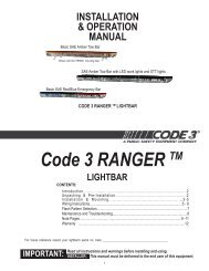
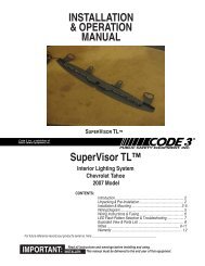
<strong>Installation</strong> and Operation Manual<br />
<strong>Installation</strong> <strong>SuperVisor</strong>-U and Operation Ins<br />
CD3766 Directional<br />
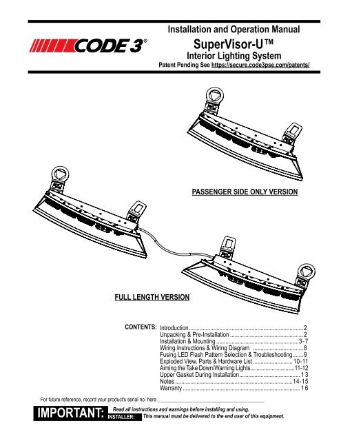
Interior Lighting System<br />
Patent Pending See https://secure.code3pse.com/patents/<br />
PASSENGER SIDE ONLY VERSION<br />
FULL LENGTH VERSION<br />
IMPORTANT:<br />
CONTENTS:<br />
Introduction............................................................................ 2<br />
Unpacking & Pre-<strong>Installation</strong>................................................. 2<br />
<strong>Installation</strong> & Mounting.......................................................3-7<br />
Wiring Instructions & Wiring Diagram ..................................8<br />
Fusing LED Flash Pattern Selection & Troubleshooting........9<br />
Exploded View, Parts & Hardware List........................... 10-11<br />
Aiming the Take Down/Warning Lights.............................11-12<br />
Upper Gasket During <strong>Installation</strong>......................................... 13<br />
Notes..............................................................................14-15<br />
Warranty.............................................................................. 16<br />
For future reference, record your product's serial no. here __________________________________________<br />
Read all instructions and warnings before installing and using.<br />
INSTALLER: This manual must be delivered to the end user of this equipment.
Introduction<br />
The <strong>SuperVisor</strong> U (hereafter calld "unit") is an interior lighting system that fits in the visor area near the top of the windshield. The<br />
Universal <strong>SuperVisor</strong> has room for up to ten Torus Light Heads. Note: The Take Downs and up to (4) of the warning light heads can<br />
be adjusted/aimed in order to put the bright spot as straight forward as possible to achieve the best warning signal (See page 11).<br />
Product Features<br />
Torus light head options: Flashing = Red, Blue, Amber, and White--------Independent Flashing<br />
Take Down Lights = White<br />
Size Full Unit: 50.75" MAX to 43.56"MIN length X 2.12" tall X 6.87" deep--------------------------------------------------Weight: 7.5 lbs<br />
Size Pass Only Unit: 21.75" length X 2.12" tall X 6.87" deep-------------------------------------------------------------------Weight: 4.0 lbs<br />
warning!<br />
The use of this or any warning device does not ensure that all drivers can or will observe or react to an<br />
emergency warning signal. Never take the right-of-way for granted. It is your responsibility to be sure you can<br />
proceed safely before entering an intersection, driving against traffic, responding at a high rate of speed, or<br />
walking on or around traffic lanes. The effectiveness of this warning device is highly dependent upon correct<br />
mounting and wiring. Read and follow the manufacturer’s instructions before installing or using this device. The<br />
vehicle operator should insure daily that all features of the device operate correctly. In use, the vehicle operator<br />
should insure the projection of the warning signal is not blocked by vehicle components (i.e.: open trunks or<br />
compartment doors), people, vehicles, or other obstructions. This equipment is intended for use by authorized<br />
personnel only. It is the user’s responsibility to understand and obey all laws regarding emergency warning<br />
devices. The user should check all applicable city, state and federal laws and regulations. <strong>Code</strong> 3, Inc., assumes<br />
no liability for any loss resulting from the use of this warning device. Proper installation is vital to the performance<br />
of this warning device and the safe operation of the emergency vehicle. It is important to recognize that the<br />
operator of the emergency vehicle is under psychological and physiological stress caused by the emergency<br />
situation. The warning device should be installed in such a manner as to: A) Not reduce the output performance<br />
of the system, B) Place the controls within convenient reach of the operator so that he can operate the system<br />
without losing eye contact with the roadway. Emergency warning devices often require high electrical voltages<br />
and/or currents. Properly protect and use caution around live electrical connections. Grounding or shorting of<br />
electrical connections can cause high current arcing, which can cause personal injury and/or severe vehicle<br />
damage, including fire. Any electronic device may create or be affected by electromagnetic interference. After<br />
installation of any electronic device operate all equipment simultaneously to insure that operation is free of<br />
interference. Never power emergency warning equipment from the same circuit or share the same grounding<br />
circuit with radio communication equipment. All devices should be mounted in accordance with the manufacturer's<br />
instructions and securely fastened to vehicle elements of sufficient strength to withstand the forces applied to the<br />
device. Driver and/or passenger air bags (SRS) will affect the way equipment should be mounted. This device<br />
should be mounted by permanent installation and within the zones specified by the vehicle manufacturer, if any.<br />
Any device mounted in the deployment area of an air bag will damage or reduce the effectiveness of the air<br />
bag and may damage or dislodge the device. Installer must be sure that this device, its mounting hardware and<br />
electrical supply wiring does not interfere with the air bag or the SRS wiring or sensors. Mounting the unit inside<br />
the vehicle by a method other than permanent installation is not recommended as unit may become dislodged<br />
during swerving, sudden braking or collision. Failure to follow instructions can result in personal injury. PROPER<br />
INSTALLATION COMBINED WITH OPERATOR TRAINING IN THE PROPER USE OF EMERGENCY WARNING<br />
DEVICES IS ESSENTIAL TO INSURE THE SAFETY OF EMERGENCY PERSONNEL AND THE PUBLIC.<br />
Unpacking & Pre-installation<br />
Carefully remove the Unit and place it on a flat surface, taking care not to scratch the lenses or damage the cable coming out of the<br />
Housing. Examine the unit for transit damage, broken optics, LED's, etc. Report any damage to the carrier and keep the shipping carton.<br />
Standard light bars are built to operate on 12 volt D.C. negative ground (earth) vehicles. If you have an electrical system other than 12<br />
volt D.C. negative ground (earth), and have not ordered a specially wired light bar, contact the factory for instructions.<br />
Test the unit before installation. To test, touch the black wire to the ground (earth) and the other wires to +12 volts D.C., in accordance<br />
with the instructions attached to the cable (an automotive battery is preferable for this test). A battery charger may be used, but note that<br />
some electronic options may not operate normally when powered by a battery charger. If problems occur at this point, contact the factory<br />
Note: Before beginning the installation process, be absolutely certain<br />
that the Light Bar functions as desired (See pages 8 & 9 for options)!<br />
warning!<br />
Utilizing non-factory supplied screws and/or mounting brackets and/or the improper<br />
number of screws may result in loss of warranty coverage on the equipment.<br />
Mounting Hardware - All mounting hardware is packed in a small bag inside the main carton. See pages 10 & 11 for part descriptions<br />
and quantities.<br />
2
<strong>Installation</strong> & Mounting Instructions-Full <strong>SuperVisor</strong> U or Passenger Side Only <strong>SuperVisor</strong> U<br />
Note to the installer: The following steps for the installation of the Unit may seem redundant or unnecessary, but in<br />
order for the product to fit and perform properly these steps are necessary. The Unit's Inner and Outer Mounting Brackets<br />
may require some trimming to properly fit the irregular recessed shapes of the the vehicle's headliner fabric, the shapes<br />
of the plastic sun visor pivot brackets, and the shapes of the sun visor clip brackets. Many times the plastic brackets are<br />
recessed up into the fabric of the headliner. These recesses will require that the outer edges of the Unit's Outer Mounting<br />
Brackets be trimmed to fit into the recess. The fit of the Unit's Inner and Outer Mounting Brackets to the headliner can<br />
greatly affect the angles the brackets will be at when installed due to the inconsistant crush of the vehicle's headliner fabric<br />
and the irregular shapes of the vehicle's sheet metal above the headliner fabric.The Unit's Inner and Outer Mounting Brackets<br />
may require bending to align with the Unit's Slotted Mounting Brackets and Outer Panels in the final assembly. The most<br />
important issue in the installation is that the Unit must be securely fastened to the vehicle for passeneger safety and the unit<br />
must be level in the vehicle to insure that the light bar will perform as intended (See Figure 3 on page 6). The installation<br />
process may require trial and error to make adjustments to the Unit's Brackets to fit properly in their final location.<br />
Note: If you have problems with the Upper Gasket comming loose or being in the way, see page 13 for a simple<br />
system to hold the gasket out of the way until the final installation.<br />
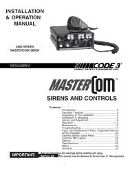
Step 1 Remove the vehicle's plastic outer visor pivot brackets to determine which of the (4) Unit's Outer Mounting Bracket<br />
sets best fit the vehicle (See Figure-1 on page 5 for the available options). The Standard Round Outer Mounting Bracket<br />
with the Triangular Washer will be the most commonly used set as the Triangular Washer allows the Round Outer Mounting<br />
Bracket to rotate to accomodate extreme angles of rotation for adjustment while allowing the triangular hole in the washer to<br />
align with the most common visor pivot bracket. If none of the Universal <strong>SuperVisor</strong>'s Outer Mounting Bracket versions appear<br />
to work for your application the Universal <strong>SuperVisor</strong>'s Rectangular Outer Mounting Brackets may be cut off as shown<br />
in Figure 5 on page 7. The brackets may then be used as a template to drill (2) 9/64" .140" diameter mounting holes directly<br />
through the fabric of the headliner and through the vehicle's sheet metal above the headliner so that the brackets can<br />
be mounted directly to the vehicle's headliner using the supplied #8 X 1" Black Phillips Truss Head Sheet Metal Screws.<br />
Caution: Before doing any drilling in the vehicle, refer to the vehicle's service manual to pull the fabric headliner<br />
down slightly and observe the locations of any wiring or sensing devices to avoid doing damage to them!!! Also be<br />
very careful not to drill through the vehicle's roof. If none of the bracket options are appropriate to the vehicle you are<br />
installing the Unit in, it may be necessary to make your own mounting brackets.<br />
Step 2 Remove the vehicle's plastic inner visor clips. In a majority of vehicles the plastic inner visor clips will fit in the rectangular<br />
hole in the Unit's Inner Mounting Brackets but the Inner Mounting Brackets may require some modification with a<br />
file or other cutting tool to clear the shapes in the vehicle's plastic visor clips. For vehicles with smaller inner visor clips you<br />
may need to use the Unit's supplied Rectangular Washer in your vehicle application. Make any necessary modifications to<br />
the Inner Mounting Brackets to make the vehicle's plastic visor brackets fit in the hole. If the Inner Mounting Brackets do not<br />
work, the Inner Mounting Brackets may also be cut off as shown in Figure 5 on page 7 and the brackets can be mounted<br />
by using the brackets as a template to drill (2) 9/64" .140" diameter mounting holes directly in the vehicle's headliner and<br />
the sheet metal above the headliner fabric so that the brackets can be mounted directly to the vehicle's headliner using<br />
the supplied #8 X 1" Black Phillips Truss Head Sheet Metal Screws. Caution Again: Before doing any drilling in the<br />
vehicle, pull the headliner down slightly and observe the locations of any wiring or sensing devices to avoid doing<br />
damage to them!!! Again as with the Outer Mounting Brackets, be very careful not to drill through the vehicle's<br />
roof. If none of the bracket options are appropriate to the vehicle you are installing the Unit in, it may be necessary to make<br />
your own mounting brackets for your application.<br />
Step 3 Loosely fasten each of the Unit's Outer and Inner Mounting Brackets to a Slotted Mounting Bracket with (2) of<br />
each of the provided 1/4"-20 X 1/2" long Carriage Bolts, 1/4" Internal Tooth Lock Washers, and the 1/4"-20 Acorn Nuts as<br />
shown in Figure-2 on page 5. The Carriage bolts can be located in the slots in the brackets in what ever combination of<br />
locations works best for your application to position the brackets at the required angles. Note: Figure-2 only shows the<br />
assembly of the Unit's Inner Mounting Brackets but the assembly of the Outer Mounting Brackets is the same. As<br />
stated above and as shown in Figure-2, it is recommended that each Outer or Inner Mounting Bracket is attached<br />
to a Slotted Mounting Bracket with (2) of each of the 1/4"-20 X 1/2" long Carriage Bolts, 1/4" Internal Tooth Lock<br />
Washers, and the 1/4"-20 Acorn Nuts. While the design allows for a good deal of adjustment in some circumstances<br />
where the brackets need to be attached at an extreme angle to each other, it may be necessary to file out the<br />
mounting slots slightly in the brackets to accomodate the second fastener.<br />
3
<strong>Installation</strong> and Mounting Instructions: Cont.<br />
Step 4 Have an assistant hold either the Passenger or the Driver side of the the Unit up to the vehicle's windshield as<br />
close as possible to desired location. Make sure that the rubber gasket on the Unit's lower Panel folds down to conform<br />
to the vehicle's windshield curve and that the gasket at the top of the Unit folds back towards the passenger compartment<br />
to conform to the angle of the vehicle's windshield (See Figure 3 on page 6). Note: In operation, the purpose of these<br />
gaskets is to block out as much flash back light from the driver's view as possible so that the driver will not be<br />
distracted. While the Unit is held in position, hold up the Inner and Outer Mounting Bracket assemblies to the Outer<br />
Panel of the Unit to determine the appropriate mounting hole locations that best line up with the slots in the Slotted Mounting<br />
Brackets for each of the bracket assemblies.<br />
Step 5 Loosley thread the 1/4" Internal Tooth Lock Washers, and the 1/4"-20 X 3/8" long Phillips Pan Head Screws into<br />
the the closest appropriate mounting hole locations for the hardware and make adjustments to position them close to their<br />
final position. See the under side view of the Unit Assembly in Figure 4 on page 6 for bracket assembly orientation and<br />
mounting hole adjustment choices. As stated in note 2 above and as shown in Figure-4 it is recommended that each of<br />
the Unit's Slotted Mounting Bracket use (2) each of the 1/4" Internal Tooth Lock Washers, and 1/4"-20 X 3/8" long Phillips<br />
Pan Head Screws to mount it to the Unit's Outer Panel. Line up the holes in the Unit's Inner and Outer Mounting Brackets<br />
with the holes in the vehicle's headliner where the vehicle's visor pivot brackets and the visor clips were installed. Once<br />
the brackets are aligned, tighten the screws in the Unit's Outer Panel only tight enough too keep the Slotted Brackets in<br />
their orientation and keep them from moving so that they will stay in position.<br />
Step 6 Observe the angles and positions of the Inner and Outer Mounting Brackets and then disassemble and remove<br />
them from the slotted mounting brackets.<br />
Step 7 Hold the Unit's Outer Mounting Bracket for the side of the vehicle you have been working on up in position with<br />
the hole in the vehicle's headliner where the plastic outer visor pivot bracket was and determine what modifications if necessary<br />
will be required to make it fit up against the headliner at the approximate angle it was in when you observed it in<br />
step 6 above. Make any required modifications to make the bracket fit up against the headliner and fit the vehicle's plastic<br />
outer pivot bracket.<br />
Step 8 Mount the Unit's Outer Mounting Bracket and the vehicle's plastic visor pivot bracket using the vehicle's OEM<br />
fasteners making sure the bracket is oriented at approximately the same angle it was at when you observed it in step 6<br />
above. If the vehicle's OEM fasteners are too short either use the #8 X 1" Black Phillips Truss Head Sheet Metal Screws<br />
or if the supplied fasteners will not work obtain appropriate screws at your local hardware store. Tighten the screws up to<br />
snug the Outer Mounting Bracket tight up against the vehicle's headliner and in position.<br />
Step 9 Mount the Unit's Inner Mounting Bracket and the vehicle's inner visor clip using the vehicle's OEM fastener<br />
making sure the bracket is oriented at approximately the same angle it was at when you observed it in step 6 above. If the<br />
vehicle's OEM fastener is too short either use the #8 X 1" Black Phillips Truss Head Sheet Metal Screw or if the supplied<br />
fasteners will not work obtain appropriate screws at your local hardware store. Tighten the screw up to snug the Inner<br />
Mounting Bracket tight up against the vehicle's headliner and in position.<br />
Step 10 Hold the Unit Back up to the Installed Unit's Outer and Inner Mounting Brackets and determine if the angles of<br />
the brackets need to be bent to re align them with the angled mounting tabs of the Slotted Mounting Brackets to facilitate<br />
the final installation of the Unit. If necessary remove the Outer and Inner Mounting Brackets and bend the angles to line<br />
them up with the Slotted Mounting Brackets or remove and bend the angles of the Slotted Mounting Brackets so that they<br />
line up. Reposition all of the the Brackets, remount them to the vehicle's headliner and re fasten the Slotted Mounting<br />
Brackets to the Inner and Outer Mounting Brackets. Make any required final adjustments and fully tighten all hardware.<br />
Note 1: The Unit's Gaskets must be up against the vehicle's windshield to block out as much light as possible.<br />
If you are experiencing problems keeping the upper gasket in place see page 13 for a tip on how to hold the gaskets<br />
in place while completing the installattion.<br />
Note 2: the Unit must be as close to level to the ground as possible in the front to back direction when it is in it's<br />
final location. The Unit may be slightly out of level in the left to right direction but should still be somewhat close<br />
to level in order to obtain maximum performance from the product when installed (See Figure 3 on page 6). It is<br />
very important that the vehicle is setting on a level floor when checking the Unit for level before making adjustments<br />
for the final assembly.<br />
4
<strong>Installation</strong> and Mounting Instructions: Cont.<br />
Step 11 Repeat steps 4 through 10 for the opposite side of the Unit.<br />
Step 12 Once both sides of the Unit are installed, leveled and in the final position, loosen the screws on each<br />
of the Inner and Outer Light Blocker Brackets, swing them up against the windshield and retighten the screws to<br />
block out any flash back light that might come out the sides of the Unit (see Figure 6 on page 7).<br />
Step 13 Route the Unit's cable as desired and complete the wiring process.<br />
After the Unit is installed and wired, the Take Down Light Heads and up to (4) of the Warning Light Heads<br />
can be aimed if so equipped, See Page 11.<br />
STANDARD ROUND OUTER<br />
MOUNTING BRACKET<br />
OVAL OUTER<br />
MOUNTING BRACKET<br />
RECTANGULAR OUTER<br />
MOUNTING BRACKET<br />
SUV (TAHOE) OUTER<br />
MOUNTING BRACKET<br />
INNER MOUNTING BRACKET<br />
SLOTTED MOUNTING BRACKET<br />
STANDARD ROUND OUTER<br />
MOUNTING BRACKET<br />
W TRIANGULAR WASHER<br />
STANDARD INNER<br />
MOUNTING BRACKET<br />
W RECTANGULAR WASHER<br />
2015 FORD F150 OUTER<br />
MOUNTING BRACKET<br />
2015 FORD F150 INNER<br />
MOUNTING BRACKET<br />
2015 DODGE RAM OUTER<br />
MOUNTING BRACKET<br />
2015 DODGE RAM INNER<br />
MOUNTING BRACKET<br />
Figure 1<br />
Figure 2<br />
5
<strong>Installation</strong> and Mounting Instructions: Cont.<br />
THIS GASKET FLANGE TO FOLD<br />
BACK THIS DIRECTION TOWARD<br />
PASSENGER COMPARTMENT<br />
WINDSHIELD<br />
INTERIOR<br />
SURFACE<br />
THIS GASKET FLANGE TO FOLD<br />
DOWN THIS DIRECTION WITH<br />
CONTOUR OF WINDSHIELD<br />
IN IT'S FINAL POSITION, THE SUPERVISOR MUST BE<br />
AS LEVEL AS POSSIBLE IN FRONT TO BACK AXIS<br />
IN IT'S FINAL POSITION, THE SUPERVISOR SHOULD BE<br />
AS LEVEL AS POSSIBLE IN LEFT TO RIGHT AXIS BUT IS<br />
NOT AS CRITICAL AS FRONT TO BACK AXIS<br />
Figure 3<br />
MOUNTING HOLE<br />
LOCATION CHOICES<br />
MOUNTING HOLE<br />
LOCATION CHOICES<br />
INNER MOUNTING<br />
BRACKET ASSEMBLYS<br />
OUTER MOUNTING<br />
BRACKET ASSEMBLYS<br />
UNDER SIDE VIEW OF UNIVERSAL SUPERVISOR<br />
Figure 4<br />
6
<strong>Installation</strong> and Mounting Instructions: Cont.<br />
USE HOLES AS A TEMPLATE TO<br />
DRILL MOUNTING HOLES IN<br />
VEHICLE AT DESIRED LOCATION<br />
CUT OFF AS SHOWN FOR<br />
DRILLED AND FASTENED<br />
BRACKETS<br />
RECOMMEND 1/8" RADIUS 2X<br />
RECOMMEND 1/8" RADIUS 2X<br />
OUTER MOUNTING BRACKET<br />
RECTANGULAR<br />
Figure 5<br />
INNER MOUNTING BRACKET<br />
TO ADJUST LIGHT BLOCKER BRACKETS LOOSEN<br />
THE FASTENING SCREW SLIGHTLY<br />
TO ADJUST LIGHT BLOCKER BRACKETS, SWING<br />
UP AS SHOWN UNTIL THE BRACKET TOUCHES<br />
THE WINDSHIELD AND RETIGHTEN THE<br />
FASTENING SCREW<br />
Figure 6<br />
Caution: Drilling into the housing of the light bar could damage wiring or other internal<br />
components.<br />
7
WARNING:<br />
This unit must be mounted within the interior passenger compartment of the vehicle only. It is not intended for<br />
use in exterior applications. All devices should be mounted in accordance with the manufacturer’s instructions<br />
and securely fastened to vehicle elements of sufficient strength to withstand the forces applied to the device.<br />
Driver and/or passenger air bags (SRS) will affect the way equipment should be mounted. This device should<br />
be mounted by permanent installation and within the zones specified by the vehicle manufacturer, if any. Any<br />
device mounted in the deployment area of an air bag will damage or reduce the effectiveness of the air bag and<br />
may damage or dislodge the device. Installer must be sure that this device, its mounting hardware and electrical<br />
supply wiring does not interfere with the air bag or the SRS wiring or sensors. Mounting the unit inside<br />
the vehicle by a method other than permanent installation is not recommended as unit may become dislodged<br />
during swerving, sudden braking or collision. Failure to follow instructions can result in personal injury.<br />
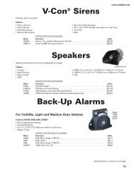
Wiring Instructions<br />
Finish routing the cable as desired. It is advisable to leave an extra loop of cable when installing the light bar to allow for future changes<br />
or reinstallations. Connect the black lead to a solid frame ground (earth), preferably the (-) or ground (earth) side of the battery, and the<br />
power wire to the +12V terminal of the battery. Connect the remaining wires as shown in wiring diagram below.<br />
Warning!<br />
Larger wires and tight connections will provide longer service life for components. For high current wires it<br />
is highly recommended that terminal blocks or soldered connections be used with shrink tubing to protect<br />
the connections. Do not use insulation displacement connectors (e.g. 3M ® Scotchlock type connectors).<br />
Route wiring using grommets and sealant when passing through compartment walls. Minimize the<br />
number of splices to reduce voltage drop. High ambient temperatures (e.g. under hood) will significantly<br />
reduce the current carrying capacity of wires, fuses, and circuit breakers. Use "SXL" type wire in engine<br />
compartment. All wiring should conform to the minimum wire size and other recommendations of the<br />
manufacturer and be protected from moving parts and hot surfaces. Looms, grommets, cable ties, and<br />
similar installation hardware should be used to anchor and protect all wiring. Fuses or circuit breakers<br />
should be located as close to the power takeoff points as possible and properly sized to protect the wiring<br />
and devices. Particular attention should be paid to the location and method of making electrical connections<br />
and splices to protect these points from corrosion and loss of conductivity. Ground terminations should<br />
only be made to substantial chassis components, preferably directly to the vehicle battery. The user should<br />
install a fuse sized to approximately 125% of the maximum Amp capacity in the supply line to protect<br />
against short circuits. For example, a 30 Amp fuse should carry a maximum of 24 Amps. DO NOT USE<br />
1/4" DIAMETER GLASS FUSES AS THEY ARE NOT SUITABLE FOR CONTINUOUS DUTY IN SIZES<br />
ABOVE 15 AMPS. Circuit breakers are very sensitive to high temperatures and will "false trip" when<br />
mounted in hot environments or operated close to their capacity.<br />
RED<br />
THIS WIRE IS ALSO<br />
FOR TAKE DOWNS<br />
WHEN SO EQUIPPED<br />
RED/WHITE<br />
THIS WIRE IS ALSO<br />
FOR TAKE DOWNS<br />
WHEN SO EQUIPPED<br />
LT BLUE<br />
PURPLE<br />
WHITE<br />
ORANGE<br />
GREEN/WHT<br />
PINK<br />
BROWN<br />
BROWN/WHT<br />
PASSENGER<br />
SIDE<br />
BLACK-------------NEGATIVE GROUND<br />
FUSE SIZE CALCULATION:<br />
USE .5 AMP FOR EACH LED HEAD<br />
WIRING DIAGRAM<br />
DRIVER<br />
SIDE<br />
8
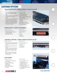
LED Fusing Considerations<br />
Although the average current draw per module is very low, due to the type of circuit used to power each module, the instantaneous<br />
peak current to a module can be significantly higher during low voltage conditions. To avoid prematurely blowing ATO style<br />
fuses or tripping breakers it is recommended the following rule-of-thumb be used to size fuses or breakers. This is especially<br />
important in lightbars with many LED modules running off a single fused source.<br />
Minimum fuse size calculation: (See Wiring Diagram page 5)<br />
For LED 12 volt electrical current only<br />
.5 X (number of 3 LED modules being fused) = Total Electrical Current at 12.8 VDC<br />
Warning!<br />
This Product contains high intensity LED devices. To prevent eye damage,<br />
DO NOT stare into light beam at close range.<br />
Changing Flash Patterns<br />
To change the flash patterns on the LED Light Heads, remove the mounting screws that attach the <strong>SuperVisor</strong>'s Cover to the<br />
Outer Panel to gain access to the printed circuit boards inside (see the exploded view on page 10). Momentarily short and<br />
release the pattern change prongs as shown below to change patterns. Carefully replace the <strong>SuperVisor</strong>'s Cover over the<br />
Outer Panel and replace the Cover Mounting Screws.<br />
Note: Be extremely careful to replace the wiring such that you don't pinch a wire when you replace the<br />
<strong>SuperVisor</strong>'s Cover. Test the unit to be sure that it works properly.<br />
Directional Module Flash Pattern - Table 2<br />
Cycle Flash-70 - (DEFAULT)<br />
Variable Flash Single<br />
NFPA Quad Flash-80<br />
Cycle Flash-150<br />
1. Momentarily short and release to<br />
Quad Flash-70<br />
Five Flash-150<br />
change patterns<br />
Steady Burn<br />
Quad Flash-150<br />
2. Hold for 5 seconds to reset the<br />
Five Flash-70<br />
Triple Flash-150<br />
flash pattern to the first pattern<br />
Triple Flash-70<br />
Double Flash-150<br />
Double Flash-70<br />
Single Flash-150<br />
JP1 Single Flash-70<br />
Single Flash-250<br />
Quad Pop Flash-70<br />
Single Flash-375<br />
Triple Pop Flash-70<br />
Torus 3LED PCB<br />
Flash Pattern Header for Torus<br />
Troubleshooting<br />
All <strong>SuperVisor</strong>TLs are thoroughly tested prior to shipment. However, should you encounter a problem during installation or during the<br />
life of the product, follow the guide below for information on repair and troubleshooting. Additional information may be obtained from<br />
the factory technical help line at 314-996-2800. Follow the guide below for information on repair and troubleshooting.<br />
TROUBLESHOOTING GUIDE<br />
Note: LED modules must be replaced as a module. There are no user serviceable parts.<br />
PROBLEM<br />
QUESTIONS<br />
POSSIBLE CAUSE<br />
SOLUTION<br />
LED module not<br />
operating when<br />
powered.<br />
N/A<br />
a. Bad power/ground<br />
connection.<br />
b. Defective module.<br />
a. Fix connection.<br />
b. Replace module<br />
9
26<br />
Parts List<br />
24<br />
16<br />
27<br />
13<br />
25<br />
12<br />
11<br />
14<br />
15<br />
10<br />
7<br />
9<br />
8<br />
6<br />
5<br />
4 2 1<br />
3<br />
22<br />
23<br />
Reference Number Part Description Part Number Quantity<br />
1 Outer Panel - Driver Side T15510 1<br />
2 Outer Panel -Passenger Side T15512 1<br />
3 Mounting Brkt-Slotted T15531 4<br />
4 Outer Light Blocker T15517 2<br />
5 Inner Light Blocker T15516 2<br />
6 Torus Light Head Module Contact <strong>Code</strong> 3, Inc for P/N 10<br />
7 Chassis-Passenger Side T15513 1<br />
8 Chassis-Driver Side T15511 1<br />
9 Mtg Plate-Chassis Gasket T15514 2<br />
10 Triangular Washer-Outer Mounting Bracket T15519 2<br />
11 Outer Mounting Bracket-Round T15533 2<br />
10
Hardware/Parts-Cont. Items 17 Thru 21 Not Shown in Exploded View<br />
Reference Number Part Description Part Number Quantity<br />
12 Outer Mounting Bracket-Oval T15536 2<br />
13 Outer Mounting Bracket-Rectangular T15537 2<br />
14 Inner Mounting Brackets T15526 2<br />
15 Rectangular Washer-Inner Mounting Bracket T15548 2<br />
16 Outer Mounting Bracket-Tahoe T15547 2<br />
17 1/4"-20 X 1/2" Long Carriage Bolt Black Zinc T15541 8<br />
18 1/4"-20 Acorn Nut Black Zinc T15540 8<br />
19 1/4"-20 X 3/8" Long Phillips Pan Head Screw Black Zinc T89965 8<br />
20 1/4"Internal Tooth Lock Washer T06935 16<br />
21 #8 X 1" Long Phillips Truss Head Sheet Metal Screw Black Oxide T15280 10<br />
22 .625 Dia Plug Cap T04797 7<br />
23 .500 Dia Plug Cap T00337 12<br />
24 Outer Mounting Bracket-2015 Ford F150 T17198 2<br />
25 Inner Mounting Bracket-2015 Ford F150 T17199 2<br />
26 Outer Mounting Bracket-2015 Dodge Ram T17182 2<br />
27 Inner Mounting Bracket-2015 Dodge Ram T17181 2<br />
Note: Some of the above listed parts may not be available for purchase!<br />
Adjusting/Aiming the Take Down/Warning Lights<br />
1. Using a pocket knife or other thin tool, remove the (3) Take Down Light Adjustment Access Hole Caps as<br />
shown in Figure-7 on page 12 (Driver Side Shown---On a new install this step may not be necessary).<br />
2. Energize the Take Down/warning Light to enable the aiming process.<br />
3. With a phillips screwdriver (Note some versions may require a #20 Torx Driver or a 1/4" Hex Driver) loosen the<br />
(2) Take Down Light Head Fasteners to just loosen them up, no more that 1/4 turn as shown in Figure-8 on page<br />
12. The outer panel is shown clear to show the internal fasteners and the Take Down Light/Warning Light Head<br />
Mounting Bracket.<br />
4. With a 1/4" flat blade screwdriver turn the Take Down Light Head to aim it in the desired direction as shown in<br />
Figure-9 on page 12.<br />
11
Adjusting/Aiming the Take Down/Warning Lights-Cont.<br />
5. When the Take Down Light Head is aimed in the desired direction retighten the fasteners with the phillips<br />
screwdriver taking care not to allow the light head to move. Note: It is advisable to hold the Take Down Light<br />
Head in position with the flat blade screwdriver to prevent movement of the light head while tightening the<br />
fasteners. It works best if you use a phillips screwdriver that is longer than the flat blade screwdriver as shown<br />
in Figure-10 on page 12.<br />
6. Replace the Take Down Adjustment Access Hole Caps and repeat Steps 1 through 6 if desired on the opposite<br />
side of the vehicle. Note: If extreme adjustments have been made it may be necessary to trim the cap to<br />
get it to fit back in the hole.<br />
Figure 7<br />
Figure 8<br />
Figure 9<br />
Figure 10<br />
12
For Problems with the Upper Gasket during installation!<br />
If you experience problems with the Upper Gasket during installation, follow the simple steps below.<br />
1. Take (5) short pieces of masking tape and stick about 1/4 of an inch of the end of each piece of the<br />
tape to the gasket as shown in Figure-11 below.<br />
2. Pull the gasket back with the tape and stick the other end of the masking tape to the Unit's housing in<br />
a location that won't interfere with the installation. Make sure you leave a little tail of the masking tape<br />
loose so you can pull it loose easily later.<br />
3. When you have the unit mounted and in the desired position/location with all of the fasteners tightened<br />
just pull the tails of the tape loose from the unit's housing and then just pull it loose from the<br />
gasket. The gasket will gradually flip up against the windshield and into it's final position.<br />
Figure 11<br />
13
NOTES:<br />
14
NOTES:<br />
15
WARRANTY<br />
<strong>Code</strong> 3, Inc.'s emergency devices are tested and found to be operational at the time of manufacture. Provided<br />
they are installed and operated in accordance with manufacturer's recommendations, <strong>Code</strong> 3, Inc. guarantees all<br />
parts and components except the lamps to a period of 1 year, LED Lighthead modules to a period of 5 years (unless<br />
otherwise expressed) from the date of purchase or delivery, whichever is later. Units demonstrated to be defective<br />
within the warranty period will be repaired or replaced at the factory service center at no cost.<br />
Use of lamp or other electrical load of a wattage higher than installed or recommended by the factory, or use<br />
of inappropriate or inadequate wiring or circuit protection causes this warranty to become void. Failure or destruction<br />
of the product resulting from abuse or unusual use and/or accidents is not covered by this warranty. <strong>Code</strong> 3, Inc.<br />
shall in no way be liable for other damages including consequential, indirect or special damages whether loss is due<br />
to negligence or breach of warranty.<br />
CODE 3, inc. makes no other express or implied warranty including, without limitation,<br />
warranties of fitness or merchantability, with respect to this product.<br />
PRODUCT RETURNS<br />
If a product must be returned for repair or replacement*, please contact our factory to obtain a Return<br />
Goods Authorization Number (RGA number) before you ship the product to <strong>Code</strong> 3, Inc. Write the RGA number<br />
clearly on the package near the mailing label. Be sure you use sufficient packing materials to avoid damage to<br />
the product being returned while in transit.<br />
*<strong>Code</strong> 3, Inc. reserves the right to repair or replace at its discretion. <strong>Code</strong> 3, Inc. assumes no responsibility or liability for expenses incurred for the removal and /or<br />
reinstallation of products requiring service and/or repair.; nor for the packaging, handling, and shipping: nor for the handling of products returned to sender after the service has been<br />
rendered.<br />
NEED HELP? Call our Technical Assistance HOTLINE ‐ (314) 996-2800<br />
10986 North Warson Road<br />
St. Louis, MO 63114<br />
Customer Service<br />
(314) 426-2700<br />
cs-c3@code3esg.com<br />
www.code3esg.com<br />
A Division of ESG | www.eccogroup.com<br />
Revision 2, 02/15 - Instruction Book Part No. T15538<br />
16