LIT3 Mounting Kit Installation Guide - Code 3 Public Safety Equipment
LIT3 Mounting Kit Installation Guide - Code 3 Public Safety Equipment
LIT3 Mounting Kit Installation Guide - Code 3 Public Safety Equipment

You also want an ePaper? Increase the reach of your titles
YUMPU automatically turns print PDFs into web optimized ePapers that Google loves.
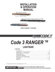
INSTALLATION<br />
&<br />
OPERATION<br />
MANUAL<br />
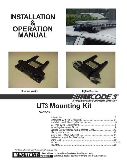
Standard Version<br />
Lighted Version<br />
IMPORTANT:<br />
<strong>LIT3</strong> <strong>Mounting</strong> <strong>Kit</strong><br />
CONTENTS:<br />
Introduction.....................................................................................2<br />
Unpacking and Pre-<strong>Installation</strong>.........................................................2<br />
<strong>Installation</strong> and <strong>Mounting</strong>-Standard Mount.........................................2-8<br />
55 Watt Lamp Replacement.............................................................8<br />
<strong>Mounting</strong>-Permanent Mount..............................................................9<br />
Retrofit Lighted <strong>Mounting</strong> <strong>Kit</strong> to existing Lightbar...............................10<br />
Wiring Instructions..........................................................................10<br />
LED Flash Pattern Selection ...........................................................11<br />
Maintenance and Troubleshooting....................................................11<br />
Parts List.......................................................................................12<br />
Notes.............................................................................................13-15<br />
Warranty........................................................................................16<br />
For future reference, record your product's serial no. here __________________________________________<br />
Read all instructions and warnings before installing and using.<br />
INSTALLER: This manual must be delivered to the end user of this equipment.
Introduction<br />
The new <strong>LIT3</strong> <strong>Mounting</strong> <strong>Kit</strong> is a system that provides an attractive and convenient means to attach many of the <strong>Code</strong> 3 Lightbar Products<br />
to Emergency Vehicles.<br />
The Lighted Version can be ordered with 55 watt takedown/alley lights and/or 3 LED optix lightheads in Red, White, Blue or Amber.<br />
!<br />
WARNING!<br />
Unpacking & Pre-installation<br />
Carefully remove the <strong>LIT3</strong> <strong>Mounting</strong> <strong>Kit</strong> from the shipping carton, taking care not to scratch the lenses of the LED Lightheads (if so<br />
equipped). Examine the unit for transit damage, etc. Report any damage to the carrier and keep the shipping carton.<br />
Standard lightbars are built to operate on 12 volt D.C. negative ground (earth) vehicles. If you have an electrical system other than 12<br />
volt D.C. negative ground (earth), and have not ordered a specially wired lightbar, contact the factory for instructions.<br />
If the units you have are the lighted version, test the unit before installation. To test, touch the black wire to the ground (earth) and the red<br />
wire to +12 volts D.C.,<br />
<strong>Installation</strong> & <strong>Mounting</strong><br />
!<br />
WARNING!<br />
The use of this or any warning device does not ensure that all drivers can or will observe or react to an emergency<br />
warning signal. Never take the right-of-way for granted. It is your responsibility to be sure you can proceed<br />
safely before entering an intersection, driving against traffic, responding at a high rate of speed, or walking on or<br />
around traffic lanes.<br />
The effectiveness of this warning device is highly dependent upon correct mounting and wiring. Read and follow<br />
the manufacturer’s instructions before installing or using this device. The vehicle operator should insure daily that<br />
all features of the device operate correctly. In use, the vehicle operator should insure the projection of the<br />
warning signal is not blocked by vehicle components (i.e. open trunks or compartment doors), people, vehicles, or<br />
other obstructions.<br />
This equipment is intended for use by authorized personnel only. It is the user’s responsibility to understand and<br />
obey all laws regarding emergency warning devices. The user should check all applicable city, state and federal<br />
laws and regulations.<br />
<strong>Code</strong> 3, Inc., assumes no liability for any loss resulting from the use of this warning device.<br />
Proper installation is vital to the performance of this warning device and the safe operation of the emergency<br />
vehicle. It is important to recognize that the operator of the emergency vehicle is under psychological and<br />
physiological stress caused by the emergency situation. The warning device should be installed in such a manner<br />
as to: A) Not reduce the output performance of the system, B) Place the controls within convenient reach of the<br />
operator so that he can operate the system without losing eye contact with the roadway.<br />
Emergency warning devices often require high electrical voltages and/or currents. Properly protect and use<br />
caution around live electrical connections. Grounding or shorting of electrical connections can cause high current<br />
arcing, which can cause personal injury and/or severe vehicle damage, including fire.<br />
PROPER INSTALLATION COMBINED WITH OPERATOR TRAINING IN THE PROPER USE OF EMER-<br />
GENCY WARNING DEVICES IS ESSENTIAL TO INSURE THE SAFETY OF EMERGENCY PERSONNEL<br />
AND THE PUBLIC.<br />
Utilizing non-factory supplied screws and/or mounting brackets and/or the improper<br />
number of screws may result in loss of warranty coverage on the equipment.<br />
Do not attempt to attach the mounting feet in any manner<br />
other than described in the following pages. Do not drill<br />
holes through the mounting feet and attach with fasteners<br />
to the vehicle frame. This will void the warranty.<br />
<strong>Mounting</strong> Hardware -<br />
All mounting hardware is packed in a small bag inside the main carton. The main components in the kit are (2) Molded Plastic <strong>Mounting</strong><br />
Feet, (2) Stainless Steel <strong>Mounting</strong> Brackets, (2) Gutter Hooks, and other required hardware. These are all discussed in detail later<br />
2
<strong>Installation</strong> Instructions<br />
Installer Note: If the <strong>LIT3</strong> <strong>Mounting</strong> <strong>Kit</strong> being installed is a Lighted Version, proceed with the following steps! If the<br />
<strong>Mounting</strong> <strong>Kit</strong> being installed is the Standard Version, skip Steps 1 through 8 and start with Step 9 on page 4 of this manual!<br />
<strong>LIT3</strong> <strong>Mounting</strong> <strong>Kit</strong> - Lighted Version<br />
Step 1 Make sure the lightheads on the <strong>Mounting</strong> <strong>Kit</strong> are positioned in the desired location and orientation with respect to the Lightbar<br />
(Example: Takedowns aimed toward the front, Alley Lights aimed toward the sides, and or Lightheads angled as desired, etc.) If the<br />
location or orientation of the lightheads is O.K. skip Steps 2 through 8 and continue on from Step 9.<br />
Step 2 If the location or orientation of the Lightheads must be adjusted, remove the #6 X 1/2" Slide Retention Screw with a #15 Torx Driver<br />
(see Figure 1).<br />
Note: The the 55 Watt Takedown lights are shown in the photos in Figures 1 through 6 below but the steps are the same for<br />
the 3 LED OPTIX Lightheads!<br />
Step 3 Pull out the Lighthead/Slide Shelf (see Figure 2).<br />
Step 4 With the Lighthead/Slide Shelf removed, loosen the #8-32 X 1/4" Long Lighthead <strong>Mounting</strong> Screw with a #2 Phillips screwdriver (see<br />
Figure 3). Note: This is the screw that the Lighthead Pivots on.<br />
Step 5 Loosen the #8-32 X 1/4" Long Lighthead <strong>Mounting</strong> Screw closest to the front of the Lighthead's Lens (see Figure 4). Note: This is<br />
the screw that locks and holds the Lighthead in position.<br />
Step 6 Rotate the light on the slide shelf to the desired position and retighten the two Lighthead <strong>Mounting</strong> Screws. Note: It may be<br />
necessary to remove the front Lighthead <strong>Mounting</strong> Screw shown in Figure 4 to bypass the support rib and then replace it<br />
when the desired position is achieved.<br />
Step 7 Tuck the wire connecters and the wires back into the Lighthead Cover leaving as little wire out of the cover as possible and making<br />
sure thay are still engaged in the T-Slot in the slide shelf (see Figure 5). Carefully slide the Light Head Slide Shelf back into position while<br />
guiding the wires into the gap provided between the Slide Shelf and the <strong>Mounting</strong> Foot (see Figure 6). Care should be taken to not pinch the<br />
wires at the rear of the slide shelf.<br />
Step 8 Replace the #6 X 1/2" Slide Retention Screw with a #15 Torx Driver again as shown in Figure 1.<br />
FIGURE 1<br />
FIGURE 2 FIGURE 3<br />
FIGURE 4 FIGURE 5 FIGURE 6<br />
3
<strong>Installation</strong> Instructions-Cont.<br />
Note: The following Steps 9 through 13 are the same for both Lighted <strong>Mounting</strong> <strong>Kit</strong>s and Standard <strong>Kit</strong>s (The Lighted Version is<br />
shown)<br />
Note: Before proceeding with Step 9, make sure that the cage nuts are installed on the interior side of the<br />
Stainless Steel <strong>Mounting</strong> Plates as shown in Figure 7 below. If the cage nut is not in the hole, slip one of the<br />
ears of the cage nut into the square hole and use a screwdriver on the opposite side like a shoehorn to install<br />
the cage nut into the hole as shown in Figure 8. If, after the cage nut is installed, the nut seems overly loose or<br />
ready to fall out, use a slender screwdriver to pry the ears of the cage nut outward as shown in Figure 9 to<br />
insure that it is retained during the remainder of the installation.<br />
Step 9 Making sure any wires are out of the way on the Lighted Version of the <strong>Mounting</strong> Foot, position a Stainless Steel <strong>Mounting</strong> Plate through<br />
the slot in the mounting foot (see Figures 10& 11) and into position over the locating bosses on each mounting foot (see Figure 12). Note: The<br />
cage nut must be positioned as shown on the interior side of the mounting plate.<br />
Step 10 Lay the Lightbar upside down on a clean, flat, padded surface (to protect the lenses from being scratched).<br />
Step 11Slide (2) of the 5/16"-18 Carriage bolts on each side of the Lightbar into the slots in the lightbar's frame (see Figure 13).<br />
Step 12 Position a <strong>Mounting</strong> Foot on each side of the Lightbar over the carriage bolts (see Figure 14).<br />
FIGURE 7 FIGURE 8 FIGURE 9<br />
FIGURE 10 FIGURE 11 FIGURE 12<br />
FIGURE 13 FIGURE 14<br />
4
<strong>Installation</strong> Instructions-Cont.<br />
Note: If you are installing a Standard Version of the <strong>Mounting</strong> <strong>Kit</strong>, skip Steps 13 through 16 and proceed with Step 17<br />
"Standard Version" at the bottom of page 6 of this manual.<br />
Step 13 Feed the ends of the power wires from the Lightbar through the holes in the <strong>Mounting</strong> Feet and into the <strong>Mounting</strong> Foot Wire Pockets (see<br />
Figure 15) (See addendum for installation of the through-the-frame wires if your Lightbar is not equipped)<br />
Step 14 Plug the ends of the power wires from the Lightbar into the power wires from the <strong>Mounting</strong> Feet (see Figure 16)<br />
Step 15 Tuck the excess lengths of the power wires into the <strong>Mounting</strong> Foot Wire Pockets (see Figure 17)<br />
Step 16 Position the wire covers into the <strong>Mounting</strong> Foot Wire Pockets (see Figure 18), insert a #8 X 1/4" Sheet Metal Screw into it's mounting hole<br />
(see Figure 19), and tighten the Sheet Metal Screw with a 1/4" hex Driver or a #20 Torx bit (see Figure 20)<br />
FIGURE 15 FIGURE 16 FIGURE 17<br />
FIGURE 18<br />
FIGURE 19 FIGURE 20<br />
Step 17 Lighted Version Slip the Ring Terminal Ends of the Black Ground Wire under the rib on the <strong>Mounting</strong> Feet (see Figure 21), over<br />
the ends of the 5/16"-18 Carriage bolts (see Figure 22) and position a 5/16" split washer and thread a 5/16"-18 Hex Nut onto each of the<br />
Carriage Bolts (see Figure 23). At this point the assembly should look as shown in Figure 24.<br />
FIGURE 21 FIGURE 22 FIGURE 23<br />
FIGURE 24<br />
5
Special Instructions - Lightbar Internal Wiring<br />
<strong>LIT3</strong> mounting kit lightheads may be wired to operate in conjunction with lightheads mounted in the lightbar. Wire jumper T09831 is<br />
provided for a convenient "Y" connection between these lightheads in most <strong>Code</strong>3 lightbars. (See the example shown below)<br />
Step A To connect the takedown lightheads in the <strong>Mounting</strong> <strong>Kit</strong> with those in the Lightbar, locate and unplug the quick slide connector to the<br />
existing takedown lighthead inside the lightbar as shown in Figures 25 and 26 below.<br />
Step B Connect the male quick slide terminal of the T09831 wire jumper supplied in the parts bag to the female quick slide terminal of the lightbar's<br />
takedown power wire disconnected in step A as shown in Figure 27 below.<br />
Step C Connect the female quick slide terminal of the short leg of the T09831 wire jumper to the male quick slide terminal of the lightbar's takedown<br />
lighthead disconnected in step A as shown in Figure 28 below.<br />
Step D Connect the female quick slide terminal of the long leg of the T09831 wire jumper to the male quick slide terminal of the wire passing through<br />
the lightbar frame and connected to the takedown light in the <strong>LIT3</strong> <strong>Mounting</strong> <strong>Kit</strong> as shown in Figure 29. When the wires are connected correctly they<br />
will look as shown in Figure 30.<br />
Step E Repeat these steps for all (4) Lightheads of the <strong>Mounting</strong> <strong>Kit</strong>, then bundle the wires and wire tie them to the other wires inside<br />
the lightbar as shown in Figure 31.<br />
FIGURE 25 FIGURE 26 FIGURE 27<br />
FIGURE 28 FIGURE 29 FIGURE 30<br />
FIGURE 31<br />
<strong>Installation</strong> Instructions-Cont.<br />
Step 17 Standard Version Position a 5/16" split washer and thread the 5/16"-18 Hex Nut onto the Carriage Bolts (see Figure 32)<br />
FIGURE 32<br />
6
<strong>Installation</strong> Instructions-Cont.<br />
Step 18 To position the mounting feet on the Light bar Frame, measure the distance specified below from the outer edge of the Light bar Lens to the<br />
face of the <strong>Mounting</strong> Foot and tighten the 5/16"-18 Hex Nut with a 1/2" socket wrench making sure the legs of the <strong>Mounting</strong> Feet are parallel to the<br />
Lightbar Frame.<br />
For the Ford Crown Victoria-Measure 1" from the outer edge of the Lightbar Lens to the outer <strong>Mounting</strong> Foot Face (see Figure 33)<br />
For the 2005 Chevy Impala-Make the the outer edge of the Lightbar Lens flush to the outer face of the <strong>Mounting</strong> Foot (see Figure 34)<br />
Note: The above measurements were based on a 47 inch Lightbar and 2005/2006 model year vehicles, for future or other vehicle models<br />
or Customer personal preferance, the measurements may need to be adjusted as needed.<br />
FIGURE 33 FORD CROWN VICTORIA<br />
FIGURE 34 CHEVROLET IMPALA<br />
Step 19 Attach the Wedge Shaped Rubber <strong>Mounting</strong> Foot Pad by pushing the christmas tree shaped rib feature into the space between the<br />
two center ribs on the <strong>Mounting</strong> Feet as shown in Figure 35. Make sure the thickest side of the pad is toward the outside also as shown in<br />
Figure 35. The pads when installed to the <strong>Mounting</strong> feet properly will look as shown in Figure 36. If installed in the reversed position, the<br />
pads may easily fall out if jostled. Note: The Permanent mount version of the Rubber <strong>Mounting</strong> Foot Pad has a differant shape to<br />
work on flat surfaces (see Figure 37).<br />
Note: There are (4) <strong>Mounting</strong> Foot Pad Spacers included in the hardware package for additional padding or adjustment of the<br />
<strong>Mounting</strong> <strong>Kit</strong> to improve the fit to the vehicle's roof contour. The <strong>Mounting</strong> Foot Pad Spacers have adhesive to allow them to<br />
be attached to the <strong>Mounting</strong> Foot Pads. If adjustment is required peel away the protective paper to expose the adhesive and<br />
attach it to the flat side of the Rubber <strong>Mounting</strong> Foot Pad Wedges. It is best to place the Lightbar in position on the vehicle<br />
to determine if <strong>Mounting</strong> Foot Pad Spacers are required to obtain a level fit or to prevent the bar from touching the roof at the<br />
center.<br />
FIGURE 35 FIGURE 36 FIGURE 37<br />
Note: For <strong>Installation</strong> instructions of permanent mount version skip to Step 1 on page 9 of this Manual!<br />
Step 20 Standard Mount Position one of the Gutter Hooks on the vehicle with the large mounting hole centered in the gap between the front and rear<br />
doors of the vehicle and use it as a template to mark the mounting holes for drilling. If necessary, pull the vehicle's weatherstripping out of the way or in<br />
some cases it may require trimming the weatherstripping.<br />
Step 21 Drill the <strong>Mounting</strong> holes with a 3/32" drill. Note: Make sure the holes are drilled deep enough for the screws as on some vehicles there<br />
are two layers of sheet metal to drill through in the gutter area!<br />
Step 22 Apply soft pads between the Gutter Hook and the vehicle's roof if needed to protect the Vehicle's finish. Apply user supplied RTV Sealant to<br />
each of the holes and to the heads of the sheet metal screws to prevent rust and seal against leaks. Install the sheet metal screws through the holes in<br />
the gutter hook and into the holes drilled in step 9 with a 1/4" hex driver or socket. Make sure all screws are bottomed out and tight against the gutter<br />
hook and the sheet metal of the vehicle.<br />
Step 23 Re-attach the vehicle's weatherstripping if applicable.<br />
7
<strong>Installation</strong> Instructions-Cont.<br />
Step 24 After the Lightbar Cable has been routed as desired, position the Lightbar on the roof of the vehicle and center it left to right, then align the<br />
Lightbar front to back on the vehicle so that it is centered with the previously installed Gutter Hooks.<br />
Step 25 Thread the 5/16"-18 X 3" long Screws (one on each side of the Lightbar) through mounting hole in the gutter hook and into the threads in<br />
the Square Cage Nut in the Stainless Steel <strong>Mounting</strong> Bracket (see Figure 38)<br />
Note: Depending on the vehicle model and location chosen for mounting the Lightbar, a different length screw may be required.<br />
Stainless steel screws may be purchased at a local hardware store.<br />
Step 26 Tighten the 5/16"-18 X 3" long Screws to a maximum torque of 30 inch pounds.<br />
Note: Do Not Over Torque! Over-tightening does not improve the secureness of the lightbar to the vehicle but is actually detrimental<br />
since it puts unnecessary stress on the lightbar, the mounting foot components, and the vehicle's roof.<br />
55 Watt Lamp-Replacement<br />
FIGURE 38<br />
Step 1 Refer to step #2 page 3 of the installation instructions in this manual for removal of the Lighthead.<br />
Step 2 Loosten the (2) Lighthead Cover mounting screws on the sides of the 55 Watt Lighthead with a Phillips screwdriver and remove the<br />
cover (see Figure 39).<br />
Step 3 Remove the (4) Bulb Cover <strong>Mounting</strong> Screws with a Phillips screwdriver (see Figure 40).<br />
Step 4 Remove the (2) Bulb <strong>Mounting</strong> Screws with a Phillips screwdriver (see Figure 41) and remove the bulb.<br />
Step 5 Replace the bulb and replace and tighten the (2) Bulb <strong>Mounting</strong> Screws making sure to replace and retain the black ground wire with one<br />
of the Bulb <strong>Mounting</strong> Screws.<br />
Note: Replacement 55 watt bulbs are available from <strong>Code</strong> 3 Inc. or you may obtain the bulb from your local auto parts store. If you<br />
obtain the bulb from your local auto parts store it may be necessary to change the terminal on the power wire to mate with the<br />
new bulb's terminal (depending on the bulb manufacturer). This terminal (fully insulated 1/4" female quickslide) is also available at<br />
your local auto parts or hardware store.<br />
Step 7 Carefully position the wires in the two wire slots (see Figure 42), replace the Bulb Cover, and replace and tighten the (4) Bulb Cover<br />
<strong>Mounting</strong> Screws.<br />
Step 8 Replace the Lighthead Cover and replace and tighten the (2) mounting screws on the sides of the 55 Watt Lighthead.<br />
Step 9 Replace the 55 Watt Lighthead following Steps 7 and 8 on page 3 of this manual.<br />
FIGURE 39 FIGURE 40 FIGURE 41 FIGURE 42<br />
8
<strong>Installation</strong> Instructions-Permanent Mount.<br />
Step 1 Permanent Mount Determine the location for the lightbar on the vehicle and check that no equipment or wiring will be damaged when<br />
drilling holes in the vehicle to mount the lightbar.<br />
Step 2 Install a 5/16" split lock washer and a 5/16" flat washer onto each of the the 5/16-18 X 3" long Screws as shown in Figure 43. Position the<br />
Permanent Mount <strong>Mounting</strong> Brackets and align the slot in the Brackets with the threaded hole in the cage nut as shown in Figure 44.<br />
Step 3 Hold the Permanent Mount <strong>Mounting</strong> Brackets in place and thread the 5/16-18 X 3" long Screw into the cage nut in the stainless steel<br />
mounting bracket as shown in Figure 45. Thread the 5/16-18 X 3" long Screw all the way in until it is finger tight against the Permanent Mount<br />
<strong>Mounting</strong> Bracket (see Figure 46). Note: The 5/16-18 screw is purposefully 3" long to allow easy re-installation if the lightbar is<br />
removed for maintenance by the Customer.<br />
Step 4 Position the lightbar onto the surface of the vehicle and locate it as desired, then push the Permanent Mount <strong>Mounting</strong> Brackets down so<br />
that they are in full contact with the mounting surface of the vehicle (see Figure 47).<br />
Step 5 With a short pencil or other marking device, mark the four hole locations using the square holes in the Permanent Mount <strong>Mounting</strong><br />
Brackets as a template.<br />
Step 6 Remove the lightbar and drill a 3/8" diameter hole through the vehicle's roof at the four mounting hole locations.<br />
Step 7 After the lightbar's cable has been routed as desired you are ready to install the lightbar.<br />
Step 8 Apply user supplied RTV sealant all around the four drilled holes in the vehicle's roof.<br />
Step 9 Apply user supplied RTV sealant all around under the heads of four user supplied 5/16-18 carriage bolts and insert them through the<br />
square holes in the Permanent Mount <strong>Mounting</strong> Brackets as shown in Figure 48.<br />
Step 10 Reposition the lightbar over the vehicle's roof and lower the lightbar into position while carefully guiding the four carriage bolts through<br />
the drilled holes in the vehicle's roof.<br />
Step 11 Install appropriate user supplied fender washers, lock washers, and 5-16-18 hex nuts onto the carriage bolts and tighten the four 5/16-<br />
18 hex nuts.<br />
Step 12 Tighten the two 5/16-18 X 3" long Screws.<br />
FIGURE 43 FIGURE 44 FIGURE 45<br />
FIGURE 46 FIGURE 47 FIGURE 48<br />
9
Retrofit existing lightbars with wiring for the <strong>LIT3</strong> <strong>Mounting</strong> <strong>Kit</strong> lighted version<br />
Step 1 Mark the location for the <strong>Mounting</strong> <strong>Kit</strong> wire grommet's two holes near the center and 9 1/2" from each end of the lightbar's frame. A flat<br />
area is needed that is 1/2" in diameter minimum to accept a 3/8" diameter hole. (see Figures 49 and 50).<br />
Step 2 Drill a 3/8" diameter hole at the two locations for the <strong>Mounting</strong> <strong>Kit</strong> wire grommet. (see Figure 51).<br />
Step 3 Feed the two terminals with the round plastic sleeve through the 3/8" hole from the internal side of the Lightbar and pull the wires to pop<br />
the grommet into the hole (see Figure 52) Note: It is helpful to use a blunt tool to gently push the Grommet into the hole so that the<br />
sealing groove pops into the frame hole.<br />
Step 4 Connect the quick slides to the desired wires inside the light bar (see page 6 for light bar internal wiring connection instructions) and follow<br />
the installation instructions starting at page 3 of this manual.<br />
FIGURE 49 FIGURE 50 FIGURE 51 FIGURE 52<br />
!<br />
WARNING!<br />
Larger wires and tight connections will provide longer service life for components. For<br />
high current wires it is highly recommended that terminal blocks or soldered connections<br />
be used with shrink tubing to protect the connections. Do not use insulation displacement<br />
connectors (e.g. 3M ® Scotchlock type connectors). Route wiring using grommets<br />
and sealant when passing through compartment walls. Minimize the number of splices<br />
to reduce voltage drop. High ambient temperatures (e.g. underhood) will significantly<br />
reduce the current carrying capacity of wires, fuses, and circuit breakers. Use "SXL"<br />
type wire in engine compartment. All wiring should conform to the minimum wire size<br />
and other recommendations of the manufacturer and be protected from moving parts and<br />
hot surfaces. Looms, grommets, cable ties, and similar installation hardware should be<br />
used to anchor and protect all wiring. Fuses or circuit breakers should be located as<br />
close to the power takeoff points as possible and properly sized to protect the wiring and<br />
devices. Particular attention should be paid to the location and method of making<br />
electrical connections and splices to protect these points from corrosion and loss of<br />
conductivity. Ground terminations should only be made to substantial chassis components,<br />
preferably directly to the vehicle battery. The user should install a fuse sized to<br />
approximately 125% of the maximum Amp capacity in the supply line to protect against<br />
short circuits. For example, a 30 Amp fuse should carry a maximum of 24 Amps. DO<br />
NOT USE 1/4" DIAMETER GLASS FUSES AS THEY ARE NOT SUITABLE FOR<br />
CONTINUOUS DUTY IN SIZES ABOVE 15 AMPS. Circuit breakers are very sensitive<br />
to high temperatures and will "false trip" when mounted in hot environments or operated<br />
close to their capacity.<br />
LED WARNING MODULES-WIRING<br />
LED Fusing Considerations<br />
Although the average current draw per module is very low, due to the type of circuit used to power each<br />
module, the instantaneous peak current to a module can be significantly higher during low voltage<br />
conditions. To avoid prematurely blowing ATO style fuses or tripping breakers it is recommended the<br />
following rule-of-thumb be used to size fuses or breakers. This is especially important in lightbars with<br />
many LED modules running off a single fused source.<br />
Minimum fuse size calculation:<br />
For LED 12 volt electrical current<br />
1.5 x (number of modules being fused)<br />
Example: 2 intersection modules and 6 directional modules.<br />
Minimum fuse requirement for single fuse - 1.5 (8) = 12 A<br />
10
WARNING!<br />
!<br />
This Product contains high intensity LED devices. To prevent eye damage,<br />
DO NOT stare into light beam at close range.<br />
Features and Specifications:<br />
Operating Voltage: 10-16Vdc Reverse Polarity Protection.<br />
Flashing Current Draw: Red/Amber: - .25A Avg.<br />
Blue/White:<br />
- .4A Avg.<br />
Steady Burn Current Draw: Red/Amber: - .5A Avg.<br />
Blue/White:<br />
- .8A Avg.<br />
Available colors - Red, Amber, White or Blue<br />
Available configurations - Directional, wide, and hybrid optics (combination of directional and wide individual optics).<br />
Setting Flash Patterns<br />
To change the flash pattern, hold the White wire to Ground for at least 1 second, and less than 3 seconds, and then release. While holding<br />
the White wire to Ground the head will stop flashing until released.<br />
Note: In some instances the white wire may be trimmed flush to the potting material. Use a grounded sharp metal rod, such as a scratch awl<br />
with a wire attached to ground, to touch the wire stub and connect to ground.<br />
The tables below show the available flash options and their selection order for each mode. Heads will come from the factory preset to the<br />
default Cycleflash pattern.<br />
Flash Pattern<br />
Description<br />
1 Cycleflash (Factory default)<br />
2 Quadflash<br />
3 Doubleflash<br />
4 Singleflash<br />
5 Steady Burn<br />
Note: All flash patterns are 70 fpm.<br />
Maintenance:<br />
The Exterior LED Modules are completely sealed units designed to be trouble and maintenance free. Refer to the guide below for help<br />
with troubleshooting. Should the unit be diagnosed as malfunctioning, remove unit and replace with a new module.<br />
Troubleshooting<br />
TROUBLESHOOTING<br />
Problem Probable Cause Remedy<br />
Lighthead does not<br />
activate<br />
a. No Power to unit<br />
b. Power input wire<br />
reversed<br />
c. Damaged or shorted<br />
cabling<br />
d. Defective Lighthead<br />
e. Control wire permanently<br />
grounded or shorted to<br />
GND<br />
a. Check wiring for loose<br />
connection<br />
b. Reverse Power wires<br />
c. Check cables for damage<br />
d. Replace lighthead module<br />
e. Avoid permanent grounding<br />
of control wire<br />
Lighthead is constantly<br />
ON<br />
a. Control wire permanently<br />
grounded or shorted to GND<br />
a. Avoid permanent<br />
grounding of control<br />
wire<br />
WARNING!<br />
!<br />
LED module housings may become hot with extended<br />
use. Allow modules to cool completely before attempting<br />
to remove.<br />
11
Parts List<br />
Reference Number Part Description Part Number<br />
1 <strong>Mounting</strong> Foot no lights T09719<br />
2 <strong>Mounting</strong> Foot with lights T09718<br />
3 Slide Shelf Left T09720<br />
4 Slide Shelf Right T09723<br />
5 Frame Bracket and Cage Nut - no lights T09717<br />
6 Frame Bracket and Cage Nut - with lights T09850<br />
7 Socket Head Cap Screw SS (5/16"-18 x 3") T09724<br />
8 Phillips Pan Head Screw SS (5/16"-18 x 3") T13934<br />
9 55w H3 Halogen Replacement Lamp T09739<br />
10 55w Halogen Lighthead w/Lamp T09727<br />
11 3Up Optix LED lighthead Contact factory for part number<br />
12 Rubber Spacer - for rubber foot T09722<br />
13 Rubber Foot - for automobile roof T09734<br />
14 Rubber Foot - for flat surface/perm mount T09863<br />
15 Adapter Bracket - for flat surface/perm mount T09864<br />
16 Vehicle <strong>Mounting</strong> Plate (gutter hook) Contact factory with make and model<br />
12
Notes<br />
13
Notes<br />
14
Notes<br />
15
WARRANTY<br />
<strong>Code</strong> 3, Inc.'s emergency devices are tested and found to be operational at the time of<br />
manufacture. Provided they are installed and operated in accordance with manufacturer's<br />
recommendations, <strong>Code</strong> 3, Inc. guarantees all parts and components except the lamps to a period<br />
of 1 year, LED Lighthead modules to a period of 5 years (unless otherwise expressed) from the date<br />
of purchase or delivery, whichever is later. Units demonstrated to be defective within the warranty<br />
period will be repaired or replaced at the factory service center at no cost.<br />
Use of lamp or other electrical load of a wattage higher than installed or recommended by the<br />
factory, or use of inappropriate or inadequate wiring or circuit protection causes this warranty to<br />
become void. Failure or destruction of the product resulting from abuse or unusual use and/or<br />
accidents is not covered by this warranty. <strong>Code</strong> 3, Inc. shall in no way be liable for other damages<br />
including consequential, indirect or special damages whether loss is due to negligence or breach<br />
of warranty.<br />
CODE 3, INC. MAKES NO OTHER EXPRESS OR IMPLIED WARRANTY INCLUDING,<br />
WITHOUT LIMITATION, WARRANTIES OF FITNESS OR MERCHANTABILITY, WITH<br />
RESPECT TO THIS PRODUCT.<br />
PRODUCT RETURNS<br />
If a product must be returned for repair or replacement*, please contact our factory to<br />
obtain a Return Goods Authorization Number (RGA number) before you ship the product to<br />
<strong>Code</strong> 3, Inc. Write the RGA number clearly on the package near the mailing label. Be sure you<br />
use sufficient packing materials to avoid damage to the product being returned while in transit.<br />
*<strong>Code</strong> 3, Inc. reserves the right to repair or replace at its discretion. <strong>Code</strong> 3, Inc. assumes no responsibility or liability for expenses incurred for<br />
the removal and /or reinstallation of products requiring service and/or repair.; nor for the packaging, handling, and shipping: nor for the handling of<br />
products returned to sender after the service has been rendered.<br />
Problems or Questions? Call the Technical Assistance Hotline 314-996-2800.<br />
<strong>Code</strong> 3®, Inc.<br />
10986 N. Warson Road<br />
St. Louis, Missouri 63114-2029—USA<br />
Ph. (314) 426-2700 Fax (314) 426-1337<br />
www.code3pse.com<br />
<strong>Code</strong> 3 is a registered trademark of <strong>Code</strong> 3, Inc.<br />
a <strong>Public</strong> <strong>Safety</strong> <strong>Equipment</strong> Company<br />
<strong>Code</strong> 3 ® Inc., a subsidiary of<br />
<strong>Public</strong> <strong>Safety</strong> <strong>Equipment</strong>, Inc.<br />
Revision 5, 02/07 - Instruction Book Part No. T13936<br />
©2006 <strong>Public</strong> <strong>Safety</strong> <strong>Equipment</strong>, Inc. Printed in USA<br />
16