PVC KG®
PVC KG®
PVC KG®

Create successful ePaper yourself
Turn your PDF publications into a flip-book with our unique Google optimized e-Paper software.
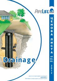
<strong>PVC</strong> KG ®<br />
PIPES FROM THREE-LAYER <strong>PVC</strong>-U<br />
FOR INFRASTRUCTURAL SEWERAGE<br />
www.pipelife.com
2<br />
Pipelife<br />
www.pipelife.com
CONTENTS<br />
1 INTRODUCTION ...................................................................................................................................... 4<br />
1.1 Why using three-layer pipe system? ........................................................................................................ 4<br />
1.2 Why unplasticized polyvinyl chloride? ..................................................................................................... 4<br />
2 APPLICATION ......................................................................................................................................... 4<br />
3 ADVANTAGES ......................................................................................................................................... 5<br />
4 STANDARDS ............................................................................................................................................ 6<br />
4.1 Why are the standards necessary? .......................................................................................................... 6<br />
4.2 Which standards and norms <strong>PVC</strong> KG System meets? ............................................................................ 6<br />
4.3 What do the standards require? ............................................................................................................... 6<br />
5 NOMENCLATURE ................................................................................................................................. 10<br />
5.1 Coextruded, three-layer, smooth surface <strong>PVC</strong>-KG pipes from unplasticized polyvinyl chloride<br />
manufactured in the town of Botevgrad ................................................................................................... 10<br />
5.2 <strong>PVC</strong> KG fittings according to BSS EN 13476-2 ...................................................................................... 11<br />
5.2.1 <strong>PVC</strong> KG Bend ......................................................................................................................................... 11<br />
5.2.2 <strong>PVC</strong> KG Reducer .................................................................................................................................... 11<br />
5.2.3 <strong>PVC</strong>-KG Tee 45° ..................................................................................................................................... 12<br />
5.2.4 <strong>PVC</strong> KG Tee 87°30’ .................................................................................................................................. 12<br />
5.2.5 <strong>PVC</strong> KG Socket plug ................................................................................................................................ 12<br />
5.2.6 <strong>PVC</strong> KG End cap ..................................................................................................................................... 13<br />
5.2.7 <strong>PVC</strong> KG Non-return valve (Anti flooding valve) ....................................................................................... 13<br />
5.2.8 <strong>PVC</strong> KG Sealing ring from SBR (styrene butadiene) ............................................................................... 13<br />
5.2.9 <strong>PVC</strong> KG Access pipe with threaded plug ................................................................................................. 13<br />
5.2.10 <strong>PVC</strong> KG Socket ........................................................................................................................................ 14<br />
5.2.11 <strong>PVC</strong> KG Double socket ............................................................................................................................ 14<br />
5.2.12 Lubricant .................................................................................................................................................. 14<br />
6 REQUIREMENTS FOR LAYING OF <strong>PVC</strong> KG PIPE SYSTEM ................................................................ 15<br />
6.1 General considerations ............................................................................................................................. 15<br />
6.2 Bedding characteristics ............................................................................................................................ 15<br />
6.2.1 Laying over existing untreated soil ............................................................................................................ 15<br />
6.2.2 Laying over artificial foundation ................................................................................................................ 15<br />
6.3 Filling around the pipe zone, backfill and final filling ................................................................................ 16<br />
6.3.1 Filling around the pipe zone and backfill .................................................................................................. 16<br />
6.3.2 Degree of backfill compaction .................................................................................................................. 17<br />
6.3.3 Final backfill ............................................................................................................................................ 17<br />
6.3.4 Compaction of the material for filling ....................................................................................................... 17<br />
6.3.5 Trench width ............................................................................................................................................ 17<br />
7<br />
7.1<br />
<strong>PVC</strong> KG PIPE SYSTEM ASSEMBLY ...................................................................................................... 18<br />
Joining of <strong>PVC</strong> KG pipes .......................................................................................................................... 18<br />
7.2 Cutting of <strong>PVC</strong> KG pipes. Chamfering of the spigot end of the shortened pipe ....................................... 19<br />
7.3 Joining to sewage collectors of <strong>PVC</strong> KG pipes ........................................................................................... 20<br />
7.4<br />
®<br />
Joining to PRO manholes ........................................................................................................................ 20<br />
8 TRANSPORTATION, LOADING AND UNLOADING, STORE ................................................................ 21<br />
9 HYDARAULIC DESING OF THE <strong>PVC</strong> KG SYSTEM .............................................................................. 22<br />
9.1 General assumptions ................................................................................................................................ 22<br />
9.2 Basic formulas .......................................................................................................................................... 22<br />
9.3 Software and hydraulic tables .................................................................................................................. 23<br />
9.4<br />
9.4.1<br />
Hydraulic nomographs ............................................................................................................................. 23<br />
A nomograph for hydraulic desing of circular pipes with partially full profile ............................................. 23<br />
9.4.2 Nomographs for hydraulic desing of non-pressure flow in circular <strong>PVC</strong> KG ® pipes with a full profile ...... 24<br />
9.5 Hydraulic Slopes and velocities of flow in <strong>PVC</strong> KG pipes ........................................................................ 25<br />
10 STATICS OF <strong>PVC</strong> KG SYSTEM .............................................................................................................. 26<br />
10.1 Interaction between the pipe and the surrounding soil ............................................................................. 26<br />
10.2 Load ......................................................................................................................................................... 27<br />
10.3 Types of soils according to ENV 1046 ..................................................................................................... 28<br />
10.4 Necessary data for statical calculation of the <strong>PVC</strong> KG pipe system ....................................................... 29<br />
Pipelife<br />
www.pipelife.com<br />
3
1 INTRODUCTION<br />
1.1 Why using three-layer pipe system?<br />
<strong>PVC</strong> KG pipe systems are distinguished with its specific structure made of internal and outer smooth layer and middle layer foam<br />
<strong>PVC</strong>. This structure allows with minimal costs of raw material, and low weight, to be achieved the necessary ring stiffness<br />
(SN≥2 kN/m 2 , SN≥4 kN/m 2 , SN≥8 kN/m 2 according to BSS ISO 9969).<br />
SN – (nominal ring stiffness)<br />
The unique characteristic of the structure is that it guarantees high ring elasticity and resistance to dynamic and static loads.<br />
1.2 Why unplasticized polyvinyl chloride?<br />
The unplasticized polyvinyl chloride (<strong>PVC</strong>-U) allows better hardness and stiffness of the product and reduces the risk of passing of<br />
harmful emissions of the material structure into the water, as it happens with the plasticized polyvinyl chloride for which part of the<br />
plastifiers can enter the water and thus pollute the environment. That is why the unplasticized polyvinyl chloride (<strong>PVC</strong>-U) is the natural<br />
choice for the manufacture of polyvinyl chloride infrastructural sewerage.<br />
2 APPLICATION<br />
<strong>PVC</strong> KG system is designed for gravity conveyance of:<br />
● Domestic,<br />
● Industrial,<br />
● Rain,<br />
● Mixed and<br />
● Drainage<br />
Waste waters<br />
<strong>PVC</strong> KG finds application in:<br />
● Electricity supplu and<br />
● Telecommunication<br />
As protective pipe system<br />
Indoor and underground sewerage systems, can be constructed by <strong>PVC</strong> KG pipes.<br />
4<br />
Pipelife<br />
www.pipelife.com
3 ADVANTAGES<br />
● Resistance to abrasion<br />
● Chemical resistance (from pH=2 to pH=12)<br />
● Resistance to high temperatures (40°C at constant flow and 60°C at short-term flow)<br />
● Impact resistance – according to the requirements of BSS EN 1411 and BSS EN 12061<br />
● Guaranteed stiffness SN≥2 kN/m 2 , SN≥4 kN/m 2 , SN≥8 kN/m 2 - according to the requirements of BSS ISO 9969<br />
● Easy transportation<br />
● Fast and easy installation<br />
● Easy cutting and cutting out<br />
● Injection molded sealing rings of SBR (styrene butadiene).<br />
● Guaranteed water-tightness of the system in the range of -0,3 bar to +0,5 bar according to the requirements of BSS EN 1277<br />
● Low weight<br />
● Long exploitation life<br />
● Low coefficient of hydraulic roughness – theoretical 0,0011 mm, exploitation 0,015 mm (does not include local resistances)<br />
● High hydraulic conductivity<br />
● Full range of connecting elements (fittings, manholes and facilities)<br />
● Compatibility with corrugated PP pipes Pragma through unique system of passages and adaptors.<br />
● Integrated part of the whole sewerage system of pipes, fittings and manholes and facilities<br />
● Pipes and fittings are with an integrated socket and elastomeric sealing ring<br />
● All the <strong>PVC</strong> KG system elements are manufactured under constant manufacture control of the raw material and the ready<br />
product.<br />
Pipelife<br />
www.pipelife.com<br />
5
4 STANDARDS<br />
4.1 Why are the standards necessary?<br />
The standards are a set of rules and norms based on practical and theoretical observations and studies about the technical parameters<br />
which the products should meet. They define minimal requirements for the quality of the specific product. At the same time they<br />
guarantee compatibility of the products manufactured by different manufacturers.<br />
All this makes the standard extremely important because it guarantees to all the parties: designers, engineers, architects, builders,<br />
clients, control authorities and others that the product which they use meets the specific applicaction and possesses all the qualities<br />
which allow unhindered, flawless and long exploitation.<br />
4.2 Which standards and norms <strong>PVC</strong> KG System meets?<br />
<strong>PVC</strong> KG system is manufactured and meets the requiremets of BSS EN 13476-2:2008<br />
„Plastics piping systems for non-pressure underground drainage and sewerage - Structured-wall piping systems of unplasticized<br />
poly(vinyl chloride) (<strong>PVC</strong>-U), polypropylene (PP) and polyethylene (PE) - Part 2: Specifications for pipes and fittings with smooth<br />
internal and external surface and the system, Type A”.<br />
It is applicable to the valid standards and norms for design of sewerage systems: „BSS EN 752:2008 Drain and sewer systems<br />
outside buildings” and „Norms for design of sewer systems” accepted with Order № RD-02-14-140 from 17. 04.1989, on the grounds<br />
of Art. 201, paragraph 1 of the local requirements, 9 and 10 from 1989 г., amended, local requirements, 1 from 1993.<br />
4.3 What do the standards require?<br />
The standard BSS EN 13476-2:2008 defines minimal requiremets for the multilayer pipe systems, concerning the following characteristics:<br />
► Ring stiffness. Tested according to BSS EN ISO 9969:2007<br />
TEST RESULT<br />
Force F<br />
Deflection<br />
The allowed stiffness are:<br />
SN≥2, SN≥4, SN≥8, SN≥16<br />
► Rring flexibility. Tested according to BSS EN ISO 13968:2008 (former ЕN 1446)<br />
The standard requires keeping the structure and the elasticity of the material during deformation of the ring up to 30%.<br />
Pipelife<br />
www.pipelife.com<br />
6
POSITIVE RESULT<br />
Force F<br />
10% 20% 30% Deflection<br />
NEGATIVE RESULT<br />
Force F<br />
F max<br />
10% 20% 30% Deflection<br />
► Creep ratio. Tested according to BSS EN ISO 9967<br />
Creeping is a deformation of plastics as a result of constant applied load. Creeping decreases for a period of two years.<br />
Creeping is critical or the watertightness of the socket connection.<br />
The standard requires creep ratio for <strong>PVC</strong>-U ≤ 2,5<br />
The creep ratio is inversely proportional to the elasticity module. The bigger is the elasticity module, the less is the creeping and vice<br />
versa.<br />
► Tolerances on pipe connections. Tested according to BSS EN 1401-1<br />
The basic geometrical characteristics are included in the standard BSS EN 13476. The proper sizes and tolerances assure all system<br />
elements to be the same, to fit each other and to allow reliable and safe assembly.<br />
This is also an important condition which concerns the connections with the elastomeric sealing ring. The pipes’ sizes and the fittings are<br />
defined in accordance with their outer diameter DN/OD or their inner diameter DN/ID. The standard BSS EN 13476 defines the following<br />
nominal diameters.<br />
DN/OD [mm]: 110, 125, 160, 200, 250, 315, 400, 500, 630, 800, 1000, 1200<br />
According to the diameter, the standard defines the walls thickness of the smooth ends of the pipes, the sockets and the inner layers,<br />
as well as the length of each product. The tolerances stated in the standard describe mainly and only the limit value, namely minimum<br />
and maximum.<br />
► Impact resistance. Tested according to BSS EN 744, BSS EN 1411, BSS EN 12061<br />
This test checks if the pipes and the fittings will be damaged during transportation, storage and assembly.<br />
According to the standard BSS EN 13476-part 2, there is one basic requirement: TIR ≤ 10% at<br />
temperature 0°С and at temperature -10°С.<br />
The point of damage is assessed as a real impact norm [TIR - true impact rate] for the lot or the production where the maximum value<br />
for TIR is 10% [TIR = the total number of damages divided by the total number of impacts as a percentage as if the whole lot has<br />
been tested].<br />
Pipelife<br />
www.pipelife.com<br />
7
► Watertightness of connections with spigot socket. Tested according to BSS EN 1277<br />
This method tests the ability of the system to keep the liquids from and out of the system (filtration/infiltration). The test confirms the<br />
connection between the soft end the spigot socket and the socket. The watertightness of the system has an impact on the ecological<br />
aspect of the soil and the waters.<br />
The standard requires watertightness of the connections<br />
from -0,3 bar negative pressure<br />
to +0,5 bar positive pressure.<br />
The connections are tested at extreme conditions, including connections at angle and diameter deviation of the ring from negative to<br />
positive state. For the rain and the sewerage pipe systems this is one of the fundamental charactiristics.<br />
► Mechanical strength or flexibility of fabricated fittings. Tested according to BSS EN 12256<br />
The standard defines the mechanical strength of the fittings as certain force is applied (F), at certain distance (L) from the fitting, the<br />
displace (A) must remain within the range of 170 mm withoutbreaking the integrity of the fitting at critical point (C).<br />
A<br />
B<br />
C<br />
displacement<br />
fixture<br />
critical point<br />
Nominal diameter<br />
DN/OD 1)<br />
mm<br />
Minimal<br />
moment<br />
kN.m (FxL)<br />
Minimal<br />
displacement<br />
mm (A)<br />
110 0,20 170<br />
125 0,29 170<br />
160 0,61 170<br />
200 1,20 170<br />
250 2,30 170<br />
315 3,10 170<br />
355 3,50 170<br />
400 4,00 170<br />
450 4,50 170<br />
500 5,00 170<br />
630 6,30 170<br />
710 7,10 170<br />
800 8,00 170<br />
900 9,00 170<br />
1000 10,00 170<br />
1) For DN/ID fittings, the test is conducted as the parameters are used<br />
special for the next bigger DN/OD diameter, instead of the outer diameter<br />
of the specific DN/ID diameter.<br />
► Resistance to high temperatures. Tested according to BSS EN 1437 and BSS EN 1055<br />
During exploitation the thermoplastic pipe systems for drainage and public sewerage must be resistant to specific temperatures of<br />
waste waters. Due to this reason, the systems made of thermoplastic must be resistant to the temperatures given below when laid in<br />
the ground outside buildings.<br />
Accordin to the empiric studies of TEPPFA (The European Plastic Pipes and Fittings Association) they are:<br />
Long lasting temperature of the water of 45°С for dimensions ≤ 200 мм<br />
Long lasting temperature of the water of 35°С for dimensions >200 мм<br />
Due to the fact that these type pipe systems can be buried in basements or installed at distance of 1 m around the buildings, they must<br />
be resistant to maximal short-term flows of waste water with temperature of up to 60°С.<br />
8<br />
Pipelife<br />
www.pipelife.com
► Longitudinal shrinking. Tested according to BSS EN ISO 2505:2006<br />
Of the three types thermoplastic materials (PE, PP и <strong>PVC</strong>-U), the pipe systems of unplasticized polyvinyl chloride (<strong>PVC</strong>-U) for drainage<br />
and public sewerage are the most sensitive to longtitudinal deformations as a result of differences in the temperature of the fluid and of<br />
the the environment. Due to this reason the <strong>PVC</strong>-U systems shrink longtitudinally.<br />
On a test pipe are made two parallel lines, as the distance between them is measured before and after heating in a<br />
drying room at 150°С.<br />
The longtitudinal shrinking must be ≤5%.<br />
Meeting the requirement for longtitudinal shrinking guarantees that the <strong>PVC</strong>-U pipes even after shrinking won’t come out of the socket<br />
connections and the watertightness of the system won’t be compromised.<br />
Pipelife<br />
www.pipelife.com<br />
9
5 NOMENCLATURE<br />
5.1 Coextruded, three-layer, smooth surface <strong>PVC</strong>-KG pipes from unplasticized polyvinyl<br />
chloride manufactured in Botevgrad<br />
Nominal<br />
roughness<br />
(stiffness) of<br />
the pipe’s ring<br />
SN<br />
Nominal<br />
diamter<br />
DN/OD<br />
Outer<br />
diameter<br />
D out<br />
Inner<br />
diameter<br />
D in<br />
Wall<br />
thickness<br />
S<br />
Effective length of the pipe<br />
L effect<br />
kN/m 2 mm mm mm mm 0,5 m 1 m 2 m 3 m 5 m<br />
Package<br />
pipes/pallet<br />
Package<br />
pipes/truck<br />
SN≥2 kN/m 2 200 200 192,2 3,9 yes yes yes yes yes 20 240<br />
110 110 105,6 2,2 yes yes yes yes yes 60 720<br />
160 160 153,6 3,2 yes yes yes yes yes 49 392<br />
250 250 240,2 4,9 yes yes yes yes yes 12 144<br />
315 315 302,6 6,2 yes yes yes yes yes 12 102<br />
SN≥4 kN/m 2 160 160 152,0 4,0 yes yes yes yes yes 49 392<br />
200 200 190,2 4,9 yes yes yes yes yes 20 240<br />
110 110 103,6 3,2 yes yes yes yes yes 60 720<br />
125 125 118,6 3,2 yes yes yes yes yes 54 648<br />
250 250 237,6 6,2 yes yes yes yes yes 12 144<br />
315 315 299,6 7,7 yes yes yes yes yes 12 102<br />
SN≥8 kN/m 2 200 200 188,2 5,9 yes yes yes yes yes 49 392<br />
110 110 103,6 3,2 yes yes yes yes yes 60 720<br />
160 160 150,6 4,7 yes yes yes yes yes 49 392<br />
250 250 235,4 7,3 yes yes yes yes yes 20 240<br />
315 315 296,6 9,2 yes yes yes yes yes 20 240<br />
D out<br />
S<br />
D in<br />
Outside smooth<br />
layer from <strong>PVC</strong>-U<br />
Middle layer from<br />
foam <strong>PVC</strong>-U<br />
Inside smooth<br />
layer from <strong>PVC</strong>-U<br />
S<br />
L effect<br />
Pipelife<br />
www.pipelife.com<br />
10
5.2 <strong>PVC</strong> KG fittings according to BSS EN 13476-2<br />
5.2.1 <strong>PVC</strong> KG Bend<br />
d n<br />
[mm]<br />
α<br />
(°)<br />
Z 1<br />
[mm]<br />
Z 2<br />
[mm]<br />
t<br />
[mm]<br />
A<br />
[mm]<br />
Product code<br />
110 15 9 12 70 70 KGB110x15<br />
110 30 17 23 70 70 KGB110x30<br />
110 45 60 60 70 70 KGB110x45<br />
110 87 60 66 70 70 KGB110x87<br />
160 15 22 29 84 84 KGB160x15<br />
160 30 33 44 84 84 KGB160x30<br />
160 45 45 56 84 84 KGB160x45<br />
160 87 95 106 84 84 KGB160x87<br />
200 15 25 34 124 124 KGB200x15<br />
200 30 40 50 124 124 KGB200x30<br />
200 45 56 65 124 124 KGB200x45<br />
200 87 115 118 124 124 KGB200x87<br />
250 15 153 32 130 135 KGB250x15<br />
250 30 205 84 130 135 KGB250x30<br />
250 45 261 140 130 135 KGB250x45<br />
250 87 483 363 130 135 KGB250x87<br />
315 15 179 39 138 155 KGB315x15<br />
315 30 244 104 138 155 KGB315x30<br />
315 45 315 174 138 155 KGB315x45<br />
315 87 595 455 138 155 KGB315x87<br />
400 15 208 49 150 176 KGB400x15<br />
400 30 291 131 150 176 KGB400x30<br />
400 45 380 220 150 176 KGB400x45<br />
400 87 734 575 150 176 KGB400x87<br />
5.2.2 <strong>PVC</strong> KG Reducer<br />
d 1 / d 2<br />
[mm]<br />
Z 1<br />
[mm]<br />
t<br />
[mm]<br />
Product code<br />
160/110 140 70 KGR160/110<br />
200/160 145 84 KGR200/160<br />
250/200 185 165 KGR250/200<br />
315/250 330 183 KGR315/250<br />
400/315 415 205 KGR400/315<br />
Pipelife<br />
www.pipelife.com<br />
11
5.2.3 <strong>PVC</strong>-KG Tee 45°<br />
d n / d 1<br />
[mm]<br />
Z 1<br />
[mm]<br />
Z 2<br />
[mm]<br />
Z 3<br />
[mm]<br />
t 1<br />
[mm]<br />
t 2<br />
[mm]<br />
A<br />
[mm]<br />
Product code<br />
110/110 38 133 133 70 70 70 KGEA110/110x45<br />
160/110 57 163 170 84 70 84 KGEA160/110x45<br />
160/160 92 205 205 84 84 84 KGEA160/160x45<br />
200/110 35 201 165 124 70 124 KGEA200/110x45<br />
200/160 93 239 211 124 84 124 KGEA200/160x45<br />
200/200 124 236 236 124 124 124 KGEA200/200x45<br />
250/110 153 370 305 130 87 135 KGEA250/110x45<br />
250/160 153 340 305 130 107 135 KGEA250/160x45<br />
250/200 153 320 305 130 130 135 KGEA250/200x45<br />
250/250 158 335 335 138 138 138 KGEA250/250x45<br />
315/110 179 460 373 138 87 155 KGEA315/110x45<br />
315/160 179 430 373 138 107 155 KGEA315/160x45<br />
315/200 179 410 373 138 130 155 KGEA315/200x45<br />
315/250 179 383 373 138 130 155 KGEA315/250x45<br />
315/315 201 438 438 154 154 154 KGEA315/315x45<br />
400/110 208 582 464 150 87 176 KGEA400/110x45<br />
400/160 208 552 464 150 107 176 KGEA400/160x45<br />
400/200 208 532 464 150 130 176 KGEA400/200x45<br />
400/250 208 510 464 150 130 176 KGEA400/250x45<br />
400/315 208 487 464 150 138 176 KGEA400/315x45<br />
400/400 318 588 548 189 189 189 KGEA400/400x45<br />
5.2.4 <strong>PVC</strong> KG Tee 87°30’<br />
d n / d 1<br />
[mm]<br />
110/110 250/160 315/315<br />
160/110 250/200 400/110<br />
160/160 250/250 400/160<br />
200/110 315/110 400/200<br />
200/160 315/160 400/250<br />
200/200 315/200 400/315<br />
250/110 315/250 400/400<br />
5.2.5 <strong>PVC</strong> KG Socket plug<br />
d n<br />
[mm]<br />
d 1<br />
[mm]<br />
А<br />
[mm]<br />
L<br />
[mm]<br />
Product code<br />
110 126 43 47 KGM110<br />
160 180 53 58 KGM160<br />
200 220 63 68 KGM200<br />
250 280 89 96 KGM250<br />
315 345 92 101 KGM315<br />
Pipelife<br />
www.pipelife.com<br />
12
5.2.6 <strong>PVC</strong> KG End cap<br />
d n<br />
d n<br />
[mm]<br />
L<br />
[mm]<br />
Product code<br />
110 46 KGK110<br />
160 54 KGK160<br />
200 65 KGK200<br />
250 – KGK250<br />
315 – KGK315<br />
400 – KGK400<br />
L<br />
5.2.7 <strong>PVC</strong> KG Non-return valve (Anti flooding valve)<br />
d n<br />
[mm]<br />
t<br />
[mm]<br />
A<br />
[mm]<br />
L<br />
[mm]<br />
H<br />
[mm]<br />
Product code<br />
110 61 61 307 230 KGKLAP110<br />
160 74 74 337 255 KGKLAP160<br />
200 86 100 451 300 KGKLAP200<br />
5.2.8 <strong>PVC</strong> KG Sealing ring from SBR (styrene butadiene)<br />
DN<br />
[mm]<br />
Product code<br />
110 KGKseal110<br />
125 KGKseal125<br />
160 KGKseal160<br />
200 KGKseal200<br />
250 KGKseal250<br />
315 KGKseal315<br />
400 KGKseal400<br />
5.2.9 <strong>PVC</strong> KG Access pipe with threaded plug<br />
d n<br />
[mm]<br />
Z 1<br />
[mm]<br />
Z 2<br />
[mm]<br />
t<br />
[mm]<br />
A<br />
[mm]<br />
D 1<br />
[mm]<br />
Product code<br />
110 210 65 70 70 102 KGRE110<br />
160 260 90 84 84 151 KGRE160<br />
200 358 110 165 165 193 KGRE200<br />
250 468 235 183 183 191 KGRE250<br />
315 490 235 205 205 191 KGRE315<br />
400 519 235 324 234 191 KGRE400<br />
Pipelife<br />
www.pipelife.com<br />
13
5.2.10 <strong>PVC</strong> KG Socket<br />
d n<br />
[mm]<br />
L<br />
[mm]<br />
Product code<br />
110 120 KGU110<br />
160 180 KGU160<br />
200 199 KGU200<br />
250 265 KGU250<br />
315 320 KGU315<br />
400 330 KGU400<br />
5.2.11 <strong>PVC</strong> KG Double socket<br />
d n<br />
[mm]<br />
L<br />
[mm]<br />
Product code<br />
110 120 KGMM110<br />
160 206 KGMM160<br />
200 199 KGMM200<br />
250 245 KGMM250<br />
315 350 KGMM315<br />
400 400 KGMM400<br />
5.2.12 Lubricant<br />
Weight<br />
[mg]<br />
Product code<br />
250 MGN250<br />
2000 MGN2000<br />
Pipelife<br />
www.pipelife.com<br />
14
6 REQUIREMENTS FOR LAYING OF <strong>PVC</strong> KG PIPE SYSTEM<br />
6.1 General considerations<br />
The most important factor for achieving<br />
of good assembly of plastic collector is<br />
the interaction between the pipe and the<br />
surrounding soil. The bigger value of the<br />
pipe resistance is achieved from the soil<br />
at the lower part of the pipe horizontally<br />
in both directions. Therefore the type of<br />
the backfill and the degree of compaction<br />
in the pipe zone are very important.<br />
Therefore for every sewage project the<br />
engineer must define the conditions for<br />
laying like:<br />
1. Conditions of the existing soil layers<br />
and the suitability for their usage for<br />
trench basis and backfill.<br />
2. Geotechnical characteristics of the<br />
soil used for bedding and backfill and the<br />
way they are made.<br />
3. The appropriate type of strength of<br />
the pipe. At the very beginning of every<br />
project, the first step is to be made<br />
geotechnical study of the layers in which<br />
the pipe will be laid. This study and the<br />
lab tests must be conducted in order to<br />
be established the type of the soil and<br />
its structure, the degree of compaction<br />
and the level of the underground waters.<br />
6.2 Bedding characteristics<br />
The design of the bedding depends on<br />
the geotechnical characteristics of the<br />
soil in the zone where the pipe is laid.<br />
Generally there are two types of choice of<br />
bedding: natural laying over the existing<br />
soil layer without additional treatment and<br />
6.2.1 Laying over existing, untreated soil<br />
In some cases can be allowed laying<br />
of <strong>PVC</strong> KG pipes on the bottom of a<br />
trench but only on grainy,dry soil which is<br />
without middle and big stones (> 20mm).<br />
These soils are fine gravel, big sand,<br />
fine sand and sandy clays. Under these<br />
conditions the pipe is laid on thin (10 to<br />
15cm) non-compacted bedding directly on the<br />
bottom of the trench. The purpose of the<br />
bedding is to improve the conditions for<br />
laying on the bottom of the trenchand to<br />
provide secure support of the pipe with a<br />
range of angle of laying α = 60-180° (see<br />
Figure 6.1)<br />
laying over bedding made of selected<br />
soil material with the necessary degree<br />
of sealing.<br />
Figure 6.1 Laying in natural conditions<br />
6.2.2 Laying over artificial foundation<br />
In some situations the pipe must be laid<br />
over additionally made foundation:<br />
1. When the natural soil can serve as<br />
a foundation but due to structural<br />
damages can’t fulfil this function.<br />
2. In rocky soils, cohesive soils (clays)<br />
and alluvium soils.<br />
3. In weak soft soils like organic<br />
alluvium and peat.<br />
4. In all the other cases when the<br />
design documentation requires additional<br />
bedding to be made.<br />
An example for solution of case 1 and 2<br />
is shown on Figure 6.2. The pipeline is<br />
laid over two two layers made of sandy<br />
soils or fine gravels with a maximal size<br />
of the grains 20 mm.<br />
● The founding layer is prepared from<br />
well compacted soils with a depth of 25<br />
cm (minimum 15 cm).<br />
● The bedding is from 10 to 15 cm –<br />
thick non-compacted.<br />
In cases of weak soils, depending on the<br />
thickness of the layer, under the level of<br />
laying of the sewage pipe are offered two<br />
solutions.<br />
1. When the thickness of the weak<br />
layer is ≤ 1,0 m (see Figure 6.3).<br />
In this case the layer weak soil is taken<br />
and in the trench is placed new well<br />
compacted mixture of crushed gravel<br />
and sand (in proportion 1:0,3) or mixture<br />
of natural gravel and crushed gravel (in<br />
proportion 1:0,3).<br />
This new founding layer is laid over<br />
geotextile.<br />
2. When the thickness of the weak<br />
layer is > 1,0 m (see Figure 6.4)<br />
In this case a new additional 25 cm<br />
layer well compacted mixture of crushed<br />
gravel and sand (in proportion 1:0,6) or<br />
mixture of natural gravel and sand (in<br />
proportion 1:0,3). This new layer is laid<br />
over geotextile.<br />
Pipelife<br />
www.pipelife.com<br />
15
Figure 6.2 An example for laying in<br />
stable soil<br />
Figure 6.3 An example for laying in<br />
weak soil loess at depth ≤ 1.0 m<br />
In all cases the compacting of the founding<br />
layer must be from 85% to 95% according<br />
to Proctor<br />
Figure 6.4 An example for laying in<br />
weak soil loess at depth > 1.0 m<br />
0 – additional 25 cm founding layer of<br />
crushed gravel and sand or natural gravel<br />
and crushed gravel<br />
1 – founding layer of crushed gravel and<br />
sand or natural gravel and sand<br />
2 – bedding<br />
3 – geotextile<br />
6.3 Filling around the pipe zone, backfill and final filling<br />
Besides the founding layer and the bedding, the type of the soil and its density matters and is important for achieving of satisfactory<br />
level of assembly of the flexible pipes.<br />
6.3.1 Filling around the pipe zone and backfill<br />
The criterion for selection of appropriate<br />
material suitable for using for filling the<br />
pipe zone around the pipe and directly<br />
above the crown of the pipe to the surface<br />
of the trench is based on achieving of<br />
optimal resistance and stiffness of the<br />
soil after the compaction.<br />
a – basic filling<br />
b – earth covering<br />
Figure 6.5 pipeline section<br />
c – zone around the pipe<br />
d – bedding (if required)<br />
e – founding layer (if required<br />
The appropriate soil material includes<br />
most types and classes natural<br />
granulated materials with maximal<br />
size of the grains not more than 10%<br />
of the nominal diameter of the pipe but<br />
not more than 60 mm. The material for<br />
backfill must not contain foreign materials<br />
(admixtures) like snow, ice or frozen soil<br />
lumps.<br />
Table 3.1 Characteristics of the materials<br />
for filling around the pipe and backfill<br />
Material<br />
Gravel,<br />
Crushed stones<br />
FILLING AROUND THE PIPE ZONE AND FOLLOWING BACKFILL<br />
Particles diameter<br />
[mm]<br />
8-22, 4-16<br />
8-12, 4-8<br />
Gravel 2-20<br />
Sand,<br />
Moraine gravel<br />
0.2-20<br />
Notes<br />
The most appropriate soil material, maximum<br />
from 5 to 20% particles with size of 2 mm<br />
Appropriate soil material, maximum from 5 to<br />
20% particles with size of 0.2 mm<br />
Relatively appropriate soil material, maximum up<br />
to 5% particles with size of 0.02 mm<br />
Pipelife<br />
www.pipelife.com<br />
16
6.3.2 Degree of backfill compaction<br />
The necessary degree of sealing of<br />
the backfill depends on the loading<br />
conditions.<br />
● For road surface the mimimum<br />
compaction of the soil in the pipe zone is<br />
95%<br />
● Outside the road surface the filling<br />
must be compacted to:<br />
- 85% if the depth is < 4.0 m<br />
- 95% if the depth is ≥ 4.0 m<br />
The material of the backfill must be<br />
compacted on layers with a thickness of<br />
10 to 30 cm.<br />
The height of the backfill above the<br />
crown of the pipe must be:<br />
● minimum 15 cm for pipe with a<br />
diameter D < 400 mm<br />
● minimum 30 cm for pipe with a<br />
diameter D ≥ 400 mm<br />
6.3.3 Final backfill<br />
The material of the final backfill of the<br />
trench can be dug soil if possible the<br />
achievement of maximal size of the<br />
particles of 30 mm. For sewers with a<br />
diameter D < 400 mm and basic filling<br />
with a depth of 15 cm, the material of the<br />
final backfill must not contain particles<br />
bigger than 60 mm.<br />
For road surfaces the minimum compaction<br />
of the final backfill must be 95%.<br />
6.3.4 Compaction of the material for filling<br />
The requirements for the degree of<br />
compaction depend on the general load<br />
and must be stated in the design<br />
documentation. Depending on the<br />
equipment, the thickness of the layers<br />
and the ability of the soil for compaction,<br />
different degrees of compaction can be<br />
achieved. In Table 3.2 are given data<br />
which are applicable to gravel, sand, clay<br />
and alluvium soils.<br />
Table 3.2 Compaction methods<br />
6.3.5 Trench width<br />
Equipment<br />
The trench width must allow the proper spreading and compaction of the filling material. The minimum width of the zone on both<br />
sides of the pipe for laying of the filling is b=30 cm. Therefore the mimimum trench width (B) on the level of the pipe’s crown is:<br />
min<br />
B = D + (2 x b min )<br />
If the resistance of the soil foundation is smaller than the predetermined, the trench width must be:<br />
B ≥ 4 x d n<br />
Similar situation can be achieved with grain soils with low density (I D < 0.33) иor soils with limit I L > 0.0.<br />
The necessary filling for achieving the desired angle of laying<br />
Weight<br />
[kg]<br />
Maxumum thickness<br />
of the layer before the<br />
compaction [m]<br />
gravel,<br />
sand<br />
Compaction methods<br />
clay,<br />
alluvium<br />
Minimum<br />
thickness of<br />
the first filling<br />
above the<br />
pipe<br />
[m]*<br />
Number of repetitions for achieving the<br />
sealing<br />
85%<br />
according<br />
to Proctor<br />
modified test<br />
90%<br />
according<br />
to Proctor<br />
modified test<br />
95%<br />
according<br />
to Proctor<br />
modified test<br />
Fine treading - 0.10 - - 1 3 6<br />
Manual<br />
compaction<br />
Vibration<br />
compaction<br />
Separate<br />
mechanical<br />
compaction**<br />
Mechanized<br />
compaction<br />
min. 15 0.15 0.10 0.30 1 3 6<br />
50-100 0.30 0.20-0.25 0.50 1 3 6<br />
50-100 0,20 - 0.50 1 4 7<br />
50-100<br />
100-200<br />
400-600<br />
* before using tools for compaction<br />
** compaction on both sides of the pipe<br />
-<br />
-<br />
0.20<br />
0.50<br />
0.40<br />
0.80<br />
1<br />
1<br />
1<br />
4<br />
4<br />
4<br />
7<br />
7<br />
7<br />
D out<br />
Bedding angle 2 α<br />
DN D out<br />
60° 90° 120°<br />
[mm] [mm]<br />
h 2α [cm]<br />
180°<br />
DN/OD160 160 1 2 4 8<br />
DN/OD200 200 1 3 5 10<br />
DN/OD250 250 2 4 6 12<br />
DN/OD315 315 2 5 8 16<br />
Pipelife<br />
www.pipelife.com<br />
17
7 <strong>PVC</strong> KG PIPE SYSTEM ASSEMBLY<br />
7.1 Joining of <strong>PVC</strong> KG pipes<br />
<strong>PVC</strong> KG pipe <strong>PVC</strong> KG Tee <strong>PVC</strong> KG pipe<br />
Pragma ® pipe<br />
Assembly click-ring<br />
with a sealing<br />
<strong>PVC</strong> KG pipe<br />
<strong>PVC</strong> KG pipe<br />
<strong>PVC</strong>-U <strong>PVC</strong> KG<br />
Adaptor to <strong>PVC</strong><br />
Pragma ® pipe<br />
Pipelife<br />
www.pipelife.com<br />
18
Take out the rubber sealing from the<br />
socket. Clean with a dry cloth the rubber<br />
sealing and socket groove. Put lubricant on<br />
the spigot of the pipe.<br />
Mark the spot where the pipe must enter<br />
into the socket. After that carefully insert<br />
the pipe in the socket with a rotating<br />
movement.<br />
When the diameters or the lengths of the<br />
pipes are big, a lever can be used. In this<br />
case put a wooden block in the socket in<br />
order to avoid the direct contact with the<br />
lever and possible breaking.<br />
7.2 Cutting of <strong>PVC</strong> KG pipes. Chamfering of the spigot end of the shortened pipe<br />
On the construction site sometimes it is necessary shortening of the pipe’s length. On the figures below is shown how it is made and<br />
what additional actions are necessary.<br />
Cutting of a pipe. The pipe can be cut with a<br />
hand-saw or with a cutting machine. Before<br />
cutting the pipe must be fixed.<br />
The spigot end of the short pipe must<br />
be chamfered at and angle of 15° in order<br />
to fit tight to the internal side of the<br />
socket. Chamfering can be done with<br />
sandpaper, filer grinding machine.<br />
A diagram of chamfering of spigot<br />
shortened pipe<br />
Pipelife<br />
www.pipelife.com<br />
19
7.3 Joining to sewage collectors from <strong>PVC</strong> KG pipes<br />
Joining to sewage collectors from <strong>PVC</strong> KG pipes is made by two basic ways:<br />
● Joining with tee and bend (see 5.2.2 and 5.2.3). It is recommended for joining to a newly laid collector which has<br />
not been exploited yet.<br />
● Joining with saddle with a screw or with in-situ connection (see 5.2.9 and 5.2.11). It is recommended for joining to an already<br />
existing collector which is already in exploitation.<br />
● In both of the above mentioned cases it is recommended joining to the collector to be made in the upper third of the<br />
collector section at an angle φ with regard to the vertical axis of the collector. Depending on the situation of the collector and<br />
the conected lateral sewer there are three basic ways:<br />
Figure 7.1 Joining of lateral sewer to collector<br />
Figure 7.2 Joining of lateral sewer to collector in case of displacement<br />
Figure 7.3 Joining of lateral sewer to collector in case of displacement and obstacle<br />
7.4 Joining to PRO® manholes<br />
Pipelife PRO® manholes are designed and manufactured for safe and secure joint with the <strong>PVC</strong> KG pipes and the fittings.<br />
20<br />
Pipelife<br />
www.pipelife.com
8 TRANSPORTATION, LOADING AND UNLOADING, STORE<br />
Wrong transportation (as well as wrong storage) can lead to deformations or damages of the pipes, the fittings and the sealing rings<br />
which can create problems during laying and functioning of the mounted pipes.<br />
The pipes must be transported in vehicles with smooth clean load surface i.e. without unevenness or for example protruding<br />
nails. The pipes must lay with its whole length on the floor (see Figure 8.1).<br />
Harsh lifting and dropping of the pipes must be avoided during loading and unloading. Their throwing and manual unloading is<br />
unacceptable (see Figure 8.4). For mechanized loading and unloading of pipes packed in the plant, it must be used appropriate lifting<br />
devices for example engine truck or crane.<br />
The pipes must be stored on smooth surface, as the allowed height is from 2.0 [m] to 3.0 [m] (for pipes in pallets). When storing free<br />
pipes the allowed height is up to 1.0 [m]. It is recommended the arrangement of the pipes during transportation and during storage to<br />
be in both directions – on two adjacent lines the socket (respectively spigot) ends to point in opposite directions (see Figure 8.5).<br />
Thus the loading between the different lines of pipes is even and it is not necessary to put additional wooden supports between the<br />
lines. The wooden supports are placed only under the lowest line. The pipe must lay at least on three wooden supports with minimum<br />
width of 10 [cm].<br />
The pipes of the <strong>PVC</strong> KG pipe system can be stored on open space. They endure the influence of the UV rays minimum two years as<br />
they retain the physical-mechanical properties unchanged, regardless of the change in the colour (fading)<br />
Correct<br />
Wrong<br />
Transportation<br />
Figure 8.1 Figure 8.2<br />
Unloading<br />
Figure 8.3 Figure 8.4<br />
Storage<br />
Figure 8.5<br />
Pipelife<br />
www.pipelife.com<br />
21
9 HYDARAULIC DESING OF THE <strong>PVC</strong> KG SYSTEM<br />
9.1 General assumptions<br />
A hydraulic design concerns selecting<br />
parameters for gravity flow sewers, which<br />
normally do no flow full. The objective<br />
of hydraulic design is to determine the<br />
most economic pipe diameter at which<br />
the required discharge is passed. In<br />
practice, computation of hydraulic pipe<br />
parameters are based on the following<br />
9.2 Basic formulas<br />
In practice, for computational purposes,<br />
the following semi-empirical equations<br />
are used:<br />
assumptions:<br />
1. The assumption of a continuous<br />
flow, meaning:<br />
● the depth (h), flow area (f) and<br />
velocity (v) at every cross-section remain<br />
constant at the whole considered pipe<br />
section;<br />
● the energy grade line, water surface<br />
and pipe bottom slope are parallel.<br />
2. In the pipe system, the flow regime<br />
is turbulent.<br />
where:<br />
Q – flow rate, [m 3 /s]<br />
V – average flow Velocity, [m/s]<br />
F – flow area, [m 2 ]<br />
Friction losses on the pipe lenght are<br />
calculated based on the initial hydraulic<br />
gradient. Initial hydraulic gradient for<br />
closed pipes with a turbulent<br />
flow is calculated based on Darcy-<br />
Weisbach formula:<br />
Darcy friction factor ( λ) is<br />
calculated based on Colebrook-White<br />
formula:<br />
where:<br />
i – hydraulic gradient, [m/m]<br />
d – inner diameter of the pipe, [m]<br />
V – average flow velocity, [m/s]<br />
g – acceleration of gravity, [m/s 2 ]<br />
λ – Darcy friction factor<br />
Re – Reynold number<br />
ν – coefficient of kinematic viscosity [m 2 /s]<br />
(for water at temp 10°C ν = 1,308x10 -6 [m 2 /s])<br />
k – coefficient of absolut roughness, [mm]<br />
The Bretting formula for pipes flowing<br />
partly full:<br />
where:<br />
Q – flow rate in the pipe flowing full, [m 3 /s]<br />
q п – flow rate in the pipe flowing partly<br />
full, [m 3 /s]<br />
h п – actual depth of flow, [m]<br />
d – inner diameter of the pipe, [m]<br />
Ratio of absolute pipe wall – k, [mm]<br />
Laboratory roughness<br />
0,0011 [mm]<br />
Pipe roughness in exploitation (without regard of the local resistance) 0,015 [mm]<br />
Artificially increased roughness with regard to the local resistances at main sewage collectors<br />
Artificially increased roughness with regard to the local resistances at secondary sewage collectors<br />
The values of the artificially increased roughness are recommended but not compulsory. The designers can choose another<br />
artificially increased value of K or another method for calculation of local resistances.<br />
0,25 [mm]<br />
0,40 [mm]<br />
22<br />
Pipelife<br />
www.pipelife.com
9.3 Software and hydraulic tables<br />
Besides the following nomographs Pipelife offers to the designers other helpful tools for hydraulic desing. In the “For the designer”<br />
section in www.pipelife.bg can be found and used a web software for hydraulic calculation of a particular sewage section, a software<br />
for hydraulic calculation of the sewage network and hydraulic tables for filling h/D=0.5, h/D=0.7 и h/D=1.0<br />
9.4 Hydraulic nomographs<br />
9.4.1 A nomograph for hydraulic design of circular pipes with partially full profile<br />
correlation between the flow depth and the pipe diameter (d)<br />
correlation between the actual flow with filling (h n ) and outflow for full profile<br />
correlation between the actual velocity with filling (h n ) and velocity for full profile<br />
correlation between the hydraulic radius with filling (h n ) and hydraulic radius for full profile<br />
Pipelife<br />
www.pipelife.com<br />
23
9.4.2 Nomographs for hydraulic desing of non-pressure flow in circular <strong>PVC</strong> KG ® pipes with a full profile<br />
For k = 0.015 [mm], water temperature t = 10°C, full profile<br />
Darcy-Weisbach/Colebrook-White Formula<br />
Quantity - Q [L/s]<br />
hydraulic slope [m/km]<br />
Velocity - V [m/s]<br />
For k = 0.25 [mm], water temperature t = 10°C, full profile<br />
Darcy-Weisbach/Colebrook-White Formula<br />
Quantity - Q [L/s]<br />
hydraulic slope [m/km]<br />
Velocity - V [m/s]<br />
Pipelife<br />
www.pipelife.com<br />
24
For k = 0.40 [mm], water temperature t = 10°C, full profile<br />
Darcy-Weisbach/Colebrook-White Formula<br />
Quantity - Q [L/s]<br />
hydraulic slope [m/km]<br />
Velocity - V [m/s]<br />
9.5 Hydraulic Slopes and velocities of flow in <strong>PVC</strong> KG pipes<br />
The minimum sewer slope is required<br />
to achieve the lowest flow velocity which<br />
will prevent suspended solids from<br />
settling out and clogging the pipe.<br />
The selfcleaning flow which prevents<br />
sedimentation of particles on the bottom<br />
of the pipe depends on the internal<br />
friction angle Θ (see Figure 9.1).<br />
Θ is calculated by formula 5).<br />
where:<br />
hn – depth of flow, [m]<br />
d – inside pipe diameter, [m]<br />
Θ - internal friction angle, [°]<br />
If Θ = 35°<br />
then hn/d = 0,1<br />
The area of deposition may be allowed<br />
to a relatively flat zone of the channel<br />
bottom.<br />
Figure 9.1.<br />
Angle of friction<br />
The safe lower limit of velocity which Usually, the permissible minimum V sc = 0,8 m/s for sanitary sewers<br />
prevents sedimentation depends on<br />
the type of sediments.<br />
velocities (V sc ) which ensure selfcleaning<br />
of the sewer should not be, at full flow,<br />
V sc = 0,6 m/s for storm sewers<br />
Vsc<br />
= 1,0 m/s for combined sewers<br />
lower than:<br />
Pipelife<br />
www.pipelife.com<br />
25
When determining the slope of<br />
the pipeline, one should select the<br />
permissible velocities taking into account<br />
the pipe diameter. To this end, a simple<br />
formula can be used: 6)<br />
where:<br />
i min = minimum permissible slope<br />
d = internal pipe diameter<br />
The minimum slope of the sewer pipeline<br />
can also be expressed by the tractive<br />
force (t), given as: 7)<br />
where:<br />
γ = specific weight of waste water, [kg/m 3 ]<br />
R = hydraulic radius, [m]<br />
i = hydraulic slope, [m/m]<br />
The actual tractive force is: 8)<br />
From the above, the critical tractive force<br />
for the actual depth of flow (hn) is: 9)<br />
where:<br />
hidraulic radius for circual full<br />
flow pipe<br />
k 1 = correction factor,<br />
The critical tractive force which fulfil the<br />
condition of the sewer self-cleaning is:<br />
10)<br />
Thus, from Equation 9, after rearranging,<br />
the minimum slope of the pipe is: 10a)<br />
(for storm water)<br />
(for storm water)<br />
(for sewage)<br />
(for sewage)<br />
10 STATICS OF <strong>PVC</strong> KG SYSTEM<br />
®<br />
10.1 Interaction between the pipe and the surrounding soil<br />
From the technical point of view, the the vertical diameter of the flexible pipe,<br />
plastic <strong>PVC</strong> KG system is a flexible and converts its circular shape into an<br />
structure having a high ability to take elliptical one. (see Figure 10.1)<br />
up stress without failing. The classical<br />
method to evaluate the strength of a<br />
structural material is to describe the<br />
actual relation between the stress and<br />
the strain when the material is loaded.<br />
Figure 10.1 Deflection of<br />
A vertical load imposed on the pipe<br />
circular pipe due to<br />
causes a deflection (δ V ), a reduction in<br />
vertical load<br />
Deflection of the pipe causes bending stress<br />
in the pipe wall and exerts pressure on the<br />
surrounding soil, and the passive earth<br />
pressure decreases the bending stress in the<br />
pipe wall. The bending stress in the pipe wall<br />
caused by deflection is in momentary balance<br />
with the soil pressure acting against the<br />
outside of the pipe wall. The force of the<br />
soil counteracting the pipe pressure depends<br />
on the vertical load, soil type and stiffness<br />
(density) in the pipe zone and on the pipe<br />
stiffness.<br />
For rigid pipes such as concrete, etc., the pipe<br />
alone has taken the main vertical forces acting<br />
on the pipe, while flexible pipe makes use of<br />
the horizontally acting soil support exerted as<br />
as a result of the pipe deflection. The years of<br />
practical experience demonstrate that the<br />
flexible pipes (b) can bear the traffic load and<br />
other loads more than the pipes (a) made of<br />
concrete or any other rigid material. The<br />
flexible pipes (b) selectively avoid the loading<br />
by deflection. Thus the surrounding soil bears<br />
this loading.<br />
a<br />
Figure 10.2<br />
b<br />
Pipelife<br />
www.pipelife.com<br />
26
The design concept of flexible pipes can<br />
be explained with the classical Spangler<br />
formula: 11)<br />
where:<br />
δv – deflection of the pipe diameter<br />
D – initial underformed pipe diameter<br />
q – vertical load<br />
SN – pipe ring stiffness<br />
S s – soil stiffness<br />
Equation (11) describes the relative<br />
deflection of a pipe subjected to a<br />
vertical load (qv) supported by the pipe<br />
ring stiffness and the soil stiffness.<br />
This equation clearly shows that pipe<br />
deflection can be limited to the permissible<br />
magnitude by increasing one or both of<br />
the two factors, pipe ring stiffness and soil<br />
10.2 Load<br />
The soil pressure distribution for the<br />
Scandinavian Method [by Janson, Molin<br />
1991] is shown in Figure 10.3. The buried<br />
pipe is loaded with vertical load (q v ),<br />
which causes stress and strain, and with<br />
the counteracting horizontal load (q h ).<br />
stiffness in the pipe zone. Additionally, it<br />
can be said that pipe with greater ring<br />
stiffness is less subjected to interaction<br />
with the soil and is less dependent on the<br />
soil density in the pipe zone. Whereas<br />
application of a suitable enbedment of<br />
properly compacted material (higher cost<br />
of installation) enables the use of pipes<br />
of lower ring stiffness (lower in cost), in<br />
making a decision both the engineering<br />
and economic advantages of the alternatives<br />
must be considered<br />
VERTICAL LOADS<br />
1. Load due to soil above the pipe: 12)<br />
For pipes below the water table, the total<br />
pressure shall be increased with the<br />
hydrostatic pressure: 13)<br />
In this case, vertical load is: 14)<br />
Figure 10.3 Scandinavian Model of soil<br />
pressure distribution<br />
where:<br />
for pipes<br />
above the ground water table<br />
where:<br />
Under normal conditions of pipe<br />
installation, the vertical load (q v )<br />
component is larger than the horizontal<br />
load (q h ) component. The difference<br />
(qv - qh) causes a reduction of the<br />
vertical pipe diameter and an increase<br />
in the horizontal pipe diameter. The pipe<br />
side walls, when deforming, mobilise<br />
a passive earth pressure of a value<br />
depending on the imposed vertical<br />
load and on the ratio between the soil<br />
stiffness and pipe stiffness. This last is<br />
expressed as the pipe ring stiffness (SN).<br />
The components of load which are likely<br />
to be imposed on a pipe in the vertical<br />
plane are:<br />
● the effect of the soil above the pipe<br />
● the effect of loads distributed on<br />
the surface of the ground, such as those<br />
from buildings, vehicle wheel loads, etc.<br />
Ground level<br />
Ground water level<br />
Figure 10.4 Geometry of buried pipe<br />
Pipelife<br />
www.pipelife.com<br />
27
10.3 Types of soils according to ENV 1046<br />
Type<br />
of soil<br />
Group<br />
of soils<br />
according<br />
to<br />
ATV127<br />
G1<br />
Soil group<br />
Typical name Symbol Distinguishing feature Examples<br />
Gravel with a single size<br />
Gravels with a different size of<br />
the particles, gravel-sand<br />
Gravels with the same size of the<br />
particles, gravel-sand<br />
Sand with a single size<br />
(GE)<br />
[GU]<br />
[GW]<br />
(GI) [GP]<br />
(SE)<br />
[SU]<br />
Steep soil particle size line, with<br />
predominant particles with the<br />
same size<br />
Incessant soil particle size line, a<br />
few soil particle size groups<br />
Steep soil particle size line, one<br />
or more soil particle size groups<br />
are missing<br />
Steep soil particle size line, one<br />
soil particle size group dominates<br />
Crushed stone, river and<br />
bank gravel, moraine,<br />
cinder, volcanic ash<br />
Sand from dunes and<br />
bottom alluvium, river<br />
sand<br />
Covering<br />
YES<br />
G<br />
r<br />
a<br />
v<br />
e<br />
l<br />
Sands with a different size of the<br />
particles, sand-gravel<br />
Sands with the same size of the<br />
particles, sand-gravel<br />
[SW]<br />
(SI) [SP]<br />
Steep soil particle size line, a few<br />
soil particle size groups<br />
Steep soil particle size line, one<br />
or more soil particle size groups<br />
are missing<br />
Moraine sand, bank<br />
sand, shore sand<br />
YES<br />
G2<br />
и<br />
G3<br />
Alluvium gravels, gravel-alluvium-sand<br />
with the same size of<br />
the particles<br />
Clay gravels, gravel-sand-clay<br />
with the same size of the particles<br />
Alluvium sands, sand-alluvium<br />
with the same size of the particles<br />
Clay sands, sand-clay with the<br />
same size of the particles<br />
(GU)<br />
[GM]<br />
(GT)<br />
[GC]<br />
(SU)<br />
[SM]<br />
(ST)<br />
[SC]<br />
Wide/ soil particle size ine with<br />
interruptions with fine alluvium<br />
particles<br />
Wide/ soil particle size line with<br />
interruptions with fine alluvium<br />
particles<br />
Wide/ soil particle size line with<br />
interruptions with fine alluvium<br />
particles<br />
Wide/ soil particle size line with<br />
interruptions with fine alluvium<br />
particles<br />
Crashed gravel, beveled<br />
fragments, clay gravel<br />
Quick sand, sand loess<br />
Sand soil, alluvium clay,<br />
alluvium lime clay<br />
YES<br />
C<br />
ohesive<br />
O<br />
r<br />
g<br />
a<br />
n<br />
i<br />
c<br />
G4<br />
Inorganic alluvium, fine sands,<br />
rock particles, alluvium or fine<br />
sands<br />
(UL)<br />
[ML]<br />
(TA)(TL)<br />
Inorganic clay, plastic soil clay (TM)<br />
[CL]<br />
Soils with a mixed size of the<br />
particles and admixture of humus<br />
and talc<br />
Organic alluvium and organic<br />
alluvium clay<br />
Organic clay, clay with organic<br />
admixtures<br />
[OK]<br />
[OL](OU)<br />
[OH](OT)<br />
Low stability, short reaction, zero<br />
to weak plasticity<br />
Medium to high stability, slow<br />
reaction, low to medium plasticity<br />
Admixtures of plants / non-plant,<br />
rots, low weight, high porosity<br />
Medium stable, from slow to very<br />
fast reaction, low to medium<br />
plasticity<br />
High stability, zero reaction,<br />
medium to high plasticity<br />
Loess, clay<br />
Alluvium clay, clay<br />
Upper layers, hard sand<br />
Sea chalk, upper soil<br />
layer<br />
Mud, soil<br />
YES<br />
NO<br />
O<br />
r<br />
g<br />
a<br />
n<br />
i<br />
c<br />
Peat, others high organic soils<br />
Slime<br />
(HN)(H2)<br />
[Pt]<br />
[F]<br />
Non-homogenous peat, threadlike,<br />
colors from brown to black<br />
Slimes in the alluvium, often<br />
spreaded with sand / clay/talc,<br />
very soft<br />
Peat<br />
Slime<br />
NO<br />
Pipelife<br />
www.pipelife.com<br />
28
10.4 Necessary data for statical calculation of the <strong>PVC</strong> KG ® pipe system<br />
With regard to the correct laying and exploitation of the sewage pipes of the <strong>PVC</strong> KG ® system it is important to calculate the impact of<br />
the static and the dynamic pressure. For this purpose it is necessary to take into account the soil type, the availability of underground<br />
water, the degree of backfill compaction according to Proctor. The calculation can be made with the Pipelife web software in the “For<br />
the designer” section” on www.pipelife.bg.<br />
Also Pipelife possesses an EASYPIPE software which if necessary can make more detailed calculated statics of the laid pipes. Both<br />
programs are based on the methodology for statical calculation of pipes laid in the ground according to ATV 127. For the preparation<br />
of this calculation by the Pipelife engineering team it is necessary to submit the following data:<br />
Project data<br />
Data about the soil<br />
around and in the<br />
excavation zone<br />
Project<br />
Client<br />
Designer<br />
Date<br />
Basic soil groups<br />
G1 - non-cohesive<br />
G2 - slightly cohesive<br />
soils<br />
G3 - mixed cohesive<br />
soils, coarse, raw clay<br />
(blocked with slime, sand,<br />
sand with big particles<br />
and fine gravel, connected<br />
deposit stone soils)<br />
Zones (Figure 10.5)<br />
E1 E2 E3 E4<br />
Data about the<br />
pressure<br />
Surface<br />
G4 - connected (e.g. clay)<br />
h – Height of covering above the pipe’s crown, [m] (Figure 10.6)<br />
Soil’s density for covering, [kN/m 3 ]<br />
Additional static pressure (for example when storing), [kN/m 2 ]<br />
H w max<br />
– maximal level of underground water above the pipe’s crown, [m] (Figure. 10.7)<br />
H w min – minimal level of underground water above the pipe’s crown, [m] (Figure 10.7)<br />
Short-term internal pipe’s pressure, [bar]<br />
Long-term internal pipe’s pressure, [bar]<br />
Traffic pressure (mark one of the following cases)<br />
LT12 – 12 tons - 2 (semi)axes<br />
HT26 – 26 tons - 2 (semi)axes<br />
HT39 – 39 tons - 3 (semi)axes<br />
HT60 – 60 tons - 3 (semi)axes<br />
Thickness<br />
h 1 , [m]<br />
First layer<br />
Elasticity module<br />
E 1 , [MPa]<br />
Thickness<br />
h 2 , [m]<br />
Traffic frequency<br />
Regularly Irregularly<br />
Second layer<br />
Elasticity module<br />
E 2 , [MPa]<br />
Laying<br />
Embankment<br />
/<br />
Trench<br />
Excavation width above the pipe crown - b (m) - (from 0,1 up to 20 m)<br />
Embankment angle - β (degrees)<br />
Conditions of the excavation from group<br />
A1 to A4 (see types of groups at the end)<br />
Conditions of the bedding layer fro group<br />
B1 to B4 (see types of groups at the end)<br />
Type of bedding layer<br />
Sand cushion<br />
Concrete bedding layer<br />
A1 A2 A3 A4<br />
B1 B2 B3 B4<br />
Bedding angle - 2α<br />
60° 90° 120° 180°<br />
Pipelife<br />
www.pipelife.com<br />
29
Е 3<br />
Е 2<br />
Е 4<br />
Е 1<br />
Е 2<br />
Е 3<br />
h<br />
Hw max<br />
Hw min<br />
Figure 10.5<br />
Figure 10.6<br />
Figure 10.7<br />
b<br />
h<br />
β<br />
2α<br />
Figure 10.8<br />
Figure 10.9<br />
Figure 10.10<br />
The “Covering Condition” (‘A1’ to ‘A4’) defines the method of securing and backfilling the trench from the pipe crown to the<br />
ground surface.<br />
A1 - Trench backfill compacted against the native soil by layers (without verification of compaction degree); applies also to pile walls.<br />
A2 - Vertical shuttering of the pipe trench using trench sheeting, which is not removed until after backfilling. Shuttering plates or<br />
equipment that are removed step by step during backfilling. Uncompacted trench backfill. Washed backfill (suitable only for<br />
soils of group G1)<br />
A3 - Vertical shuttering of the pipe trench using sheet piling, lightweight piling profiles, wooden beams, shuttering plates or equipment<br />
which are not removed until backfilling.<br />
A4 - Backfilling compacted in layers against the native soil with verification of the required compaction degree according to<br />
ZTVE-StB (see ection 4.2); applies also to beam pile walls (Berlin shuttering). Cover condition A4 is not applicable with soils of<br />
group G4.<br />
The “Bedding Condition” (‘B1’ to ‘B4’) describes the method of securing and backfilling the trench in the pipe zone (trench bottom<br />
up to pipe crown).<br />
B1 - Bedding compacted by layers against the native soil or in the embankment (without verification of the degree of compaction);<br />
applies also to beam pile walls.<br />
B2 - Vertical shuttering in the pipe zone using trench sheeting that reach down to the trench bottom and is not removed until after<br />
backfilling and compaction. Shuttering boards or equipment under the assumption that the soil is compacted after the trench sheeting<br />
is removed.<br />
B3 - Vertical shuttering within the pipe zone using sheet piling or lightweight piling profiles and compaction against the trench sheet<br />
reaching down below the trench bottom. There is no safe calculation model for determining vertical lining with wooden planks, boards<br />
or devices that are not removed until after backfilling and compacting the pipe zone.<br />
B4 - Bedding compacted by layers against the native soil or in the embankment with verification of the required compaction degree<br />
according to ZTVE-StB. Embedding condition B4 is not applicable with soils of group G4.<br />
30<br />
Pipelife<br />
www.pipelife.com
Pipelife<br />
www.pipelife.com<br />
31