Spinning disk operational guide - Biology
Spinning disk operational guide - Biology
Spinning disk operational guide - Biology

You also want an ePaper? Increase the reach of your titles
YUMPU automatically turns print PDFs into web optimized ePapers that Google loves.
Operation Guide for the PerkinElmer <strong>Spinning</strong> Disc Microscope<br />
Bio-Imaging Facility<br />
Hunter College<br />
October 2009<br />
Introduction of <strong>Spinning</strong> Disk Confocal Microscope<br />
In traditional confocal microscope, the galvanometer-based scanning mechanism can<br />
only scan the specimen pixel by pixel, thus the scanning speed of the system is<br />
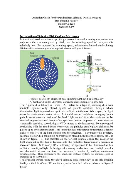
relatively low. To increase the scanning speed, microlens-enhanced dual-spinning<br />
Nipkow <strong>disk</strong> technology can be applied, shown in Figure 1 below:<br />
A<br />
B<br />
Figure 1 Microlens-enhanced dual-spinning Nipkow <strong>disk</strong> technology<br />
A: Nipkow <strong>disk</strong>; B: Microlens-enhanced dual-spinning Nipkow <strong>disk</strong><br />
The Nipkow <strong>disk</strong> (shown in figure 1-A) refers to a type of scanning <strong>disk</strong> with<br />
multiple, symmetrically placed spirals of pinhole apertures through which<br />
illumination light is passed and split into multiple 'minibeams'. When spun, the light<br />
scans the specimen in a raster pattern. As the <strong>disk</strong> rotates, each beam emerging from a<br />
pinhole scans across a portion of the field. Light emitted from the specimen can be<br />
detected to generate a real image of the specimen that can be projected onto a detector<br />
– normally sensitive, cooled, digital CCD camera or the human eye. To ensure good<br />
confocality with this multi-beam technology, the pinholes on a Nipkow <strong>disk</strong> must be<br />
placed up to 10 diameters apart. This limits the light throughput of traditional Nipkow<br />
<strong>disk</strong>s to only 1% of the light shining onto the specimen. To overcome this problem,<br />
second collector <strong>disk</strong> containing microlenses is placed in front of the Nipkow <strong>disk</strong>, as<br />
shown in figure 1-B. The microlenses-one for each pinhole-ensure that most of the<br />
light illuminating the <strong>disk</strong> is focused onto the pinholes. Transmission efficiency is<br />
increased from 1% to nearly 70% , allowing the specimen to be illuminated with a<br />
sufficient quantity of light. In this type of scanning mechanism, since multiple pinholes<br />
are illuminated at any one time, the specimen is excited by multiple mini-beams<br />
simultaneously. Thus compared to the traditional confocal system, the scanning speed is<br />
increased up to 1000 times.<br />
The available system using the above spinning <strong>disk</strong> technology in our Bio-imaging<br />
facility is the UltraView ERS confocal system from PerkinElmer, shown in Figure 2<br />
below:
A<br />
B<br />
Figure 2 UltrView ERS system and demo image<br />
A: UltraVIEW ERS confocal system; B: Sample image by spinning-<strong>disk</strong> confocal
Starting-up procedure<br />
Figure 3 Power buttons for UltrView ERS system<br />
A HAMAMATSU Camera Control Unit: ON<br />
B Xcite 120 Fluorescence Illumination Unit: ON (wait for 5 minutes for best<br />
performance)<br />
C NanScan Z Control Unit: ON<br />
D Nikon Microscope Power Unit: ON<br />
E Incubator Temperature Control Unit: ON<br />
F UltraView ProScan II Unit: ON<br />
Caution: A-F controls are all wired to a power strip on the shelf.<br />
G UltraView ProSync Unit: ON (the power button is on the back side of the unit)<br />
H Laser Control Unit: ON<br />
I Argon Laser Power Unit: power button ON, rotate the key to the right<br />
J Kryptoon Laser Power Unit: power button ON, rotate the key to the right<br />
Shutdown procedure<br />
I & J: rotate the key from right to the top, wait until the cooling systems stop, then<br />
turn off the power button.<br />
A-H: turn off the power button.
<strong>Spinning</strong> Disk Microscope Operation<br />
Control switches<br />
Functions for the control switches are described below:<br />
Figure 4 Control switches for UltrView ERS system<br />
A: Work Mode Switch: switching the system between different work modes<br />
Position 5: for laser scanning mode<br />
Position 1: for eyepiece observation<br />
B: Fine focus adjustment<br />
C: Coarse focus adjustment<br />
D: Locking ring: Do not adjust these two rings.<br />
Objectives<br />
Currently we have the following three objectives available:<br />
(1) 20X objective with NA= 0.75<br />
(2) 60X oil objective with NA= 1.49<br />
(3) 100X oil objective with NA= 1.4<br />
Filter wheel<br />
The filter wheel has the following four positions:<br />
(1) Position 1: for laser scanning<br />
(2) Position 2: for green channel illumination<br />
(3) Position 3: for red channel illumination<br />
(4) Position 4: for UV channel illumination
Volocity Software Operations<br />
(1) Start the Volocity software by double-click the following icon on the desktop:<br />
(2) After double-click the Volocity icon, the following window appears:<br />
(3) Click the icon in the Region A to create a new library for a new experiment, assign<br />
the new library (which will include all your experimental datasets) located in your<br />
own preferred folder:
(4) Next click the icon in Region B to open the Video Preview window:<br />
(5) Video Preview window is activated shown below:
(6) Control icons on the video preview window:<br />
C: Channel selections: right-click each channel icon you will see the corresponding<br />
probe<br />
D: Exposure time: longer exposure time will increase the signal intensity<br />
E: Bin number: merge neighbouring pixels<br />
F: Auto-contrast: auto-adjust the image contrast<br />
G: Gain: signal amplification<br />
H: Offset: background control<br />
I: Objective: objective lens selection<br />
J: Work mode: the system has two work mode (fast sequential & emission<br />
discrimination)<br />
K: Laser shutter control: control the shutter for the laser beam illumination<br />
L: Laser selection: control the different laser source<br />
M: Dichroic mirror selection: dichroic mirror selections for best performance<br />
N: Bright-field light control shutter: control the shutter for the bright-field light<br />
source<br />
O: Emission filter: emission filter control on the signal receiving side<br />
P: X-Y coordinates: the absolute X-Y positions of the stage center<br />
Q: Laser intensity control: control the excitation power for specific laser source<br />
R: Focus control: control the focal point along Z direction<br />
S: Photo-kinetic control: not used in regular acquisition procedure<br />
T: Single frame acquisition: acquire a single frame image<br />
U: Multiple- image acquisition: acquire image sequences or multi-channel image
Caution: the correct settings for the specific channel is shown in the following<br />
table<br />
Channel settings for the UltraView spinning disc confocal system<br />
Channel No. 1 2 3 4 5 6 7 8 9<br />
Dye description GFP RFP DAPI FITC Rhodamine<br />
/TxRd<br />
Cy5 CFP YFP Bright<br />
field<br />
Excitation 488 558 359 495 595 650 435 514 N/A<br />
Wavelength(nm)<br />
Emission 509 583 461 519 613 670 475 527 N/A<br />
Wavelength(nm)<br />
Exposure Time<br />
Adjustable<br />
Objective<br />
20x/60x/100x based on application<br />
Discrimination F.S.* F.S. E.D.** E.D. E.D. E.D. F.S. F.S. N/A<br />
Mode<br />
Laser(nm) 488 561 405 488 561 640 440 514 N/A<br />
Dichroic 405/488/561/640<br />
Emission N/A N/A 3 2 3 4 N/A N/A N/A<br />
Wheel<br />
position # &<br />
Wavelength(nm)<br />
485/705 527 455/615 485/705<br />
F.S.: Fast Sequential Mode<br />
E.D.: Emission Discrimination Mode