Hydrosphere UK Ltd Complete Products & Services Catalogue
Hydrosphere UK Ltd Complete Products & Services Catalogue
Hydrosphere UK Ltd Complete Products & Services Catalogue

You also want an ePaper? Increase the reach of your titles
YUMPU automatically turns print PDFs into web optimized ePapers that Google loves.
Condenser<br />
Night Filter<br />
Colour and Neutral Density Filters<br />
Colour Filters<br />
A PEL Sector Light uses colour to convey<br />
information to the mariner about his<br />
angular position relative to the light. The<br />
process of “colouring” a beam involves<br />
fi ltering out many colours and only<br />
allowing the desired colour to pass.<br />
If the fi lter does not block off enough<br />
undesired colours (wavelengths), there<br />
can be problems with the light appearing<br />
to change colour in fog. If the selection of<br />
wavelengths that is passed is too narrow,<br />
the light will not be intense enough.<br />
In Vega’s experience, the optimum<br />
transmission in coloured fi lters is<br />
about 25%. Vega uses SCHOTT optical<br />
glass for fi lters – OG 590 for red (27%<br />
transmission), and BG23 for blue-green<br />
(24% transmission). BG23 transmits<br />
almost no red or purple light.<br />
Neutral Density Filter in White Sector<br />
In a sector light having red, white and<br />
green sectors, the central white sector<br />
is about 4 times more intense than the<br />
colour sectors.<br />
When there is little or no background<br />
lighting, it is recommended that a 50%<br />
neutral-density fi lter is used for white.<br />
Although this makes the white sector<br />
twice the intensity of the coloured, the<br />
eye perceives the same intensities in all<br />
three sectors. The 50% White Filter will<br />
reduce the intensity but not change<br />
the colour.<br />
With a moderate or high level of<br />
background lighting at night, a clear fi lter<br />
glass is used in the white sector. Because<br />
background lighting at night is mostly<br />
white in colour, this gives comparable<br />
conspicuity within all three sectors.<br />
Night Filters<br />
When a sector light is used for both<br />
day and night operation, the intensity<br />
for night viewing must be reduced to<br />
between 1% and 20% of the daylight<br />
intensity for equivalent conspicuity. This<br />
Coloured Filter<br />
Projection Lens<br />
is more than can be achieved by voltage<br />
reduction at the lamp alone, without<br />
having the fi lament turn orange, and<br />
without interrupting the halogen cycle<br />
on tungsten-halogen lamps.<br />
At night in the PEL-6 Sector Light, a<br />
neutral-density Night Filter is automatically<br />
inserted into the beam to achieve this<br />
reduction. Night Filters can be made<br />
to any transmission value down to 5%.<br />
Voltage reduction at the lamp can also<br />
be used to reduce intensity down to 20%<br />
of peak output. These two reduction<br />
methods are multiplied together to<br />
calculate the resulting intensity as a<br />
percentage of peak intensity (eg 5% x<br />
20% = 1%).<br />
Anti-Refl ection Coatings<br />
Anti-refl ection coatings increase light<br />
transmission through a lens or fi lter.<br />
PEL Sector Lights typically have 10<br />
optical surfaces, so this becomes a useful<br />
improvement. All PEL-6 Lights have<br />
anti-refl ection coatings on all surfaces<br />
except those exposed to the lamp and<br />
the exterior. These coatings are easily<br />
damaged by cleaning, and when damaged<br />
are worse than no coating at all. Coatings<br />
are only applied to PEL-3 lights where<br />
extra performance is required.<br />
Masking of Stray Light<br />
At least 0.5% of light is scattered by the<br />
last lens surface (more if it is not clean),<br />
and becomes stray light. This can be<br />
signifi cant, especially in PEL-6 Lights of<br />
5° subtense or less. An observer could<br />
think he is inside the beam when he is<br />
not. PEL-3 lights of small subtense are<br />
masked with a barrel extension. This is<br />
not practical with the larger apertures of<br />
PEL-6 lights. Panels can be placed some<br />
distance out in front of the light (like horse<br />
blinkers).<br />
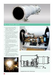
Lamps Used in PEL Sector Lights<br />
Figure 4<br />
M-Series Lamps<br />
PEL Sector Lights use an optical<br />
condenser system to capture light from<br />
the lamp. The condenser system picks<br />
up light from within two opposing 120°<br />
cones. Lamps which emit light mostly<br />
in two directions show signifi cantly<br />
greater effi ciency in this type of optic.<br />
The use of lamps with fl at fi laments (eg.<br />
M-series) produces 41% more intensity<br />
than standard marine lamps with vertical<br />
fi laments. Notwithstanding the above,<br />
PEL-3 lights are fi tted with standard<br />
marine lamps with prefocus candelabra<br />
bases if the required size of lamp is not<br />
available in the M-series.<br />
The PEL Sector Light is limited by the<br />
physical size of the lamp fi lament.<br />
Compact fi laments are preferred,<br />
because the larger the fi lament the larger<br />
the rest of the optic must be to capture<br />
and use the available light. This is why<br />
fi tting a larger lamp than the 250 Watt<br />
M36 lamp will not necessarily increase<br />
intensity, especially if the extra output has<br />
been achieved by enlarging the fi lament.<br />
A larger optical system would also be<br />
required, and the resultant Sector Light<br />
would be much more expensive.<br />
Flashing Constraints with M-Series Lamps<br />
M-series lamps are ideal for achieving<br />
high energy effi ciencies in a PEL Sector<br />
Light. However, the compact, low-voltage<br />
fi lament has some operational constraints<br />
which must be addressed. The fi laments<br />
have very low resistance when cold,<br />
and very high in-rush currents are<br />
experienced every time the lamp is<br />
turned on. The current can be well over<br />
15 times the steady state current (over<br />
150 Amps for M-28 and M-36 lamps).<br />
Lampchangers and fl ashers must be<br />
designed to carry this current. The<br />
CALC-2001 controller limits inrush<br />
current to less than 100 Amps.<br />
M-series lamps require time to warm<br />
up and cool down, as they exhibit<br />
considerable thermal inertia due to the<br />
mass of metal in the fi lament. This limits<br />
the minimum on and off-times to:<br />
M32 12V, 50 Watts 1.0 sec<br />
M28 12V, 100 Watts 1.5 sec<br />
M36 24V, 250 Watts 2.0 sec<br />
Intensity/Time graph of M36 lamp with ISO 4s (2 sec ON,<br />
2 sec OFF) flash character imposed<br />
Figure 5<br />
4