Hydrosphere UK Ltd Complete Products & Services Catalogue
Hydrosphere UK Ltd Complete Products & Services Catalogue
Hydrosphere UK Ltd Complete Products & Services Catalogue

Create successful ePaper yourself
Turn your PDF publications into a flip-book with our unique Google optimized e-Paper software.
for sectored navigation lights. If more than<br />
three sectors are required, the Oscillating<br />
Boundary option should be used, rather<br />
than additional colours.<br />
Projected beam without<br />
filter assembly in place<br />
Cross-section of<br />
Projected beam<br />
Facts about Boundary Resolution<br />
As the mariner traverses from one sector<br />
to an adjacent one, the colour change<br />
must be abrupt. A vague boundary may<br />
not give useful information, because it<br />
requires a subjective assessment<br />
of colour saturation. The PEL Sector Light,<br />
with its very sharp boundaries, gives<br />
precise “digital” information rather than<br />
a more vague “analogue” type. Where a<br />
“proportional” form of signal is required,<br />
the Oscillating Boundary system does this<br />
by having the signal alternate between<br />
two colours on a 3-second cycle.<br />
Modern optical systems as used in the<br />
PEL Sector Light are so precise that there<br />
is no signifi cant zone of uncertainty at<br />
all. A complete colour change will occur<br />
typically within one minute of arc – a<br />
lateral distance of only 2.7 metres at a<br />
distance of 5NM.<br />
Moving towards a PEL Sector Light at<br />
night, with the bridge in darkness, it not<br />
unusual to have the bridge back wall<br />
illuminated in two different colours and<br />
the sudden change in colour at the<br />
boundary clearly displayed by a vertical<br />
line up the bulkhead.<br />
How Sectors are Created<br />
Shadow Method<br />
A coloured sector can be generated<br />
by placing a piece of coloured glass or<br />
acrylic against the lantern house glazing,<br />
or against the beacon itself. This casts a<br />
coloured “shadow” out over the water.<br />
See Figure 3.<br />
The shadow method is adequate if sharp<br />
sector boundaries are not required. A<br />
signifi cant “zone of uncertainty” appears<br />
between adjacent sectors. Within this<br />
transition zone (which may be 1-2° wide)<br />
the beacon will show ambiguous colour,<br />
and intensity may also vary. The sector<br />
boundary moves if the lamp fi lament is<br />
moved (even very slightly), as it might<br />
when a lamp is replaced. Filament<br />
position always varies between lamps.<br />
This method of creating sectors is not<br />
suitable for indicating a precise direction.<br />
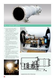
Projection Method<br />
PEL Sector Lights use a “projection”<br />
method. This works the same way as a<br />
slide or movie projector, but focused at<br />
infi nity. Vertical strips of coloured fi lter<br />
glass, optically ground and highly<br />
Lamp<br />
Red Filter<br />
polished on their edges to fi t closely<br />
together, are used as the “slide” or<br />
“fi lm” to divide the beam into its<br />
different sectors.<br />
The condenser system collects light<br />
radiating from the lamp and spreads it<br />
uniformly across the coloured fi lter.<br />
Lamps which project light mostly in two<br />
opposing directions give better energy<br />
effi ciency in this type of optic (eg “M”<br />
series halogen lamps).<br />
Total<br />
Subtense<br />
Plan View<br />
Chart Entry<br />
Red Shadow (sector)<br />
An image of the exit surface of the fi lter<br />
(right side on diagram) is projected out<br />
to infi nity. Sector boundaries may appear<br />
blurred within the fi rst few hundred metres<br />
as they are out of focus, but will be very<br />
sharp at working distances. Small changes<br />
in lamp fi lament position may cause minor<br />
changes in intensity within the beam,<br />
Zone of Uncertainly<br />
Vertical<br />
Divergence<br />
Subtense<br />
but will have absolutely no effect on the<br />
boundary positions, which are fi xed by the<br />
projection lens system.<br />
The projection lens (sometimes called<br />
objective lens) and fi lter assembly together<br />
determine the total subtense of the PEL<br />
Light. Different objective systems are<br />
used to obtain all the different subtenses<br />
with optimal effi ciency. Generally, smaller<br />
subtenses require larger projection lenses<br />
and longer barrel lengths.<br />
The optical system in PEL Sector Lights<br />
produces very uniform intensity (before<br />
colouring) in all viewing directions.<br />
Boundary resolution and accuracy of<br />
sector boundary placement can both<br />
be as precise as 1 minute of arc.<br />
See Figure 4.<br />
R<br />
W<br />
G<br />
Figure 1<br />
Figure 2<br />
Figure 3<br />
3