Hydrosphere UK Ltd Complete Products & Services Catalogue
Hydrosphere UK Ltd Complete Products & Services Catalogue
Hydrosphere UK Ltd Complete Products & Services Catalogue

You also want an ePaper? Increase the reach of your titles
YUMPU automatically turns print PDFs into web optimized ePapers that Google loves.
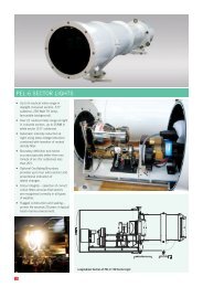
OSCILLATING BOUNDARY AND SECTOR ANGLES<br />
Oscillating Boundary<br />
Defi nition<br />
Oscillating Boundary is a factory-fi tted<br />
option for any PEL Light. It provides up<br />
to four additional sectors without any<br />
new colours, and proportional indication<br />
of lateral movement within a sector. The<br />
Oscillating Boundary is best appreciated<br />
using a moving model, as shown on the<br />
Vega website, www.vega.co.nz.<br />
Benefi t<br />
The Oscillating Boundary provides early<br />
warning of deviation from the centre<br />
line, and enables extremely precise<br />
navigation. It is ideal for use by large<br />
ships moving in very narrow channels,<br />
especially when there is adverse wind<br />
or tide.<br />
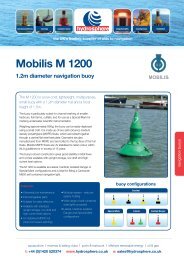
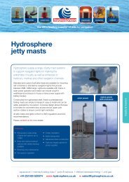
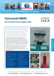
Maximum Range Required<br />
Distance to Control Point<br />
Largest<br />
Vessel at<br />
Edge of<br />
Channel<br />
Section Through Control Point<br />
Fl R 3s R Alt R/W W Alt G/W G Fl G 3s<br />
Fl G<br />
G<br />
Alt G/ W<br />
W<br />
Alt R/W<br />
R<br />
Fl R<br />
Figure 6<br />
Signal Format<br />
In the oscillating sector the colour<br />
oscillates between the colours of the<br />
sectors on either side. A complete<br />
oscillation occurs every 3 seconds. The<br />
oscillation is seen by an observer within<br />
the sector as an abrupt change<br />
of colour from red to white (for example),<br />
and back to red. The period of time that<br />
one colour is ivisible (relative to the other<br />
colour) is a measure of the closeness of<br />
the fi xed sector of that colour.<br />
The signal is easily and intuitively<br />
grasped by the mariner. A longer red<br />
fl ash and a shorter white fl ash means<br />
that the mariner is closer to the red<br />
sector, and vice versa. Judging the<br />
proportion of time in which each<br />
colour is displayed is quite<br />
straightforward, and the cycle<br />
repeats every three seconds.<br />
The Oscillating Boundary signal does not<br />
change when viewed through binoculars.<br />
It is a time-based digital signal, rather<br />
than one based on relative lateral<br />
displacement.<br />
Flash Character<br />
It is recommended that a PEL Light with<br />
Oscillating Boundary does not have any<br />
fl ashing character imposed on the lamp,<br />
as this combination could be confusing.<br />
A character with a longer on-period<br />
(for example, 8.0 seconds) could be<br />
tolerated, followed by a brief off-period.<br />
This character would help to confi rm the<br />
light identity to a mariner when holding<br />
position in the white sector, especially if<br />
there was signifi cant background lighting<br />
at night.<br />
Maximum Size of Individual Sectors<br />
There is no restriction on size of fi xed<br />
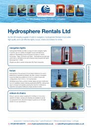
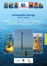
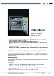
To calculate sector angles:<br />
A1° = atan(W1/C)<br />
A2° = atan(W2/C)<br />
A° = A 2° - A1°<br />
A1°<br />
A2°<br />
Distance to control point = C<br />
sectors. The maximum width of an<br />
oscillating sector is limited to 20% of total<br />
subtense, and all oscillating sectors must<br />
be the same size.<br />
A°<br />
By placing the outer fl ashing sectors<br />
outside the total subtense of the light,<br />
they are masked out and not seen. Partial<br />
masking is also possible. See Figure 6.<br />
Determining Individual Sector Angles<br />
Largest Vessel at Control Point<br />
The control point is any convenient point<br />
at which the required width of each sector<br />
is established. This could be a restricted<br />
part of the approach, such as the heads at<br />
the harbour entrance or the entrance to a<br />
narrow channel.<br />
At the control point consider the largest<br />
vessel on the extreme edge of its safe<br />
manoeuvring area. Take the centre-line<br />
of the vessel at this point, and set the<br />
outer edge of the oscillating sector. Refer<br />
to example above. When the mariner<br />
encounters the fi xed red or green sectors<br />
(while standing at the centre of the vessel)<br />
he has reached the limit of his safe<br />
manoeuvring space.<br />
Narrow Centre Sector<br />
At the centre, allow the smallest practical<br />
white sector. Half the width of the largest<br />
W1<br />
distance to centre = W 2<br />
centre line of channel<br />
Figure 7<br />
vessel when at the control point is a useful<br />
starting value. This format gives a very<br />
early indication of any deviation from the<br />
central sector, as the mariner sees a fl ash<br />
of red or green depending on whether the<br />
vessel has moved left or right.<br />
Flashing Sectors<br />
With the Oscillating Boundary system<br />
there is the option to use part or all of<br />
the two outside fl ashing sectors.<br />
Converting Lateral Distances to Angles<br />
Use the arc-tangent function to convert<br />
measurements of distance from the<br />
centreline and distance to control point<br />
into angles in degrees. See Figure 7.<br />
Sector Light Alignment<br />
When selecting individual sector angles,<br />
it is a good idea to place one sector edge<br />
across a defi ned location, preferably one<br />
that can be reached by land. An observer<br />
at this location can easily check the<br />
alignment of the entire light from time<br />
to time.<br />
Specifying Sector Angles<br />
When specifying individual sector angles,<br />
always list by colour and size (in degrees),<br />
working from left to right as viewed from<br />
the position of the vessel, looking towards<br />
the light.<br />
13