PEL 3 datasheet - Hydrosphere UK Ltd.
PEL 3 datasheet - Hydrosphere UK Ltd.
PEL 3 datasheet - Hydrosphere UK Ltd.

Create successful ePaper yourself
Turn your PDF publications into a flip-book with our unique Google optimized e-Paper software.
guides the way<br />
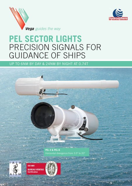
<strong>PEL</strong> SECTOR LIGHTS<br />
PRECISION SIGNALS FOR<br />
GUIDANCE OF SHIPS<br />
UP TO 6NM BY DAY & 24NM BY NIGHT AT 0.74T<br />
<strong>PEL</strong>-3 & <strong>PEL</strong>-6<br />
Horizontal divergence from 3.5° to 20°
ABOUT SECTOR LIGHTS<br />
<strong>PEL</strong> Sector Lights display a different<br />
colour when viewed from different angles<br />
at sea. Very sharp colour boundaries – a<br />
complete colour change typically occurs<br />
within 1 minute of arc. With optional<br />
oscillating boundary, the signal alternates<br />
between two colours in proportion to the<br />
distance across the sector. <strong>PEL</strong> Sector<br />
Lights indicate the precise vessel position<br />
in confi ned waterways. They are used<br />
in situations where extreme accuracy is<br />
required, or where only a single station is<br />
possible. Each light is custom-confi gured<br />
for its site. Range up to 6NM by day<br />
from <strong>PEL</strong>-6.<br />
Defi nition of a Sector Light<br />
A Sector Light is a single light which<br />
shows a different colour when viewed<br />
from different directions. The colour of<br />
the light provides directional information<br />
to the mariner. The letters “<strong>PEL</strong>” stand<br />
for Physics and Engineering Laboratory<br />
of the New Zealand government research<br />
facility where the fi rst <strong>PEL</strong> light was<br />
designed.<br />
Benefi ts of <strong>PEL</strong> Sector Lights include<br />
ease of location, energy effi ciency, and<br />
cost savings. <strong>PEL</strong> Lights only require a<br />
single station for direction-indicating,<br />
saving on the costs of a rear light,<br />
including site access, power supply and<br />
structures.<br />
<strong>PEL</strong> Sector Lights have been applied to<br />
a wide range of uses. Although mainly<br />
used as single-station leads, they have<br />
been used to mark anchorages, turning<br />
basins, fi shing zones, hazardous reefs,<br />
national boundaries and prohibited<br />
areas.<br />
Sector Light Vocabulary<br />
Total Subtense<br />
Total subtense is the total projected angle<br />
in the horizontal plane. The basic light<br />
beam is circular in cross-section, and is<br />
masked down to a rectangle as shown<br />
fi gure 1 & 2.<br />
Vertical Divergence<br />
Vertical divergence is the total projected<br />
angle in the vertical plane. Stated vertical<br />
divergence applies across the full width<br />
of the beam of the <strong>PEL</strong> Light. This is<br />
always less than the horizontal subtense<br />
of the light due to the way the circular<br />
beam is masked.<br />
Boundary Resolution<br />
On the boundary between a white and a<br />
coloured sector (eg red) there is a small<br />
transition angle within which the colour is<br />
neither completely white nor completely<br />
red. Boundary resolution is the smallest<br />
angle over which a complete colour<br />
change occurs.<br />
Sector Accuracy<br />
Due to manufacturing tolerances on<br />
lenses, fi lter glasses and lens-mounting<br />
systems, the actual location of a sector<br />
boundary may be displaced a small<br />
amount from the intended place.<br />
Accuracy is the maximum angle between<br />
intended and actual location.<br />
Intensity and Range<br />
Intensity is the amount of light energy<br />
emitted from a light in a given direction,<br />
and is measured in candela. Increased<br />
intensity gives increased viewing range,<br />
but typically, range also depends on<br />
atmospheric transmissivity and level of<br />
background lighting.<br />
Oscillating Boundary<br />
An optional accessory to the <strong>PEL</strong><br />
Sector Light which generates up to four<br />
additional sectors without using additional<br />
colours (only red, white and green). Refer<br />
to Oscillating Boundary section.<br />
Facts about Colour Integrity<br />
White and red are both satisfactory<br />
colours for use in navigation beacons.<br />
If a third colour is required, care must<br />
be taken to ensure that the chosen<br />
colour and fi lter material will maintain<br />
a consistent appearance in adverse<br />
weather conditions.<br />
Yellow is not a suitable colour because<br />
it cannot be distinguished from white,<br />
especially with fi lament lamps used at<br />
low voltage.<br />
Fog can be a problem with coloured<br />
beacons, because fog scatters light of<br />
shorter wavelength (blue) more than<br />
of longer wavelength (red). When a<br />
yellow, green or blue beacon is viewed<br />
through fog, if there is a signifi cant red<br />
component in the light, then red may<br />
be the main colour that is seen. This<br />
phenomenon has caused accidents at<br />
sea. Purple-coloured beacons should<br />
also be avoided.<br />
Despite the above, green remains the<br />
most suitable third colour. There are<br />
many blue and blue-green fi lter glasses<br />
and plastics which also freely transmit<br />
some red light. Great care is required in<br />
the selection of fi lter glass for blue-green<br />
sectors to ensure that no red light is<br />
transmitted. The use of colours other than<br />
red, white and green is not recommended<br />
2
for sectored navigation lights. If more than<br />
three sectors are required, the Oscillating<br />
Boundary option should be used, rather<br />
than additional colours.<br />
Projected beam without<br />
filter assembly in place<br />
Cross-section of<br />
Projected beam<br />
Facts about Boundary Resolution<br />
As the mariner traverses from one sector<br />
to an adjacent one, the colour change<br />
must be abrupt. A vague boundary may<br />
not give useful information, because it<br />
requires a subjective assessment<br />
of colour saturation. The <strong>PEL</strong> Sector Light,<br />
with its very sharp boundaries, gives<br />
precise “digital” information rather than<br />
a more vague “analogue” type. Where a<br />
“proportional” form of signal is required,<br />
the Oscillating Boundary system does this<br />
by having the signal alternate between<br />
two colours on a 3-second cycle.<br />
Modern optical systems as used in the<br />
<strong>PEL</strong> Sector Light are so precise that there<br />
is no signifi cant zone of uncertainty at<br />
all. A complete colour change will occur<br />
typically within one minute of arc – a<br />
lateral distance of only 2.7 metres at a<br />
distance of 5NM.<br />
Moving towards a <strong>PEL</strong> Sector Light at<br />
night, with the bridge in darkness, it not<br />
unusual to have the bridge back wall<br />
illuminated in two different colours and<br />
the sudden change in colour at the<br />
boundary clearly displayed by a vertical<br />
line up the bulkhead.<br />
How Sectors are Created<br />
Shadow Method<br />
A coloured sector can be generated<br />
by placing a piece of coloured glass or<br />
acrylic against the lantern house glazing,<br />
or against the beacon itself. This casts a<br />
coloured “shadow” out over the water.<br />
See Figure 3.<br />
The shadow method is adequate if sharp<br />
sector boundaries are not required. A<br />
signifi cant “zone of uncertainty” appears<br />
between adjacent sectors. Within this<br />
transition zone (which may be 1-2° wide)<br />
the beacon will show ambiguous colour,<br />
and intensity may also vary. The sector<br />
boundary moves if the lamp fi lament is<br />
moved (even very slightly), as it might<br />
when a lamp is replaced. Filament<br />
position always varies between lamps.<br />
This method of creating sectors is not<br />
suitable for indicating a precise direction.<br />
Projection Method<br />
<strong>PEL</strong> Sector Lights use a “projection”<br />
method. This works the same way as a<br />
slide or movie projector, but focused at<br />
infi nity. Vertical strips of coloured fi lter<br />
glass, optically ground and highly<br />
Lamp<br />
Red Filter<br />
polished on their edges to fi t closely<br />
together, are used as the “slide” or<br />
“fi lm” to divide the beam into its<br />
different sectors.<br />
The condenser system collects light<br />
radiating from the lamp and spreads it<br />
uniformly across the coloured fi lter.<br />
Lamps which project light mostly in two<br />
opposing directions give better energy<br />
effi ciency in this type of optic (eg “M”<br />
series halogen lamps).<br />
Total<br />
Subtense<br />
Plan View<br />
Chart Entry<br />
Red Shadow (sector)<br />
An image of the exit surface of the fi lter<br />
(right side on diagram) is projected out<br />
to infi nity. Sector boundaries may appear<br />
blurred within the fi rst few hundred metres<br />
as they are out of focus, but will be very<br />
sharp at working distances. Small changes<br />
in lamp fi lament position may cause minor<br />
changes in intensity within the beam,<br />
Zone of Uncertainly<br />
Vertical<br />
Divergence<br />
Subtense<br />
but will have absolutely no effect on the<br />
boundary positions, which are fi xed by the<br />
projection lens system.<br />
The projection lens (sometimes called<br />
objective lens) and fi lter assembly together<br />
determine the total subtense of the <strong>PEL</strong><br />
Light. Different objective systems are<br />
used to obtain all the different subtenses<br />
with optimal effi ciency. Generally, smaller<br />
subtenses require larger projection lenses<br />
and longer barrel lengths.<br />
The optical system in <strong>PEL</strong> Sector Lights<br />
produces very uniform intensity (before<br />
colouring) in all viewing directions.<br />
Boundary resolution and accuracy of<br />
sector boundary placement can both<br />
be as precise as 1 minute of arc.<br />
See Figure 4.<br />
R<br />
W<br />
G<br />
Figure 1<br />
Figure 2<br />
Figure 3<br />
3
Condenser<br />
Night Filter<br />
Colour and Neutral Density Filters<br />
Colour Filters<br />
A <strong>PEL</strong> Sector Light uses colour to convey<br />
information to the mariner about his<br />
angular position relative to the light. The<br />
process of “colouring” a beam involves<br />
fi ltering out many colours and only<br />
allowing the desired colour to pass.<br />
If the fi lter does not block off enough<br />
undesired colours (wavelengths), there<br />
can be problems with the light appearing<br />
to change colour in fog. If the selection of<br />
wavelengths that is passed is too narrow,<br />
the light will not be intense enough.<br />
In Vega’s experience, the optimum<br />
transmission in coloured fi lters is<br />
about 25%. Vega uses SCHOTT optical<br />
glass for fi lters – OG 590 for red (27%<br />
transmission), and BG23 for blue-green<br />
(24% transmission). BG23 transmits<br />
almost no red or purple light.<br />
Neutral Density Filter in White Sector<br />
In a sector light having red, white and<br />
green sectors, the central white sector<br />
is about 4 times more intense than the<br />
colour sectors.<br />
When there is little or no background<br />
lighting, it is recommended that a 50%<br />
neutral-density fi lter is used for white.<br />
Although this makes the white sector<br />
twice the intensity of the coloured, the<br />
eye perceives the same intensities in all<br />
three sectors. The 50% White Filter will<br />
reduce the intensity but not change<br />
the colour.<br />
With a moderate or high level of<br />
background lighting at night, a clear fi lter<br />
glass is used in the white sector. Because<br />
background lighting at night is mostly<br />
white in colour, this gives comparable<br />
conspicuity within all three sectors.<br />
Night Filters<br />
When a sector light is used for both<br />
day and night operation, the intensity<br />
for night viewing must be reduced to<br />
between 1% and 20% of the daylight<br />
intensity for equivalent conspicuity. This<br />
Coloured Filter<br />
Projection Lens<br />
is more than can be achieved by voltage<br />
reduction at the lamp alone, without<br />
having the fi lament turn orange, and<br />
without interrupting the halogen cycle<br />
on tungsten-halogen lamps.<br />
At night in the <strong>PEL</strong>-6 Sector Light, a<br />
neutral-density Night Filter is automatically<br />
inserted into the beam to achieve this<br />
reduction. Night Filters can be made<br />
to any transmission value down to 5%.<br />
Voltage reduction at the lamp can also<br />
be used to reduce intensity down to 20%<br />
of peak output. These two reduction<br />
methods are multiplied together to<br />
calculate the resulting intensity as a<br />
percentage of peak intensity (eg 5% x<br />
20% = 1%).<br />
Anti-Refl ection Coatings<br />
Anti-refl ection coatings increase light<br />
transmission through a lens or fi lter.<br />
<strong>PEL</strong> Sector Lights typically have 10<br />
optical surfaces, so this becomes a useful<br />
improvement. All <strong>PEL</strong>-6 Lights have<br />
anti-refl ection coatings on all surfaces<br />
except those exposed to the lamp and<br />
the exterior. These coatings are easily<br />
damaged by cleaning, and when damaged<br />
are worse than no coating at all. Coatings<br />
are only applied to <strong>PEL</strong>-3 lights where<br />
extra performance is required.<br />
Masking of Stray Light<br />
At least 0.5% of light is scattered by the<br />
last lens surface (more if it is not clean),<br />
and becomes stray light. This can be<br />
signifi cant, especially in <strong>PEL</strong>-6 Lights of<br />
5° subtense or less. An observer could<br />
think he is inside the beam when he is<br />
not. <strong>PEL</strong>-3 lights of small subtense are<br />
masked with a barrel extension. This is<br />
not practical with the larger apertures of<br />
<strong>PEL</strong>-6 lights. Panels can be placed some<br />
distance out in front of the light (like horse<br />
blinkers).<br />
Lamps Used in <strong>PEL</strong> Sector Lights<br />
Figure 4<br />
M-Series Lamps<br />
<strong>PEL</strong> Sector Lights use an optical<br />
condenser system to capture light from<br />
the lamp. The condenser system picks<br />
up light from within two opposing 120°<br />
cones. Lamps which emit light mostly<br />
in two directions show signifi cantly<br />
greater effi ciency in this type of optic.<br />
The use of lamps with fl at fi laments (eg.<br />
M-series) produces 41% more intensity<br />
than standard marine lamps with vertical<br />
fi laments. Notwithstanding the above,<br />
<strong>PEL</strong>-3 lights are fi tted with standard<br />
marine lamps with prefocus candelabra<br />
bases if the required size of lamp is not<br />
available in the M-series.<br />
The <strong>PEL</strong> Sector Light is limited by the<br />
physical size of the lamp fi lament.<br />
Compact fi laments are preferred,<br />
because the larger the fi lament the larger<br />
the rest of the optic must be to capture<br />
and use the available light. This is why<br />
fi tting a larger lamp than the 250 Watt<br />
M36 lamp will not necessarily increase<br />
intensity, especially if the extra output has<br />
been achieved by enlarging the fi lament.<br />
A larger optical system would also be<br />
required, and the resultant Sector Light<br />
would be much more expensive.<br />
Flashing Constraints with M-Series Lamps<br />
M-series lamps are ideal for achieving<br />
high energy effi ciencies in a <strong>PEL</strong> Sector<br />
Light. However, the compact, low-voltage<br />
fi lament has some operational constraints<br />
which must be addressed. The fi laments<br />
have very low resistance when cold,<br />
and very high in-rush currents are<br />
experienced every time the lamp is<br />
turned on. The current can be well over<br />
15 times the steady state current (over<br />
150 Amps for M-28 and M-36 lamps).<br />
Lampchangers and fl ashers must be<br />
designed to carry this current. The<br />
CALC-2001 controller limits inrush<br />
current to less than 100 Amps.<br />
M-series lamps require time to warm<br />
up and cool down, as they exhibit<br />
considerable thermal inertia due to the<br />
mass of metal in the fi lament. This limits<br />
the minimum on and off-times to:<br />
M32 12V, 50 Watts 1.0 sec<br />
M28 12V, 100 Watts 1.5 sec<br />
M36 24V, 250 Watts 2.0 sec<br />
Intensity/Time graph of M36 lamp with ISO 4s (2 sec ON,<br />
2 sec OFF) flash character imposed<br />
Figure 5<br />
4
The effective intensity of a lamp fl ashed<br />
by switching on and off, with an onperiod<br />
of T secs duration, is proportional<br />
to T/(T+0.2). If the range is barely<br />
adequate then long on-times should be<br />
used. See Figure 5.<br />
Lamp Life and Voltage Control<br />
Virtually all <strong>PEL</strong> Sector Lights are<br />
powered by batteries, and this is the<br />
recommended approach. Batteries can<br />
be charged by mains charger, or by solar<br />
panels. The voltage from the batteries<br />
will frequently exceed the rated voltage<br />
of the lamp. Applying such a voltage<br />
signifi cantly reduces lamp life from their<br />
rated 2000 hours.<br />
To prevent inadvertent lamp life<br />
reduction the CALC controller used on<br />
all <strong>PEL</strong> Sector Lights applies pulse-width<br />
modulation to lamp power, reducing the<br />
DC-rms power as necessary to ensure<br />
that the rated power of the lamp is never<br />
exceeded. When pulse-width modulation<br />
is active, the voltage measured at the<br />
lamp by a multi-meter will not be an<br />
accurate representation of the rms<br />
voltage. Meters measuring AC-rms<br />
voltage are not effective – an oscilloscope<br />
must be used to obtain an accurate<br />
reading.<br />
Power Supplies<br />
Voltage Spikes<br />
Mains-powered battery chargers and<br />
other mains-driven power supplies must<br />
be free of voltage spikes. Power supplies<br />
with high internal inductance present a<br />
problem when used to drive low-voltage<br />
lighted aids to navigation.<br />
When a lamp fails at the end of its life,<br />
this will often occur during the current<br />
inrush at startup. The sudden drop in<br />
current from a very high value (150<br />
Amps) to zero can induce large transient<br />
voltages (100-200 Volts) if there is any<br />
inductance in the supply circuit. This<br />
will damage controllers which are only<br />
designed to withstand voltages of<br />
the order of 40 Volts.<br />
Inductive Elements<br />
Older power supplies were built with<br />
inductive elements (chokes) which<br />
worked in conjunction with a capacitive<br />
element to smooth the pulsed DC after<br />
rectifi cation. These inductors store<br />
a large amount of energy in normal<br />
operation, and this energy generates the<br />
damaging voltage spikes.<br />
Battery Protection<br />
When initially installed and connected<br />
to a continuous battery charger, new<br />
batteries may have suffi cient capacity<br />
to absorb spikes, and they do not reach<br />
the Sector Light electronics. However,<br />
as batteries deteriorate over time this<br />
capability reduces, and spike damage to<br />
electronic equipment may start occurring.<br />
SMR Power Supplies Only<br />
Power supplies with high internal<br />
inductance are not suitable for use with<br />
neither <strong>PEL</strong> Sector Lights nor other lowvoltage<br />
lights. Switch-mode regulated<br />
battery chargers of good quality are<br />
recommended. Use the Vega VPR-39<br />
weatherproof switch-mode power supply<br />
if in doubt.<br />
Achieving Maximum Service Life<br />
Life Expectancy<br />
Many <strong>PEL</strong> Sector Lights around the<br />
world have been in service for more than<br />
20 years. Vega routinely refurbishes<br />
<strong>PEL</strong> Sector Lights back to new condition,<br />
which includes repolishing and recoating<br />
the optics, upgrading the electronics and<br />
repainting the exterior, for a fraction of<br />
the cost of a new light.<br />
Protection Against Moisture Ingress<br />
Users can enhance the life and<br />
performance of <strong>PEL</strong> Sector Lights by<br />
preventing ingress of moisture. This<br />
occurs whenever the light is opened for<br />
servicing, as it is otherwise completely<br />
sealed (each light holds 4 psi without<br />
leakage as a factory test).<br />
For longevity each light is best installed<br />
within a shelter, with just the barrel<br />
protruding. This reduces temperature<br />
changes imposed on the light from<br />
outside, and reduces bird fouling.<br />
Packs of properly-dried silica gel should<br />
always be left in the lampchanger area of<br />
each light between servicing, to absorb<br />
moisture introduced with each opening.<br />
Internal inspections should be no more<br />
frequent than six monthly, with twelve<br />
months being the normal.<br />
Routine Servicing<br />
Ensure lights are properly resealed after<br />
closing. Always inspect the condition<br />
and cleanliness of the O-ring seal and<br />
mating surface.<br />
Choosing a Sector Light<br />
Choice of Different Sizes<br />
Each marine port and harbour is unique,<br />
so a fl exible system is required. The<br />
<strong>PEL</strong> Light offers a range of subtenses<br />
and intensities to accommodate the<br />
constraints of each site. <strong>PEL</strong> Sector<br />
Lights make very effi cient use of solar<br />
power on remote sites.<br />
When a signal is required both day and<br />
night it is convenient if a single light can<br />
perform both functions. A light needs to<br />
be up to 5,000 times more intense<br />
during the day compared to night. The<br />
<strong>PEL</strong>-6 Sector Light has been designed for<br />
day & night operation.<br />
Two Models: <strong>PEL</strong>-3 and <strong>PEL</strong>-6<br />
There are two models of <strong>PEL</strong> Sector<br />
Light, <strong>PEL</strong>-3 and the <strong>PEL</strong>-6. Both<br />
are available in a range of standard<br />
subtenses, from 3.5° to 20°. The <strong>PEL</strong>-3<br />
is designed for night use, and uses lamps<br />
up to 100 Watts. Small prefocused lamps<br />
down to 10 Watts can be used where less<br />
intensity is acceptable and limited energy<br />
is available. The <strong>PEL</strong>-6 has much larger<br />
optics and is designed to meet the need<br />
for a day & night sector light. It carries<br />
a 250 Watt lamp, and automatically<br />
reduces intensity at night by two methods<br />
used together: night fi lter insertion and<br />
lamp voltage reduction.<br />
Balancing Intensity Against Subtense<br />
For a given lamp size in a <strong>PEL</strong> Sector<br />
Light, the wider the beam the less the<br />
intensity. An increase in horizontal<br />
subtense also gives an increase in<br />
vertical divergence, because the optics<br />
are circular (except with anamorphic<br />
models). Doubling the subtense will<br />
drop intensity to one-quarter (following<br />
the inverse-square law). The narrowest<br />
subtense that will meet the requirement<br />
should be used. If greater subtense or<br />
intensity is required, consider multiple<br />
lights or special anamorphic versions<br />
which spread light horizontally but<br />
keep the same vertical divergence.<br />
Choosing Individual Sector Angles<br />
For a leading line, one approach is to<br />
select a control point, like a harbour<br />
entrance. Consider the widest vessel<br />
passing the control point, and decide the<br />
width (in metres) of each sector at that<br />
point. The central white sector should<br />
be quite narrow – it is not marking the<br />
edges, but an acceptable deviation from<br />
the centre line before a colour change<br />
is seen. Use the tangent function to<br />
calculate individual sector angles.<br />
Night Intensity Reduction (Day & Night<br />
Lights) With all <strong>PEL</strong> Sector Lights,<br />
there are 6 options for lamp voltage at<br />
night, given that voltage during the day<br />
is 100%:<br />
5
5. Oscillating Boundary Option: Yes or No<br />
This option is used in critical applications<br />
where early warning of deviation from a<br />
central line is required. On solar-powered<br />
sites it may be less attractive because<br />
long lamp on-periods are required for its<br />
effective operation. Refer to Oscillating<br />
Boundary.<br />
6. Determine Individual Sector Angles<br />
Each sector light is individually<br />
confi gured for its end use. For most<br />
applications red, white and green colours<br />
are chosen. The sector sizes are always<br />
specifi ed reading from left to right when<br />
looking towards the light from on board<br />
the vessel.<br />
7. Check Vertical Divergence<br />
Sketch a vertical profi le through the light<br />
and viewing area. Check that mariners<br />
on highest and lowest vessels at closest<br />
and most distant points all fall within the<br />
vertical divergence of the light.<br />
Dixon Cove (16°20’N, 86°29’W) – Roatan is one of the Honduras Bay Islands in the Caribbean Sea.<br />
A <strong>PEL</strong>-3-3.5D, solar powered with on-demand switching via VHF marine radio has been deployed in<br />
the Dixon Cove Harbour of Roatan Island.<br />
Night Step <strong>PEL</strong>-3 Volts <strong>PEL</strong>-6 Volts Average Current Night Intensity<br />
1 12.0 24.0 100% 100%<br />
2 11.0 22.0 88% 75%<br />
3 10.3 20.5 80% 60%<br />
4 9.0 18.0 65% 40%<br />
5 7.2 14.4 47% 20%<br />
6 6.0 12.0 36% 10%<br />
<strong>PEL</strong>-6 lights have the night intensity<br />
further reduced by insertion of a Night<br />
Filter with a transmission between 5%<br />
and 50%. Where lamp voltage reduction<br />
and a night fi lter are used together, the<br />
fi nal transmission is the product of the<br />
two values.<br />
Example:<br />
• 60% of peak intensity from lamp<br />
voltage reduction<br />
• 5% transmission through night filter<br />
(when inserted)<br />
• Night intensity = 60% x 5% = 3%<br />
of day intensity<br />
Specifi cation Sequence<br />
1. Night Only or Day & Night<br />
The fi rst decision is whether a night-only<br />
signal is required, or a day and night<br />
signal. Generally, use a <strong>PEL</strong>-3 for night<br />
only, or a <strong>PEL</strong>-6 for day & night. For very<br />
short distances a <strong>PEL</strong>-3 can be used in<br />
daylight, but night dimming is only by<br />
voltage reduction.<br />
2. Determine Required Intensity<br />
This depends on the range required<br />
and the conditions under which viewing<br />
occurs (transmissivity of atmosphere,<br />
level of background lighting). Use IALA<br />
Recommendations for guidance, or<br />
contact Vega for assistance.<br />
3. Choose Total Subtense<br />
There is a tradeoff between subtense and<br />
intensity – the greater the subtense the<br />
less the intensity (for a given lamp). Refer<br />
to <strong>PEL</strong>-3 and <strong>PEL</strong>-6 tables for intensities.<br />
4. Choose Lamp Size<br />
For the <strong>PEL</strong>-3 the maximum size lamp<br />
is 100 Watts. The M28 100W lamp gives<br />
best performance, but smaller lamps are<br />
adequate for lower intensities. Refer to<br />
table of lamp performance for <strong>PEL</strong>-3<br />
Lights. For the <strong>PEL</strong>-6 the M36 250 Watt<br />
lamp (24 Volts) is standard, but smaller<br />
lamps can be accommodated.<br />
8. Specify Flash Character<br />
Each <strong>PEL</strong> Sector Light uses a CALC-2001<br />
controller, which has 256 fl ash codes.<br />
Certain lamps have minimum on and<br />
off-times. For Oscillating Boundary (OB)<br />
use a fi xed character, or one with at least<br />
8 seconds on-time to allow at least two<br />
full OB cycles.<br />
9. Specify Night Intensity Reduction<br />
(if applicable)<br />
When the <strong>PEL</strong> Light is used day and<br />
night, intensity reduction is required at<br />
night. Night intensity is a percentage of<br />
day intensity. Lamp voltage reduction<br />
value can be adjusted in the fi eld, but<br />
changing the Night Filter transmission<br />
requires a new fi lter.<br />
10. Reduced Intensity in White Sector:<br />
Yes or No<br />
Intensity in the white sector can be<br />
reduced to 50% using a ND fi lter to<br />
match the apparent intensities in the<br />
coloured sectors.<br />
11. Anti-Refl ection Coatings (<strong>PEL</strong>-3)<br />
These give up to 35% extra intensity in<br />
critical applications.<br />
12. Connections to Other Devices<br />
Synchronisation to other lights,<br />
monitoring interfaces, remote on-off<br />
or intensity control.<br />
6
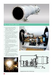
<strong>PEL</strong>-3 SECTOR LIGHTS<br />
• Invented in New Zealand by Norman<br />
Rumsey, acclaimed international<br />
optical designer and astronomer.<br />
• Modern optical design techniques<br />
and minimisation of optical<br />
aberrations achieve very sharp sector<br />
boundaries.<br />
• Up to 19NM range at night (coloured<br />
sectors, 3.5° subtense, 100 Watt<br />
TH lamp, anti-reflection coatings).<br />
• Great configuration flexibility – each<br />
light is customised to suit the exact<br />
requirements of the end user.<br />
• Wide choice of subtenses, individual<br />
sector angles, lamp types and sizes,<br />
flash characters and operating<br />
modes.<br />
• Designed for use in rugged marine<br />
environments without further<br />
protection. Sealed enclosure, built<br />
from gunmetal (marine-grade<br />
bronze) and stainless steel.<br />
• Energy efficient – each optical<br />
system makes best use of energy<br />
available from the lamp.<br />
• Suitable for solar power – operates<br />
from 12VDC. Light can be flashed<br />
to reduce power consumption.<br />
• Uniform intensity from one side of<br />
the beam to the other – intensity<br />
does not reduce due to movement<br />
off axis.<br />
• Delivered fully tested and ready<br />
to operate, complete with Vega<br />
6-position lampchanger and<br />
CALC-2001 controller.<br />
• Long service life – many <strong>PEL</strong>-3<br />
Sector Lights have been in<br />
continuous service for over 20 years.<br />
French Guiana – <strong>PEL</strong>-3<br />
• Can be interfaced to remote switching and monitoring equipment – interfaces<br />
are available. Optical isolation recommended when connecting to other<br />
electrical equipment.<br />
7
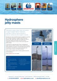
SPECIFICATIONS<br />
DIMENSIONS<br />
Light Source<br />
Lamp Mounting<br />
Primary<br />
Refl ector<br />
Filament lamp,<br />
max 110 Watt<br />
tungsten halogen<br />
Bi-pin (M-series<br />
lamps), or prefocus<br />
candelabra<br />
First-surface spherical,<br />
aluminium coated<br />
Condenser Type Two element<br />
(spherical+aspheric),<br />
120° pickup<br />
Lampchanger Vega VLC-152A<br />
(bi-pin), VLC-150<br />
(pre-focus)<br />
Power Supply 12-16VDC, battery<br />
fl oat (mains or solar)<br />
Anti-Refl ection<br />
Coatings<br />
Non-standard on<br />
<strong>PEL</strong>-3, available as<br />
an option<br />
Flash Characters Fixed +255<br />
characters,<br />
user-selectable<br />
Flasher/Controller CALC-2001<br />
computer-assisted<br />
light controller<br />
Lamp Power<br />
Regulation<br />
Construction<br />
Materials<br />
Exterior fi nish<br />
Pulse-widthmodulation<br />
regulates<br />
power to lamp<br />
Gunmetal, stainless<br />
steel, copper tube<br />
Epoxy primersurfacer,<br />
2-pot<br />
polyurethane gloss<br />
<strong>PEL</strong>-3-3.5D<br />
377<br />
<strong>PEL</strong>-3-5D<br />
<strong>PEL</strong>-3-7D<br />
<strong>PEL</strong>-3-10D<br />
<strong>PEL</strong>-3-15D<br />
255<br />
993<br />
90<br />
1263<br />
1611<br />
1100<br />
2002<br />
153<br />
<strong>PEL</strong>-3-3.5D<br />
Mounting Layout<br />
140<br />
390<br />
140<br />
144<br />
525<br />
45<br />
65<br />
308<br />
370<br />
Scale 1:20<br />
710<br />
<strong>PEL</strong>-3-20D<br />
209<br />
474<br />
789<br />
70<br />
141<br />
124<br />
124<br />
Pivot ±5˚ horizontal<br />
<strong>PEL</strong>-3-5 /10 /15 /20D<br />
Mounting Hole Layout<br />
Rear Can slides<br />
back 390 mm and<br />
hinges down for<br />
servicing access<br />
Longitudinal Section of <strong>PEL</strong>-3 20D Sector Light<br />
8
<strong>PEL</strong>-3 Peak Intensities in White, Red and Green Sectors<br />
<strong>PEL</strong>-3 Total Subtense Colour 3.5° 5.0° 7.0° 10° 15° 20°<br />
M28<br />
12V 100W TH<br />
(Coated Optics)<br />
M28<br />
12V 100W TH<br />
M32<br />
12V 50W TH<br />
NAL 86 100W<br />
PF Halogen<br />
NAL 85 75W<br />
PF Halogen<br />
NAL 84 50W<br />
PF Halogen<br />
NAL 83 35W<br />
PF Halogen<br />
NAL 82 20W<br />
PF Halogen<br />
NAL 81 10W<br />
PF Halogen<br />
W 301,674 147,868 75,489 37,038 16,514 9,330<br />
R 81,452 39,924 20,382 10,000 4,459 2,519<br />
G 72,402 35,488 18,117 8,889 3,963 2,239<br />
W 220,430 108,045 55,159 27,063 12,066 6,817<br />
R 59,516 29,172 14,893 7,307 3,258 1,841<br />
G 52,903 25,931 13,238 6,495 2,896 1,636<br />
W 78,069 38,266 19,536 9,585 4,274 2,415<br />
R 21,079 10,332 5,275 2,588 1,154 652<br />
G 18,737 9,184 4,689 2,300 1,026 580<br />
W 149,819 73,435 37,490 18,393 8,201 4,633<br />
R 40,451 19,827 10,122 4,966 2,214 1,251<br />
G 35,957 17,624 8,998 4,414 1,968 1,112<br />
W 87,937 43,103 22,004 10,796 4,813 2,719<br />
R 23,743 11,638 5,941 2,915 1,300 734<br />
G 21,105 10,345 5,281 2,591 1,155 653<br />
W 65,139 31,928 16,300 7,997 3,565 2,014<br />
R 17,588 8,621 4,401 2,159 963 544<br />
G 15,633 7,663 3,912 1,919 856 483<br />
W 42,340 20,754 10,595 5,198 2,318 1,310<br />
R 11,432 5,604 2,861 1,403 626 354<br />
G 10,162 4,981 2,543 1,248 556 314<br />
W 22,799 11,175 5,705 2,799 1,248 705<br />
R 6,156 3,017 1,540 756 337 190<br />
G 5,472 2,682 1,369 672 300 169<br />
W 9,771 4,789 2,445 1,200 535 302<br />
R 2,638 1,293 660 324 144 82<br />
G 2,345 1,149 587 288 128 73<br />
Vertical Divergence 2.0° 3.0° 3.4° 4.3° 5.0° 5.6°<br />
Boundary Resolution