Fittings & Adapters - Thorburn Flex Inc
Fittings & Adapters - Thorburn Flex Inc
Fittings & Adapters - Thorburn Flex Inc

Create successful ePaper yourself
Turn your PDF publications into a flip-book with our unique Google optimized e-Paper software.
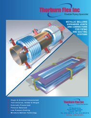
Precision Machined “O” Seal<br />
Hose <strong>Adapters</strong> and Tube Fitting Bodies<br />
INSTALLATION & ASSEMBLY OF THORBURN O-SEAL<br />
To install “O” Seal assemblies:<br />
1. Assemble fitting body or bodies into desired<br />
port(s). (Fig. 1) Install securely using recommended<br />
torques as per Table. Lubricate O-ring.<br />
2. Cut tubing to required length. De-burr and<br />
clean both tube ends and socket of spud to<br />
keep free of grease, rust, etc.<br />
3. Slip spud on tube end. Make sure tube is completely<br />
bottomed in the socket. (Fig. 2)<br />
Note: nut is inserted over tubing before spud<br />
is positioned.<br />
4. Test fit of tube and spud assembly between the<br />
fitting bodies prior to brazing of the spuds<br />
(Fig. 3). If fit does not conform to alignment criteria,<br />
refabricate tube.<br />
5. Conduct brazing of spud to tube in accordance<br />
with MIL-B-7883B specification. Not recommended<br />
that spud be brazed while in contact<br />
with fitting body. Remove excess braze from<br />
outer surface of spud. (Fig. 4)<br />
6. Install brazed tube assembly to fitting bodies by<br />
screwing nuts on finger tight, then tighten nuts<br />
to recommended torques listed in Table.<br />
1. FITTING BODY INSTALLATION 2. TUBE FULLY BOTTOMED<br />
IN SPUD<br />
O-Ring face<br />
of fitting body<br />
Port End<br />
3. TEST FIT OF ASSEMBLY 4.<br />
Sleeve tube<br />
assembly<br />
Fitting body<br />
Section A<br />
Remove all<br />
braze from<br />
spud surface<br />
ASSEMBLY TORQUE TABLE FOR “O” SEAL HOSE ADAPTER<br />
<br />
<br />
<br />
<br />
<br />
<br />
<br />
<br />
<br />
4 7<br />
/16-20 .172 190±10 22±1 220±10 27±1<br />
6 9<br />
/16-18 .264 420±20 48±2 320±15 35±2<br />
8 3<br />
/4-16 .382 720±35 81±4 480±25 54±3<br />
10 7<br />
/8-14 .482 1260±60 142±7 750±35 84±4<br />
12 1 1 /16-12 .609 1680±80 190±9 1050±50 118±5<br />
16 1 5 /16-12 .812 2520±125 284±14 1440±75 160±8<br />
20 1 5 /8-12 1.045 3080±150 345±17 1680±85 190±9<br />
24 1 7 /8-12 1.312 3780±180 425±20 2000±100 220±10<br />
Alignment Criteria<br />
Common industrial is to allow a .060 inch true position tolerance on bent tube brazed<br />
assemblies. With point A fixed, point B can be anywhere within a .60 radius sphere of true<br />
position. This means that some means of adjustment of fitting ends must be provided.<br />
Protect<br />
face<br />
Remove<br />
excess<br />
braze<br />
Another possible method is to use a C tube<br />
configuration. For a 10 inch leg length, a .060<br />
true position tolerance would mean that the<br />
maximum angle of deviation would be approximately<br />
1/3 of a degree or 20 minutes.<br />
Adjustable elbows used with a C brazed<br />
tube assembly allow additional movement.<br />
Adjustable Tees or Elbows<br />
<br />
<br />
<br />
<br />
<br />
<br />
<br />
<br />
A<br />
B<br />
<br />
40