Oceanview Renovation
Oceanview Renovation
Oceanview Renovation

You also want an ePaper? Increase the reach of your titles
YUMPU automatically turns print PDFs into web optimized ePapers that Google loves.
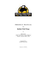
PROJECT MANUAL<br />
for<br />
<strong>Oceanview</strong> <strong>Renovation</strong><br />
Clearwater, Florida<br />
ISSUED FOR CONSTRUCTION<br />
April 26, 2011<br />
Owner: Church of Scientology Religious Trust, 503<br />
Cleveland Street, Clearwater, FL 33755<br />
Civil and Landscape: Kimley Horn and Associates, 2601<br />
Cattlemen Road, Suite 500, Sarasota, FL 34232<br />
Architect: Gensler, 101 Marietta Street NW, Suite 3000,<br />
Atlanta, GA 30303<br />
Structural Engineer: Mohan Engineering, 13630 58 th<br />
Street North, Suite 107, Clearwater, FL 33760<br />
Roofing Consultant: Roof Engineering Associates, 500<br />
County Road One, PO Box 549, Palm Harbor, FL 34684<br />
Elevator Consultant: Lerch Bates, 2300 Glades Road,<br />
Suite 230 W, Glades Twin Plaza West, Boca Raton, FL<br />
33431<br />
Pool Consultant: Gardner Collins, 1268 Rogers Street,<br />
Clearwater, FL 33756<br />
Mechanical, Plumbing and Fire Protection Engineers:<br />
Stewart Engineering Consultants, Inc., 1859 Northgate<br />
Blvd., Sarasota, FL 34234<br />
Electrical Engineer: KBA Engineering, Inc., 201 Flagship<br />
Drive, Suite E, Lutz, FL 33549
Gensler April 26, 2011 <strong>Oceanview</strong> <strong>Renovation</strong><br />
13.7123.000 Issued for Construction Clearwater, Florida<br />
TABLE OF CONTENTS<br />
PROCUREMENT AND CONTRACTING REQUIREMENTS GROUP<br />
DIVISION 00 – PROCUREMENT AND CONTRACTING REQUIREMENTS<br />
INTRODUCTORY INFORMATION<br />
Date Section No. Title<br />
00 01 01 Project Title Page<br />
00 01 10 Table Of Contents<br />
PROCUREMENT REQUIREMENTS<br />
Date Section No. Title<br />
00 21 13 Instructions To Bidders<br />
00 21 16 Instructions To Proposers<br />
00 31 32 Geotechnical Data<br />
00 41 00 Bid Form<br />
00 42 00 Proposal Form<br />
CONTRACTING REQUIREMENTS<br />
Date Section No. Title<br />
00 52 00 Agreement Form<br />
00 61 00 Bonds<br />
00 72 00 General Conditions<br />
00 73 00 Supplementary Conditions<br />
00 91 13 Addenda<br />
TABLE OF CONTENTS 00 01 10 - 1<br />
Copyright 2011 Gensler
Gensler April 26, 2011 <strong>Oceanview</strong> <strong>Renovation</strong><br />
13.7123.000 Issued for Construction Clearwater, Florida<br />
SPECIFICATIONS GROUP<br />
GENERAL REQUIREMENTS SUBGROUP<br />
DIVISION 01 - GENERAL REQUIREMENTS<br />
Date Section No. Title<br />
01 10 00 Summary<br />
01 14 00 Work Restrictions<br />
01 23 00 Alternates<br />
01 25 00 Substitution Procedures<br />
01 25 00.01 Substitution Request Form<br />
01 26 00 Contract Modification Procedures<br />
01 26 00.01 Bulletin Form<br />
01 26 00.02 Change Order Form<br />
01 26 13 Requests for Interpretation (RFIs)<br />
01 26 13.01 Request for Interpretation Form<br />
01 29 00 Payment Procedures<br />
01 31 00 Project Management and Coordination<br />
01 32 00 Construction Progress Documentation<br />
01 33 00 Submittal Procedures<br />
01 33 00.01 Data Transfer Agreement<br />
01 33 10 Coordination Drawings<br />
01 40 00 Quality Requirements<br />
01 42 00 References<br />
01 50 00 Temporary Facilities And Controls<br />
01 60 00 Product Requirements<br />
01 73 00 Execution<br />
01 73 29 Cutting And Patching<br />
01 77 00 Closeout Procedures<br />
01 77 00.01 Closeout Procedure Form<br />
FACILITY CONSTRUCTION SUBGROUP<br />
DIVISION 02 – EXISTING CONDITIONS<br />
Date Section No. Title<br />
02 22 00 Site Preparation, Excavation, and Earthwork for Foundations –<br />
specification as provided by Mohan Engineering<br />
02 41 19 Selective Structure Demolition<br />
TABLE OF CONTENTS 00 01 10 - 2<br />
Copyright 2011 Gensler
Gensler April 26, 2011 <strong>Oceanview</strong> <strong>Renovation</strong><br />
13.7123.000 Issued for Construction Clearwater, Florida<br />
DIVISION 03 – CONCRETE<br />
Date Section No. Title<br />
03 30 00 Cast-In-Place Concrete Foundations – specification as provided by<br />
Mohan Engineering<br />
03 54 16 Hydraulic Cement Underlayment<br />
DIVISION 04 – MASONRY<br />
Date Section No. Title<br />
04 20 00 Unit Masonry – specification as provided by Mohan Engineering<br />
DIVISION 05 – METALS<br />
Date Section No. Title<br />
05 04 00 Hot Dip Galvanizing – specification as provided by Mohan<br />
Engineering<br />
05 12 00 Structural Steel – specification as provided by Mohan Engineering<br />
05 21 00 Steel Joists – specification as provided by Mohan Engineering<br />
05 31 00 Steel Deck – specification as provided by Mohan Engineering<br />
05 40 00 Structural Studs - specification as provided by Mohan Engineering<br />
05 50 00 Metal Fabrications<br />
05 52 13 Pipe and Tube Railings<br />
DIVISION 06 – WOOD, PLASTICS, AND COMPOSITES<br />
Date Section No. Title<br />
06 10 53 Miscellaneous Rough<br />
06 16 00 Sheathing<br />
06 40 23 Interior Architectural Woodwork<br />
DIVISION 07 – THERMAL AND MOISTURE PROTECTION<br />
Date Section No. Title<br />
07 01 50.19 Preparation for Re-Roofing<br />
07 19 00 Water Repellents<br />
07 21 00 Thermal Insulation<br />
07 25 00 Weather Barriers<br />
07 54 19 Polyvinyl-Chloride (PVC) Roofing<br />
07 62 00 Sheet Metal Flashing and Trim<br />
07 71 00 Roof Specialties<br />
07 71 29 Manufactured Roof Expansion Joints<br />
07 72 00 Roof Accessories<br />
07 81 00 Applied Fireproofing<br />
07 84 13 Penetration Firestopping<br />
07 84 46 Fire-Resistive Joint Systems<br />
07 92 00 Joint Sealants<br />
07 95 00 Expansion Control<br />
TABLE OF CONTENTS 00 01 10 - 3<br />
Copyright 2011 Gensler
Gensler April 26, 2011 <strong>Oceanview</strong> <strong>Renovation</strong><br />
13.7123.000 Issued for Construction Clearwater, Florida<br />
DIVISION 08 – OPENINGS<br />
Date Section No. Title<br />
08 11 13 Hollow Metal Doors and Frames<br />
08 12 16 Aluminum Doors and Frames<br />
08 14 16 Flush Wood Doors<br />
08 31 00 Access Doors And Frames<br />
08 32 13 Sliding Aluminum-Framed Glass<br />
08 41 13 Aluminum-Framed Entrances and Storefronts<br />
08 51 13 Aluminum Windows<br />
08 71 00 Door Hardware<br />
08 80 00 Glazing<br />
DIVISION 09 – FINISHES<br />
Date Section No. Title<br />
09 24 00 Portland Cement Plastering<br />
09 29 00 Gypsum Board<br />
09 30 00 Tiling<br />
09 30 33 Stone Tiling<br />
09 51 13 Acoustical Panel Ceilings<br />
09 61 23 Concrete Flooring Treatment<br />
09 64 00 Wood Flooring<br />
09 65 13 Resilient Base and Accessories<br />
09 65 19 Resilient Tile Flooring<br />
09 91 13 Exterior Painting<br />
09 91 23 Interior Painting<br />
09 96 53 Elastomeric Coatings<br />
DIVISION 10 – SPECIALTIES<br />
Date Section No. Title<br />
10 28 00 Toilet, Bath, and Laundry Accessories<br />
10 44 00 Fire-Protection Specialties<br />
DIVISION 11 – EQUIPMENT<br />
Date Section No. Title<br />
11 31 00 Pantry and Residential Appliances<br />
DIVISION 12 – FURNISHINGS<br />
Date Section No. Title<br />
12 36 40 Stone Countertops<br />
TABLE OF CONTENTS 00 01 10 - 4<br />
Copyright 2011 Gensler
Gensler April 26, 2011 <strong>Oceanview</strong> <strong>Renovation</strong><br />
13.7123.000 Issued for Construction Clearwater, Florida<br />
DIVISION 13 - SPECIAL CONSTRUCTION<br />
Date Section No. Title<br />
NOT APPLICABLE for THIS PROJECT<br />
DIVISION 14 – CONVEYING EQUIPMENT<br />
Date Section No. Title<br />
DOCUMENTATION TO BE PROVIDED BY CONSULTANT<br />
DIVISIONS 15 through 19 – Reserved<br />
Date Section No. Title<br />
NOT APPLICABLE for THIS PROJECT<br />
TABLE OF CONTENTS 00 01 10 - 5<br />
Copyright 2011 Gensler
Gensler April 26, 2011 <strong>Oceanview</strong> <strong>Renovation</strong><br />
13.7123.000 Issued for Construction Clearwater, Florida<br />
FACILITY SERVICES SUBGROUP<br />
DIVISION 20 – Reserved<br />
DIVISION 21 – FIRE SUPPRESSION - REFER TO FIRE SUPPRESSION SHEET<br />
SPECIFICATIONS<br />
DIVISION 22 – PLUMBING<br />
Date Section No. Title<br />
22 05 00 Common Work Results for Plumbing<br />
22 05 16 Expansion Fittings and Loops for Plumbing Piping<br />
22 05 19 Meters and Gages for Plumbing Piping<br />
22 05 23 General Duty Valves for Plumbing Piping<br />
22 05 29 Hangers and Supports for Plumbing Piping and Equipment<br />
22 05 42 Plumbing Pumps<br />
22 05 53 Identification for Plumbing Piping and Equipment<br />
22 07 00 Plumbing Insulation<br />
22 11 13 Facility Water Distribution Piping<br />
22 11 16 Domestic Water Piping<br />
22 11 19 Domestic Water Piping Specialties<br />
22 11 25 Natural Gas Systems<br />
22 13 16 Sanitary Waste and Vent Piping<br />
22 14 13 Facility Storm Drainage Piping<br />
22 33 00 Electric Domestic Water Heaters<br />
22 40 00 Plumbing Fixtures<br />
DIVISION 23 – HEATING, VENTILATING, AND AIR CONDITIONING<br />
Date Section No. Title<br />
23 05 00 Basic Mechanical Requirements<br />
23 05 12 Mechanical Related Work<br />
23 05 13 Electrical Provisions of Mechanical Work<br />
23 05 16 Expansion Compensation<br />
23 05 19 Meters and Gages<br />
23 05 23 Valves<br />
23 05 29 Hangers and Supports for HVAC Piping and Equipment<br />
23 05 48 Vibration Control<br />
23 05 53 Mechanical Identification<br />
23 05 93 Testing, Adjusting and Balancing<br />
23 07 00 Mechanical Insulation<br />
23 09 15 Variable Frequency Drives<br />
23 21 13 Hydronic Piping Systems<br />
23 21 16 Piping Specialties<br />
23 21 23 HVAC Pumps<br />
23 31 12 Phenolic Foam Ductwork<br />
23 31 13 Metal Ductwork<br />
23 33 00 Ductwork Accessories<br />
23 37 00 Air Oulets and Inlets<br />
TABLE OF CONTENTS 00 01 10 - 6<br />
Copyright 2011 Gensler
Gensler April 26, 2011 <strong>Oceanview</strong> <strong>Renovation</strong><br />
13.7123.000 Issued for Construction Clearwater, Florida<br />
23 64 22 Air Cooled Scroll Chillers (70-Tons or Greater)<br />
23 82 15 Air Handling Units (Chilled Water)<br />
DIVISION 24 – Reserved<br />
DIVISION 25 – INTEGRATED AUTOMATION<br />
Date Section No. Title<br />
25 09 23 Direct Digital Control System for HVAC<br />
DIVISION 26 – ELECTRICAL<br />
Date Section No. Title<br />
26 01 00 Basic Electrical Requirements<br />
26 05 19 Low Voltage Electrical Power Conductors and Cables<br />
26 05 20 Electrical Connections for Equipment<br />
26 05 26 Grounds and Bonding for Electrical Systems<br />
26 05 29 Hangers and Supports for Electrical Systems<br />
26 05 33 Raceways and Boxes for Electrical Systems<br />
26 05 53 Identification for Electrical Systems<br />
26 24 16 Panelboards<br />
26 27 26 Wiring Devices<br />
26 28 16 Enclosed Switches and Circuit Breakers<br />
26 29 13 Motor Starters<br />
26 32 13 Engine Generators<br />
26 36 00 Transfer Switches<br />
26 41 13 Lighting Protection for Structures<br />
26 43 13 Transient Voltage Suppression for Low Voltage Electrical Power<br />
Circuits<br />
26 51 00 Interior Lighting<br />
DIVISION 27 – COMMUNICATIONS<br />
Date Section No. Title<br />
27 11 00 Telephone and Data Systems<br />
TABLE OF CONTENTS 00 01 10 - 7<br />
Copyright 2011 Gensler
Gensler April 26, 2011 <strong>Oceanview</strong> <strong>Renovation</strong><br />
13.7123.000 Issued for Construction Clearwater, Florida<br />
DIVISION 28 – ELECTRONIC SAFETY AND SECURITY<br />
Date Section No. Title<br />
28 31 12 Fire Alarm Systems<br />
DIVISION 29 – Reserved<br />
SITE AND INFRASTRUCTURE SUBGROUP – REFER TO CIVIL AND LANDSCAPE SHEET<br />
SPECIFICATIONS<br />
DIVISION 30 – Reserved<br />
DIVISION 31 – EARTHWORK<br />
DIVISION 32 – EXTERIOR IMPROVEMENTS<br />
DIVISION 33 – UTILITIES<br />
DIVISION 34 – TRANSPORTATION<br />
DIVISION 35 – WATERWAY AND MARINE CONSTRUCTION<br />
DIVISIONS 36 through 39 – Reserved<br />
END OF TABLE OF CONTENTS<br />
TABLE OF CONTENTS 00 01 10 - 8<br />
Copyright 2011 Gensler
Gensler April 26, 2011 <strong>Oceanview</strong> <strong>Renovation</strong><br />
13.7123.000 Issued for Construction Clearwater, Florida<br />
SECTION 00 52 00 – AGREEMENT FORM<br />
PART 1 - GENERAL<br />
1.1 The Agreement Form will be the Standard Form of Agreement between the Owner and<br />
Contractor as published by the American Institute of Architect (AIA), Document [A101-1987]<br />
[A101-1997] [A111-1987] [A111-1997].<br />
1.2 The Agreement Form will be in the form as attached to this Section for information.<br />
PART 2 - PRODUCTS (Not Used)<br />
PART 3 - EXECUTION (Not Used)<br />
END OF SECTION 00 52 00<br />
AGREEMENT FORM 00 52 00 - 1<br />
Copyright 2011 Gensler
Gensler April 26, 2011 <strong>Oceanview</strong> <strong>Renovation</strong><br />
13.7123.000 Issued for Construction Clearwater, Florida<br />
SECTION 00 61 00 – BONDS<br />
1.1 Security Bonds: Submit a Performance Bond and a Payment Bond, AIA Document A312 that<br />
is included in these Specifications by reference as if written out in full. Copies of this document<br />
may be examined at the office of the Architect or purchased from the American Institute of<br />
Architects.<br />
END OF SECTION 00 61 00<br />
BONDS 00 61 00 - 1<br />
Copyright 2011 Gensler
Gensler April 26, 2011 <strong>Oceanview</strong> <strong>Renovation</strong><br />
13.7123.000 Issued for Construction Clearwater, Florida<br />
SECTION 00 72 00 – GENERAL CONDITIONS<br />
PART 1 - GENERAL<br />
1.1 General Conditions of the Contract for Construction, AIA Document A201, 2007 Edition,<br />
hereinafter referred to as General Conditions, are hereby made a part of this Specification.<br />
1.2 The Contractor is hereby specifically directed, as a condition of the Contract, to acquaint<br />
himself with the Articles contained therein, and to notify and apprise all Subcontractors and any<br />
other parties to the Contract of, and bind them to, its conditions.<br />
1.3 No contractual adjustments shall be due as a result of failure on the part of the Contractor,<br />
Subcontractors or other parties to the Contract to fully acquaint themselves with the General<br />
Conditions.<br />
1.4 The General Conditions of the Contract may be amended by Supplementary Conditions.<br />
1.5 The provisions of the General and Supplementary Conditions when included and Division 01,<br />
General Requirements, apply to the Work specified in each Section of the Specifications.<br />
1.6 Where conflicts occur concerning the Architect's duties and responsibilities between the<br />
General Conditions and the Agreement between the Owner and Architect, the Agreement shall<br />
take precedence.<br />
1.7 If not otherwise included in the Owner Contractor Agreement or specifically included in the<br />
bidding documents, the Contractor shall obtain the Owner’s insurance requirements prior to<br />
submitting a bid.<br />
PART 2 - PRODUCTS (Not Used)<br />
PART 3 - EXECUTION (Not Used)<br />
END OF SECTION 00 72 00<br />
GENERAL CONDITIONS 00 72 00 - 1<br />
Copyright 2011 Gensler
Gensler April 26, 2011 <strong>Oceanview</strong> <strong>Renovation</strong><br />
13.7123.000 Issued for Construction Clearwater, Florida<br />
SECTION 00 73 00 – SUPPLEMENTARY CONDITIONS<br />
AIA Document A201-2007, in its entirety, shall constitute the General Conditions of the Contract for<br />
Construction (the “General Conditions”). These Supplementary Conditions of the Contract for Construction<br />
(“Supplementary Conditions”) are attached to and made a part of the Contract Documents and are<br />
intended to modify and/or supplement the General Conditions. Capitalized terms used herein but not defined<br />
herein shall have the same meanings as in the General Conditions.<br />
ARTICLE 1<br />
GENERAL PROVISIONS<br />
1. Subparagraph 1.1.9 – Other Definitions: Add the following new Subparagraph 1.1.9 as follows:<br />
1.1.9 OTHER DEFINITIONS<br />
.1 “As required” shall mean as required by regulatory bodies, by referenced standards,<br />
by existing conditions, by generally accepted construction practice, or by<br />
the Contract Documents.<br />
.2 “By Others” refers to work that is not part of the Contract.<br />
.3 “By Owner” refers to work that will be performed by Owner or Owner’s agents<br />
at Owner’s cost.<br />
.4 “Equal”, “accepted equal”, and “approved equal” shall mean as accepted, in writing,<br />
by Architect as being of equivalent quality, utility, and appearance.<br />
.5 “Furnish” means supply only, do not install.<br />
.6 “Install” means install only, do not furnish.<br />
.7 “Provide” means furnish and install.<br />
2. Subparagraph 1.2.2: Add the following new wording to the end of Subparagraph 1.2.2:<br />
Documents prepared by entities other than Architect or its consultants may be included with<br />
documents prepared by Architect or its consultants for convenience in pricing, bidding, permit<br />
application, construction or other purposes. The inclusion of such documents not prepared<br />
by the Architect or its consultants within the Contract Documents shall not imply that<br />
Architect has reviewed, approved or is responsible for the accuracy or completeness of such<br />
documents.<br />
3. Paragraph 1.5 – Ownership and Use of Drawings, Specifications and Other Instruments of Service:<br />
Add the following new subparagraph 1.5.3:<br />
§1.5.3 In the event of any unauthorized use, reuse, transfer or modification of the Drawings,<br />
Specifications or other documents by Contractor, any lower tier contractor or material<br />
supplier, or other person or entity under Contractor's direct or indirect employ, Contractor<br />
agrees to indemnify, defend and hold Owner, Architect, their officers, directors, shareholders,<br />
employees, agents, and consultants harmless from and against any and all claims, liabilities,<br />
SUPPLEMENTARY CONDITIONS 00 73 00 - 1<br />
Copyright 2011 Gensler
Gensler April 26, 2011 <strong>Oceanview</strong> <strong>Renovation</strong><br />
13.7123.000 Issued for Construction Clearwater, Florida<br />
suits, demands, losses, damages, costs and expenses, including, but not limited to, reasonable<br />
attorneys' fees and all legal expenses and fees incurred through appeal, and all interest<br />
thereon, accruing to or resulting from any and all persons, firms, or any other legal entities on<br />
account of any damages or losses to property or persons, including, but not limited to, injuries<br />
or death or economic losses arising out of such unauthorized use, reuse, transfer or<br />
modification, except where Architect is found to be solely liable as between the parties hereto<br />
as well as between any other persons, firms or other legal entities for such damages or losses<br />
by a court or forum of competent jurisdiction.<br />
4. Subparagraph 1.6 – Transmission of Data in Digital Form: Add the following sentence at the end of<br />
Subparagraph 1.6:<br />
Any electronic transfer of Drawings, Specifications or other documents (“Data”) by the Architect<br />
to the Contractor shall be subject to the terms of the Architect’s standard Data Transfer<br />
Agreement, which shall be executed by the Contractor.<br />
ARTICLE 3<br />
CONTRACTOR<br />
5. Subparagraph 3.2.1: Add the following new sentence to the end of Subparagraph 3.2.1:<br />
Additionally, Contractor acknowledges and agrees that the information contained in the Contract<br />
Documents is adequate and sufficient for completion of the Work.<br />
6. Subparagraph 3.2.4: Revise the second sentence of Subparagraph 3.2.4 to read as follows:<br />
If the Contractor fails to perform the obligations of Sections 3.2.2 or 3.2.3, or reasonably<br />
should have recognized any errors, inconsistencies, omissions or nonconformity and failed to<br />
do so, the Contractor shall pay such costs and damages to the Owner as would have been<br />
avoided if the Contractor had performed such obligations.<br />
7. Subparagraph 3.2.5: Add the following new Subparagraph 3.2.5:<br />
§3.2.5 In the event of conflicts or discrepancies among the Contract Documents, the following<br />
order of precedence shall govern: (1) Amendments and revisions (such as change orders),<br />
with those of later date taking precedence over those of earlier date; (2) the Agreement; (3)<br />
the Supplementary Conditions; (4) the General Conditions; (5) Drawings and Specifications.<br />
Drawings shall govern Specifications for quantity and location, and Specifications shall govern<br />
Drawings for quality and performance. In case of an inconsistency between Drawings<br />
and Specifications or within either Document not clarified by addendum, the better quality or<br />
greater quantity of Work shall be provided in accordance with the Architect’s interpretation.<br />
8. Subparagraph 3.4.2: Add the following new text to the end of Subparagraph 3.4.2:<br />
Any requests for substitution shall be made in a timely manner and in full compliance with all<br />
Contract requirements. By making a request for substitution, Contractor: (1) represents that<br />
the Contractor has investigated the proposed substitute product and determined that it is equal<br />
to or superior in all respects to that specified; (2) represents that the Contractor will provide<br />
the same warranty for the substitution that the Contractor would for that specified; (3) certifies<br />
that the cost data presented is complete and includes all related costs under this Contract<br />
except for the Architect’s redesign costs, and waives all claims for additional costs related to<br />
the substitution which subsequently become apparent; and (4) will coordinate the installation<br />
SUPPLEMENTARY CONDITIONS 00 73 00 - 2<br />
Copyright 2011 Gensler
Gensler April 26, 2011 <strong>Oceanview</strong> <strong>Renovation</strong><br />
13.7123.000 Issued for Construction Clearwater, Florida<br />
of the accepted substitute, making such changes as may be required for the Work to be complete<br />
in all respects.<br />
9. Subparagraph 3.7.3: Modify Subparagraph 3.7.3 as follows:<br />
§3.7.3 If the Contractor performs Work knowing it to be which Contractor knows or should<br />
know is contrary to applicable laws, statutes, ordinances, codes, rules and regulations, or lawful<br />
orders of public authorities, the Contractor shall assume appropriate responsibility for<br />
such Work and shall bear the costs attributable to correction.<br />
10. Subparagraph 3.9.1: Add the following new text to the end of Subparagraph 3.9.1:<br />
The superintendent shall be approved by Owner and shall not be replaced without Owner's<br />
prior approval. The superintendent shall be familiar with the job site, the Contract Documents,<br />
and all applicable rules, regulations and requirements of all authorities having jurisdiction<br />
over the Work or the site.<br />
11. Subparagraph 3.10.1: Add the following to the end of Subparagraph 3.10.1:<br />
Such schedule shall be a computer generated critical path method (CPM) schedule showing at<br />
a minimum: (1) the early and late start time for each major construction activity; (2) all "critical<br />
path" activities and their duration; (3) late order dates for all long lead time materials and<br />
equipment; and (4) critical Owner decision dates.<br />
12. Subparagraph 3.10.4: Add the following new Subparagraph 3.10.4:<br />
§3.10.4 Failure of Contractor to submit or keep current the construction schedule and submittals<br />
schedule as required by the conditions of the Work, shall be grounds for withholding<br />
of payments due Contractor by Owner, until such schedules are provided.<br />
13. Subparagraph 3.12.6: Add the following text to the end of Subparagraph 3.12.6:<br />
Incomplete, uncoordinated or incorrect Shop Drawings and other submittals shall be returned<br />
to Contractor who shall be held responsible for all time delays and extra costs of review or<br />
handling by Architect or Owner, because of such submittals being incomplete, uncoordinated<br />
or incorrect.<br />
14. Subparagraph 3.12.7: Modify Subparagraph 3.12.7 as follows:<br />
3.12.7 The Contractor shall perform no portion of the Work for which the Contract Documents<br />
require submittal and review of Shop Drawings, Product Data, Samples or similar<br />
submittals until the respective submittal has been approved reviewed and returned by the<br />
Architect.<br />
15. Subparagraph 3.12.8: Modify Subparagraph 3.12.8 as follows:<br />
3.12.8 The Work shall be in accordance with approved Architect-reviewed submittals except<br />
that the Contractor shall not be relieved of responsibility for deviations from requirements<br />
of the Contract Documents by the Architect’s approval review of Shop Drawings,<br />
Product Data, Samples or similar submittals unless the Contractor has specifically informed<br />
the Architect in writing of such deviation at the time of submittal and (1) the Architect has<br />
SUPPLEMENTARY CONDITIONS 00 73 00 - 3<br />
Copyright 2011 Gensler
Gensler April 26, 2011 <strong>Oceanview</strong> <strong>Renovation</strong><br />
13.7123.000 Issued for Construction Clearwater, Florida<br />
given written approval to the specific deviation as a minor change in the Work, or (2) a<br />
Change Order or Construction Change Directive has been issued authorizing the deviation.<br />
The Contractor shall not be relieved of responsibility for errors or omissions in Shop Drawings,<br />
Product Data, Samples or similar submittals by the Architect’s approval review thereof.<br />
If more than one submittal review stamp (Architect’s and one or more of its consultants’<br />
stamp) appears on a submittal, the most stringent action and notations thereon shall apply.<br />
Signature on a submittal review stamp by the Architect or a consultant does not imply that it<br />
has reviewed Work not within its professional discipline or scope of services.<br />
16. Subparagraph 3.12.10: Modify the second to last sentence of Subparagraph 3.12.10 as follows:<br />
Pursuant to this Subparagraph 3.12.10, the Architect will review, approve or take other<br />
appropriate action on submittals only for the limited purpose of checking for conformance<br />
with information given and the visual and aesthetic design concept expressed in the Contract<br />
Documents.<br />
17. Subparagraph 3.18.1: Revise Subparagraph 3.18.1 as follows:<br />
§3.18.1 To the fullest extent permitted by law the Contractor shall indemnify, defend and<br />
hold harmless the Owner, Architect, Architect's consultants, and agents and employees of any<br />
of them from and against claims, liabilities, suits, demands, damages, losses, costs and expenses,<br />
including, but not limited to reasonable attorneys’ fees, and all legal expenses, and<br />
fees incurred through appeal, and all interest thereon, arising out of or resulting from the performance<br />
of the Work, provided that such claim, damage, loss or expenses is attributable to<br />
bodily injury, sickness, disease or death or to injury to or destruction of tangible property<br />
(other than the Work itself), but only to the extent caused by the negligent acts or omissions<br />
of the Contractor, a Subcontractor, anyone directly or indirectly employed by them or anyone<br />
for whose acts they may be liable, regardless of whether or not such claim, damage, loss or<br />
expense is caused in part by a party indemnified hereunder. Such obligation shall not be construed<br />
to negate, abridge, or reduce other rights or obligations of indemnity that would otherwise<br />
exist as to a party or person described in this Paragraph 3.18.<br />
18. Paragraph 3.19: Add the following new Paragraph 3.19:<br />
§3.19 DESIGN/BUILD<br />
§3.19.1 If Contractor provides and/or retains its subcontractors or others to provide<br />
Design/Build Work for specified portions of the Project, Contractor shall be responsible<br />
directly to Owner for those portions of the Project, including but not limited to: (1) preparing<br />
engineering and other drawings and specifications for all components of the Design/Build<br />
portion(s) of the Work, (2) complying with Project requirements and space limitations, (3)<br />
coordinating and interfacing with other trades and consultants, and (4) obtaining approvals<br />
from authorities having jurisdiction over the Project. Contractor, its subcontractor(s) or their<br />
design professional(s) shall be the Professional(s) of Record for their portion(s) of the<br />
Design/Build Work.<br />
§3.19.2 Architect shall have no responsibility for the design, installation or performance of<br />
Design/Build portions of the Project including but not limited to reviewing such designs<br />
and/or Work and/or certifying the payment applications for the same. Architect’s services in<br />
connection with any Design/Build work shall be limited to checking such designs for general<br />
conformance to major space limitations and the visual and aesthetic design concept as ex-<br />
SUPPLEMENTARY CONDITIONS 00 73 00 - 4<br />
Copyright 2011 Gensler
Gensler April 26, 2011 <strong>Oceanview</strong> <strong>Renovation</strong><br />
13.7123.000 Issued for Construction Clearwater, Florida<br />
pressed in the Contract Documents. Such checking by Architect of more than two proposals<br />
for the same Design/Build portion of the Project shall be compensated as Additional Services.<br />
§3.19.3 When the Contract Documents or authorities having jurisdiction over the Project<br />
require certificates or statements of performance characteristics of materials, systems or<br />
equipment, or professional seals, calculations, or other certificates or statements regarding<br />
such Design/Build portions of the Project, Owner will require Contractor to provide them,<br />
and Owner and Architect will be entitled to rely on them to establish that the designs,<br />
materials, systems, equipment and such Work will meet the performance criteria required by<br />
the Contract Documents.<br />
ARTICLE 4<br />
ARCHITECT<br />
19. Subparagraph 4.2.2: In the first sentence of this Subparagraph 4.2.2, replace the words “appropriate<br />
to the stage of the construction, or as otherwise agreed with the Owner” with the words “necessary in<br />
the judgment of Architect or as otherwise agreed by Owner and Architect in writing”.<br />
20. Subparagraph 4.2.3: Add the following text to the end of Subparagraph 4.2.3:<br />
Architect's duties shall not extend to the receipt, inspection and acceptance on behalf of<br />
Owner or Contractor of materials, furniture, furnishings and equipment at the time of their<br />
delivery to the premises or installation. Contractor shall not be relieved of obligations to<br />
perform the Work in accordance with the Contract Documents either by activities or duties of<br />
Architect in Architect's administration of the Contract for Construction, or by tests,<br />
inspections or approvals required or performed by persons other than Contractor. If Architect<br />
recommends procedures, either directly or by reference to standards or manufacturers'<br />
recommendations, Contractor shall adopt such recommendations as its own, or inform<br />
Architect if exception is taken to such procedures, and may utilize or propose alternative<br />
procedures that Contractor will warrant as fulfilling the intent of the Contract Documents.<br />
21. Subparagraph 4.2.4: Add the following text to the end of Subparagraph 4.2.4:<br />
Should any direct communications become necessary, copies of the communications shall be<br />
promptly forwarded to the proper party or parties as set forth in this Subparagraph 4.2.4.<br />
22. Subparagraph 4.2.5: Modify Subparagraph 4.2.5 as follows:<br />
4.2.5 Based on Architect’s on-site evaluations and the data comprising of the Contractor’s<br />
Applications for Payment, the Architect will review and certify, to the best of its knowledge,<br />
information and belief, the Work has progressed as indicated, the quality of the Work is in<br />
accordance with the Contract Documents, and the amounts due the Contractor is entitled to<br />
payment of the amount certified and will issue Certificates for Payment in such amounts.<br />
23. Subparagraph 4.2.7: Modify the first sentence of Subparagraph 4.2.7 as follows:<br />
Architect will review and approve or take other appropriate action upon, the Contractor’s<br />
submittals required by the Contract Documents, such as Shop Drawings, Product Data and<br />
Samples, but only for the limited purpose of checking for conformance with information<br />
given and the visual and aesthetic design concept expressed in the Contract Documents.<br />
SUPPLEMENTARY CONDITIONS 00 73 00 - 5<br />
Copyright 2011 Gensler
Gensler April 26, 2011 <strong>Oceanview</strong> <strong>Renovation</strong><br />
13.7123.000 Issued for Construction Clearwater, Florida<br />
ARTICLE 8<br />
TIME<br />
24. Subparagraph 8.3.1: Starting on the fourth line of Subparagraph 8.3.1, delete the words, “pending<br />
mediation and arbitration; or by other causes which the Architect determines may justify delay” and<br />
add the following text at the end of Subparagraph 8.3.1: “A time extension shall be Contractor' s sole<br />
remedy and there shall be no compensation for any such delays other than those resulting from the active<br />
interference of Architect, Owner or their employees or agents.”<br />
ARTICLE 9<br />
PAYMENTS AND COMPLETION<br />
25. Subparagraph 9.4.2: Add the following text to the end of Subparagraph 9.4.2:<br />
Further, Architect shall not be obligated to issue any Certificate for Payment covering work<br />
by Design/Build contractors or subcontractors, work by Owner’s separate contractors, or other<br />
work for which Architect is not providing full services.<br />
26. Subparagraph 9.5.1.8: Add the following new Subparagraph 9.5.1.8:<br />
.8 rejection or non-acceptance of Work by any governmental agency having<br />
jurisdiction.<br />
27. Subparagraph 9.6.4: Add the following text to the end of Subparagraph 9.6.4:<br />
At the Owner’s sole discretion, payments may be made by check jointly payable to Contractor,<br />
its Subcontractor or supplier, and any applicable labor union trust fund.<br />
28. Subparagraph 9.8.1: Modify this Subparagraph 9.8.1 as follows:<br />
9.8.1 Substantial Completion is the stage in the progress of the Work when the Work or<br />
designated portion thereof is sufficiently complete in accordance with the Contract Documents<br />
and all required final inspections and permits have been obtained so that the Owner can<br />
occupy or utilize the Work for its intended use, subject only to completion of minor items<br />
(punch list).<br />
29. Subparagraph 9.8.3: Add the following text to the end of Subparagraph 9.8.3:<br />
If upon this subsequent inspection, Contractor has not yet completed the Work, and further<br />
field reviews by Architect are required, Contractor shall be responsible to Owner for any additional<br />
cost to Owner of further reviews by Architect.<br />
30. Subparagraph 9.8.4: Add the following text to the end of Subparagraph 9.8.4:<br />
In the absence of such certificate, the date of Substantial Completion shall be in accordance<br />
with Subparagraph 9.8.1.<br />
31. Subparagraph 9.9.3: Add the following text to the end of Subparagraph 9.9.3:<br />
, nor shall it start the guarantee or warranty period.<br />
SUPPLEMENTARY CONDITIONS 00 73 00 - 6<br />
Copyright 2011 Gensler
Gensler April 26, 2011 <strong>Oceanview</strong> <strong>Renovation</strong><br />
13.7123.000 Issued for Construction Clearwater, Florida<br />
ARTICLE 11 INSURANCE AND BONDS<br />
32. Subparagraph 11.1.5: Add the following new Subparagraph 11.1.5:<br />
§11.1.5 If Contractor fails to secure and maintain the required insurance, Owner shall have<br />
the right (but not the obligation) to secure same in the name and for the account of Contractor,<br />
in which event Contractor shall pay the cost thereof and shall furnish upon demand all information<br />
that may be required in connection therewith.<br />
33. Subparagraph 11.3.1.4: Add the following text to the end of this Subparagraph 11.3.1.4:<br />
It shall not, however, cover Contractor's equipment, machinery or tools.<br />
34. Subparagraph 11.3.3: Add the following text to the end of Subparagraph 11.3.3:<br />
, to the extent Owner's insurance covers such losses.<br />
ARTICLE 12 UNCOVERING AND CORRECTION OF WORK<br />
35. Subparagraph 12.1.1: Modify Subparagraph 12.1.1 as follows:<br />
§12.1.1 If a portion of the Work is covered contrary to the Architect's request or to requirements<br />
specifically expressed in the Contract Documents, or to requirements of any public authority<br />
having jurisdiction over the Work, it must, if required in writing by the Architect or<br />
Owner, be uncovered for the Architect's or Owner's or public authority's examination and be<br />
replaced at the Contractor's expense and without change in the Contract Time.<br />
END OF SECTION 00 73 00<br />
SUPPLEMENTARY CONDITIONS 00 73 00 - 7<br />
Copyright 2011 Gensler
Gensler April 26, 2011 <strong>Oceanview</strong> <strong>Renovation</strong><br />
13.7123.000 Issued for Construction Clearwater, Florida<br />
SECTION 01 10 00 SUMMARY<br />
PART 1 - GENERAL<br />
1.1 SUMMARY<br />
A. Section addresses:<br />
1. Work covered by Contract Documents.<br />
2. Contract.<br />
3. Special insurance.<br />
4. Codes and Standards.<br />
5. Work by Owner.<br />
6. Owner furnished Documents.<br />
7. Permits.<br />
8. Taxes.<br />
9. Project Coordination.<br />
10. Specifications format and conventions.<br />
B. Drawings and general provisions of the Contract, including General and Supplementary<br />
Conditions and other Division 1 Specification Sections, apply to all Sections. The Contract<br />
Documents are complementary, and what is required by one shall be as binding as if required by<br />
all.<br />
1.2 RELATED DOCUMENTS<br />
A. Drawings and general provisions of the Contract, including General and Supplementary<br />
Conditions and other Division 1 Specification Sections, apply to all Sections. The Contract<br />
Documents are complementary, and what is required by one shall be as binding as if required by<br />
all.<br />
B. Conflicts or discrepancies among the Contract Documents shall be resolved in the following<br />
order of priority:<br />
1. Amendments and revisions (such as Change Orders) of later date take precedence over<br />
those of earlier date;<br />
2. the Agreement;<br />
3. the Supplementary Conditions;<br />
4. The General Conditions;<br />
5. Drawings and Specifications; Drawings govern Specifications for quantity and location.<br />
Specifications govern Drawings for quality and performance. In the event of ambiguity<br />
or conflicts, the greater quantity and the better quality shall govern.<br />
SUMMARY 01 10 00 - 1<br />
Copyright 2011 Gensler
Gensler April 26, 2011 <strong>Oceanview</strong> <strong>Renovation</strong><br />
13.7123.000 Issued for Construction Clearwater, Florida<br />
1.3 WORK COVERED BY CONTRACT DOCUMENTS<br />
A. Project Identification: Project consists a renovation to an existing seven (7) story building from<br />
a residential condominium tower, to an extended stay hotel use, interior fit-out, site<br />
improvements, pool building, chiller building and landscaping<br />
1. Project Location: Project is located at 300 North Osceola Ave., Clearwater, FL 33755.<br />
2. Owner: Church of Scientology Flag Service Organization.<br />
B. Architect Identification: The Contract Documents:<br />
1. Dated February 25, 2011<br />
2. 100% CD Issuance/Client ReviewPermit Set as noted on the Contract Documents<br />
3. Prepared for Project by 101 Marietta Street, NW, Atlanta, GA 30303.<br />
C. Contractor: This is an open Bid.<br />
D. Owner’s Representative: Owner’s Representative shall be determined by the Owner for this<br />
Project to serve as an advisor to Owner and to provide assistance in administering the Contract<br />
for Construction between Owner and each Contractor, according to a separate contract between<br />
Owner and Construction Manager.<br />
E. The Work consists of an exterior and interior renovation and build-out. Demolition of all<br />
existing interior with the exception of floor slabs. Demolition of existing roof, elevator shafts,<br />
exterior fenestration and selected exterior walls. Construct new interiors, roof, elevator shaft,<br />
exterior fenestration and selected exterior walls. Construct new lobby addition, pool and<br />
ancillary chiller building.<br />
1.4 CONTRACT<br />
A. Type of Contract: Project will be constructed under a single prime general construction contract<br />
with the following exceptions which are contracted directly with the Owner:<br />
1. Civil Engineering and Landscape.<br />
2. Roofing Consultant.<br />
3. Elevator Consultant.<br />
4. Seawall Consultant.<br />
5. Pool Consultant.<br />
1.5 SPECIAL INSURANCE<br />
A. Contractor's Commercial General Liability insurance shall contain no exclusion that would deny<br />
coverage for any claim arising out of or contributed to by any fungus, mildew, mold, or<br />
resulting allergens. If such exclusion exists and cannot be removed by endorsement, Contractor<br />
shall submit proof of coverage for fungus, mildew, mold, or resulting allergens under a<br />
Pollution Legal Liability or Contractor's Pollution Liability policy. Provide insurance coverage<br />
established by the Owner.<br />
SUMMARY 01 10 00 - 2<br />
Copyright 2011 Gensler
Gensler April 26, 2011 <strong>Oceanview</strong> <strong>Renovation</strong><br />
13.7123.000 Issued for Construction Clearwater, Florida<br />
1.6 CODES AND STANDARDS<br />
A. All references to codes, specifications and standards referred to in the Contract Documents shall<br />
mean, and are intended to be, the latest edition, amendment or revision of such reference<br />
standard in effect as of the date of these Contract Documents. In addition to the codes,<br />
specifications and standards referred to in the Contract Documents all work provided under this<br />
Contract shall comply with the applicable provisions of the following, where standards conflict<br />
the more stringent shall apply:<br />
1. Building: Florida Building Code 2007 with 2009 supplements<br />
2. Existing Building: Florida Building Code 2007 with 2009 supplements<br />
3. Electrical: Florida Building Code 2007 with 2009 supplements, NFPA 70 – National<br />
Electric Code 2008<br />
4. Energy: Florida Building Code 2007 with 2009 supplements<br />
5. Fire: Florida Fire Prevention Code 2007<br />
6. Life Safety: NFPA 101 – 2006<br />
7. Mechanical: Florida Mechanical Code 2007<br />
8. Plumbing: Florida Plumbing Code 2007<br />
9. Accessibility: Florida Building Code 2007 with 2009 supplements<br />
10. Vertical Circulation: Florida Building Code 2007 with 2009 supplements<br />
11. Elevator: ASME 17.1<br />
12. Hurricane Provisions: Florida Building Code 2007 with 2009 supplements<br />
13. Utility Company requirements.<br />
1.7 WORK BY OWNER<br />
A. The Owner reserves the right to award separate contracts for the performance of certain<br />
construction activities at the site. The activities may occur prior to, concurrent with, or after the<br />
Contractor’s work.<br />
1. Cooperate fully with separate contractors so work on those contracts may be carried out<br />
efficiently, without interfering with or delaying work under this Contract or other<br />
contracts. Coordinate the work of this Contract with work performed under separate<br />
contracts.<br />
B. The Owner reserves the right to negotiate purchase contracts with suppliers of material and<br />
equipment to be incorporated into the work. If invoked, Owner will assign purchase contracts<br />
to Contractor. Include costs for purchasing, receiving, handling, storage if required, and<br />
installation of material and equipment in the Contract Sum, unless otherwise indicated.<br />
1. Contractor's responsibilities are same as if Contractor had negotiated purchase contracts,<br />
including responsibility to renegotiate purchase and to execute final purchasing<br />
agreements.<br />
C. Owner Negotiated Products: The Owner may negotiate Purchase Orders with suppliers of<br />
material and equipment to be incorporated into the work. The Owner will assign the Purchase<br />
Orders to Contractor. Include costs for receiving, handling, storage (if required) and installation<br />
of material and equipment in the Contract Sum<br />
SUMMARY 01 10 00 - 3<br />
Copyright 2011 Gensler
Gensler April 26, 2011 <strong>Oceanview</strong> <strong>Renovation</strong><br />
13.7123.000 Issued for Construction Clearwater, Florida<br />
1. The Contractor's responsibilities are the same as if Contractor had negotiated Purchase<br />
Orders, including responsibility to renegotiate purchase and to execute final Purchase<br />
Order agreements.<br />
D. Owner Provided Products: The Owner may provide designated products. Cooperate with the<br />
Owner for the installation of Owner provided products when products will be installed during<br />
the work. Advise Owner of installation schedules and critical dated when Contractor's work is<br />
dependent on the installation of Owner provided products.<br />
E. Owner’s Responsibilities: Owner will furnish visual all items indicated as “Furnished by<br />
Owner” in the Project Documents’ Responsibility Matrix. The Work includes providing<br />
support systems to receive Owner's equipment and making plumbing, mechanical, and electrical<br />
connections.<br />
1. Owner will arrange for and deliver Shop Drawings, Product Data, and Samples to<br />
Contractor.<br />
2. Owner will arrange and pay for delivery of Owner-furnished items according to<br />
Contractor's Construction Schedule.<br />
3. After delivery, Owner will inspect delivered items for damage. Contractor shall be<br />
present for and assist in Owner's inspection.<br />
4. If Owner-furnished items are damaged, defective, or missing, Owner will arrange for<br />
replacement.<br />
5. Owner will arrange for manufacturer's field services and for delivery of manufacturer's<br />
warranties to Contractor.<br />
6. Owner will furnish Contractor the earliest possible delivery date for Owner-furnished<br />
products. Using Owner-furnished earliest possible delivery dates, Contractor shall<br />
designate delivery dates of Owner-furnished items in Contractor's Construction Schedule.<br />
7. Arrange for manufacturer's field services and for delivery of manufacturer's warranties to<br />
Contractor.<br />
8. Owner will engage an independent testing agency and pay for fire response testing of<br />
owner furnished materials when required by authorities having jurisdiction.<br />
9. Contractor shall review Shop Drawings, Product Data, and Samples and return them<br />
noting discrepancies or anticipated problems in use of product. Examples of<br />
discrepancies or problems include, but are not limited to, coordination issues.<br />
10. Contractor is responsible for receiving, unloading, and handling Owner-furnished items<br />
at Project site.<br />
11. Contractor is responsible for protecting Owner-furnished items from damage during<br />
storage and handling, including damage from exposure to the elements.<br />
12. If Owner-furnished items are damaged as a result of Contractor's operations, Contractor<br />
shall repair or replace them.<br />
F. Contractor's Responsibility: Includes but are not limited to:<br />
a. After delivery, inspect delivered owner furnished materials for damage with<br />
Owner.<br />
b. If materials are damaged, defective, or missing, coordinate with Owner for<br />
replacement and scheduling of installation into the work.<br />
c. Contractor will advise Owner if owner furnished materials require fire response<br />
testing by an independent testing agency.<br />
d. Review Shop Drawings, Product Data, and Samples and return to Architect noting<br />
discrepancies or anticipated problems in use of product<br />
SUMMARY 01 10 00 - 4<br />
Copyright 2011 Gensler
Gensler April 26, 2011 <strong>Oceanview</strong> <strong>Renovation</strong><br />
13.7123.000 Issued for Construction Clearwater, Florida<br />
e. Receive, unload, handle, store, protect, and install Owner furnished products and<br />
equipment and make necessary building services connections<br />
f. Repair or replacement of Owner furnished items if items are damaged as a result of<br />
Contractor's operations or lack of protective measures.<br />
G. Separate Contract: Owner will award separate contracts for performance of certain construction<br />
operations at Project site. Those operations are scheduled to be substantially complete before<br />
work under this Contract begins. The separate contract will include the following:<br />
1. Asbestos Abatement & Removal: A separate contract will be awarded for abatement and<br />
removal of asbestos.<br />
2. Audio Visual: A separate contract will be awarded for the design, fabrication, and<br />
installation of audio and video systems. Contractor to be determined. Refer to<br />
Responsibility Matrix in Construction Documents.<br />
3. Security systems (Contractor to furnish and install empty conduits and pull strings ready<br />
for wiring with junction box where indicated on the Contract Documents). Refer to<br />
Responsibility Matrix in Construction Documents.<br />
4. Telephone system (Contractor to furnish and install empty conduits and pull strings ready<br />
for wiring with junction box where indicated on the Contract Documents). Refer to<br />
Responsibility Matrix in Construction Documents.<br />
5. Fixtures, furnishings, and equipment to the extent not identified in the Contract<br />
Documents.<br />
H. Cooperate fully with separate contractors so work on those contracts may be carried out<br />
smoothly, and without interfering with or delaying work under this Contract.<br />
1.8 OWNER FURNISHED DOCUMENTS<br />
A. Documents Furnished:<br />
1. Owner will furnish Project Drawings and Manuals in accordance with the request for<br />
proposal.<br />
2. The Owner will furnish the Contractor documents pertaining to the following items<br />
which have been bound into the Project Drawings and the Project Manual. These<br />
documents describe a part of the Work to be provided by the Contractor and are not to be<br />
construed as being provided or installed under a separate contract.<br />
a. Pool Engineering Documents: All Contract Documents related to pool service<br />
have been prepared by the Owner's consultant who is identified as follows:<br />
1) Gardner Collins, 1268 Rogers Street, Clearwater, FL 33756.<br />
b. Civil Engineering and Landscape: All Contract Documents related to civil and<br />
landscape have been prepared by the Owner's consultant who is identified as<br />
follows:<br />
1) Kimley Horn and Associates, 2601 Cattlemen Road, Suite 500, Sarasota, FL<br />
34232.<br />
c. Elevator Cab Documents: All Contract Documents related to elevator cab have<br />
been prepared by the Owner's consultant who is identified as follows:<br />
SUMMARY 01 10 00 - 5<br />
Copyright 2011 Gensler
Gensler April 26, 2011 <strong>Oceanview</strong> <strong>Renovation</strong><br />
13.7123.000 Issued for Construction Clearwater, Florida<br />
1.9 PERMITS<br />
1) Lerch Bates, 2300 Glades Road, Suite 230 W, Glades Twin Plaza West,<br />
Boca Raton, FL 33431.<br />
A. Contractor shall secure and pay for all permits and governmental fees, licenses and inspections<br />
necessary for the proper execution and completion of the Work which are customarily secured<br />
after execution of the Contract and which are legally required.<br />
B. If required by governmental authority, Owner will make application for permits and licenses<br />
using forms obtained and prepared by the Contractor and with all costs paid by the Contractor.<br />
1.10 TAXES<br />
A. Contractor shall pay all sales, consumer, use and other similar taxes for the Work or portions<br />
thereof provided by the Contractor which are legally enacted at the time Bids are received,<br />
whether or not yet effective.<br />
1.11 PROJECT COORDINATION<br />
A. General: Refer to Section 01 31 00, PROJECT MANAGEMENT AND COORDINATION.<br />
The Contractor shall be the sole coordinator of the Work.<br />
1. The Architect has exercised reasonable care in coordinating the Contract Documents<br />
between disciplines. Carefully study and compare the Contract Documents, site, Owner<br />
furnished data, and local conditions and report at once any discrepancies, errors, or<br />
omissions in the Contract Documents prior to the award of the Contract. Failure to report<br />
any discrepancies, errors, or omissions in the Contract Documents shall be a waiver to<br />
any claim by the successful bidder for expense made necessary by reason of later<br />
interpretation of the Contract Documents by the Architect.<br />
2. Existing Conditions:<br />
a. Conduct a thorough examination of the site, Owner furnished data, the Contract<br />
Documents, before proceeding with the Work. The Contractor shall formulate from<br />
its examinations its own conclusions as to the extent of the existing conditions and<br />
the complexities that may be encountered in the execution of the Work.<br />
b. Owner Furnished Data: Portions of the Contract Documents were prepared from<br />
record data received from the Owner by the Architect, and from the Architect’s<br />
own visual surveys. The Owner’s record data is available, upon request, from the<br />
Owner and represents all existing conditions known to the Owner. The Owner’s<br />
record data will be furnished only for the information and convenience of the<br />
Contractor, and the accuracy or completeness of this data is not guaranteed. Field<br />
verify all existing dimensions. Other conditions, of which no record exists, may be<br />
encountered during construction.<br />
SUMMARY 01 10 00 - 6<br />
Copyright 2011 Gensler
Gensler April 26, 2011 <strong>Oceanview</strong> <strong>Renovation</strong><br />
13.7123.000 Issued for Construction Clearwater, Florida<br />
1.12 SPECIFICATION FORMATS AND CONVENTIONS<br />
A. Specification Format: The Specifications are organized into Divisions and Sections using the<br />
50-division format and CSI/CSC's "MasterFormat" numbering system.<br />
B. Specification Content: The Specifications use certain conventions for the style of language and<br />
the intended meaning of certain terms, words, and phrases when used in particular situations.<br />
These conventions are as follows:<br />
1. Abbreviated Language: Language used in the Specifications and other Contract<br />
Documents is abbreviated. Words and meanings shall be interpreted as appropriate.<br />
Words implied, but not stated, shall be inferred as the sense requires. Singular words<br />
shall be interpreted as plural, and plural words shall be interpreted as singular where<br />
applicable as the context of the Contract Documents indicates.<br />
2. Imperative mood and streamlined language are generally used in the Specifications.<br />
Requirements expressed in the imperative mood are to be performed by Contractor.<br />
Occasionally, the indicative or subjunctive mood may be used in the Section Text for<br />
clarity to describe responsibilities that must be fulfilled indirectly by Contractor or by<br />
others when so noted.<br />
a. The words "shall," "shall be," or "shall comply with," depending on the context,<br />
are implied where a colon (:) is used within a sentence or phrase.<br />
b. Specifications requirements are the responsibility of the Contractor unless<br />
specifically stated otherwise.<br />
PART 2 - PRODUCTS (Not Used)<br />
PART 3 - EXECUTION (Not Used)<br />
END OF SECTION 01 10 00<br />
SUMMARY 01 10 00 - 7<br />
Copyright 2011 Gensler
Gensler April 26, 2011 <strong>Oceanview</strong> <strong>Renovation</strong><br />
13.7123.000 Issued for Construction Clearwater, Florida<br />
SECTION 01 14 00 - WORK RESTRICTIONS<br />
PART 1 - GENERAL<br />
1.1 USE OF PREMISES<br />
A. Use of Site: Limit use of site to areas within the Area of Work indicated in the drawings. Do<br />
not disturb portions of site beyond areas in which the work is indicated.<br />
B. Use of Premises: Contractor shall have full use of premises within the Area of Work for<br />
construction operations during the construction period. Contractor’s use of premises within the<br />
Area of Work is limited only by Owner’s right to perform work or to retain other contractors on<br />
portions of the Project. Confine operations at the site to areas permitted by law, ordinances,<br />
permits, and the Contract Documents and do not unreasonably encumber the Site with any<br />
materials or equipment<br />
C. Access: At all times, provide the Architect and the Owner's representatives, easy and safe<br />
access to the Work wherever it is in preparation and progress. Provide such access so Architect<br />
may perform its functions.<br />
D. Property Lines: The contractor is responsible for obtaining all permits and paying all fees for<br />
use or closure of public ways, or other areas beyond the property lines.<br />
E. Adjacent Properties: Do not disturb adjacent properties. Do not lean equipment against the<br />
walls of adjacent properties. Do not block driveways or entrances of adjacent properties.<br />
F. Owner’s Rules: Conform at all times to the Owner’s requirements for protection of plant,<br />
materials, equipment, and noise levels.<br />
G. Driveways and Entrances: Keep driveways and entrances serving premises clear and available<br />
to Owner, Owner's employees, and emergency vehicles at all times. Do not use these areas for<br />
parking or storage of materials.<br />
1. Schedule deliveries to minimize use of driveways and entrances.<br />
2. Schedule deliveries to minimize space and time requirements for storage of materials and<br />
equipment on-site.<br />
3. Whenever Contractor's operations obstruct or endanger a used traffic lane, and no marked<br />
detour has been provided, he shall furnish a flagman to direct traffic through or around<br />
the congested area. Permits required shall be the Contractor's obligation and<br />
responsibility.<br />
4. Load all trucks leaving the site with loose debris in a manner that will prevent dropping<br />
of materials or debris on streets. Fasten suitable tarpaulins (either canvas or<br />
polypropylene and manufactured specifically for this purpose) over the load before they<br />
enter surrounding paved streets. Trucks bringing materials over paved streets to the site<br />
shall be similarly loaded and covered.<br />
WORK RESTRICTIONS 01 14 00 - 1<br />
Copyright 2011 Gensler
Gensler April 26, 2011 <strong>Oceanview</strong> <strong>Renovation</strong><br />
13.7123.000 Issued for Construction Clearwater, Florida<br />
1.2 WORK RESTRICTIONS<br />
A. Work Restrictions: Comply with restrictions on construction operations. Comply with<br />
limitations on use of public streets and with requirements of authorities having jurisdiction.<br />
B. Nonsmoking Building: Smoking is not permitted within the building or within 25 feet (8 m) of<br />
entrances, operable windows, or outdoor-air intakes.<br />
C. Firearms and Controlled Substances: Use of tobacco products and controlled substances within<br />
the existing building is not permitted. Do not bring firearms or explosive onto the site.<br />
1.3 OCCUPANCY REQUIREMENTS PRIOR TO SUBSTANTIAL COMPLETION<br />
A. Partial Owner Occupancy: Owner reserves the right to occupy and to place and install<br />
equipment in completed areas of the site and building, before Substantial Completion, provided<br />
such occupancy does not interfere with completion of the Work. Such placement of equipment<br />
and partial occupancy shall not constitute acceptance of incomplete portions of the Work, nor<br />
shall it relieve the Contractor of its responsibility for completion of the Work in accordance<br />
with the Contract Documents.<br />
1. Architect will prepare a Certificate of Substantial Completion for each specific portion of<br />
the Work to be occupied before Owner occupancy.<br />
2. Obtain a Certificate of Occupancy from authorities having jurisdiction before Owner<br />
occupancy.<br />
3. Before partial Owner occupancy, mechanical and electrical systems shall be fully<br />
operational, and required tests and inspections shall be successfully completed. On<br />
occupancy, Owner will provide, operate, and maintain mechanical and electrical systems<br />
serving occupied portions of the site.<br />
4. On occupancy, Owner will assume responsibility for maintenance and custodial service<br />
for occupied portions of the site.<br />
PART 2 - PRODUCTS (Not Used)<br />
PART 3 - EXECUTION (Not Used)<br />
END OF SECTION 01 14 00<br />
WORK RESTRICTIONS 01 14 00 - 2<br />
Copyright 2011 Gensler
Gensler April 26, 2011 <strong>Oceanview</strong> <strong>Renovation</strong><br />
13.7123.000 Issued for Construction Clearwater, Florida<br />
SECTION 01 23 00 - ALTERNATES<br />
PART 1 - GENERAL<br />
1.1 SUMMARY<br />
A. This Section includes administrative and procedural requirements for alternates.<br />
1.2 DEFINITIONS<br />
A. Alternate: An amount proposed for certain work that may be added to or deducted from the<br />
Base Bid amount if Owner decides to accept a corresponding change either in the amount of<br />
construction to be completed or in the products, materials, equipment, systems, or installation<br />
methods described in the Contract Documents.<br />
1. The cost or credit for each alternate is the net addition to or deduction from the Contract<br />
Sum to incorporate alternate into the Work. No other adjustments are made to the<br />
Contract Sum.<br />
1.3 PROCEDURES<br />
A. Coordination: Modify or adjust affected adjacent work as necessary to completely integrate<br />
work of the alternate into Project. Amount of alternate prices shall include cost of coordination,<br />
cost of overhead and profit, and cost of modifications or adjustments to adjacent work due to<br />
integration of alternate.<br />
1. Include as part of each alternate, miscellaneous devices, accessory objects, and similar<br />
items incidental to or required for a complete installation whether or not indicated as part<br />
of alternate.<br />
B. Notification: Immediately following award of the Contract, notify each party involved, in<br />
writing, of the status of each alternate. Indicate if alternates have been accepted, rejected, or<br />
deferred for later consideration. Include a complete description of negotiated modifications to<br />
alternates.<br />
C. Execute accepted alternates under the same conditions as other work of the Contract.<br />
D. Schedule: A Schedule of Alternates is included in Part 3 below. Specification Sections contain<br />
requirements for materials necessary to achieve the work described under each alternate.<br />
ALTERNATES 01 23 00 - 1<br />
Copyright 2011 Gensler
Gensler April 26, 2011 <strong>Oceanview</strong> <strong>Renovation</strong><br />
13.7123.000 Issued for Construction Clearwater, Florida<br />
PART 2 - PRODUCTS (Not Used)<br />
PART 3 - EXECUTION<br />
3.1 SCHEDULE OF ALTERNATES<br />
A. Alternate No. 1 – Existing GypCrete Roof Deck: Provide an alternate cost for the existing<br />
Gyp-Crete roof deck to remain. Refer to Drawings A01.08 and A02.08 for additional<br />
information regarding the scope of work.<br />
1. New roof membrane by Sika Sarnafil Inc., Single Ply PVC roofing membrane, S-327, 60<br />
mil.<br />
a. State of Florida Product Approvals: NOA No. 08-0717.11 / FL No. 9274.1.<br />
b. Testing of existing Gyp-Crete roof deck will be required. Refer to Drawings<br />
A01.08 and A02.08 for additional information regarding the scope of work.<br />
END OF SECTION 01 23 00<br />
ALTERNATES 01 23 00 - 2<br />
Copyright 2011 Gensler
Gensler April 26, 2011 <strong>Oceanview</strong> <strong>Renovation</strong><br />
13.7123.000 Issued for Construction Clearwater, Florida<br />
SECTION 01 25 00 - SUBSTITUTION PROCEDURES<br />
PART 1 - GENERAL<br />
1.1 RELATED DOCUMENTS<br />
A. Drawings and general provisions of the Contract, including General and Supplementary<br />
Conditions and other Division 01 Specification Sections, apply to this Section.<br />
1.2 SUMMARY<br />
A. Section includes administrative and procedural requirements for substitutions.<br />
B. Related Sections:<br />
1. Division 01 Section 01 23 00 "Alternates" for products selected under an alternate.<br />
2. Division 01 Section 01 60 00 "Product Requirements" for requirements for submitting<br />
comparable product submittals for products by listed manufacturers.<br />
3. Divisions 02 through 49 Sections for specific requirements and limitations for<br />
substitutions.<br />
1.3 DEFINITIONS<br />
A. Substitutions: Changes in products, materials, equipment, and methods of construction from<br />
those required by the Contract Documents and proposed by Contractor.<br />
1. Substitutions for Cause: Changes proposed by Contractor that are required due to the<br />
following changes in Project conditions:<br />
a. Specified product is not available due to lockout, strike, bankruptcy, product<br />
discontinuance and Acts of God.<br />
b. Regulartory changes.<br />
c. Unavailability of required warranty terms.<br />
1.4 SUBMITTALS<br />
A. Substitution Requests: Submit three copies of each request for consideration. Identify product<br />
or fabrication or installation method to be replaced. Include Specification Section number and<br />
title and Drawing numbers and titles. Substitution requests shall be clearly labeld and identified<br />
as a substitution request, and consecutively numbered by Contractor at time of submission to<br />
Architect for review. Constractor shall designate numbering with prefix “S” for substitution<br />
request (e.g. S-number).<br />
1. Substitution Request Form: Use electronic copy of form provided in the Project Manual.<br />
2. Documentation: Show compliance with requirements for substitutions and the following,<br />
as applicable:<br />
SUBSTITUTION PROCEDURES<br />
Copyright 2011 Gensler<br />
01 25 00 - 1
Gensler April 26, 2011 <strong>Oceanview</strong> <strong>Renovation</strong><br />
13.7123.000 Issued for Construction Clearwater, Florida<br />
a. Statement indicating why specified product or fabrication or installation cannot be<br />
provided, if applicable.<br />
b. Coordination information, including a list of changes or modifications needed to<br />
other parts of the Work and to construction performed by Owner and separate<br />
contractors, that will be necessary to accommodate proposed substitution.<br />
c. Detailed comparison of significant qualities of proposed substitution with those of<br />
the Work specified. Include annotated copy of applicable Specification Section.<br />
Significant qualities may include attributes such as performance, weight, size,<br />
durability, visual effect, sustainable design characteristics, warranties, and specific<br />
features and requirements indicated. Indicate deviations, if any, from the Work<br />
specified.<br />
d. Product Data, including drawings and descriptions of products and fabrication and<br />
installation procedures.<br />
e. Samples, where applicable or requested.<br />
f. Certificates and qualification data, where applicable or requested.<br />
g. List of similar installations for completed projects with project names and<br />
addresses and names and addresses of architects and owners.<br />
h. Material test reports from a qualified testing agency indicating and interpreting test<br />
results for compliance with requirements indicated.<br />
i. Research/evaluation reports evidencing compliance with building code in effect for<br />
Project, from a model code organization acceptable to authorities having<br />
jurisdiction.<br />
j. Detailed comparison of Contractor's construction schedule using proposed<br />
substitution with products specified for the Work, including effect on the overall<br />
Contract Time. If specified product or method of construction cannot be provided<br />
within the Contract Time, include letter from manufacturer, on manufacturer's<br />
letterhead, stating date of receipt of purchase order, lack of availability, or delays<br />
in delivery.<br />
k. Cost information, including a proposal of change, if any, in the Contract Sum.<br />
l. Contractor's certification that proposed substitution complies with requirements in<br />
the Contract Documents except as indicated in substitution request, is compatible<br />
with related materials, and is appropriate for applications indicated.<br />
m. Contractor's waiver of rights to additional payment or time that may subsequently<br />
become necessary because of failure of proposed substitution to produce indicated<br />
results.<br />
n. Benefit(s) to the Owner.<br />
o. Time to be expended by Architect for their review and any associated re-design.<br />
3. Architect's Action: If necessary, Architect will request additional information or<br />
documentation for evaluation. Architect will notify Contractor of acceptance or rejection<br />
of proposed substitution. Substitution requests, if any, shall be submitted so as to allow a<br />
reasonable time for their consideration and shall not be justification for delay of the<br />
Work.<br />
a. Forms of Acceptance: Change Order, Construction Change Directive, or<br />
Architect's Supplemental Instructions for minor changes in the Work.<br />
b. Use product specified if Architect does not issue a decision on use of a proposed<br />
substitution within time allocated.<br />
SUBSTITUTION PROCEDURES<br />
Copyright 2011 Gensler<br />
01 25 00 - 2
Gensler April 26, 2011 <strong>Oceanview</strong> <strong>Renovation</strong><br />
13.7123.000 Issued for Construction Clearwater, Florida<br />
1.5 QUALITY ASSURANCE<br />
A. Compatibility of Substitutions: Investigate and document compatibility of proposed<br />
substitution with related products and materials. Engage qualified testing agency to perform<br />
compatibility tests recommended by manufacturers.<br />
1.6 PROCEDURES<br />
A. Coordination: Modify or adjust affected work as necessary to integrate work of the approved<br />
substitutions.<br />
PART 2 - PRODUCTS<br />
2.1 SUBSTITUTIONS<br />
A. Substitutions submitted as or part of a Submittal will be rejected without consideration.<br />
B. Submit each substitution request on the Architect's form as a separate request accompanied by<br />
required supporting technical documentation including technical data, comparison matrix<br />
between specified product and proposed substitution, shop drawings, coordination drawings,<br />
and, as applicable, samples.<br />
1. Burden of proof of equality is the responsibility of the Contractor. Architect is not<br />
responsible for researching proposed substitutions.<br />
2. Requests for Substitution submitted without sufficient supporting documentation will be<br />
returned without action, except to record noncompliance with requirements.<br />
C. Substitutions for Cause: Submit requests for substitution immediately upon discovery of need<br />
for change, but not later than 15 days prior to time required for preparation and review of<br />
related submittals.<br />
1. Conditions: Architect will consider Contractor's request for substitution when the<br />
following conditions are satisfied. If conditions are not satisfied, Architect will return<br />
requests without action, except to record noncompliance with requirements:<br />
a. Requested substitution is consistent with the Contract Documents and will produce<br />
indicated results.<br />
b. Requested substitution is required due to changed Project conditions, which are<br />
documented in the substitution request.<br />
c. Substitution request is fully documented and properly submitted.<br />
d. Requested substitution will not adversely affect Contractor's construction schedule.<br />
e. Requested substitution has received necessary approvals of authorities having<br />
jurisdiction.<br />
f. Requested substitution is compatible with other portions of the work.<br />
g. Requested substitution has been coordinated with other portions of the work.<br />
h. Requested substitution provides specified warranty.<br />
i. If requested substitution involves more than one contractor, then requested<br />
substitution has been coordinated with other portions of the work, is uniform and<br />
SUBSTITUTION PROCEDURES<br />
Copyright 2011 Gensler<br />
01 25 00 - 3
Gensler April 26, 2011 <strong>Oceanview</strong> <strong>Renovation</strong><br />
13.7123.000 Issued for Construction Clearwater, Florida<br />
consistent, is compatible with other products, and is acceptable to all contractors<br />
involved.<br />
D. Substitutions for Convenience (Value Engineering): Architect will receive and consider<br />
recommendations for substitution if received within three (3) weeks after commencement of the<br />
work. Requests received after that time may be considered or rejected at discretion of<br />
Architect.<br />
1. Conditions: Architect will consider Contractor's request for substitution when the<br />
following conditions are satisfied. If conditions are not satisfied, Architect will return<br />
requests without action, except to record noncompliance with requirements:<br />
a. Requested substitution offers Owner an aggregate savings beyond five thousand<br />
dollars ($5,000), in addition to savings in time, energy conservation, or other<br />
considerations, after deducting additional responsibilities Owner must assume.<br />
Owner's additional responsibilities may include compensation to Architect for<br />
redesign and evaluation services, increased cost of other construction by Owner,<br />
and similar considerations.<br />
b. Requested substitution does not require extensive revisions to the Contract<br />
Documents.<br />
c. Requested substitution is consistent with the Contract Documents and will produce<br />
indicated results.<br />
d. Substitution request is fully documented and properly submitted.<br />
e. Requested substitution will not adversely affect Contractor's construction schedule.<br />
f. Requested substitution has received necessary approvals of authorities having<br />
jurisdiction.<br />
g. Requested substitution is compatible with the work.<br />
h. Requested substitution has been coordinated with the work.<br />
i. Requested substitution provides specified warranty.<br />
j. If requested substitution involves more than one contractor, requested substitution<br />
has been coordinated with other portions of the work, is uniform and consistent, is<br />
compatible with other products, and is acceptable to all contractors involved.<br />
E. Substitutions proposed for Notice of Acceptance (NOA No. _) or Florida Product Approvals<br />
(FL No._): Contractor shall obtain all required approvals from the authority having jurisdiction<br />
for proposed substitution prior to submitting for consideration by Architect. If conditions are<br />
not satisfied, then Architect will return requests without action, except to record noncompliance<br />
with requirements.<br />
1. Conditions under Substitutions for Convenience (Value Engineering) apply.<br />
F. OWNER’S ACTION<br />
1. Regardless of Architect’s review (no exceptions taken, reviewed with comments as<br />
noted, or rejected) of Substitution request, Owner shall have the final say in regard to all<br />
substitutions. In instances where substitution request is rejected by Architect, but is<br />
approved by Owner; then Architect is to inform Owner if additional compensation may<br />
be due to Architect for redesign and evaluation services based on substitutions accepted<br />
by Owner as recommended by Architect or not. Upon Owner approval of the proposed<br />
substitution, the substitution will be documented into the Owner’s Record Drawings by<br />
the General Contractor prior to close-out of project.<br />
SUBSTITUTION PROCEDURES<br />
Copyright 2011 Gensler<br />
01 25 00 - 4
Gensler April 26, 2011 <strong>Oceanview</strong> <strong>Renovation</strong><br />
13.7123.000 Issued for Construction Clearwater, Florida<br />
PART 3 - EXECUTION<br />
SUBSTITUTION REQUEST FORM FOLLOWS<br />
END OF SECTION 01 25 00<br />
SUBSTITUTION PROCEDURES<br />
Copyright 2011 Gensler<br />
01 25 00 - 5
pìÄëíáíìíáçå=oÉèìÉëí=<br />
Gensler<br />
Project<br />
<strong>Oceanview</strong> <strong>Renovation</strong><br />
Date<br />
Project Location<br />
General Contractor<br />
Prepared by<br />
300 N. Osceola Avenue, Clearwater, Florida 33755<br />
As noted above<br />
Project Number<br />
File<br />
This is page<br />
13.7123.000<br />
tÉ=ÅÉêíáÑó=íÜ~í=íÜÉ=ÑçääçïáåÖ=éêçÇìÅí=áë=Éèì~ä=çê=ëìéÉêáçê=íç=íÜÉ=ëéÉÅáÑáÉÇ=éêçÇìÅí=áå=~ééÉ~ê~åÅÉI=Çìê~ÄáäáíóI=éÉêÑçêã~åÅÉI=~åÇ=áå=ÉîÉêó=çíÜÉê=êÉëéÉÅíI=~åÇ=ïÉ=ÜÉêÉÄó=<br />
ëìÄãáí=áí=Ñçê=óçìê=ÅçåëáÇÉê~íáçå=~ë=~=ëìÄëíáíìíÉ=Ñçê=íÜÉ=ëéÉÅáÑáÉÇ=áíÉã=Ñçê=íÜÉ=~ÄçîÉJãÉåíáçåÉÇ=éêçàÉÅíW=<br />
1. Specified Item Section<br />
2. Proposed Substitution<br />
6S<br />
1 of<br />
3. Reason for Substitution<br />
4. Costs EmêçîáÇÉ=~=ÅçãéäÉíÉ=ÄêÉ~âÇçïå=çÑ=ÅçëíëI=áåÅäìÇáåÖ=íÜÉ=Åçëí=~ãçìåí=íç=ÄÉ=abar`qba=Ñêçã=íÜÉ=`çåíê~Åí=pìã=áÑ=íÜÉ=éêçéçëÉÇ=ëìÄëíáíìíáçå=áë=<br />
~ÅÅÉéíÉÇK=fåÅäìÇÉ=ÇçÅìãÉåí~íáçå=Ñçê=ÄçíÜ=ã~íÉêá~äë=~åÇ=ä~ÄçêKF<br />
5. Schedule EaÉëÅêáÄÉ=ëìÄëíáíìíáçåDë=~ÑÑÉÅí=çå=ÅçåëíêìÅíáçå=ëÅÜÉÇìäÉF<br />
6. Supporting Data<br />
• Cutsheets: Attach complete technical data, including laboratory tests, if applicable.<br />
• Installation: Include complete information on changes to Drawings and/or Specifications describing the steps that the proposed<br />
substitution will require for its proper installation.<br />
• Samples: Submit with request all necessary samples and substantiating data clearly marked to prove equal quality and performance to that<br />
which is specified.<br />
7. List ways in which the substitution affects dimensions shown on Drawings.<br />
8. List affects of proposed substitution on other trades<br />
9. List ways in which proposed substitution will be affected by applicable code requirements and agency approval<br />
10. List differences between proposed substitution and specified item<br />
11. Manufacturer's warranties of the proposed and specified items are: Same Different<br />
Explain<br />
12. List information on availability of maintenance service and source of replacement materials<br />
13. Certification of, and Assumption of Liability for, Equivalent Performance<br />
qÜÉ=ìåÇÉêëáÖåÉÇ=ÅÉêíáÑáÉë=íÜ~í=íÜÉ=ÑìåÅíáçåI=~ééÉ~ê~åÅÉ=~åÇ=èì~äáíó=çÑ=íÜÉ=éêçéçëÉÇ=ëìÄëíáíìíáçå=áë=Éèìáî~äÉåí=çê=ëìéÉêáçê=íç=íÜÉ=ëéÉÅáÑáÉÇ=áíÉã=~åÇ=áë=áå=Ñìää=<br />
Åçãéäá~åÅÉ=ïáíÜ=íÜÉ=`çåíê~Åí=açÅìãÉåíë=~åÇ=~ééäáÅ~ÄäÉ=êÉÖìä~íçêó=êÉèìáêÉãÉåíëK=<br />
Supplier<br />
Signature<br />
Telephone No.<br />
Date<br />
páÖå~íìêÉ=ãìëí=ÄÉ=Äó=éÉêëçå=~ìíÜçêáòÉÇ=íç=äÉÖ~ääó=ÄáåÇ=ÜáëLÜÉê=Ñáêã=íç=íÜÉ=~ÄçîÉ=íÉêãëK=c~áäìêÉ=íç=éêçîáÇÉ=äÉÖ~ääó=ÄáåÇáåÖ=ëáÖå~íìêÉ=ïáää=êÉëìäí=áå=êÉíê~Åíáçå=çÑ=<br />
~ééêçî~äK=<br />
General Contractor<br />
Telephone No.<br />
Signature<br />
Date<br />
= NMN=j~êáÉíí~=píêÉÉíI=kt=<br />
ë:\13.7123.000\documentation\5 - design & specifications\5ps - project manual, specifications\110426_rev current<br />
specs\div_01 gen requiremts\01 25 01 substitution request 110322dd.docx=<br />
pìáíÉ=PMMM=<br />
= ^íä~åí~= dÉçêÖá~==PMPMP=<br />
= qÉäW= QMQKRMTKNMMM=<br />
po|MTOSNM=<br />
c~ñW= QMQKRMTKNMMN=
Gensler April 26, 2011 <strong>Oceanview</strong> <strong>Renovation</strong><br />
13.7123.000 Issued for Construction Clearwater, Florida<br />
SECTION 01 26 00 - CONTRACT MODIFICATION PROCEDURES<br />
PART 1 - GENERAL<br />
1.1 RELATED DOCUMENTS<br />
A. Drawings and general provisions of the Contract, including General and Supplementary<br />
Conditions and other Division 01 Specification Sections, apply to this Section.<br />
1.2 SUMMARY<br />
A. This Section specifies administrative and procedural requirements for handling and processing<br />
Contract modifications.<br />
B. Related Requirements:<br />
1. Section 01 25 00 "Substitution Procedures" for administrative procedures for handling<br />
requests for substitutions made after the Contract award.<br />
1.3 MINOR CHANGES IN THE WORK<br />
A. After timely notice to the Owner and its representatives of changes that the Architect will be<br />
presenting to the Contractor, the Architect will issue supplemental instructions authorizing<br />
Minor Changes in the Work, not involving adjustment to the Contract Sum or the Contract<br />
Time, on Gensler “Bulletin” form.<br />
1.4 PROPOSAL REQUESTS<br />
A. Owner-Initiated Proposal Requests: Architect will issue a detailed description of proposed<br />
changes in the Work that may require adjustment to the Contract Sum or the Contract Time. If<br />
necessary, the description will include supplemental or revised Drawings and Specifications.<br />
1. Proposal Requests issued by Architect are for information only. Do not consider them<br />
instructions either to stop work in progress or to execute the proposed change.<br />
2. Within 5 days unless otherwise provided in the General Conditions after receipt of<br />
Proposal Request, submit a quotation estimating cost adjustments to the Contract Sum<br />
and the Contract Time necessary to execute the change.<br />
a. Indicate applicable taxes, delivery charges, equipment rental, and amounts of trade<br />
discounts.<br />
b. Include an updated Contractor's Construction Schedule that indicates the effect of<br />
the change, including, but not limited to, changes in activity duration, start and<br />
finish times, and activity relationship. Use available total float before requesting<br />
an extension of the Contract Time.<br />
c. Include a contractor (all tier) itemization of the tasks in the proposed change<br />
request specifying the amount of hours (by trade) for each task within the proposed<br />
CONTRACT MODIFICATION PROCEDURES 01 26 00 - 1<br />
Copyright 2011 Gensler
Gensler April 26, 2011 <strong>Oceanview</strong> <strong>Renovation</strong><br />
13.7123.000 Issued for Construction Clearwater, Florida<br />
change request, showing that the approved hourly rates were used. Price quotes (or<br />
an applicable invoice) for materials being used for the proposed change request<br />
must be provided with the proposed change request. A breakdown to the unit cost<br />
level must correlate back to the applicable quote/invoice. Quotes and/or invoices<br />
must be from the vendors providing the material.<br />
B. Contractor-Initiated Proposals (Change Order Requests): If latent or unforeseen conditions<br />
require modifications to the Contract, Contractor may propose changes by submitting a request<br />
for a change.<br />
1. Should the Contractor realize that a change order condition has arisen it will submit a<br />
change order request within 5 days.<br />
2. Include a statement outlining reasons for the change and the effect of the change on the<br />
Work. Provide a complete description of the proposed change. Indicate the effect of the<br />
proposed change on the Contract Sum and the Contract Time.<br />
3. Indicate applicable taxes, delivery charges, equipment rental, and amounts of trade<br />
discounts.<br />
4. Include a contractor (all tier) itemization of the tasks in the proposed change order<br />
specifying the amount of hours (by trade) for each task within the proposed change order,<br />
showing that the approved hourly rates were used. Price quotes (or an applicable invoice)<br />
for materials being used for the proposed change order must be provided with the<br />
proposed change order request. A breakdown to the unit cost level must correlate back to<br />
the applicable quote/invoice. Quotes and/or invoices must be from the vendors providing<br />
the material.<br />
5. Include an updated Contractor's construction schedule that indicates the effect of the<br />
change, including, but not limited to, changes in activity duration, start and finish times,<br />
and activity relationship. Use available total float before requesting an extension of the<br />
Contract Time.<br />
6. Comply with requirements in Division 01 Section "Product Requirements" if the<br />
proposed change requires substitution of one product or system for product or system<br />
specified.<br />
C. Proposal Request Form: Use Gensler “Bulletin,” selecting, Architect’s Request for Contractor’s<br />
Proposal”.<br />
1.5 CHANGE ORDER PROCEDURES<br />
A. On Owner's approval of a Proposal Request, Architect will issue a Change Order for signatures<br />
of Owner and Contractor on Gensler “Change Order” form.<br />
1. Prior to the submission of a change order request, General Contractor shall provide cost<br />
of such change and schedule impact.<br />
CONTRACT MODIFICATION PROCEDURES 01 26 00 - 2<br />
Copyright 2011 Gensler
Gensler April 26, 2011 <strong>Oceanview</strong> <strong>Renovation</strong><br />
13.7123.000 Issued for Construction Clearwater, Florida<br />
PART 2 - PRODUCTS (Not Used)<br />
PART 3 - EXECUTION<br />
STANDARD GENSLER BULLETIN AND CHANGE ORDER FORMS ARE AT THE END OF THIS<br />
SECTION.<br />
END OF SECTION 01 26 00<br />
CONTRACT MODIFICATION PROCEDURES 01 26 00 - 3<br />
Copyright 2011 Gensler
_ìääÉíáå=kìãÄÉê=======<br />
Gensler<br />
Project<br />
<strong>Oceanview</strong> <strong>Renovation</strong><br />
Date<br />
Project Location<br />
Owner/Client<br />
To<br />
300 N Osceola Avenue, Clearwater, Florida 33755<br />
As noted above<br />
Church of Scientology<br />
Architect's Project Number<br />
File<br />
Attention<br />
6BL<br />
This is page<br />
13.7123.000<br />
1 of<br />
Address<br />
City State Zip<br />
Code<br />
Delivered via: Messenger Hand carried Facsimile<br />
Express Pick-up E-mail Address<br />
Mail UPS Website Address<br />
This Bulletin Conveys to Contractor=E`ÜÉÅâ=çåÉ=çÑ=íÜÉ=ÑçääçïáåÖ=ÑáîÉ=ÅÜçáÅÉëKF:=<br />
Architect's Authorization for Minor Changes<br />
= ^êÅÜáíÉÅí=êÉÅçããÉåÇë=ãçÇáÑáÅ~íáçåë=íç=íÜÉ=tçêâ=~ë=ÇÉëÅêáÄÉÇ=ÄÉäçïK<br />
Architect's Clarification / Supplemental Instructions ErëÉ=íÜáë=_ìääÉíáå=Ñçêã=áå=éä~ÅÉ=çÑ=^êÅÜáíÉÅíDë=pìééäÉãÉåí~ä=fåëíêìÅíáçåë=ÑçêãKF<br />
= `çåíê~Åíçê=ëÜ~ää=Å~êêó=çìí=íÜÉ=tçêâ=áå=~ÅÅçêÇ~åÅÉ=ïáíÜ=íÜÉ=ÑçääçïáåÖ=ëìééäÉãÉåí~ä=áåëíêìÅíáçåëK<br />
Architect's Confirmation of a Field Order ErëÉ=íÜáë=_ìääÉíáå=Ñçêã=áå=éä~ÅÉ=çÑ=~=cáÉäÇ=lêÇÉê=ÑçêãKF<br />
= qÜáë=ÅçåÑáêãë=^êÅÜáíÉÅíDë=îÉêÄ~ä=áåëíêìÅíáçåë=íç=EáåÇáîáÇì~äDë=å~ãÉF= =çå=EÇ~íÉF= I=~ë=ÇÉëÅêáÄÉÇ=ÄÉäçïK=<br />
kçíÉW=qÜÉ=~ÄçîÉ=íÜêÉÉ=ÅÜçáÅÉë=~êÉ=É~ÅÜ=ëìÄàÉÅí=íç=íÜÉ=ÑçääçïáåÖ=íÉêãëW=qÜÉ=ÅÜ~åÖÉEëFI=Åä~êáÑáÅ~íáçåEëF=~åÇLçê=ÅçåÑáêã~íáçåEëF=ÇÉëÅêáÄÉÇ=ÄÉäçï=áëL~êÉ=áëëìÉÇ=áå=<br />
~ÅÅçêÇ~åÅÉ=ïáíÜ=íÜÉ=`çåíê~Åí=açÅìãÉåíëI=ïáíÜçìí=ÅÜ~åÖÉ=áå=`çåíê~Åí=pìã=~åÇLçê=qáãÉK<br />
Architect's Request for Contractor's Proposal ErëÉ=íÜáë=_ìääÉíáå=Ñçêã=áå=éä~ÅÉ=çÑ=~å=bëíáã~íÉ=oÉèìÉëí=ÑçêãKF<br />
= mäÉ~ëÉ=ëìÄãáí=~å=áíÉãáòÉÇ=éêçéçë~ä=Ñçê=ÅÜ~åÖÉë=áå=íÜÉ=`çåíê~Åí=pìã=~åÇLçê=qáãÉ=Ñçê=éêçéçëÉÇ=ãçÇáÑáÅ~íáçåë=íç=íÜÉ=`çåíê~Åí=açÅìãÉåíë=ÇÉëÅêáÄÉÇ=ÜÉêÉáåK=<br />
pìÄãáí=éêçéçë~ä=ïáíÜáå== =Ç~óë=çê=åçíáÑó=íÜÉ=^êÅÜáíÉÅí=áå=ïêáíáåÖ=çÑ=íÜÉ=Ç~íÉ=çå=ïÜáÅÜ=óçì=~åíáÅáé~íÉ=ëìÄãáííáåÖ=óçìê=éêçéçë~äK=qÜáë=áë=åçí=~=`Ü~åÖÉ=lêÇÉê=<br />
çê=~=`çåëíêìÅíáçå=`Ü~åÖÉ=aáêÉÅíáîÉ=çê=~=ÇáêÉÅíáçå=íç=éêçÅÉÉÇ=ïáíÜ=íÜÉ=tçêâ=ÇÉëÅêáÄÉÇ=áå=íÜÉ=éêçéçëÉÇ=ãçÇáÑáÅ~íáçåëK<br />
Other: = ^ë=ÇÉëÅêáÄÉÇ=ÄÉäçïK<br />
Attachments<br />
Requested by<br />
=^êÅÜáíÉÅí= =lïåÉê= = `çåíê~Åíçê= = líÜÉê=EëéÉÅáÑóFW=<br />
Issued by Gensler by<br />
Issued by Owner by<br />
= oÉèìáêÉÇX=mäÉ~ëÉ=êÉíìêå=ëáÖåÉÇ=Åçéó=íç=dÉåëäÉê= = kçí=oÉèìáêÉÇ<br />
Accepted by Contractor by<br />
= oÉèìáêÉÇX=mäÉ~ëÉ=êÉíìêå=ëáÖåÉÇ=Åçéó=íç=dÉåëäÉê= = kçí=oÉèìáêÉÇ<br />
Distribution<br />
Date Signed<br />
Date Signed<br />
Date Signed<br />
Prepared by Gensler by<br />
Date Signed<br />
Instructions / Description / References / Dates<br />
Begin text here . . .<br />
= NMN=j~êáÉíí~=píêÉÉíI=kt=<br />
ë:\13.7123.000\documentation\5 - design & specifications\5ps - project manual, specifications\110426_rev current<br />
specs\div_01 gen requiremts\01 26 00gsa bulletin bl110310dd.docx=<br />
pìáíÉ=PMMM=<br />
= ^íä~åí~= dÉçêÖá~==PMPMP=<br />
= qÉäW= QMQKRMTKNMMM=<br />
_i|MTOSNM=<br />
c~ñW= QMQKRMTKNMMN
`Ü~åÖÉ=lêÇÉê=kìãÄÉê=======<br />
Gensler<br />
Project<br />
<strong>Oceanview</strong> <strong>Renovation</strong><br />
Date<br />
Project Location<br />
Owner/Client<br />
300 N Osceola Avenue, Clearwater, FL 33755<br />
As noted above.<br />
Church of Scientology<br />
Project Number<br />
Contractor Contractor's Request /<br />
Quotation Number / Date<br />
File<br />
6CO<br />
13.7123.000<br />
This is page<br />
1 of<br />
Change to Contract Sum:<br />
Original Contract Amount:<br />
$<br />
$<br />
See Change Order Summary for Revised Total Contract Amount and Time<br />
Reason for Change<br />
Change to Contract<br />
Time:<br />
Revised Contract<br />
Amount:<br />
Requested by<br />
$<br />
Recommended for Approval<br />
by Gensler: by<br />
By<br />
Date Signed<br />
Approved for Owner/Client By Date Signed<br />
Approved for Contractor By Date Signed<br />
Approved for Tenant<br />
(if applicable)<br />
By<br />
Date Signed<br />
qÜÉ=~ÄçîÉ=`Ü~åÖÉ=lêÇÉê=íç=íÜÉ=Åçåíê~Åí=ëÜ~ää=ÄÉ=ÉÑÑÉÅíáîÉ=ìéçå=ëáÖå~íìêÉ=Äó=~ää=~ééäáÅ~ÄäÉ=é~êíáÉëI=áå=~ÅÅçêÇ~åÅÉ=ïáíÜ=íÜÉ=`çåÇáíáçåë=çÑ=íÜÉ=`çåíê~ÅíK=qÜÉ=`çåíê~Åí=<br />
^ãçìåí=êÉÑÉêë=íç=íÜÉ=`çåíê~Åí=pìã=çê=Öì~ê~åíÉÉÇ=j~ñáãìã=`çëí=áå=íÜÉ=`çåíê~ÅíK=<br />
Distribution<br />
Description / References / Costs / Dates<br />
Begin text here . . .<br />
= NMN=j~êáÉíí~=píêÉÉíI=kt=<br />
ë:\13.7123.000\documentation\5 - design & specifications\5ps - project manual, specifications\110426_rev current<br />
specs\div_01 gen requiremts\01 26 00gsb change order co110310dd.docx=<br />
pìáíÉ=PMMM=<br />
= ^íä~åí~= dÉçêÖá~==PMPMP=<br />
= qÉäW= QMQKRMTKNMMM=<br />
`l|MTOSNM= c~ñW= QMQKRMTKNMMN
Gensler April 26, 2011 <strong>Oceanview</strong> <strong>Renovation</strong><br />
13.7123.000 Issued for Construction Clearwater, Florida<br />
SECTION 01 26 13 REQUESTS FOR INTERPRETATION (RFI'S)<br />
PART 1 GENERAL<br />
1.1 REQUEST(S) FOR INTERPRETATION (RFI'S)<br />
A. General: A Request for Interpretation (RFI) is a Contractor initiated, Architect formatted,<br />
written instrument related to the execution of the Work that is addressed to the Architect. The<br />
RFI shall be used by the Contractor as the means for it to ask questions related to the Work;<br />
subject to the conditions contained within this article.<br />
1. An RFI which fails to conform to the requirements stated herein, (i.e., is incomplete or<br />
contains numerous errors) shall be returned to the Contractor for its<br />
completion/rectification without benefit of the Architect's response, in addition, no<br />
adjustments for Contract Time or Contract Sum shall be granted for an RFI failing to<br />
conform to the requirements stated herein.<br />
2. The Owner reserves the right to assess the Contractor for the cost (based on time and<br />
materials) of an RFI response performed by the Architect, and any of it's consultants,<br />
which is deemed by the Owner and the Architect as being frivolous or unnecessary (i.e.;<br />
the subject of the RFI is addressed in the Contract Documents). Such RFI’s shall be<br />
removed from the RFI log.<br />
3. Each RFI shall be submitted with such promptness as to cause no delay in the<br />
Contractor's own work and in that of any subcontractor. No adjustments of Contract<br />
Time or Contract Sum will be granted because of failure to have an RFI submitted with<br />
sufficient time to allow for the orderly processing of a response by the Architect.<br />
B. Authorship:<br />
1. Prior to the commencement of the RFI process, the Contractor shall designate a "RFI<br />
Manager" whose duties shall include the responsibility for enforcing the Request for<br />
Interpretation provisions of this article, to maintain an up-to-date log of all RFI's, advise<br />
the Architect, in writing, of the status and disposition of all RFI's at the progress<br />
meetings, and be a member of the Contractor's staff. The RFI Manager shall be<br />
experienced in administration and supervision of building construction of the type<br />
indicated on the contract documents including mechanical and electrical work.<br />
2. Each RFI shall originate solely from the Contractor's RFI Manager. An RFI submitted to<br />
the Architect by an entity, or individual, other than the RFI Manager shall be returned to<br />
the Contractor.<br />
C. Prohibitions: RFI's shall not be used for the following:<br />
1. To solicit consideration by the Architect of a "substitution".<br />
2. To request an adjustment of the Contract time. If the Contractor believes that the<br />
response received from the Architect to any RFI warrants adjustment to the Contract time<br />
REQUESTS FOR INTERPRETATION (RFI'S) 01 26 13 - 1<br />
Copyright 2011 Gensler
Gensler April 26, 2011 <strong>Oceanview</strong> <strong>Renovation</strong><br />
13.7123.000 Issued for Construction Clearwater, Florida<br />
it shall immediately advise the Architect, in writing, upon receipt of the Architect's<br />
response.<br />
3. To request an adjustment of the Contract sum. If the Contractor believes that the<br />
response received from the Architect to any RFI warrants adjustment of the Contract sum<br />
it shall immediately advise the Architect, in writing, upon receipt of the Architect's<br />
response.<br />
4. To solicit comment clarification(s) of any required submittal or shop drawing review that<br />
was transmitted by the Architect to the Contractor.<br />
5. RFI’s shall not be used to transfer coordination responsibility from the Contractor to the<br />
Owner or the Architect.<br />
D. Procedure:<br />
1. The Contractor shall submit all RFI's on the form supplied by the Architect.<br />
2. Each blank on the RFI form shall be filled in.<br />
3. Each RFI shall be typewritten and shall be forwarded to the Architect via email. Each<br />
RFI shall address one subject.<br />
4. Each RFI shall contain specific reference to the drawing number(s), detail number(s),<br />
schedule type(s), bulletin number(s), specification section(s) and paragraph number(s), or<br />
other related document(s) which is (are) pertinent to the Contractor's question. The date<br />
of each referenced drawing number, bulletin, specification section or other related<br />
document shall be identified. In preparing each RFI verify the applicable dimension(s),<br />
field conditions, drawing requirements (small through large scale details), and/or<br />
specification section requirements pertaining thereto. Prior to submission of the RFI<br />
coordinate the nature of the inquiry with the requirements of other sections or trades as<br />
related thereto and responses to previous RFI’s. Where supplementary sketches are<br />
required to clarify an inquiry the Contractor shall attach supplementary sketches, at large<br />
scale, illustrative of the inquiry. Sketches shall include sufficient detail, materials,<br />
dimensions, thicknesses, assembly, attachments, relation to adjoining work, structural<br />
grid references, and all other pertinent data and information for the Architect to make an<br />
informed response.<br />
a. The Contractor is encouraged to suggest solution(s) to its inquiries, if applicable.<br />
Should the Contractor's solution(s) have an impact on Contract Sum or Contract<br />
time it shall be so stated within the RFI.<br />
REQUESTS FOR INTERPRETATION (RFI'S) 01 26 13 - 2<br />
Copyright 2011 Gensler
Gensler April 26, 2011 <strong>Oceanview</strong> <strong>Renovation</strong><br />
13.7123.000 Issued for Construction Clearwater, Florida<br />
5. Each RFI shall be dated and sequentially numbered.<br />
6. Each RFI shall be reviewed, and signed, by the RFI Manager prior to transmitting to the<br />
Architect.<br />
7. Duration of RFI Response Upon Receipt: 5 business days.<br />
PART 2 PRODUCTS (Not Used)<br />
PART 3 EXECUTION<br />
STANDARD GENSLER RFI FORMS ARE AT THE END OF THIS SECTION.<br />
END OF SECTION 01 26 13<br />
REQUESTS FOR INTERPRETATION (RFI'S) 01 26 13 - 3<br />
Copyright 2011 Gensler
oÉèìÉëí=cçê=fåíÉêéêÉí~íáçå<br />
Gensler<br />
Project<br />
To<br />
<strong>Oceanview</strong> <strong>Renovation</strong><br />
300 N. Osceola Avenue, Clearwater, Florida 33755<br />
RFI Number<br />
Date<br />
Attention<br />
From<br />
Issued by<br />
Subject<br />
Project Number<br />
File<br />
Drawing Sheet/<br />
Location<br />
Detail<br />
13.7123.000<br />
6RFI<br />
Distribution<br />
Specifications Page<br />
Number<br />
This is page<br />
1 of<br />
mêçÄäÉãI=`~ìëÉ=~åÇ=mêçéçëÉÇ=pçäìíáçå=E~íí~ÅÜ=ëâÉíÅÜÉë=~ë=åÉÅÉëë~êóF<br />
Effect on Schedule<br />
Effect on Cost<br />
oÉéäó=<br />
Reply Needed by<br />
Signature<br />
Date<br />
= NMN=j~êáÉíí~=píêÉÉíI=kt=<br />
ëWyNPKTNOPKMMMyÇçÅìãÉåí~íáçåyR=J=ÇÉëáÖå=C=ëéÉÅáÑáÅ~íáçåëyRéë=J=éêçàÉÅí=ã~åì~äI=ëéÉÅáÑáÅ~íáçåëyNNMQOS|êÉî=ÅìêêÉåí=ëéÉÅëyÇáî|MN=ÖÉå=êÉèìáêÉãíëyMN=OS=NPÖë~=êÉèìÉëí=Ñçê=áåÑç=êáNNMPNMÇÇKÇçÅñ= pìáíÉ=PMMM=<br />
= ^íä~åí~= dÉçêÖá~==PMPMP=<br />
= qÉäW= QMQKRMTKNMMM=<br />
of|MOORNN=<br />
c~ñW= QMQKRMTKNMMN=
Gensler April 26, 2011 <strong>Oceanview</strong> <strong>Renovation</strong><br />
13.7123.000 Issued for Construction Clearwater, Florida<br />
SECTION 01 29 00 PAYMENT PROCEDURES<br />
PART 1 - GENERAL<br />
1.1 RELATED DOCUMENTS<br />
A. Drawings and general provisions of the Contract, including General and Supplementary<br />
Conditions and other Division 01 Specification Sections, apply to this Section.<br />
1.2 SUMMARY<br />
A. This Section specifies administrative and procedural requirements necessary to prepare and<br />
process Applications for Payment.<br />
B. Related Sections include the following:<br />
1. Division 01 Section 01 26 00 "Contract Modification Procedures" for administrative<br />
procedures for handling changes to the Contract.<br />
2. Division 01 Section 01 32 00 "Construction Progress Documentation" for administrative<br />
requirements governing preparation and submittal of Contractor's Construction Schedule.<br />
1.3 DEFINITIONS<br />
A. (Field) Review: Architect's visits to the site at intervals necessary in the judgment of Architect<br />
to become generally familiar with the progress and quality of the Work completed and to<br />
determine in general if the Work completed is in accordance with the Contract Documents.<br />
Architect will not be required to make exhaustive or continuous on-site inspections to check the<br />
quality or quantity of the Work.<br />
B. Schedule of Values: A statement furnished by Contractor allocating portions of the Contract<br />
Sum to various portions of the Work and used as the basis for reviewing Contractor's<br />
Applications for Payment.<br />
1.4 SCHEDULE OF VALUES<br />
A. Coordination: Coordinate preparation of the Schedule of Values with preparation of<br />
Contractor's Construction Schedule. Provide a Cost-loaded Critical Path Method Schedule to<br />
satisfy requirements for the schedule of values. Refer to Section 01 32 00 “Construction<br />
Progress Documentation” and the following for items and requirements to be included in the<br />
Cost Loaded Critical Path Method Schedule<br />
1. Correlate line items in the Schedule of Values with other required administrative forms<br />
and schedules, including the following:<br />
a. Application for Payment forms with Continuation Sheets.<br />
b. Submittals Schedule.<br />
PAYMENT PROCEDURES<br />
Copyright 2011 Gensler<br />
01 29 00 - 1
Gensler April 26, 2011 <strong>Oceanview</strong> <strong>Renovation</strong><br />
13.7123.000 Issued for Construction Clearwater, Florida<br />
c. Items required to be indicated as separate activities in Contractor's Construction<br />
Schedule.<br />
2. Submit the Schedule of Values to Architect at earliest possible date but no later than<br />
seven (7) days before the date scheduled for submittal of initial Applications for<br />
Payment.<br />
3. Subschedules for Separate Elements of Work: Where the Contractor's construction<br />
schedule defines separate elements of the Work, provide subschedules showing values<br />
correlated with each element.<br />
B. Format and Content: Use the Project Manual table of contents as a guide to establish line items<br />
for the Schedule of Values. Provide at least one line item for each Specification Section.<br />
1. Identification: Include the following Project identification on the Schedule of Values:<br />
a. Project name and location.<br />
b. Name of Architect.<br />
c. Architect's project number.<br />
d. Project Manager's name and address.<br />
e. Contractor's name and address.<br />
f. Date of submittal.<br />
2. Arrange the Schedule of Values in tabular form with separate columns to indicate the<br />
following for each item listed:<br />
a. Related Specification Section or Division.<br />
b. Description of the Work.<br />
c. Name of subcontractor.<br />
d. Name of manufacturer or fabricator.<br />
e. Name of supplier.<br />
f. Change Orders (numbers) that affect value.<br />
g. Dollar value of the following, as a percentage of the Contract Sum to nearest onehundredth<br />
percent, adjusted to total 100 percent.<br />
1) Labor.<br />
2) Materials.<br />
3. Provide a breakdown of the Contract Sum in enough detail to facilitate continued<br />
evaluation of Applications for Payment and progress reports. Coordinate with the Project<br />
Manual table of contents.<br />
a. Break down principal subcontract amounts into separate labor and materials items.<br />
b. Breakdown of subcontractor's schedule of values must be true and accurate.<br />
4. Round amounts to nearest whole dollar; total shall equal the Contract Sum.<br />
5. Provide a separate line item in the Schedule of Values for each part of the Work where<br />
Applications for Payment may include materials or equipment purchased or fabricated<br />
and stored, but not yet installed.<br />
a. Differentiate between items stored on-site and items stored off-site. Include<br />
evidence of insurance or bonded warehousing if required.<br />
PAYMENT PROCEDURES<br />
Copyright 2011 Gensler<br />
01 29 00 - 2
Gensler April 26, 2011 <strong>Oceanview</strong> <strong>Renovation</strong><br />
13.7123.000 Issued for Construction Clearwater, Florida<br />
6. Provide separate line items in the Schedule of Values for initial cost of materials, for each<br />
subsequent stage of completion, and for total installed value of that part of the Work.<br />
7. Owner Direct Purchase Orders: Provide a log of Owner Direct Purchase Orders. This log<br />
must include the payments made to each purchase order, anticipated total for purchase<br />
order(s), executed purchase orders, who the vendor is, the contract that is using the<br />
associated vendor and deductive change order value for the purchase order.<br />
8. Each item in the Schedule of Values and Applications for Payment shall be complete.<br />
Include total cost and proportionate share of general overhead and profit for each item.<br />
a. Temporary facilities and other major cost items that are not direct cost of actual<br />
work-in-place may be shown either as separate line items in the Schedule of<br />
Values or distributed as general overhead expense, at Contractor's option.<br />
9. Schedule Updating: Update and resubmit the Schedule of Values before the next<br />
Applications for Payment when Change Orders result in a change in the Contract Sum.<br />
1.5 APPLICATIONS FOR PAYMENT<br />
A. Each Application for Payment shall be consistent with previous applications and payments as<br />
certified by Architect and paid for by Owner.<br />
1. Initial Application for Payment, Application for Payment at time of Substantial<br />
Completion, and final Application for Payment involve additional requirements.<br />
B. Payment Application Times: The date of each progress payment is indicated in the Agreement<br />
between Owner and Contractor. The period of construction work covered by each Application<br />
for Payment is the period indicated in the Agreement.<br />
C. Payment Application Review:<br />
1. Prior to, but not later than, 21 days before the date established for each monthly progress<br />
payment, furnish the Architect with a draft (pencil) copy of the Application for Payment.<br />
2. Seven days before the date established for the monthly progress payment, the Owner, the<br />
Architect and the Contractor shall meet to review the draft (pencil) copy of the<br />
application and Certificate for payment. Questions resulting from this review shall be<br />
answered by the Contractor and clarified prior to receipt of the final copy of the<br />
Application and Certificate for Payment which is to be submitted to the Architect on the<br />
1 st day of the following month.<br />
3. Upon receipt of the final Application and Certificate for Payment and other<br />
documentation as required by the Architect including the updated Schedule of Values and<br />
the updated Construction Schedule, the Architect shall review the documents received to<br />
determine if they correspond to the agreements reached during the draft (pencil) copy<br />
review. Upon completion of the Architect’s review, the Architect shall revise and<br />
execute the Applications and Certificate for Payment to correspond to the agreements<br />
reached and forward the executed copies to the Owner.<br />
4. In taking action on the 'Contractor's Application for Payment, the Architect will rely on<br />
the accuracy and completeness of the information furnished by the Contractor and will<br />
not be deemed to represent that he has made audits of the supporting data.<br />
PAYMENT PROCEDURES<br />
Copyright 2011 Gensler<br />
01 29 00 - 3
Gensler April 26, 2011 <strong>Oceanview</strong> <strong>Renovation</strong><br />
13.7123.000 Issued for Construction Clearwater, Florida<br />
5. Payment will not be made for materials and equipment stored off the site, except at the<br />
Owner’s discretion and prior approval. When the Application and Certificate for<br />
Payment includes material or equipment stored off-site, the Application shall be<br />
accompanied by a statement certifying:<br />
a. Description of the item(s) being stored.<br />
b. Location of the bonded warehouse(s) where materials or equipment is being stored.<br />
c. Affidavit of Storage.<br />
d. Certificate of Insurance.<br />
e. Bill of sale made to Owner stating there will be no additional cost for<br />
transportation and delivery of the item(s) being stored.<br />
f. Statement certifying that item or any part thereof will not be installed in any<br />
construction other than work under this Contract.<br />
D. Payment Application Forms: Use AIA Document G702 and AIA Document G703 as form for<br />
Applications for Payment.<br />
E. Application Preparation: Complete every entry on form. Notarize and execute by a person<br />
authorized to sign legal documents on behalf of Contractor. Architect will return incomplete<br />
applications without action.<br />
1. Entries shall match data on the Schedule of Values and Contractor's Construction<br />
Schedule. Use updated schedules if revisions were made.<br />
2. Include amounts of work completed following previous Application for Payment,<br />
whether or not payment has been received. Include only amounts for work completed at<br />
time of Application for Payment.<br />
3. Include amounts of Change Orders and Construction Change Directives issued before last<br />
day of construction period covered by application.<br />
F. Stored Materials: Include in Application for Payment amounts applied for materials or<br />
equipment purchased or fabricated and stored, but not yet installed. Differentiate between items<br />
stored on-site and off-site.<br />
1. Provide description of item(s) being stored.<br />
2. Location of the bonded warehouse(s) where materials or equipment is stored.<br />
3. Bill of sale made to Owner stating there will be no additional cost for transportation and<br />
delivery of the stored item(s).<br />
4. Statement certifying that item or any part thereof will not be installed in any construction<br />
other than Work under this Contract.<br />
5. Provide certificate of insurance, evidence of transfer of title to Owner, and consent of<br />
surety to payment, for stored materials.<br />
6. Provide supporting documentation that verifies amount requested, such as paid invoices.<br />
Match amount requested with amounts indicated on documentation; do not include<br />
overhead and profit on stored materials.<br />
7. Provide summary documentation for stored materials indicating the following:<br />
a. Materials previously stored and included in previous Applications for Payment.<br />
b. Work completed for this Application utilizing previously stored materials.<br />
c. Additional materials stored with this Application.<br />
d. Total materials remaining stored, including materials with this application.<br />
PAYMENT PROCEDURES<br />
Copyright 2011 Gensler<br />
01 29 00 - 4
Gensler April 26, 2011 <strong>Oceanview</strong> <strong>Renovation</strong><br />
13.7123.000 Issued for Construction Clearwater, Florida<br />
G. Transmittal: Submit 3 signed and notarized original copies of each Application for Payment to<br />
Architect by a method ensuring receipt within 24 hours. One copy shall include waivers of lien<br />
and similar attachments if required.<br />
1. Transmit each copy with a transmittal form listing attachments and recording appropriate<br />
information about application.<br />
H. Waivers of Mechanic's Lien: With each Application for Payment, submit notarized waivers of<br />
mechanic's lien from every entity who is lawfully entitled to file a mechanic's lien arising out of<br />
the Contract and related to the Work covered by the payment.<br />
1. Submit partial waivers on each item for amount requested, before deduction for retainage,<br />
on each item.<br />
2. When an application shows completion of an item, submit final or full waivers.<br />
3. Owner reserves the right to designate which entities involved in the Work must submit<br />
waivers.<br />
4. Waiver Delays: Submit each Application for Payment with Contractor's waiver of<br />
mechanic's lien for construction period covered by the application.<br />
a. Submit final Application for Payment with or preceded by final waivers from<br />
every entity involved with performance of the Work covered by the application<br />
who is lawfully entitled to a lien.<br />
5. Waiver Forms: Submit waivers of lien on forms, executed in a manner acceptable to<br />
Owner.<br />
I. Initial Application for Payment: Administrative actions and submittals that must precede or<br />
coincide with submittal of first Application for Payment include the following:<br />
1. List of subcontractors, principal suppliers and fabricators.<br />
2. Schedule of Values.<br />
3. Combined Contractor's construction schedule (preliminary if not final) incorporating<br />
Work of multiple contracts, with indication of acceptance of schedule by each Contractor.<br />
4. Products list (preliminary if not final).<br />
5. Schedule of unit prices.<br />
6. Submittals Schedule (preliminary if not final).<br />
7. List of Contractor’s staff assignments.<br />
8. List of Contractor’s principal consultants.<br />
9. Copies of building permits.<br />
10. Copies of authorizations and licenses from authorities having jurisdiction for<br />
performance of the Work.<br />
11. Initial progress report.<br />
12. Report of preconstruction conference.<br />
13. Certificates of insurance and insurance policies.<br />
14. Performance and payment bonds.<br />
15. Data needed to acquire Owner's insurance coverage(s).<br />
16. Initial settlement survey and damage report if required.<br />
J. Application for Payment at Substantial Completion: After issuance of the Certificate of<br />
Substantial Completion, submit an Application for Payment showing 100 percent completion<br />
for portion of the Work claimed as substantially complete.<br />
PAYMENT PROCEDURES<br />
Copyright 2011 Gensler<br />
01 29 00 - 5
Gensler April 26, 2011 <strong>Oceanview</strong> <strong>Renovation</strong><br />
13.7123.000 Issued for Construction Clearwater, Florida<br />
1. Include documentation supporting claim that the Work is substantially complete and a<br />
statement showing an accounting of changes to the Contract Sum.<br />
2. This application shall reflect Certificates of Partial Substantial Completion issued<br />
previously for Owner occupancy of designated portions of the Work.<br />
K. Final Payment Application: Submit final Application for Payment with releases and supporting<br />
documentation not previously submitted and accepted, including, but not limited, to the<br />
following:<br />
1. Evidence of completion of Project closeout requirements, including, but not limited to:<br />
a. Transmittal of required Project Record Documents to Owner.<br />
b. Evidence of completion of demonstration and training.<br />
2. Insurance certificates for products and completed operations where required and proof<br />
that taxes, fees, and similar obligations were paid.<br />
3. Updated final statement, accounting for final changes to the Contract Sum.<br />
4. AIA Document G706, "Contractor's Affidavit of Payment of Debts and Claims."<br />
5. AIA Document G706A, "Contractor's Affidavit of Release of Liens."<br />
6. AIA Document G707, "Consent of Surety to Final Payment."<br />
7. Evidence that claims have been settled.<br />
8. Final meter readings for utilities, a measured record of stored fuel, and similar data as of<br />
date of Substantial Completion or when Owner took possession of and assumed<br />
responsibility for corresponding elements of the Work.<br />
9. Final liquidated damages settlement statement.<br />
10. Occupancy permits and similar approvals or certifications by governing authorities and<br />
franchised services, assuring Owner's full access and use of completed work.<br />
PART 2 - PRODUCTS (Not Used)<br />
PART 3 - EXECUTION (Not Used)<br />
END OF SECTION 01 29 00<br />
PAYMENT PROCEDURES<br />
Copyright 2011 Gensler<br />
01 29 00 - 6
Gensler April 26, 2011 <strong>Oceanview</strong> <strong>Renovation</strong><br />
13.7123.000 Issued for Construction Clearwater, Florida<br />
SECTION 01 31 00 PROJECT MANAGEMENT AND COORDINATION<br />
PART 1 - GENERAL<br />
1.1 RELATED DOCUMENTS<br />
A. Drawings and general provisions of the Contract, including General and Supplementary<br />
Conditions and other Division 01 Specification Sections, apply to this Section.<br />
1.2 SUMMARY<br />
A. Section includes administrative provisions for coordinating construction operations on Project<br />
including, but not limited to, the following:<br />
1. General project coordination procedures.<br />
2. Conservation.<br />
3. Coordination Drawings.<br />
4. Administrative and supervisory personnel.<br />
5. Project meetings.<br />
B. Related Sections:<br />
1. Division 01 Section 01 32 00 "Construction Progress Documentation" for preparing and<br />
submitting the Contractor's Construction Schedule.<br />
2. Division 01 Section 01 73 00 "Execution Requirements" for procedures for coordinating<br />
general installation and field-engineering services, including establishment of<br />
benchmarks and control points.<br />
3. Division 01 Section 01 77 00 "Closeout Procedures" for coordinating Contract closeout.<br />
1.3 COORDINATION<br />
A. Coordination: Coordinate construction operations included in various Sections of the<br />
Specifications to ensure efficient and orderly installation of each part of the Work. Coordinate<br />
construction operations, included in different Sections that depend on each other for proper<br />
installation, connection, and operation.<br />
B. Coordination: Each contractor shall coordinate its construction operations with those of other<br />
contractors and entities to ensure efficient and orderly installation of each part of the Work.<br />
Each contractor shall coordinate its operations with operations, included in different Sections<br />
that depend on each other for proper installation, connection, and operation. Make adequate<br />
provisions to accommodate items scheduled for later installation.<br />
1. Schedule construction operations in sequence required to obtain the best results where<br />
installation of one part of the Work depends on installation of other components, before<br />
or after its own installation.<br />
2. Coordinate installation of different components with other contractors to ensure<br />
maximum accessibility for required maintenance, service, and repair.<br />
PROJECT MANAGEMENT AND COORDINATION 01 31 00 - 1<br />
Copyright 2011 Gensler
Gensler April 26, 2011 <strong>Oceanview</strong> <strong>Renovation</strong><br />
13.7123.000 Issued for Construction Clearwater, Florida<br />
3. Make adequate provisions to accommodate items scheduled for later installation.<br />
C. Prepare memoranda for distribution to each party involved, outlining special procedures<br />
required for coordination. Include such items as required notices, reports, and list of attendees<br />
at meetings.<br />
1. Prepare similar memoranda for Owner and separate contractors if coordination of their<br />
Work is required.<br />
D. Administrative Procedures: Coordinate scheduling and timing of required administrative<br />
procedures with other construction activities and activities of other contractors to avoid conflicts<br />
and to ensure orderly progress of the Work. Such administrative activities include, but are not<br />
limited to, the following:<br />
1. Preparation of Contractor's Construction Schedule.<br />
2. Preparation of the Schedule of Values.<br />
3. Installation and removal of temporary facilities and controls.<br />
4. Delivery and processing of submittals.<br />
5. Progress meetings.<br />
6. Preinstallation conferences.<br />
7. Project closeout activities.<br />
8. Startup and adjustments of systems.<br />
E. Project Communication: General Contractor shall manage project communication and<br />
documentation for duration of project until Final Completion. Communication management to<br />
include the collection and publication as needed of the following documents:<br />
1. Project directory.<br />
2. Project correspondence.<br />
3. Meeting Agendas and minutes.<br />
4. Contract modifications forms and logs.<br />
5. RFI forms and logs.<br />
6. Task and issue management.<br />
7. Photo documentation.<br />
8. Schedules and calendars.<br />
9. Submittals forms and logs.<br />
10. Payment applications.<br />
11. Maintenance of latest Drawings and specifications.<br />
12. Coordination Documents.<br />
F. Conservation: Coordinate construction activities to ensure that operations are carried out with<br />
consideration given to conservation of energy, water, and materials.<br />
1.4 SUBMITTALS<br />
A. Coordination Drawings: Prepare coordination drawings according to requirements in individual<br />
Sections, and additionally where installation is not completely shown on Shop Drawings, where<br />
limited space availability necessitates coordination, or if coordination is required to facilitate<br />
integration of products and materials fabricated or installed by more than one entity.<br />
PROJECT MANAGEMENT AND COORDINATION 01 31 00 - 2<br />
Copyright 2011 Gensler
Gensler April 26, 2011 <strong>Oceanview</strong> <strong>Renovation</strong><br />
13.7123.000 Issued for Construction Clearwater, Florida<br />
1. Content: Project specific information, drawn accurately to a scale large enough to<br />
indicate and resolve conflicts. Do not base coordination drawings on standard printed<br />
data. Include the following information, as applicable:<br />
a. Use applicable Drawings as a basis for preparation of coordination drawings.<br />
Prepare plans, elevations, sections and details as needed to describe relationship of<br />
various systems and components.<br />
b. Indicate functional and spatial relationships of components of architectural,<br />
structural, mechanical, plumbing, electrical, fire protection and civil systems on<br />
separate Shop Drawings.<br />
c. Indicate space requirements for routine maintenance and for anticipated<br />
replacement of components during the life of the installation.<br />
d. Show location and size of access doors and panels required for access to concealed<br />
dampers, valves, and other controls.<br />
e. Indicate required installation sequences.<br />
f. Indicate dimensions shown on the Drawings. Specifically note dimensions that<br />
appear to be in conflict with submitted equipment and clearance requirements.<br />
Provide alternate sketches to Architect indicating proposed resolution of such<br />
conflicts. Minor dimension changes and difficult installations will not be<br />
considered changes to the Contract.<br />
g. Refer to Divisions in the Facilities Services Subgroup for specific Coordination<br />
Drawings requirements for mechanical and electrical installations.<br />
B. Coordination Digital Data Files: Prepare coordination digital data files:<br />
1. File Preparation Format: Same digital data software program, version, and operating<br />
system as the original Drawings.<br />
2. File Submittal Format: Submit or post coordination drawing files using Portable Data<br />
File (PDF) format.<br />
3. Upon written request, Architect will furnish Contractor one set of digital data files of the<br />
Drawings for use in preparing coordination digital data files.<br />
a. Architect makes no representations as to the accuracy or completeness of digital<br />
data files as they relate to the Drawings.<br />
b. Contractor shall execute a data licensing agreement in the form of an Agreement<br />
form provided by Architect.<br />
C. Work by Separate Entities: Where work by separate entities requires off-site fabrication of<br />
products and materials which must be accurately interfaced and closely intermeshed to produce<br />
required results, prepare coordination drawings to indicate how work shown by separate shop<br />
drawings will be interfaced, intermeshed, and sequenced for installation.<br />
D. Slab Coring and Cutting: Before any slabs are cored or cut or any mechanical or electrical<br />
equipment or other work is installed, the Contractor shall prepare and submit for approval by<br />
the Architect color coded composite coordination drawings to confirm that the work of all<br />
subcontractors is coordinated. These drawings shall show the interrelationship of components<br />
shown on separate shop drawings and shall indicate all mechanical, plumbing, electrical,<br />
structural and contiguous architectural work in sufficient detail so as to verify that<br />
subcontractors will accomplish their respective work without conflicting with other contiguous<br />
trades. Drawings shall be drawn to a scale not smaller than 1/8” with 1/4” details, and shall<br />
show clearly in both plan and elevation that all work can be installed without interference.<br />
PROJECT MANAGEMENT AND COORDINATION 01 31 00 - 3<br />
Copyright 2011 Gensler
Gensler April 26, 2011 <strong>Oceanview</strong> <strong>Renovation</strong><br />
13.7123.000 Issued for Construction Clearwater, Florida<br />
E. Work installed without prior approval: Any work installed prior to approval of coordination<br />
drawings shall be at the Contractor's risk. Subsequent relocations required to avoid<br />
interferences shall be made without additional expense to the Owner. In case interference<br />
develops, the Architect will decide which work shall be relocated, regardless of which was<br />
installed first.<br />
F. Staff Names: Within 15 days of starting construction operations, submit a list of key staff<br />
assignments, including superintendent and other personnel in attendance at Project site. Identify<br />
individuals and their duties and responsibilities; list addresses and telephone numbers, including<br />
home and office telephone numbers. Provide names, addresses, and telephone numbers of<br />
individuals assigned as standbys in the absence of individuals assigned to Project.<br />
1. Post copies of list in Project meeting room, in temporary field office, and by each<br />
temporary telephone.<br />
1.5 ADMINISTRATIVE AND SUPERVISORY PERSONNEL<br />
A. General: In addition to Project superintendent, provide other administrative and supervisory<br />
personnel as required for proper performance of the Work.<br />
1.6 PROJECT MEETINGS<br />
A. General: Schedule and conduct meetings and conferences at Project site, unless otherwise<br />
indicated.<br />
1. Attendees: Inform participants and others involved, and individuals whose presence is<br />
required, of date and time of each meeting. Notify Owner and Architect of scheduled<br />
meeting dates and times.<br />
2. Agenda: Prepare the meeting agenda. Distribute the agenda to all invited attendees.<br />
3. Minutes: Record significant discussions and agreements achieved. Distribute the<br />
meeting minutes to everyone concerned, including Owner and Architect, within 3 days of<br />
the meeting.<br />
4. Notification: Inform participants 3 days prior to meetings not regularly scheduled.<br />
5. The General Contractor shall not rely upon conference calls or site visits by the Architect<br />
in excess of the quantity established by the Owner. When the Architect’s attendance is<br />
preferred or referenced by these Specifications, the General Contractor shall coordinate<br />
meetings to coincide with one of the Architect’s scheduled site visits.<br />
B. Preconstruction Conference: Schedule a preconstruction conference before starting<br />
construction, at a time convenient to Owner and Architect, but no later than15 days after<br />
execution of the Agreement. Hold the conference at Project site or another convenient location.<br />
Conduct the meeting to review responsibilities and personnel assignments.<br />
1. Attendees: Authorized representatives of Owner, Architect, and their consultants;<br />
Contractor and its superintendent; major subcontractors; manufacturers; suppliers; testing<br />
laboratory representatives; regulatory, financial personnel, and other concerned parties<br />
shall attend the conference. All participants at the conference shall be familiar with<br />
Project and authorized to conclude matters relating to the Work.<br />
PROJECT MANAGEMENT AND COORDINATION 01 31 00 - 4<br />
Copyright 2011 Gensler
Gensler April 26, 2011 <strong>Oceanview</strong> <strong>Renovation</strong><br />
13.7123.000 Issued for Construction Clearwater, Florida<br />
2. Agenda: Discuss items of significance that could affect progress, including the<br />
following:<br />
a. Requirements in individual Specification Sections for preconstruction<br />
responsibilities.<br />
b. Tentative construction schedule.<br />
c. Project coordination<br />
d. Critical work sequencing.<br />
e. Designation of responsible personnel.<br />
f. Procedures for processing Requests for Information (RFI's.)<br />
g. Procedures for processing Bulletins.<br />
h. Procedures for processing submittals.<br />
i. Procedures for processing substitutions.<br />
j. Procedures for processing field decisions, proposal requests and Change Orders.<br />
k. Procedures for processing Applications for Payment.<br />
l. Distribution of the Contract Documents.<br />
m. Preparation of Record Documents.<br />
n. Use of the premises.<br />
o. Responsibility for temporary facilities and controls.<br />
p. Parking availability.<br />
q. Office, work, and storage areas.<br />
r. Equipment deliveries and priorities.<br />
s. First aid.<br />
t. Security.<br />
u. Progress cleaning.<br />
v. Working hours.<br />
C. Preinstallation Conferences: Conduct a preinstallation conference at Project site before each<br />
construction activity that requires coordination with other construction.<br />
1. Attendees: Installer and representatives of manufacturers and fabricators involved in or<br />
affected by the installation and its coordination or integration with other materials and<br />
installations that have preceded or will follow, shall attend the meeting. Advise Architect<br />
of scheduled meeting dates.<br />
2. Agenda: Review progress of construction activities and preparations for particular<br />
activity under consideration.<br />
3. Documentation: Record significant conference discussions, agreements, and<br />
disagreements, including required corrective measures and actions.<br />
4. Reporting: Distribute minutes of the meeting to each party present and to other parties<br />
requiring information.<br />
5. Do not proceed with installation if the conference cannot be successfully concluded.<br />
Initiate whatever actions are necessary to resolve impediments to performance of the<br />
Work and reconvene the conference at earliest feasible date.<br />
D. Progress Meetings: Conduct progress meetings at regular intervals. Coordinate dates of<br />
meetings with preparation of payment requests. Schedule and administer special meetings as<br />
required.<br />
1. Attendees: In addition to representatives of Owner and Architect, each contractor,<br />
subcontractor, supplier, and other entity concerned with current progress or involved in<br />
planning, coordination, or performance of future activities shall be represented at these<br />
PROJECT MANAGEMENT AND COORDINATION 01 31 00 - 5<br />
Copyright 2011 Gensler
Gensler April 26, 2011 <strong>Oceanview</strong> <strong>Renovation</strong><br />
13.7123.000 Issued for Construction Clearwater, Florida<br />
meetings. All participants at the conference shall be familiar with Project and authorized<br />
to conclude matters relating to the Work.<br />
2. Agenda: Review and correct or approve minutes of previous progress meeting. Review<br />
other items of significance that could affect progress. Include topics for discussion as<br />
appropriate to status of Project.<br />
a. Contractor's Construction Schedule: Review progress since the last meeting.<br />
Determine whether each activity is on time, ahead of schedule, or behind schedule,<br />
in relation to Contractor's Construction Schedule. Determine how construction<br />
behind schedule will be expedited; secure commitments from parties involved to<br />
do so. Discuss whether schedule revisions are required to ensure that current and<br />
subsequent activities will be completed within the Contract Time.<br />
b. Review present and future needs of each entity present.<br />
3. Reporting: Entity responsible shall distribute minutes of the meeting to each party<br />
present and to parties who should have been present. Include a brief summary, in<br />
narrative form, of progress since the previous meeting and report.<br />
a. Schedule Updating: Revise Contractor's Construction Schedule after each progress<br />
meeting where revisions to the schedule have been made or recognized. Issue<br />
revised schedule concurrently with the report of each meeting.<br />
E. Coordination Meetings: Conduct Project coordination meetings at regular intervals<br />
corresponding to Work which needs to be coordinated. Project coordination meetings are in<br />
addition to specific meetings held for other purposes, such as progress meetings and<br />
preinstallation conferences.<br />
1. Attendees: In addition to representatives of Owner and Architect, each contractor,<br />
subcontractor, supplier, and entity concerned with current progress or involved in<br />
planning, coordination, or performance of future activities shall be represented at these<br />
meetings. All participants at the conference shall be familiar with Project and authorized<br />
to conclude matters relating to the Work.<br />
2. Agenda: Review and correct or approve minutes of the previous coordination meeting.<br />
Review other items of significance that could affect progress. Include topics for<br />
discussion as appropriate to status of Project.<br />
a. Combined Contractor's Construction Schedule: Review progress since the last<br />
coordination meeting. Determine whether each contract is on time, ahead of<br />
schedule, or behind schedule, in relation to Combined Contractor's Construction<br />
Schedule. Determine how construction behind schedule will be expedited; secure<br />
commitments from parties involved to do so. Discuss whether schedule revisions<br />
are required to ensure that current and subsequent activities will be completed<br />
within the Contract Time.<br />
b. Schedule Updating: Revise Combined Contractor's Construction Schedule after<br />
each coordination meeting where revisions to the schedule have been made or<br />
recognized. Issue revised schedule concurrently with report of each meeting.<br />
c. Review present and future needs of each contractor present, including the<br />
following:<br />
1) Interface requirements.<br />
2) Sequence of operations.<br />
PROJECT MANAGEMENT AND COORDINATION 01 31 00 - 6<br />
Copyright 2011 Gensler
Gensler April 26, 2011 <strong>Oceanview</strong> <strong>Renovation</strong><br />
13.7123.000 Issued for Construction Clearwater, Florida<br />
3) Status of submittals.<br />
4) Deliveries.<br />
5) Off-site fabrication.<br />
6) Access.<br />
7) Site utilization.<br />
8) Temporary facilities and controls.<br />
9) Work hours.<br />
10) Hazards and risks.<br />
11) Progress cleaning.<br />
12) Quality and work standards.<br />
13) Change Orders.<br />
3. Reporting: Record meeting results and distribute copies to everyone in attendance and to<br />
others affected by decisions or actions resulting from each meeting.<br />
F. Project Closeout Conference: Schedule and conduct a project closeout conference, at a time<br />
convenient to Owner and Architect, but no later than 90 days prior to the scheduled date of<br />
Substantial Completion.<br />
1. Conduct the conference to review requirements and responsibilities related to Project<br />
closeout.<br />
2. Attendees: Authorized representatives of Owner, Owner's Commissioning Authority,<br />
Architect, and consultants; Contractor and its superintendent; major subcontractors;<br />
suppliers; and concerned parties shall attend the meeting. Participants at the meeting<br />
shall be familiar with Project and authorized to conclude matters relating to the work.<br />
3. Agenda: Discuss items of significance that could affect or delay Project closeout.<br />
a. Preparation of record documents.<br />
b. Procedures required prior to inspection for Substantial Completion and for final<br />
inspection for acceptance.<br />
c. Submittal of written warranties.<br />
d. Requirements for preparing operations and maintenance data.<br />
e. Requirements for delivery of material samples, attic stock, and spare parts.<br />
f. Requirements for demonstration and training.<br />
g. Preparation of Contractor's punch list.<br />
h. Procedures for processing Applications for Payment at Substantial Completion and<br />
for final payment.<br />
i. Submittal procedures.<br />
j. Coordination of separate contracts.<br />
k. Owner's partial occupancy requirements.<br />
l. Installation of Owner's furniture, fixtures, and equipment.<br />
m. Responsibility for removing temporary facilities and controls.<br />
4. Minutes: Entity conducting meeting will record and distribute meeting minutes.<br />
PROJECT MANAGEMENT AND COORDINATION 01 31 00 - 7<br />
Copyright 2011 Gensler
Gensler April 26, 2011 <strong>Oceanview</strong> <strong>Renovation</strong><br />
13.7123.000 Issued for Construction Clearwater, Florida<br />
PART 2 - PRODUCTS (Not Used)<br />
PART 3 - EXECUTION (Not Used)<br />
END OF SECTION 01 31 00<br />
PROJECT MANAGEMENT AND COORDINATION 01 31 00 - 8<br />
Copyright 2011 Gensler
Gensler April 26, 2011 <strong>Oceanview</strong> <strong>Renovation</strong><br />
13.7123.000 Issued for Construction Clearwater, Florida<br />
SECTION 01 32 00 CONSTRUCTION PROGRESS DOCUMENTATION<br />
PART 1 - GENERAL<br />
1.1 RELATED DOCUMENTS<br />
A. Drawings and general provisions of the Contract, including General and Supplementary<br />
Conditions and other Division 01 Specification Sections, apply to this Section.<br />
1.2 SUMMARY<br />
A. Section includes administrative and procedural requirements for documenting the progress of<br />
construction during performance of the Work, including the following:<br />
1. Startup construction schedule.<br />
2. Contractor's construction schedule.<br />
B. Related Sections include the following:<br />
1. Division 01 Section 01 29 00 "Payment Procedures" for submitting the Schedule of<br />
Values.<br />
2. Division 01 Section 01 31 00 "Project Management and Coordination" for submitting and<br />
distributing meeting and conference minutes.<br />
3. Division 01 Section 01 33 00 "Submittal Procedures" for submitting schedules and<br />
reports.<br />
4. Division 01 Section 01 40 00 "Quality Requirements" for submitting a schedule of tests<br />
and inspections.<br />
1.3 DEFINITIONS<br />
A. Activity: A discrete part of a project that can be identified for planning, scheduling, monitoring,<br />
and controlling the construction project. Activities included in a construction schedule consume<br />
time and resources.<br />
1. Critical activities are activities on the critical path. They must start and finish on the<br />
planned early start and finish times.<br />
2. Predecessor activity is an activity that must be completed before a given activity can be<br />
started.<br />
3. Successor Activity: An activity that follows another activity in the network.<br />
B. Cost Loading: The allocation of the schedule of values for the completion of an activity as<br />
scheduled. The sum of costs for all activities must equal the total Contract Sum unless<br />
otherwise approved by Architect.<br />
CONSTRUCTION PROGRESS DOCUMENTATION 01 32 00 - 1<br />
Copyright 2011 Gensler
Gensler April 26, 2011 <strong>Oceanview</strong> <strong>Renovation</strong><br />
13.7123.000 Issued for Construction Clearwater, Florida<br />
C. CPM: Critical path method, which is a method of planning and scheduling a construction<br />
project where activities are arranged based on activity relationships. Network calculations<br />
determine when activities can be performed and the critical path of Project.<br />
D. Critical Path: The longest continuous chain of activities through the network schedule that<br />
establishes the minimum overall Project duration and contains no float.<br />
E. Event: The starting or ending point of an activity.<br />
F. Float: The measure of leeway in starting and completing an activity.<br />
1. Float time is not for the exclusive use or benefit of either Owner or Contractor, but is a<br />
jointly owned, expiring Project resource available to both parties as needed to meet<br />
schedule milestones and Contract completion date.<br />
2. Free float is the amount of time an activity can be delayed without adversely affecting the<br />
early start of the following activity.<br />
3. Total float is the measure of leeway in starting or completing an activity without<br />
adversely affecting the planned Project completion date.<br />
G. Fragnet: A partial or fragmentary network that breaks down activities into smaller activities for<br />
greater detail.<br />
H. Major Area: A story of construction, a separate building, or a similar significant construction<br />
element.<br />
I. Milestone: A key or critical point in time for reference or measurement.<br />
J. Network Diagram: A graphic diagram of a network schedule, showing activities and activity<br />
relationships.<br />
K. Resource Loading: The allocation of manpower and equipment necessary for the completion of<br />
an activity as scheduled.<br />
1.4 INFORMATIONAL SUBMITTALS<br />
A. Submittals Schedule: Within 30 days after the execution of the Agreement between the Owner<br />
and the Contractor submit to the Architect and Owner copies of the submittals schedule.<br />
Arrange the following information in a tabular format:<br />
1. Scheduled date for first submittal.<br />
2. Specification Section number and title.<br />
3. Submittal category (action or informational).<br />
4. Name of subcontractor.<br />
5. Description of the Work covered.<br />
B. Contractor's Construction Schedule: Submit, for the Owner’s and Architect’s information,<br />
copies of the Contractor’s Construction Schedule, large enough to show entire schedule for the<br />
entire construction period.<br />
C. Field Condition Reports: Submit copies at time of discovery of differing conditions.<br />
CONSTRUCTION PROGRESS DOCUMENTATION 01 32 00 - 2<br />
Copyright 2011 Gensler
Gensler April 26, 2011 <strong>Oceanview</strong> <strong>Renovation</strong><br />
13.7123.000 Issued for Construction Clearwater, Florida<br />
D. Format for Submittals: Submit required submittals in the following format:<br />
1. Working electronic copy of schedule file, where indicated.<br />
2. PDF electronic file.<br />
3. Amount of paper copies is to be established at Pre-Construciton Meeting .<br />
E. Startup Network Diagram: Submit two paper copies, large enough to show entire network for<br />
entire construction period, and via CD-ROM format. Show logic ties for activities.<br />
F. Contractor's Construction Schedule: Submit two paper copies of initial schedule, large enough<br />
via CD-ROM format to display entire schedule for entire construction period.<br />
G. Construction Schedule Updating Reports: Submit with Applications for Payment.<br />
H. Construction Reports: Submit two copies and PDF electronic file at weekly intervals.<br />
I. Special Reports: Submit two copies and PDF electronic file at time of unusual event.<br />
1.5 QUALITY ASSURANCE<br />
A. Scheduling Consultant Qualifications: An experienced specialist in CPM scheduling and<br />
reporting, with capability of producing CPM reports and diagrams as requested by Owner or<br />
Architect.<br />
B. Prescheduling Conference: Conduct conference at Project site to comply with requirements in<br />
Division 01 Section "Project Management and Coordination." Review methods and procedures<br />
related to the Preliminary Construction Schedule and Contractor's Construction Schedule,<br />
including, but not limited to, the following:<br />
1. Discuss constraints, including phasing, work stages, area separations, interim milestones<br />
and partial Owner occupancy.<br />
2. Review delivery dates for Owner-furnished products.<br />
3. Review schedule for work of Owner's separate contracts.<br />
4. Review time required for review of submittals and resubmittals.<br />
5. Review requirements for tests and inspections by independent testing and inspecting<br />
agencies.<br />
6. Review time required for completion and startup procedures.<br />
7. Review and finalize list of construction activities to be included in schedule.<br />
8. Review time required for Project closeout and Owner startup procedures.<br />
9. Review and finalize list of construction activities to be included in schedule.<br />
10. Review procedures for updating schedule.<br />
1.6 COORDINATION<br />
A. Coordinate preparation and processing of schedules and reports with performance of<br />
construction activities and with scheduling and reporting of separate contractors.<br />
CONSTRUCTION PROGRESS DOCUMENTATION 01 32 00 - 3<br />
Copyright 2011 Gensler
Gensler April 26, 2011 <strong>Oceanview</strong> <strong>Renovation</strong><br />
13.7123.000 Issued for Construction Clearwater, Florida<br />
B. Coordinate Contractor's Construction Schedule with the Schedule of Values, list of<br />
subcontracts, submittal schedule, progress reports, payment requests, and other required<br />
schedules and reports.<br />
1. Secure time commitments for performing critical elements of the Work from parties<br />
involved.<br />
2. Coordinate each construction activity in the network with other activities and schedule<br />
them in proper sequence.<br />
C. Auxiliary Services: Cooperate with photographer and provide auxiliary services requested,<br />
including access to Project site and use of temporary facilities including temporary lighting.<br />
D. Coordinate Contractor's construction schedule with Owner's construction schedule for Owner's<br />
own forces. Revise Contractor's construction schedule, if necessary, after a joint review and<br />
mutual agreement. The construction schedule shall then constitute the schedule to be used by<br />
Contractor, separate contractors and Owner until subsequently revised.<br />
PART 2 - PRODUCTS<br />
2.1 SUBMITTALS SCHEDULE<br />
A. Preparation: Submit, for Architect’s approval, concurrently with the Contractor’s Construction<br />
Schedule a schedule of submittals, arranged in chronological order by dates required by<br />
construction schedule. Include the following information:<br />
1. Anticipated date of Architect’s receipt of submittal.<br />
2. Number of business days allowed for Architect’s review of submittal.<br />
3. Specification Section to which submittal relates.<br />
4. Subcontractor, fabricator or supplier responsible for preparing the submittal.<br />
5. Provide blank columns for actual date of submittal, re-submittal, and final-review status.<br />
6. Systems Submittals: Identify submittals for systems such as fire alarms, and sprinklers,<br />
on the transmittal and act upon the system singularly as a combined submittal.<br />
B. Coordinate Submittals Schedule with list of subcontracts, the Schedule of Values, and<br />
Contractor's Construction Schedule.<br />
C. Refer to Section 01 33 00 “Submittal Procedures” for additional requirements.<br />
2.2 CONSTRUCTION SCHEDULE, GENERAL<br />
A. Procedures: Comply with procedures contained in AGC's "Construction Planning &<br />
Scheduling."<br />
B. Time Frame: Extend schedule from date established for the Notice of Award to date of Final<br />
Completion.<br />
1. Contract completion date shall not be changed by submission of a schedule that shows an<br />
early completion date, unless specifically authorized by Change Order.<br />
CONSTRUCTION PROGRESS DOCUMENTATION 01 32 00 - 4<br />
Copyright 2011 Gensler
Gensler April 26, 2011 <strong>Oceanview</strong> <strong>Renovation</strong><br />
13.7123.000 Issued for Construction Clearwater, Florida<br />
C. Activities: Treat each story or separate area as a separate numbered activity for each principal<br />
element of the Work. Comply with the following:<br />
1. Activity Duration: Define activities so no activity is longer than 14 days, unless<br />
specifically allowed by Architect.<br />
2. Procurement Activities: Include procurement process activities for long lead items and<br />
major items, requiring a cycle of more than 60 days, as separate activities in schedule.<br />
Procurement cycle activities include, but are not limited to, submittals, approvals,<br />
purchasing, fabrication, and delivery.<br />
3. Submittal Review Time: Include review and resubmittal times indicated in Division 01<br />
Section "Submittal Procedures" in schedule. Include selection process activities for<br />
finishes and products specified by allowances or specified to be selected during the<br />
sample review process. Coordinate submittal review times in Contractor's Construction<br />
Schedule with Submittals Schedule.<br />
4. Startup and Testing Time: Include not less than seven (7) days for startup and testing.<br />
5. Substantial Completion: Indicate completion in advance of date established for<br />
Substantial Completion, and allow time for Architect's administrative procedures<br />
necessary for certification of Substantial Completion.<br />
6. Punch List and Final Completion: Include not more than 30 days for completion of<br />
punch list items and final completion.<br />
7. Demonstration and Training: Training of Owner's personnel as indicated in Division 01<br />
Section "Closeout Procedures."<br />
D. Constraints: Include constraints and work restrictions indicated in the Contract Documents and<br />
as follows in schedule, and show how the sequence of the Work is affected.<br />
1. Phasing: Arrange list of activities on schedule by phase.<br />
2. Work under More Than One Contract: Include a separate activity for each contract.<br />
3. Work by Owner: Include a separate activity for each portion of the Work performed by<br />
Owner.<br />
4. Work Restrictions: Show the effect of the following items on the schedule:<br />
a. Coordination with existing construction.<br />
b. Uninterruptible services.<br />
c. Partial occupancy before Substantial Completion.<br />
d. Use of premises restrictions.<br />
e. Provisions for future construction.<br />
f. Environmental control.<br />
5. Work Stages: Indicate important stages of construction for each major portion of the<br />
Work, including, but not limited to, the following:<br />
a. Subcontract awards.<br />
b. Submittals.<br />
c. Purchases.<br />
d. Mockups.<br />
e. Fabrication.<br />
f. Sample testing.<br />
g. Deliveries.<br />
h. Installation.<br />
i. Tests and inspections.<br />
CONSTRUCTION PROGRESS DOCUMENTATION 01 32 00 - 5<br />
Copyright 2011 Gensler
Gensler April 26, 2011 <strong>Oceanview</strong> <strong>Renovation</strong><br />
13.7123.000 Issued for Construction Clearwater, Florida<br />
j. Adjusting.<br />
k. Curing.<br />
l. Startup and placement into final use and operation.<br />
6. Construction Areas: Identify each major area of construction for each major portion of<br />
the Work. Indicate where each construction activity within a major area must be<br />
sequenced or integrated with other construction activities to provide for the following:<br />
a. Demolition.<br />
b. Excavations of Foundations.<br />
c. Structural completion.<br />
d. Temporary enclosure and space conditioning.<br />
e. Permanent space enclosure including roof, Notice of Acceptance (NOA) and<br />
Florida (FL) product approvals.<br />
f. Completion of mechanical installation.<br />
g. Completion of electrical installation.<br />
h. Substantial Completion.<br />
E. Milestones: Include milestones indicated in the Contract Documents in schedule, including, but<br />
not limited to, the Notice to Proceed, Substantial Completion, and Final Completion.<br />
F. Cost Correlation: At the head of schedule, provide a cost correlation line, indicating planned<br />
and actual costs. On the line, show dollar volume of the Work performed as of dates used for<br />
preparation of payment requests.<br />
1. Refer to Division 01 Section 01 29 00 "Payment Procedures" for cost reporting and<br />
payment procedures.<br />
G. Contract Modifications: For each proposed contract modification and concurrent with its<br />
submission, prepare a time-impact analysis using fragmets to demonstrate the effect of the<br />
proposed change on the overall project schedule.<br />
2.3 CONTRACTOR'S CONSTRUCTION SCHEDULE (CPM SCHEDULE)<br />
A. CPM Schedule: Prepare Contractor's Construction Schedule using a CPM network analysis<br />
diagram.<br />
1. Establish procedures for monitoring and updating CPM schedule and for reporting<br />
progress. Coordinate procedures with progress meeting and payment request dates.<br />
2. Use "one workday" as the unit of time.<br />
B. CPM Schedule Preparation: Prepare a list of all activities required to complete the Work.<br />
Using the preliminary network diagram, prepare a skeleton network to identify probable critical<br />
paths.<br />
1. Activities: Indicate the estimated time duration, sequence requirements, and relationship<br />
of each activity in relation to other activities. Include estimated time frames for the<br />
following activities:<br />
a. Preparation and processing of submittals.<br />
CONSTRUCTION PROGRESS DOCUMENTATION 01 32 00 - 6<br />
Copyright 2011 Gensler
Gensler April 26, 2011 <strong>Oceanview</strong> <strong>Renovation</strong><br />
13.7123.000 Issued for Construction Clearwater, Florida<br />
b. Purchase of materials.<br />
c. Delivery.<br />
d. Fabrication.<br />
e. Installation.<br />
f. Utility interruptions.<br />
g. Work by Owner that may affect or be affected by Contractors activities.<br />
h. Testing and commissioning.<br />
2. Processing: Process data to produce output data or a computer-drawn, time-scaled<br />
network. Revise data, reorganize activity sequences, and reproduce as often as necessary<br />
to produce the CPM schedule within the limitations of the Contract Time.<br />
C. Initial Issue of Schedule: Prepare initial network diagram from a list of straight "early start-total<br />
float" sort. Identify critical activities. Prepare tabulated reports showing the following:<br />
1. Contractor or subcontractor and the Work or activity.<br />
2. Description of activity.<br />
3. Principal events of activity.<br />
4. Immediate preceding and succeeding activities.<br />
5. Early and late start dates.<br />
6. Early and late finish dates.<br />
7. Activity duration in workdays.<br />
8. Total float or slack time.<br />
9. Average size of workforce.<br />
10. Dollar value of activity (coordinated with the Schedule of Values).<br />
D. Schedule Updating: Concurrent with making revisions to schedule, and at time of submission<br />
of Applications for payment, prepare tabulated reports showing the following:<br />
1. Identification of activities that have changed.<br />
2. Changes in early and late start dates.<br />
3. Changes in early and late finish dates.<br />
4. Changes in activity durations in workdays.<br />
5. Changes in the critical path.<br />
6. Changes in total float or slack time.<br />
7. Changes in the Contract Time.<br />
2.4 REPORTS<br />
A. General: Submit special reports directly to Owner within one day of an occurrence. Distribute<br />
copies of report to parties affected by the occurrence.<br />
B. Field Condition Reports: Immediately on discovery of a difference between field conditions<br />
and the Contract Documents, prepare a detailed report. Submit with a request for information.<br />
Include a detailed description of the differing conditions, together with recommendations for<br />
changing the Contract Documents.<br />
C. Reporting Unusual Events: When an event of an unusual and significant nature occurs at<br />
Project site, whether or not related directly to the Work, prepare and submit a special report.<br />
List chain of events, persons participating, response by Contractor's personnel, evaluation of<br />
CONSTRUCTION PROGRESS DOCUMENTATION 01 32 00 - 7<br />
Copyright 2011 Gensler
Gensler April 26, 2011 <strong>Oceanview</strong> <strong>Renovation</strong><br />
13.7123.000 Issued for Construction Clearwater, Florida<br />
results or effects, and similar pertinent information. Advise Owner in advance when these<br />
events are known or predictable.<br />
PART 3 - EXECUTION<br />
3.1 CONTRACTOR'S CONSTRUCTION SCHEDULE<br />
A. Contractor's Construction Schedule Updating: At monthly intervals, update schedule to reflect<br />
actual construction progress and activities. Issue schedule one week before each regularly<br />
scheduled progress meeting.<br />
1. Revise schedule immediately after each meeting or other activity where revisions have<br />
been recognized or made. Issue updated schedule concurrently with the report of each<br />
such meeting.<br />
2. Include a report with updated schedule that indicates every change, including, but not<br />
limited to, changes in logic, durations, actual starts and finishes, and activity durations.<br />
3. As the Work progresses, indicate Actual Completion percentage for each activity.<br />
4. Notify Owner and Architect a minimum of one week prior to issuance of updated<br />
schedule of all anticipated significant revisions to the project schedule.<br />
B. Distribution: Distribute copies of approved schedule to Architect, Owner, separate contractors,<br />
testing and inspecting agencies, and other parties identified by Contractor with a need-to-know<br />
schedule responsibility.<br />
1. Furnish Owner and Architect with an updated electronic version of the project schedule<br />
each month in an electronic format.<br />
2. Post electronic copies of the updated project schedule on the project website.<br />
3. Post copies in Project meeting rooms and temporary field offices.<br />
4. When revisions are made, distribute updated schedules to the same parties and post in the<br />
same locations. Delete parties from distribution when they have completed their assigned<br />
portion of the Work and are no longer involved in performance of construction activities.<br />
3.2 CONSTRUCTION PHOTOGRAPHS<br />
A. Digital Images: Provide images in JPG format, produced by a digital camera with minimum<br />
sensor size of 8 megapixels, and at an image resolution of not less than 1600 by 1200 pixels and<br />
400 dpi.<br />
B. Take photographs using the maximum range of depth of field, and that are in focus, to clearly<br />
show work. Photographs with blurry or out of focus areas are not acceptable. Maintain key<br />
plan with each set of construction photographs that identifies each photographic location.<br />
C. Digital Images: Submit digital images exactly as originally recorded in the digital camera,<br />
without alteration, manipulation, editing, or modifications using image editing software.<br />
1. Date and Time: Include date and room location in file name for each image.<br />
CONSTRUCTION PROGRESS DOCUMENTATION 01 32 00 - 8<br />
Copyright 2011 Gensler
Gensler April 26, 2011 <strong>Oceanview</strong> <strong>Renovation</strong><br />
13.7123.000 Issued for Construction Clearwater, Florida<br />
2. Field Office Images: Maintain one set of images accessible in the field office at site,<br />
available for reference. Identify images in the same manner as those submitted to<br />
Architect.<br />
D. Preconstruction Photographs: Before commencement of demolition, take photographs of area<br />
and adjacent areas, including existing items to remain during construction, from different<br />
vantage points, as directed by Architect.<br />
1. Flag construction limits before taking construction photographs.<br />
2. Take minimum 20 photographs to show existing conditions in work area and adjacent<br />
areas before commencing work.<br />
3. Take additional photographs as required to record settlement or cracking of adjacent<br />
structures, pavements, and improvements.<br />
E. Periodic Construction Photographs: Take minimum 20 photographs weekly, with timing each<br />
month adjusted to coincide with the cutoff date associated with each Application for Payment.<br />
Select vantage points to show status of construction and progress since last photographs were<br />
taken.<br />
F. Final Completion Construction Photographs: Provide access for Owner to take a minimum of<br />
20 color photographs after date of Substantial Completion for submission as project record<br />
documents.<br />
END OF SECTION 01 32 00<br />
CONSTRUCTION PROGRESS DOCUMENTATION 01 32 00 - 9<br />
Copyright 2011 Gensler
Gensler April 26, 2011 <strong>Oceanview</strong> <strong>Renovation</strong><br />
13.7123.000 Issued for Construction Clearwater, Florida<br />
SECTION 01 33 00 SUBMITTAL PROCEDURES<br />
PART 1 - GENERAL<br />
1.1 RELATED DOCUMENTS<br />
A. Drawings and general provisions of the Contract, including General and Supplementary<br />
Conditions and other Division 01 Specification Sections, apply to this Section.<br />
1.2 SUMMARY<br />
A. Section includes administrative and procedural requirements for submitting Shop Drawings,<br />
Product Data, Samples, and other miscellaneous submittals.<br />
B. Related Sections:<br />
1. Division 01 Section 01 29 00 "Payment Procedures" for submitting Applications for<br />
Payment.<br />
2. Division 01 Section 01 32 00 "Construction Progress Documentation" for submitting<br />
schedules and reports, including Contractor's Construction Schedule and the Submittals<br />
Schedule and construction photographs.<br />
3. Division 01 Section 01 40 00 "Quality Requirements" for submitting test and inspection<br />
reports and Delegated-Design Submittals and for erecting mockups.<br />
4. Division 01 Section 01 77 00 "Closeout Procedures" for submitting warranties Project<br />
Record Documents and operation and maintenance manuals.<br />
1.3 DEFINITIONS<br />
A. Action Submittals: Written and graphic information that requires Architect's responsive action.<br />
B. Informational Submittals: Written information that does not require Architect's responsive<br />
action. Submittals may be rejected for not complying with requirements.<br />
C. File Transfer Protocol (FTP): Communications protocol that enables transfer of files to and<br />
from another computer over a network and that serves as the basis for standard Internet<br />
protocols. An FTP site is a portion of a network located outside of network firewalls within<br />
which internal and external users are able to access files.<br />
D. Portable Document Format (PDF): An open standard file format licensed by Adobe Systems<br />
used for representing documents in a device independent and display resolution independent<br />
fixed layout document format.<br />
SUBMITTAL PROCEDURES 01 33 00 - 1<br />
Copyright 2011 Gensler
Gensler April 26, 2011 <strong>Oceanview</strong> <strong>Renovation</strong><br />
13.7123.000 Issued for Construction Clearwater, Florida<br />
PART 2 - PRODUCTS<br />
2.1 SUBMITTAL SCHEDULE<br />
A. Preparation: Submit schedule of submittals, arranged in chronological order by dates required<br />
by construction schedule. Include the following information:<br />
1. Anticipated date of Architect’s receipt of submittal.<br />
2. Number of business days anticipated for Architect’s review. (Subject to Architect’s<br />
acceptance.)<br />
3. Specification Section to which submittal relates.<br />
4. Subcontractor, fabricator or supplier responsible for preparing the submittal.<br />
5. Provide blank columns for actual date of submittal, resubmittal, and final review status.<br />
6. Systems Submittals: Identify submittals for systems such as fire alarms, exterior walls,<br />
and curtain walls, on the transmittal and act upon the system singularly as a combined<br />
submittal.<br />
B. Coordinate Submittals Schedule with list of subcontracts, the Schedule of Values, and<br />
Contractor's Construction Schedule.<br />
C. Initial Submittal: Submit within 30 days of Owner’s authorization to proceed with construction.<br />
Include submittals required during the first 60 days of construction. List those required to<br />
maintain orderly progress of the work and those required early because of long lead time for<br />
manufacture or fabrication.<br />
D. Final Submittal: Submit concurrently with the first complete submittal of Contractor's<br />
Construction Schedule.<br />
E. Revisions: Notify Architect two weeks prior to any revisions to approved Final Submittal<br />
Schedule.<br />
2.2 SUBMITTAL ADMINISTRATIVE REQUIREMENTS<br />
A. Architect's Digital Data Files: Electronic digital data files of the Contract Drawings may be<br />
provided by Architect for Contractor's use in preparing submittals.<br />
1. Provide an executed Data Waiver form from each subcontractor, sub-subcontractor, and<br />
supplier.<br />
2. Architect makes no representations as to the accuracy or completeness of digital data<br />
drawing files as they relate to the Contract Drawings.<br />
B. Coordination: Coordinate preparation and processing of submittals with performance of<br />
construction activities.<br />
1. Coordinate each submittal with fabrication, purchasing, testing, delivery, other<br />
submittals, and related activities that require sequential activity.<br />
2. Submit submittal items required for each Specification Section concurrently unless partial<br />
submittals for portions of the work are indicated on approved submittal schedule.<br />
SUBMITTAL PROCEDURES 01 33 00 - 2<br />
Copyright 2011 Gensler
Gensler April 26, 2011 <strong>Oceanview</strong> <strong>Renovation</strong><br />
13.7123.000 Issued for Construction Clearwater, Florida<br />
3. Coordinate transmittal of different types of submittals for related parts of the work so<br />
processing will not be delayed because of need to review submittals concurrently for<br />
coordination. Architect reserves the right to withhold action on a submittal requiring<br />
coordination with other submittals until related submittals are received.<br />
a. Architect reserves the right to withhold action on a submittal requiring<br />
coordination with other submittals until related submittals are received.<br />
C. Coordinated Layout Shop Drawing: Prepare Project specific 1/4 inch scale plans of each floor<br />
which indicate collision free layout of air distribution, mechanical pipe distribution, plumbing,<br />
sprinkler pipe distribution, raceways and conduit for distribution of electrical power, lowvoltage<br />
controls, data cables, and access doors/panels.<br />
1. Drawings are inherently diagrammatic in nature. Drawings represent required capacity<br />
and coordination between major dimensions and design intent. The Drawings are not<br />
assured of being free from interferences and conflicts due to Contractor's installation<br />
methods and actual field conditions.<br />
2. Coordinate drawings between the various trades and features of the general construction<br />
in order to prepare the Coordinated Layout Shop Drawing. Review drawings and resolve<br />
interference or conflict. Coordinate offsets, re-routings, resizing, and relocation of<br />
material and equipment with each trade to resolve interference or conflicts at no<br />
additional expense to Owner.<br />
3. Where mechanical, plumbing, electrical, or similar work is exposed in an open ceiling,<br />
run distribution tight to structure and conform to building lines to minimize turns and to<br />
minimize length of run within the open ceiling. Locate distribution within concealed<br />
ceilings wherever possible.<br />
4. For equipment, valves, or other components which require access, locate them above<br />
suspended acoustical tile ceilings wherever possible. Where such components must be<br />
located above a hard ceiling, indicate locations and sizes of access panels per Section 08<br />
31 13 “Access Doors and Frames”.<br />
5. The requirement for a Coordinated Layout Shop Drawing does not replace the<br />
requirement for each subcontractor to prepare shop drawings as required elsewhere in this<br />
Project Manual.<br />
D. Processing Time: Promptly submit submittals in accordance with the accepted schedule, to<br />
prevent delay in the work. Architect’s and others’ ability to schedule and perform timely<br />
submittal reviews is dependent on Contractor providing required submittals in accordance with<br />
the Contractor’s approved submittal schedule per subsection Submittal Schedule. Allow ample<br />
time for submittal review, including time for resubmittal. Time for review shall commence on<br />
Architect's receipt of submittal.<br />
1. Initial Review: Duration of initial submittal review shall be as agreed upon in the final<br />
submittal schedule. Allow additional time if processing must be delayed to permit<br />
coordination with subsequent submittals. Architect will advise Contractor when a<br />
submittal being processed must be delayed for coordination. Delaying submittals to<br />
facilitate coordination between submittals shall not constitute a delay of the work nor<br />
shall it be the basis for an extension of time.<br />
2. Concurrent Review: Concurrent review is a submittal that requires review by more than<br />
one design discipline. Where concurrent review of submittals by Architect's consultants,<br />
Owner, or other parties is required, submittal schedule shall reflect concurrent review.<br />
Concurrent reviews are anticipated for, but not limited to, mechanical, plumbing,<br />
SUBMITTAL PROCEDURES 01 33 00 - 3<br />
Copyright 2011 Gensler
Gensler April 26, 2011 <strong>Oceanview</strong> <strong>Renovation</strong><br />
13.7123.000 Issued for Construction Clearwater, Florida<br />
electrical, and specialty work such as food service, audio/visual, and<br />
data/communications.<br />
3. Direct Transmittal to Consultant: Where the Contract Documents indicate submittals<br />
may be transmitted directly to Architect's consultants, provide duplicate copy of<br />
transmittal to Architect. Submittal will be returned to Architect before being returned to<br />
Contractor.<br />
4. If intermediate submittal is necessary, process it in same manner as initial submittal.<br />
5. Number of days for processing each resubmittal shall be as agreed upon in the final<br />
submittal schedule.<br />
6. No extension of the Contract Time will be authorized because of failure to transmit<br />
submittals enough in advance of the work to permit processing.<br />
E. Identification and Information: Identify and incorporate information in each electronic<br />
submittal file.<br />
1. Assemble complete submittal package into a single indexed file with links enabling<br />
navigation to each item.<br />
2. Name file with submittal number or other unique identifier chronologically, including<br />
revision identifier.<br />
3. Provide means for insertion to permanently record Contractor's review and approval<br />
markings and action taken by Architect.<br />
4. Include the following information on an inserted cover sheet:<br />
a. Project name.<br />
b. Date.<br />
c. Name and address of Architect.<br />
d. Name and address of Contractor.<br />
e. Name and address of firm or entity that prepared submittal.<br />
f. Name and address of subcontractor.<br />
g. Name and address of supplier.<br />
h. Name and address of manufacturer.<br />
i. Number and title of appropriate Specification Section.<br />
j. Unique identifier, including revision number. Submittals shall be numbered<br />
consecutively and the numbering system shall be retained throughout all revisions.<br />
k. Drawing number and detail references, as appropriate.<br />
l. Other necessary identification.<br />
5. Include the following information as keywords in the electronic file metadata:<br />
a. Project name.<br />
b. Number and title of appropriate Specification Section.<br />
c. Manufacturer name.<br />
d. Product name.<br />
F. Options: Identify options requiring selection by the Architect.<br />
G. Deviations: Identify deviations from the Contract Documents on submittals.<br />
H. Transmittal: Assemble each submittal individually and appropriately for transmittal and<br />
handling. Transmit each submittal using a transmittal form. Architect will return submittals,<br />
without review, received from sources other than Contractor.<br />
SUBMITTAL PROCEDURES 01 33 00 - 4<br />
Copyright 2011 Gensler
Gensler April 26, 2011 <strong>Oceanview</strong> <strong>Renovation</strong><br />
13.7123.000 Issued for Construction Clearwater, Florida<br />
1. Transmittal Form: Use facsimile of sample form included in Project Manual.<br />
a. Project name and Architect's project number.<br />
b. Contractor's name and contractor's job number.<br />
c. Date.<br />
d. Destination (To:).<br />
e. Source (From:).<br />
f. Name of Contractor's personnel responsible for the review.<br />
g. Names of subcontractor, manufacturer, and supplier.<br />
h. Scheduled submittal date.<br />
i. Scheduled submittal return date.<br />
j. Category and type of submittal; Shop Drawing Product Data, Samples, Action<br />
Submittal, Informational Submittal.<br />
k. Submittal purpose and description.<br />
l. Submittal and transmittal distribution record.<br />
m. Contractor's remarks: explanation of exceptions and deviations from the Contract<br />
Documents.<br />
n. Signature of transmitter.<br />
2. On an attached separate sheet, prepared on Contractor's letterhead, record relevant<br />
information, requests for data, revisions other than those requested by Architect on<br />
previous submittals, and deviations from requirements in the Contract Documents,<br />
including minor variations and limitations. Include same identification information as<br />
related submittal.<br />
I. Resubmission: Unless corrected copies are required for final submittal due to Architect's<br />
observance of noncompliance with provisions of the Contract Documents, initial submittal may<br />
serve as final submittal.<br />
1. Submit one copy of submittal to concurrent reviewer in addition to specified number of<br />
copies to Architect.<br />
2. Additional copies submitted for maintenance manuals will not be marked with action<br />
taken and will be returned.<br />
3. Resubmit submittals until marked with approval notation from Architect's action stamp.<br />
J. Distribution: Furnish copies of final submittals to manufacturers, subcontractors, suppliers,<br />
fabricators, installers, authorities having jurisdiction, and others as necessary for performance of<br />
construction activities. Show distribution on transmittal forms.<br />
K. Use for Construction: Use final submittals marked with approval notation from Architect's<br />
action stamp.<br />
L. Substitution requests are not allowed in the form of submittals. Make each request for<br />
substitutions in accordance with Section 01 25 00 “Substitution Procedures”.<br />
2.3 SUBMITTAL PROCEDURES<br />
A. General Submittal Procedure Requirements: Prepare and submit submittals required by<br />
individual Specification Sections. Types of submittals are indicated in individual Specification<br />
Sections.<br />
SUBMITTAL PROCEDURES 01 33 00 - 5<br />
Copyright 2011 Gensler
Gensler April 26, 2011 <strong>Oceanview</strong> <strong>Renovation</strong><br />
13.7123.000 Issued for Construction Clearwater, Florida<br />
1. Post electronic submittals as PDF electronic files directly to Project FTP site specifically<br />
established for Project. Architect will return annotated file. Annotate and retain one<br />
copy of file as an electronic Project record document file.<br />
2. Certificates and Certifications Submittals: Provide a statement that includes signature of<br />
entity responsible for preparing certification. Certificates and certifications shall be<br />
signed by an officer or other individual authorized to sign documents on behalf of that<br />
entity. Provide a digital signature with digital certificate on electronically submitted<br />
certificates and certifications where indicated.<br />
B. Product Data: Collect information into a single submittal for each element of construction and<br />
type of product or equipment.<br />
1. If information must be specially prepared for submittal because standard published data<br />
are not suitable for use, then submit as Shop Drawings, not as Product Data.<br />
2. Mark each copy of each submittal to show which products and options are applicable.<br />
3. Include the following information, as applicable:<br />
a. Manufacturer's written recommendations.<br />
b. Manufacturer's product specifications.<br />
c. Manufacturer's installation instructions.<br />
d. Standard color charts.<br />
e. Manufacturer's catalog cuts.<br />
f. Wiring diagrams showing factory installed wiring.<br />
g. Printed performance curves.<br />
h. Operational range diagrams.<br />
i. Mill reports.<br />
j. Standard product operating and maintenance manuals.<br />
k. Compliance with recognized trade association standards.<br />
l. Compliance with recognized testing agency standards.<br />
m. Application of testing agency labels and seals.<br />
n. Notation of coordination requirements.<br />
4. For equipment, include the following in addition to the above, as applicable:<br />
a. Wiring diagrams showing factory installed wiring.<br />
b. Printed performance curves.<br />
c. Operational range diagrams.<br />
d. Clearances required to other construction, if not indicated on accompanying Shop<br />
Drawings.<br />
5. Submit Product Data in PDF electronic file.<br />
C. Shop Drawings: Prepare Project specific information, drawn accurately to scale. Use of the<br />
Contract Drawings is limited to digital reproduction of exterior wall layout, interior partition<br />
layout, grid lines, doors, and windows. Do not base Shop Drawings on standard printed data.<br />
1. Preparation: Include the following information:<br />
a. Dimensions.<br />
b. Identification of products.<br />
c. Fabrication and installation drawings.<br />
SUBMITTAL PROCEDURES 01 33 00 - 6<br />
Copyright 2011 Gensler
Gensler April 26, 2011 <strong>Oceanview</strong> <strong>Renovation</strong><br />
13.7123.000 Issued for Construction Clearwater, Florida<br />
d. Roughing in and setting diagrams.<br />
e. Wiring diagrams showing field-installed wiring, including power, signal, & control<br />
wiring.<br />
f. Shopwork manufacturing instructions.<br />
g. Templates and patterns.<br />
h. Schedules.<br />
i. Design calculations.<br />
j. Compliance with specified standards.<br />
k. Notation of coordination requirements.<br />
l. Notation of dimensions established by field measurement.<br />
2. Wiring Diagrams: Differentiate between manufacturer installed and field installed<br />
wiring.<br />
3. Sheet Size: Except for templates, patterns, and similar full size drawings, submit Shop<br />
Drawings on sheets at least 8-1/2” by 11” but no larger than 30” by 42”.<br />
4. Submit Shop Drawings on opaque (bond) paper for each submittal. Architect will return<br />
one copy. In addition to paper submittal, provide a PDF electronic file if requested by the<br />
Architect.<br />
a. Drawings including Structural, Mechanical, Plumbing, Electrical, Fire Protection<br />
or other engineering disciplines: Submit 3 copies.<br />
b. Drawings requiring only Architectural review: Submit 2 copies.<br />
D. Samples: Transmit Samples that contain multiple, related components such as accessories<br />
together in one submittal package.<br />
1. Samples: Submit full size units or Samples of size indicated prepared from the same<br />
material to be used for the work, cured and finished in manner specified, and physically<br />
identical with the product proposed for use, and that show full range of color and texture<br />
variations expected. Samples include, but are not limited to, the following: partial<br />
sections of manufactured or fabricated components; small cuts or containers of materials;<br />
complete units of repetitively used materials; swatches showing color, texture, and<br />
pattern; color range sets; and components used for independent testing and inspection.<br />
2. Preparation: Mount, display, or package Samples in manner specified to facilitate review<br />
of qualities indicated. Prepare Samples to match Architect's sample where so indicated.<br />
Attach label on unexposed side that includes the following:<br />
a. Generic description of Sample.<br />
b. Product name or name of manufacturer.<br />
c. Sample source.<br />
3. Submit Samples for review of kind, color, pattern, and texture for a final check of<br />
characteristics with elements and for a comparison of characteristics between final<br />
submittal and actual component as delivered and installed.<br />
a. If variation in color, pattern, texture, or other characteristic is inherent in the<br />
product represented by a Sample, submit minimum three sets of samples that show<br />
the range of variations.<br />
b. Refer to individual Specification Sections for requirements for Samples that<br />
illustrate workmanship, fabrication techniques, details of assembly, connections,<br />
operation, and similar construction characteristics.<br />
SUBMITTAL PROCEDURES 01 33 00 - 7<br />
Copyright 2011 Gensler
Gensler April 26, 2011 <strong>Oceanview</strong> <strong>Renovation</strong><br />
13.7123.000 Issued for Construction Clearwater, Florida<br />
4. Number of Samples: Submit three sets of Samples. Architect will retain two Sample<br />
sets; remainder will be returned. Submit a single Sample where assembly details,<br />
workmanship, fabrication techniques, connections, operation, and other similar<br />
characteristics are to be demonstrated.<br />
5. Systems Submittals: Identify submittals for systems such as fire alarms on the transmittal<br />
and act upon the system singularly as a combined submittal. If resubmission is required,<br />
resubmit entire system submittal.<br />
6. Disposition: Maintain sets of approved Samples at site, available for quality control<br />
comparisons throughout the course of construction activity. Sample sets may be used to<br />
determine final acceptance of construction associated with each set.<br />
a. Samples that may be incorporated into the work are indicated in individual<br />
Specification Sections. Samples shall be in an undamaged condition at time of<br />
use.<br />
b. Samples not incorporated into the work, or otherwise designated as Owner's<br />
property, are the property of Contractor.<br />
E. Product Schedule or List: Prepare a written summary indicating types of products required for<br />
the work and their intended location. Include the following information in tabular form:<br />
1. Type of product. Include unique identifier for each product.<br />
2. Number and name of room or space.<br />
3. Location within room or space.<br />
F. Delegated Design Submittal: Comply with requirements in Section 01 40 00 “Quality<br />
Requirements”.<br />
G. Contractor's Construction Schedule: Comply with requirements in Section 01 32 00<br />
“Construction Progress Documentation” for action required.<br />
H. Submittals Schedule: Comply with requirements in subsection 1.<br />
I. Application for Payment: Comply with requirements in Section 01 29 00 “Payment<br />
Procedures”.<br />
J. Schedule of Values: Comply with requirements in Section 01 29 00 “Payment Procedures”.<br />
K. Subcontract List: Prepare a written summary identifying individuals or firms proposed for each<br />
portion of the work, including those who are to furnish products or equipment fabricated to a<br />
special design. Include the following information in tabular form:<br />
1. Name, address, and telephone number of entity performing subcontract or supplying<br />
products.<br />
2. Number and title of related Specification Section(s) covered by subcontract.<br />
3. Drawing number and detail references, as appropriate, covered by subcontract.<br />
4. Submit subcontract list in PDF electronic file.<br />
L. Coordination Drawings: Comply with requirements specified in Section 01 31 00 “Project<br />
Management and Coordination”.<br />
SUBMITTAL PROCEDURES 01 33 00 - 8<br />
Copyright 2011 Gensler
Gensler April 26, 2011 <strong>Oceanview</strong> <strong>Renovation</strong><br />
13.7123.000 Issued for Construction Clearwater, Florida<br />
M. Qualification Data: Prepare written information that demonstrates capabilities and experience<br />
of firm or person. Include lists of completed projects with project names and addresses, contact<br />
information of architects and owners, and other information specified.<br />
N. Welding Certificates: Prepare written certification that welding procedures and personnel<br />
comply with requirements in the Contract Documents. Submit record of Welding Procedure<br />
Specification and Procedure Qualification Record on American Welding Society (AWS) forms.<br />
Include names of firms and personnel certified.<br />
O. Installer Certificates: Submit written statements on manufacturer's letterhead certifying that<br />
Installer complies with requirements in the Contract Documents and, where required, is<br />
authorized by manufacturer for this specific Project.<br />
P. Manufacturer Certificates: Submit written statements on manufacturer's letterhead certifying<br />
that manufacturer complies with requirements in the Contract Documents. Include evidence of<br />
manufacturing experience where required.<br />
Q. Product Certificates: Submit written statements on manufacturer's letterhead certifying that<br />
product complies with requirements in the Contract Documents.<br />
R. Material Certificates: Submit written statements on manufacturer's letterhead certifying that<br />
material complies with requirements in the Contract Documents.<br />
S. Material Test Reports: Submit reports written by a qualified testing agency, on testing agency's<br />
standard form, indicating and interpreting test results of material for compliance with<br />
requirements in the Contract Documents.<br />
T. Product Test Reports: Submit written reports indicating current product produced by<br />
manufacturer complies with requirements in the Contract Documents. Base reports on<br />
evaluation of tests performed by manufacturer and witnessed by a qualified testing agency, or<br />
on comprehensive tests performed by a qualified testing agency.<br />
U. Research Reports: Submit written evidence, from ICC-ES that product complies with building<br />
code in effect for Project. Include the following information:<br />
1. Name of evaluation organization.<br />
2. Date of evaluation.<br />
3. Time period when report is in effect.<br />
4. Product and manufacturers' names.<br />
5. Description of product.<br />
6. Test procedures and results.<br />
7. Limitations of use.<br />
V. Schedule of Tests and Inspections: Comply with requirements specified in Section 01 40 00<br />
“Quality Requirements”.<br />
W. Preconstruction Test Reports: Submit reports written by a qualified testing agency, on testing<br />
agency's standard form, indicating and interpreting results of tests performed before installation<br />
of product, for compliance with performance requirements in the Contract Documents.<br />
SUBMITTAL PROCEDURES 01 33 00 - 9<br />
Copyright 2011 Gensler
Gensler April 26, 2011 <strong>Oceanview</strong> <strong>Renovation</strong><br />
13.7123.000 Issued for Construction Clearwater, Florida<br />
X. Compatibility Test Reports: Submit reports written by a qualified testing agency, on testing<br />
agency's standard form, indicating and interpreting results of compatibility tests performed<br />
before installation of product. Include written recommendations for primers and substrate<br />
preparation needed for adhesion.<br />
Y. Field Test Reports: Submit reports indicating and interpreting results of field tests performed<br />
either during installation of product or after product is installed in its final location, for<br />
compliance with requirements in the Contract Documents.<br />
Z. Maintenance Data: Comply with requirements specified in Section 01 73 00 “Execution”.<br />
AA. Design Data: Prepare and submit written and graphic information, including, but not limited to,<br />
performance and design criteria, list of applicable codes and regulations, and calculations.<br />
Include list of assumptions and other performance and design criteria and a summary of loads.<br />
Include load diagrams if applicable. Provide name and version of software, if any, used for<br />
calculations. Include page numbers.<br />
BB.<br />
Manufacturer's Instructions: Prepare written or published information that documents<br />
manufacturer's recommendations, guidelines, and procedures for installing or operating a<br />
product or equipment. Include name of product and name, address, and telephone number of<br />
manufacturer. Include the following, as applicable:<br />
1. Preparation of substrates.<br />
2. Required substrate tolerances.<br />
3. Sequence of installation or erection.<br />
4. Required installation tolerances.<br />
5. Required adjustments.<br />
6. Recommendations for cleaning and protection.<br />
CC.<br />
Manufacturer's Field Reports: Prepare written information documenting factory-authorized<br />
service representative's tests and inspections. Include the following, as applicable:<br />
1. Name, address, and telephone number of factory authorized service representative<br />
making report.<br />
2. Statement on condition of substrates and their acceptability for installation of product.<br />
3. Statement that products at Project site comply with requirements.<br />
4. Summary of installation procedures being followed, whether they comply with<br />
requirements and, if not, what corrective action was taken.<br />
5. Results of operational and other tests and a statement of whether observed performance<br />
complies with requirements.<br />
6. Statement whether conditions, products, and installation will affect warranty.<br />
7. Other required items indicated in individual Specification Sections.<br />
DD. Insurance Certificates and Bonds: Prepare written information indicating current status of<br />
insurance or bonding coverage. Include name of entity covered by insurance or bond, limits of<br />
coverage, amounts of deductibles, if any, and term of the coverage.<br />
EE.<br />
Construction Photographs: Comply with requirements in Section 01 32 00 “Construction<br />
Progress Documentation”.<br />
SUBMITTAL PROCEDURES 01 33 00 - 10<br />
Copyright 2011 Gensler
Gensler April 26, 2011 <strong>Oceanview</strong> <strong>Renovation</strong><br />
13.7123.000 Issued for Construction Clearwater, Florida<br />
FF.<br />
Daily Construction Reports: Comply with requirements in Section 01 32 00 “Construction<br />
Progress Documentation”.<br />
GG. Certified Surveys: Comply with requirements in Section 01 73 00 “Execution”.<br />
2.4 DELEGATED DESIGN SERVICES<br />
A. Performance and Design Criteria: Where professional design services or certifications by a<br />
design professional are specifically required of Contractor by the Contract Documents, provide<br />
products and systems complying with specific performance and design criteria indicated. If<br />
criteria indicated are not sufficient to perform services or certification required, submit a written<br />
request for additional information to Architect.<br />
B. CAD Drawings: In addition to drawings sheets required elsewhere in this specification, provide<br />
digital files of delegated design submittals in CAD (.dwg) format, release 2004 or earlier.<br />
C. Delegated Design Services Certification: In addition to Shop Drawings, Product Data, and<br />
required submittals, submit digitally signed PDF electronic file paper copies of certificate,<br />
signed and sealed by the responsible design professional, for each product and system<br />
specifically assigned to Contractor to be designed or certified by a design professional.<br />
1. Indicate that products and systems comply with performance and design criteria in the<br />
Contract Documents. Include list of codes, loads, and other factors used in performing<br />
these services.<br />
PART 3 - EXECUTION<br />
3.1 CONTRACTOR'S REVIEW<br />
A. Review each submittal and check for compliance with the Contract Documents. Note<br />
corrections and field dimensions. Mark with approval stamp before submitting to Architect.<br />
B. Approval Stamp: Stamp each submittal with a uniform, approval stamp. Include Project name<br />
and location, submittal number, Specification Section title and number, name of reviewer, date<br />
of Contractor's approval, and statement certifying that submittal has been reviewed,<br />
coordinated, checked, and approved for compliance with the Contract Documents. If conditions<br />
are not satisfied, then Architect will return submittal without action, except to record<br />
noncompliance with requirements.<br />
3.2 ARCHITECT'S ACTION<br />
A. General: Architect will not review submittals that do not bear Contractor's approval stamp and<br />
will return them without action.<br />
B. Submittals Reviewed as “Make Corrections as Noted”: Architect reserves the right to request<br />
from Contractor revised submittals reviewed as “Make Corrections as Noted” for confirmation<br />
of such corrections is understood by Contractor.<br />
SUBMITTAL PROCEDURES 01 33 00 - 11<br />
Copyright 2011 Gensler
Gensler April 26, 2011 <strong>Oceanview</strong> <strong>Renovation</strong><br />
13.7123.000 Issued for Construction Clearwater, Florida<br />
C. Action Submittals: Architect will review each properly executed submittal, make marks to<br />
indicate corrections or modifications required, and return it. Architect will reject and return<br />
submittals not complying with requirements. Architect will stamp each submittal with an action<br />
stamp and will mark stamp appropriately to indicate action taken, as follows:<br />
1. No Exceptions Taken: No further review of Submittal required.<br />
2. Make Corrections as Noted: Incorporate corrections in Work; resubmittal is not required.<br />
If Contractor cannot comply with corrections as noted, revise to respond to exceptions<br />
and resubmit. Architect reserves the right to request from Contractor revised submittals<br />
for confirmation of such corrections is understood by Contractor.<br />
3. Revise and Resubmit: Revise as noted and resubmit for further review.<br />
4. Resubmit Properly: Submittal not reviewed because it does not contain Contractor's<br />
signature indicating its review and approval, and/or is not in proper condition for review.<br />
Resubmit.<br />
5. Not Reviewed: Submittal is not required by Contract Documents.<br />
D. Informational Submittals: Architect may review each submittal and will not return it, or will<br />
reject and return it if it does not comply with requirements. Architect will forward each<br />
submittal to appropriate party.<br />
E. Submittals not required by the Contract Documents will not be reviewed and may be discarded<br />
or returned marked "Not Reviewed."<br />
END OF SECTION 01 33 00<br />
SUBMITTAL PROCEDURES 01 33 00 - 12<br />
Copyright 2011 Gensler
a~í~=qê~åëÑÉê=^ÖêÉÉãÉåí=<br />
Gensler<br />
Entity Requesting Data<br />
(“Transferee”)<br />
Transferee Contact<br />
Name<br />
Project<br />
<strong>Oceanview</strong> <strong>Renovation</strong><br />
Project Number<br />
13.7123.000<br />
Client<br />
300 N Osceola Avenue, Clearwater, FL 33755<br />
Date<br />
1C<br />
1 of 1<br />
qê~åëÑÉêÉÉ=Ü~ë=~ëâÉÇ=dÉåëäÉê=íç=éêçîáÇÉ=ÉäÉÅíêçåáÅ=ÅçéáÉë=çÑI=çê=~ÅÅÉëë=íçI=ÅÉêí~áå=Çê~ïáåÖëI=ëéÉÅáÑáÅ~íáçåëI=çê=çíÜÉê=ÇçÅìãÉåíëI=`^a=Ç~í~=ÑáäÉëI=<br />
~åÇLçê= ÄìáäÇáåÖ= áåÑçêã~íáçå= ãçÇÉäë= EÅçääÉÅíáîÉäóI= “a~í~ÒF= éêÉé~êÉÇ=Äó=dÉåëäÉê=~åÇLçê=áíë=Åçåëìäí~åíë=EÅçääÉÅíáîÉäó=“dÉåëäÉêÒF=Ñçê=íÜÉ=mêçàÉÅíK=<br />
dÉåëäÉê=~ÖêÉÉë=íç=éêçîáÇÉ=qê~åëÑÉêÉÉ=ïáíÜ=íÜÉ=êÉèìÉëíÉÇ=a~í~I=ìåÇÉê=íÜÉ=íÉêãë=çÑ=íÜáë=a~í~=qê~åëÑÉê=^ÖêÉÉãÉåí=E“^ÖêÉÉãÉåíÒFK=<br />
NK=<br />
OK=<br />
PK=<br />
QK=<br />
RK=<br />
SK=<br />
TK=<br />
UK=<br />
VK=<br />
File<br />
This is page<br />
qÜÉ=íê~åëÑÉê=çÑ=íÜÉ=a~í~=áë=åçí=~åÇ=ëÜ~ää=åçí=ÄÉ=ÇÉÉãÉÇ=~=ë~äÉK==qÜÉ=a~í~=~êÉ=áåëíêìãÉåíë=çÑ=ëÉêîáÅÉK==dÉåëäÉê=ëÜ~ää=ÄÉ=ÇÉÉãÉÇ=íÜÉ=a~í~Ûë=<br />
~ìíÜçê=~åÇ=ëÜ~ää=êÉí~áå=~ää=éêçéêáÉí~êó=êáÖÜíëI=áåÅäìÇáåÖ=~åó=ÅçéóêáÖÜíëI=ÉãÄçÇáÉÇ=íÜÉêÉáåK=<br />
qê~åëÑÉêÉÉ=ã~ó=íê~åëÑÉê=íÜÉ=a~í~=íç=áíë=Åçåíê~ÅíçêëI=ëìÄÅçåíê~ÅíçêëI=ëìééäáÉêëI=~åÇ=Åçåëìäí~åíë=EÅçääÉÅíáîÉäó=“líÜÉêëÒFI=éêçîáÇÉÇ=qê~åëÑÉêÉÉ=<br />
êÉèìáêÉë=íÜÉ=líÜÉêë=íç=ÄÉ=ÄçìåÇ=Äó=íÜáë=^ÖêÉÉãÉåí=~ë=áÑ=íÜÉó=ïÉêÉ=íÜÉ=qê~åëÑÉêÉÉ=áå=íÜáë=^ÖêÉÉãÉåíK==qê~åëÑÉêÉÉ=~åÇ=líÜÉêë=ã~ó=ìëÉ=íÜÉ=a~í~=<br />
çåäó=Ñçê=éìêéçëÉë=êÉä~íÉÇ=íç=íÜÉ=mêçàÉÅíK=<br />
qê~åëÑÉêÉÉ= ~ÅâåçïäÉÇÖÉë= íÜ~í= ~åçã~äáÉë= ~åÇ= Éêêçêë= ã~ó= çÅÅìê= ïÜÉå= íÜÉ= a~í~= áë= íê~åëÑÉêêÉÇ= ÉäÉÅíêçåáÅ~ääó= çê= ìëÉÇ= áå= ~å= áåÅçãé~íáÄäÉ=<br />
ÅçãéìíÉê=ÉåîáêçåãÉåíK==qê~åëÑÉêÉÉ=ëçäÉäó=~ÅÅÉéíë=íÜÉ=êáëâë=~ëëçÅá~íÉÇ=ïáíÜI=~åÇ=íÜÉ=êÉëéçåëáÄáäáíó=ÑçêI=~åó=Ç~ã~ÖÉë=íç=Ü~êÇï~êÉI=ëçÑíï~êÉI=<br />
ÅçãéìíÉê=ëóëíÉãëI=çê=åÉíïçêâë=êÉä~íÉÇ=íç=íÜÉ=a~í~Ûë=íê~åëÑÉê=çê=ìëÉK==dÉåëäÉê=ëÜ~ää=Ü~îÉ=åç=êÉëéçåëáÄáäáíó=íç=éêçîáÇÉ=ëçÑíï~êÉ=çê=íê~áåáåÖ=íç=<br />
~ääçï=qê~åëÑÉêÉÉ=íç=ìëÉ=íÜÉ=a~í~K=<br />
dÉåëäÉê=ëÜ~ää=Ü~îÉ=åç=Çìíó=íç=ãçÇáÑó=çê=ìéÇ~íÉ=íÜÉ=a~í~K==dÉåëäÉê=ã~ó=êÉí~áå=~å=~êÅÜáî~ä=Åçéó=çÑ=íÜÉ=a~í~I=ïÜáÅÜ=ëÜ~ää=ÄÉ=ÅçåÅäìëáîÉ=éêççÑ=<br />
~åÇ=ÖçîÉêå=áå=~åó=ÇáëéìíÉ=çîÉê=íÜÉ=a~í~Ûë=Ñçêã=çê=ÅçåíÉåíK=<br />
qê~åëÑÉêÉÉ=~ÖêÉÉë=íç=áåÇÉãåáÑóI=ÇÉÑÉåÇ=~åÇ=ÜçäÇ=dÉåëäÉêI=áíë=çÑÑáÅÉêëI=ÇáêÉÅíçêëI=ëÜ~êÉÜçäÇÉêëI=ÉãéäçóÉÉëI=~ÖÉåíëI=~åÇ=Åçåëìäí~åíë=Ü~êãäÉëë=<br />
Ñêçã=~åÇ=~Ö~áåëí=~åó=~åÇ=~ää=Åä~áãëI=äá~ÄáäáíáÉëI=ëìáíëI=ÇÉã~åÇëI=äçëëÉëI=Ç~ã~ÖÉëI=ÅçëíëI=~åÇ=ÉñéÉåëÉëI=áåÅäìÇáåÖI=Äìí=åçí=äáãáíÉÇ=íçI=êÉ~ëçå~ÄäÉ=<br />
~ííçêåÉóëÛ=ÑÉÉë=~åÇ=~ää=äÉÖ~ä=ÉñéÉåëÉë=~åÇ=ÑÉÉë=áåÅìêêÉÇ=íÜêçìÖÜ=~ééÉ~äI=~åÇ=~ää=áåíÉêÉëí=íÜÉêÉçåI=~ÅÅêìáåÖ=íç=çê=êÉëìäíáåÖ=Ñêçã=~åó=~åÇ=~ää=<br />
éÉêëçåëI=Ñáêãë=çê=~åó=çíÜÉê=äÉÖ~ä=ÉåíáíáÉë=çå=~ÅÅçìåí=çÑ=~åó=Ç~ã~ÖÉë=çê=äçëëÉë=íç=éêçéÉêíó=çê=éÉêëçåëI=áåÅäìÇáåÖI=Äìí=åçí=äáãáíÉÇ=íçI=áåàìêáÉëI=<br />
ÇÉ~íÜ=çê=ÉÅçåçãáÅ=äçëëÉëI=~êáëáåÖ=çìí=çÑ=qê~åëÑÉêÉÉÛë=çê=líÜÉêëÛ=ìëÉI=êÉìëÉI=íê~åëÑÉêI=çê=ãçÇáÑáÅ~íáçå=çÑ=íÜÉ=a~í~I=ÉñÅÉéí=ïÜÉêÉ=~=Åçìêí=çê=<br />
Ñçêìã=çÑ=ÅçãéÉíÉåí=àìêáëÇáÅíáçå=ÇÉíÉêãáåÉë=íÜ~í=dÉåëäÉê=áë=ëçäÉäó=äá~ÄäÉ=Ñçê=ëìÅÜ=Ç~ã~ÖÉë=çê=äçëëÉëK=<br />
fÑ=qê~åëÑÉêÉÉ=Ñ~áäë=íç=éÉêÑçêã=çê=çÄëÉêîÉ=~åó=çÑ=íÜÉ=íÉêãë=çÑ=íÜáë=^ÖêÉÉãÉåíI=dÉåëäÉê=ã~ó=ÇÉã~åÇI=~åÇ=qê~åëÑÉêÉÉ=áããÉÇá~íÉäó=ëÜ~ää=êÉíìêåI=<br />
íÜÉ=a~í~=~åÇ=~åó=ÅçéáÉë=íÜÉêÉçÑK=<br />
qç=íÜÉ=ÉñíÉåí=íÜÉ=a~í~=áåÅäìÇÉ=ÄìáäÇáåÖ=áåÑçêã~íáçå=ãçÇÉäë=E“jçÇÉäëÒFI=íÜÉ=é~êíáÉë=~ÖêÉÉ=íç=íÜÉ=ÑçääçïáåÖ=~ÇÇáíáçå~ä=íÉêãëW=EáF=qÜÉ=jçÇÉäë=<br />
~êÉ=áåíÉåÇÉÇ=Ñçê=íÜÉ=éìêéçëÉ=çÑ=ÅçããìåáÅ~íáåÖ=ÇÉëáÖå=áåíÉåíK==tÜáäÉ=íÜÉó=ã~ó=ÄÉ=ÜÉäéÑìä=íç=áääìëíê~íÉ=ÅçåÑäáÅíë=çê=áåÅçåëáëíÉåÅáÉë=áå=íÜÉ=<br />
ÇÉëáÖåI=íÜÉ=jçÇÉäë=ã~ó=åçí=ÇÉíÉÅí=~ää=ÅçåÑäáÅíë=çê=áåÅçåëáëíÉåÅáÉëK==EááF=^åó=ìëÉ=çÑ=íÜÉ=jçÇÉäë=Ñçê=íÜÉ=éìêéçëÉ=çÑ=ÖÉåÉê~íáåÖ=èì~åíáíó=í~âÉJçÑÑë=<br />
çê=Åçëí=Éëíáã~íÉëI=çê=Ñçê=Ñ~ÄêáÅ~íáçåI=ïáää=ÄÉ=~í=íÜÉ=qê~åëÑÉêÉÉÛë=ëçäÉ=êáëâK==EáááF=^ë=ïáíÜ=dÉåëäÉêÛë=çíÜÉê=ëÉêîáÅÉë=~åÇ=ÇÉäáîÉê~ÄäÉëI=íÜÉ=jçÇÉäë=ïáää=<br />
ÄÉ=éêÉé~êÉÇ=ìëáåÖ=íÜ~í=ÇÉÖêÉÉ=çÑ=ëâáää=~åÇ=Å~êÉ=ÉñÉêÅáëÉÇ=Äó=äáÅÉåëÉÇ=éêçÑÉëëáçå~äë=éê~ÅíáÅáåÖ=áå=íÜÉ=ë~ãÉ=ÅçããìåáíóI=ìåÇÉê=íÜÉ=ë~ãÉ=çê=ëáãáä~ê=<br />
ÅáêÅìãëí~åÅÉëK==qÜÉ=jçÇÉäë=ã~ó=Åçåí~áåI=çê=ÄÉ=Ä~ëÉÇ=ìéçåI=Ç~í~=çê=áåÑçêã~íáçå=éêçîáÇÉÇ=Äó=çíÜÉêëK==dÉåëäÉê=Ü~ë=êÉäáÉÇ=ìéçå=ëìÅÜ=Ç~í~=çê=<br />
áåÑçêã~íáçå=~ë=áë=ÅçåëáëíÉåí=ïáíÜ=íÜáë=ëí~åÇ~êÇ=çÑ=Å~êÉK==EáîF=fåÑçêã~íáçå=Åçåí~áåÉÇ=áå=íÜÉ=jçÇÉäë=ïáää=åçí=ÄÉ=ÅçåëíêìÉÇ=íç=ÇáÅí~íÉ=ÅçåëíêìÅíáçå=<br />
ãÉ~åë=çê=ãÉíÜçÇëI=ïÜáÅÜ=ïáää=êÉã~áå=íÜÉ=Åçåíê~ÅíçêÛë=êÉëéçåëáÄáäáíóK==EîF=qç=íÜÉ=ÉñíÉåí=çÑ=~åó=ÅçåÑäáÅí=ÄÉíïÉÉå=áåÑçêã~íáçå=Åçåí~áåÉÇ=áåI=çê=<br />
ÖÉåÉê~íÉÇ=ÄóI=íÜÉ=jçÇÉäë=~åÇ=dÉåëäÉêÛë=Çê~ïáåÖë=~åÇ=ëéÉÅáÑáÅ~íáçåëI=íÜÉ=ä~ííÉê=ÇçÅìãÉåíë=ïáää=éêÉî~áäK=<br />
qÜáë=^ÖêÉÉãÉåí=ëÜ~ää=ÄÉ=ÖçîÉêåÉÇ=Äó=íÜÉ=ä~ï=çÑ=íÜÉ=äçÅ~íáçå=çÑ=dÉåëäÉêÛë=çÑÑáÅÉ=áÇÉåíáÑáÉÇ=~í=íÜÉ=Äçííçã=çÑ=íÜáë=^ÖêÉÉãÉåíK=<br />
få=~åó=äÉÖ~ä=éêçÅÉÉÇáåÖ=íç=ÉåÑçêÅÉ=íÜáë=^ÖêÉÉãÉåíI=íÜÉ=éêÉî~áäáåÖ=é~êíó=ëÜ~ää=ÄÉ=ÉåíáíäÉÇ=íç=êÉÅçîÉê=áíë=êÉ~ëçå~ÄäÉ=~ííçêåÉóëÛ=ÑÉÉë=~åÇ=Åçëíë=çÑ=<br />
ÇÉÑÉåëÉK=<br />
NMK= råäÉëë=çíÜÉêïáëÉ=ÉñéäáÅáíäó=~ÖêÉÉÇ=íç=áå=ïêáíáåÖ=Äó=íÜÉ=é~êíáÉëI=íÜáë=^ÖêÉÉãÉåí=ëÜ~ää=ÖçîÉêå=~åó=~åÇ=~ää=ÑìíìêÉ=Ç~í~=íê~åëÑÉêë=íç=qê~åëÑÉêÉÉ=Äó=<br />
dÉåëäÉêK=<br />
Gensler Authorization by<br />
Date Signed<br />
Stephen Swicegood<br />
On behalf of M. Arthur Gensler Jr.,<br />
California Registration No. C4622<br />
Transferee Authorization<br />
by<br />
Date Signed<br />
= NMN=j~êáÉíí~=píêÉÉíI=kt=<br />
ë:\13.7123.000\documentation\5 - design & specifications\5ps - project manual, specifications\110426_rev current<br />
specs\div_01 gen requiremts\01 33 01 data xfer agreement.docx=<br />
pìáíÉ=PMMM=<br />
= ^íä~åí~= dÉçêÖá~==PMPMP=<br />
= qÉäW= QMQKRMTKNMMM=<br />
aq|NNMRMU= c~ñW= QMQKRMTKNMMN
Gensler April 26, 2011 <strong>Oceanview</strong> <strong>Renovation</strong><br />
13.7123.000 Issued for Construction Clearwater, Florida<br />
SECTION 01 33 10 - COORDINATION DRAWINGS<br />
PART 1 - GENERAL<br />
1.1 DESCRIPTION<br />
A. General: Provide coordination drawings for all mechanical, plumbing, fire protection and<br />
electrical work. Provide shop drawings for mechanical, plumbing, fire protection and<br />
electrical work in accordance with the Construction Contract.<br />
1.2 INTENT<br />
1. Prepare and submit Coordination Drawings for mechanical, plumbing, fire<br />
protection and electrical work to the Architect for review in the same manner as<br />
required for mechanical and electrical shop drawings.<br />
2. The requirements for Coordination Drawings specified herein are in addition to<br />
the provisions of the “Shop Drawings, Product Data and Samples” provisions of<br />
the General Conditions/ Supplementary General Conditions, Submittal<br />
Procedures of the Construction Contract; wherever conflicts arise, the more<br />
stringent shall apply. Coordination Drawings are considered to be one form of<br />
shop drawings.<br />
3. Maintain at project site an orderly file of Coordination Drawings available for<br />
reference during regular working hours to Owner, Architect and their<br />
representatives.<br />
A. It is the intent of this section to establish the requirements and standards for the submittal<br />
of coordination drawings for the project.<br />
B. It is the intention of the Owner to receive the coordination drawings for the project in the<br />
form of color-coordinated, discipline-layered, computer-generated plots, utilizing CAD<br />
version 2004 as the common basis for development.<br />
C. It is the intention of the Owner to make available to the Contractor the electronic base<br />
drawings developed for the project by the Architect and his consultants, for the<br />
preparation of the coordination drawings. The right-to-use the electronic base drawings<br />
developed by the Architect and his consultants will be subject to the execution of an<br />
Architect furnished Data Transfer Agreement Waiver by each sub-contractor wishing to<br />
utilize the electronic base drawings. The Data Transfer Agreement Waiver will be<br />
executed by each sub-contractor desiring access to the electronic base drawings prior to<br />
their release.<br />
1.3 RELATED WORK<br />
A. Shop Drawing Preparation and Submittal Procedures: Refer to Section 01 33 00<br />
“Submittal Procedures”.<br />
COORDINATION DRAWINGS 01 33 10 - 1<br />
Copyright 2011 Gensler
Gensler April 26, 2011 <strong>Oceanview</strong> <strong>Renovation</strong><br />
13.7123.000 Issued for Construction Clearwater, Florida<br />
B. Record Drawings: Refer to Section 01 77 00 “Closeout Procedures”.<br />
1.4 MISCELLANEOUS<br />
A. All coordinated drawing submittals shall be routed through, and reviewed by, the<br />
Contractor prior to distribution to the Architect.<br />
B. Prepare Coordination Drawings in sufficient time to allow for review by the Architect<br />
and correction by the Contractor so as not to delay the work. It should be noted that the<br />
submittal of Coordination Drawings is in addition to, and does not replace the<br />
requirement for, submittal of shop drawings for individual trades as required in the<br />
Construction Contract, and the individual section of the specifications.<br />
C. Generally, not less than ten (10) working days plus mailing or transportation time shall be<br />
allowed for processing and review of a coordinated drawing submittal. This review<br />
period and the procedures for submitting coordination drawings shall be the same as<br />
those described in the Construction Contract.<br />
D. Coordinated Drawing submittals returned by the Architect to the Contractor shall bear an<br />
action stamp, indicating that they have been reviewed for the record “with” or “without”<br />
comments in accordance with submittal procedures and that stated in Construction<br />
Contract.<br />
E. Submit Coordination Drawings involving sleeves before related structural shop drawings<br />
are submitted.<br />
PART 2- PRODUCTS (NOT USED)<br />
PART 3 - EXECUTION<br />
3.1 GENERAL SUBMITTAL PROCEDURES<br />
A. Electronic Documents<br />
1. Prepare original Coordination Drawings using a uniform drawing size.<br />
2. Each trade contributing to the development of the electronic coordination<br />
drawings shall be assigned a unique CADD layer. The layers and the assignment<br />
of colors and pen weights shall be in accordance with the Architect’s CADD<br />
layering standards.<br />
3. The Coordination Drawings shall be plotted at a scale of not less than 3/16-inch<br />
= 1'-0".<br />
4. All components of the coordination drawings shall be prepared at the same scale,<br />
and shall utilize common origin points.<br />
COORDINATION DRAWINGS 01 33 10 - 2<br />
Copyright 2011 Gensler
Gensler April 26, 2011 <strong>Oceanview</strong> <strong>Renovation</strong><br />
13.7123.000 Issued for Construction Clearwater, Florida<br />
5. Detail complex areas of the building systems at larger scales than that used for<br />
the typical floor plans to provide a clear representation of the work being<br />
described.<br />
6. The Coordination Drawings shall be submitted on a composite floor-by-floor<br />
basis and shall include representations of the work of all trades for the particular<br />
floor being submitted.<br />
7. Each trade shall be assigned graphic symbols that will allow the Architect and his<br />
consultants to read the drawings when composed into a single black & white plot<br />
for submittal. No two trades shall share the same graphic symbols.<br />
8. At the option of the Contractor, submittal of Coordination Drawings may be in<br />
the form of color plots. In this case, the submitted drawings would be plotted<br />
utilizing the layers and colors assigned to the respective trades. The drawings<br />
should contain a color key to allow the Architect and his consultants to<br />
understand the work of each represented trade without accessing the CADD<br />
drawings.<br />
9. Ductwork, as the major item of coordination, shall be drawn at full size (double<br />
line with allowance for sound lining, insulation, connection flanges and<br />
reinforcing) and shall be shaded to demonstrate its impact on coordination with<br />
other trades. Single line diagrams will not be acceptable.<br />
10. Coordination Drawings shall be prepared in accordance with the requirements of<br />
paragraph 3.2, Coordination Drawing Preparation.<br />
11. The composite Coordination Drawings submitted for review shall bear the signed<br />
approval stamp of each of the trades and/or subcontractors affected by the<br />
submission to indicate that the final composite drawings accurately represents<br />
represent their work in coordination with other trades. The Contractor, following<br />
his review of the final composite drawings, shall affix his signed approval stamp<br />
to the submission to indicate that the submission represents the coordination that<br />
has taken place between the trades. The final composite Coordination Drawings<br />
shall be keyed and cross-referenced to the Contract Drawings.<br />
12. The Contract Drawings, prepared by the Architect and his consultants, as noted<br />
above, may be utilized as the basis for the development of the Contractor’s,<br />
Coordination Drawings provided all contributing trades execute CADD Waivers,<br />
in the format furnished by the Architect. The drawings prepared by the Architect<br />
and his consultants utilize the Architect’s CADD Standards a summary of which<br />
will be furnished upon request by the Contractor. Should the Contractor utilize<br />
the Architect’s base drawings in the preparation of his Coordination Drawings, it<br />
shall be the responsibility of the Contractor to verify all dimensions and<br />
conditions related to the installation of his systems prior to submission of the<br />
drawings for review. The Contractor shall also be responsible for the assignment<br />
of layers to his trades and in the management of the database resulting from the<br />
development of the drawings<br />
COORDINATION DRAWINGS 01 33 10 - 3<br />
Copyright 2011 Gensler
Gensler April 26, 2011 <strong>Oceanview</strong> <strong>Renovation</strong><br />
13.7123.000 Issued for Construction Clearwater, Florida<br />
13. As part of the Contractor’s submittal, a CD-ROM version of the submittal<br />
containing all relative data utilized in the preparation of the Coordination<br />
Drawings shall be submitted to the Architect as a reference document to support<br />
the Contractor’s submittal. This CD-ROM shall contain active drawings that are<br />
indexed and available for review and plotting to enhance the Architect’s review<br />
of the drawing. Three (3) copies of the CD-ROM shall be submitted to the<br />
Architect.<br />
14. Relocations required due to work installed or modified prior to review of<br />
Coordination Drawings, shall be made without additional expense to the Owner.<br />
B. Paper Documents:<br />
1. Prepare Coordination Drawings at a scale of not less than 3/16-inch = 1'-0".<br />
2. All components of the coordination drawings shall be prepared at the same scale,<br />
and shall utilize common registration points to permit overlaying on light tables.<br />
3. Detail complex areas of the building systems at larger scales than that used for<br />
the typical floor plans to provide a clear representation of the work being<br />
described.<br />
4. The Coordination Drawings shall be submitted on a composite floor-by-floor<br />
basis and shall include representations of the work of all trades for the particular<br />
floor being submitted.<br />
5. Each trade shall be assigned graphic symbols that will allow the Architect and his<br />
consultants to read the drawings when composed into a single black & white<br />
drawing for submittal. No two trades shall share the same graphic symbols.<br />
6. Ductwork, as the major item of coordination, shall be shown at full size (double<br />
line with allowance for sound lining, insulation, connection flanges and<br />
reinforcing) and shall be shaded to demonstrate its impact on coordination with<br />
other trades. Single line diagrams will not be acceptable.<br />
7. Coordination Drawings shall be prepared in accordance with the requirements of<br />
paragraph 3.2, Coordination Drawing Preparation.<br />
8. The composite Coordination Drawings submitted for review shall bear the signed<br />
approval stamp of each of the trades and/or subcontractors affected by the<br />
submission to indicate that the final composite drawings accurately represents<br />
their work in coordination with other trades. The Contractor, following his<br />
review of the final composite drawings, shall affix his signed approval stamp to<br />
the submission to indicate that the submission represents the coordination that<br />
has taken place between the trades. The final composite Coordination Drawings<br />
shall be keyed and cross-referenced to the Contract Drawings.<br />
COORDINATION DRAWINGS 01 33 10 - 4<br />
Copyright 2011 Gensler
Gensler April 26, 2011 <strong>Oceanview</strong> <strong>Renovation</strong><br />
13.7123.000 Issued for Construction Clearwater, Florida<br />
9. The Contract Drawings, prepared by the Architect and his consultants shall not<br />
be considered, or utilized as, Coordination Drawings for fabrication or<br />
installation by the trades and/or sub-contractors.<br />
10. Relocations required due to work installed or modified prior to review of<br />
Coordination Drawings, shall be made without additional expense to the Owner.<br />
3.2 COORDINATION DRAWING PREPARATION<br />
A. The Coordination Drawings, prepared either by electronic or manual means, shall use a<br />
common architectural and structural layout as a background. Separate overlay drawings<br />
or CADD layers shall be prepared for the following areas of work.<br />
1. Ductwork, diffuser locations, mechanical piping, mechanical equipment,<br />
plumbing and automatic temperature control.<br />
2. Sprinkler System.<br />
3. Electrical.<br />
4. Reflected ceiling plans.<br />
B. Mechanical Coordination Drawings: Show the sizes and bottom elevations of rectangular<br />
ductwork. Show the sizes and center line elevations of round ductwork, piping and<br />
conduit runs. Show acoustical lining in ductwork, flange dimensions, reinforcement and<br />
insulation for ductwork, as well as flange dimensions and insulation for all pipes, etc.<br />
Identify low, medium and high pressure ductwork. Dimension the location of all major<br />
components such as VAV boxes, dampers, valves, cleanouts, and electrical distribution<br />
equipment and pull boxes from column centerlines. Show the orientation of all equipment<br />
requiring electrical connections and indicate, where required, the location of architectural<br />
access panels as may be required by code or to facilitate maintenance.<br />
C. Electrical Coordination Drawings: Show vertical and horizontal conduit runs 1-1/4 inch<br />
and larger, lighting fixtures, smoke detectors, panel boards, switch boards, switchgear,<br />
transformer, distribution equipment, busways, pull boxes, generator and motor control<br />
centers, exit signs and emergency battery packs. Dimension the location of all major<br />
components from column centerlines and indicate, where required, code required<br />
clearances by cross-hatching. Show the requirements for the location of architectural<br />
access panels required to comply with code, or to facilitate maintenance.<br />
D. Coordination Drawings: shall show all openings and sleeve locations required in cast-inplace<br />
concrete slabs, walls, beams and other structural elements, including openings<br />
necessary but not shown on structural drawings, and deviations in the location of holes<br />
shown on structural drawings. Specifically note or indicate relocated openings and new<br />
openings.<br />
E. Deviations from the requirements of the Contract Documents shall be encircled, the<br />
reason for the deviation shall be stated, and approval of the deviation shall be requested.<br />
F. Show double lines for all ductwork and pipes 6 inches and larger. Show single lines for<br />
all electrical work, conduit runs and lines below the sizes noted above. Draw busways to<br />
scale.<br />
COORDINATION DRAWINGS 01 33 10 - 5<br />
Copyright 2011 Gensler
Gensler April 26, 2011 <strong>Oceanview</strong> <strong>Renovation</strong><br />
13.7123.000 Issued for Construction Clearwater, Florida<br />
G. Show offsets, fittings and similar items necessary to accomplish the requirements of<br />
coordination without additional expense to the Owner.<br />
H. Prior to the submission of final Coordination Drawings, verify dimensions in the field.<br />
3.3 RECORD DRAWINGS<br />
A. Keep the originals of the Coordination Drawings up-to-date with revisions which reflect<br />
the actual construction.<br />
B. Submit the originals of the Coordination Drawings to the Architect for the Owner at the<br />
completion of all work, corrected by the Contractor, if so required, and returned to the<br />
Architect prior to final payment to the Contractor. Refer to Section 01 77 00, Closeout<br />
Procedures.<br />
END OF SECTION 01 33 10<br />
COORDINATION DRAWINGS 01 33 10 - 6<br />
Copyright 2011 Gensler
Gensler April 26, 2011 <strong>Oceanview</strong> <strong>Renovation</strong><br />
13.7123.000 Issued for Construction Clearwater, Florida<br />
SECTION 01 40 00 QUALITY REQUIREMENTS<br />
PART 1 - GENERAL<br />
1.1 RELATED DOCUMENTS<br />
A. Drawings and general provisions of the Contract, including General and Supplementary<br />
Conditions and other Division 01 Specification Sections, apply to this Section.<br />
1.2 SUMMARY<br />
A. This Section includes administrative and procedural requirements for quality assurance and<br />
quality control.<br />
B. Related Sections:<br />
1. Division 01 Section 01 32 00 "Construction Progress Documentation" for developing a<br />
schedule of required tests and inspections.<br />
2. Division 01 Section 01 73 00 "Execution" for repair and restoration of construction<br />
disturbed by testing and inspecting activities.<br />
3. Division 01 Section 01 73 29 “Cutting and Patching” for repair or remove and replace<br />
defective construction as well as restoration of damaged substrates and finishes.<br />
4. Divisions 02 through 49 Sections for specific test and inspection requirements.<br />
1.3 DESCRIPTION<br />
A. The Owner may engage independent Testing and Inspection Agencies to verify the adequacy of<br />
the Contractor’s quality control program. The scope and extent of the Quality Control Testing<br />
and Inspection is as specified in the technical specification sections for the following items of<br />
work:<br />
1. Testing and Inspection of structural steel framing as specified in Division 05 “Structural<br />
Steel Framing”.<br />
2. Testing and Inspection of metal decking as specified in Division 05 ” Steel Decking”.<br />
1.4 DEFINITIONS<br />
A. Quality-Assurance Services: Activities, actions, and procedures performed before and during<br />
execution of the Work to guard against defects and deficiencies and ensure that proposed<br />
construction complies with requirements.<br />
B. Quality-Control Services: Tests, inspections, procedures, and related actions during and after<br />
execution of the Work to evaluate that completed construction complies with requirements.<br />
Services do not include contract enforcement activities performed by Architect.<br />
QUALITY REQUIREMENTS 01 40 00 - 1<br />
Copyright 2011 Gensler
Gensler April 26, 2011 <strong>Oceanview</strong> <strong>Renovation</strong><br />
13.7123.000 Issued for Construction Clearwater, Florida<br />
C. Preconstruction Testing: Tests and inspections performed specifically for Project before<br />
products and materials are incorporated into the Work, to verify performance or compliance<br />
with specified criteria.<br />
D. Product Testing: Tests and inspections that are performed by an NRTL, an NVLAP, or a testing<br />
agency qualified to conduct product testing and acceptable to authorities having jurisdiction, to<br />
establish product performance and compliance with specified requirements.<br />
E. Source Quality-Control Testing: Tests and inspections that are performed at the source (e.g.,<br />
plant, mill, factory, or shop).<br />
F. Field Quality-Control Testing: Tests and inspections that are performed on-site for installation<br />
of the Work and for completed Work.<br />
G. Testing Agency: An entity engaged to perform specific tests, inspections, or both. Testing<br />
laboratory shall mean the same as testing agency.<br />
H. Installer/Applicator/Erector: Contractor or another entity engaged by Contractor as an<br />
employee, Subcontractor, or Sub-subcontractor, to perform a particular construction operation,<br />
including installation, erection, application, and similar operations.<br />
1. Use of trade-specific terminology in referring to a trade or entity does not require that<br />
certain construction activities be performed by accredited or unionized individuals, or<br />
that requirements specified apply exclusively to specific trade(s).<br />
I. Experienced: When used with an entity or individual, "experienced" means having successfully<br />
completed a minimum of five previous projects similar in nature, size, and extent to this Project;<br />
being familiar with special requirements indicated; and having complied with requirements of<br />
authorities having jurisdiction.<br />
J. Professional Engineer: Engineer currently licensed to practice in the State of Florida.<br />
1.5 DELEGATED DESIGN<br />
A. Performance and Design Criteria: Where professional design services or certifications by a<br />
design professional are specifically required of Contractor by the Contract Documents, provide<br />
products and systems complying with specific performance and design criteria indicated.<br />
1. If criteria indicated are not sufficient to perform services or certification required, submit<br />
a written request for additional information to Architect.<br />
QUALITY REQUIREMENTS 01 40 00 - 2<br />
Copyright 2011 Gensler
Gensler April 26, 2011 <strong>Oceanview</strong> <strong>Renovation</strong><br />
13.7123.000 Issued for Construction Clearwater, Florida<br />
1.6 CONFLICTING REQUIREMENTS<br />
A. Referenced Standards: If compliance with two or more standards is specified and the standards<br />
establish different or conflicting requirements for minimum quantities or quality levels, comply<br />
with the most stringent requirement. Refer conflicting requirements that are different, but<br />
apparently equal, to Architect for a decision before proceeding.<br />
B. Minimum Quantity or Quality Levels: The quantity or quality level shown or specified shall be<br />
the minimum provided or performed. The actual installation may comply exactly with the<br />
minimum quantity or quality specified, or it may exceed the minimum within reasonable limits.<br />
To comply with these requirements, indicated numeric values are minimum or maximum, as<br />
appropriate, for the context of requirements. Refer uncertainties to Architect for a decision<br />
before proceeding.<br />
1.7 INFORMATIONAL SUBMITTALS<br />
A. Contractor's Quality-Control Plan: For quality-assurance and quality-control activities and<br />
responsibilities.<br />
B. Qualification Data: For Contractor's quality-control personnel.<br />
C. Contractor's Statement of Responsibility: When required by authorities having jurisdiction,<br />
submit copy of written statement of responsibility sent to authorities having jurisdiction before<br />
starting work on the following systems:<br />
1. Main wind-force-resisting system or a wind-resisting component listed in the wind-forceresisting<br />
system quality-assurance plan prepared by Architect.<br />
D. Testing Agency Qualifications: For testing agencies specified in "Quality Assurance" Article to<br />
demonstrate their capabilities and experience. The agencies shall submit to the Architect a copy<br />
of the report of inspection of the agencies’ testing laboratory’s facilities made by the Materials<br />
Reference Laboratory of the National Institute of Standards and Technology (NIST) during the<br />
most recent tour of inspection, including any memorandum of remedies of any deficiencies<br />
reported by the inspection.<br />
E. Schedule of Tests and Inspections: Prepare in tabular form and include the following:<br />
1. Specification Section number and title.<br />
2. Description of test and inspection.<br />
3. Identification of applicable standards.<br />
4. Identification of test and inspection methods.<br />
5. Number of tests and inspections required.<br />
6. Time schedule or time span for tests and inspections.<br />
7. Entity responsible for performing tests and inspections.<br />
8. Requirements for obtaining samples.<br />
9. Unique characteristics of each quality-control service.<br />
QUALITY REQUIREMENTS 01 40 00 - 3<br />
Copyright 2011 Gensler
Gensler April 26, 2011 <strong>Oceanview</strong> <strong>Renovation</strong><br />
13.7123.000 Issued for Construction Clearwater, Florida<br />
1.8 TEST SAMPLES<br />
A. Test samples, as specified, or as may be deem necessary by the Architect, will be procured from<br />
the various materials or equipment delivered by the Contractor for use in the work.<br />
B. If any of the samples selected for testing fail to meet the requirements of the Contract<br />
Documents, such materials or equipment shall be subject to removal and replacement by the<br />
Contractor. These non-conforming materials shall be replaced with materials or equipment<br />
meeting the requirements of the Contract Document. At the discretion of the Owner, the<br />
installed defective material and equipment may be permitted to remain in place subject to a<br />
proper adjustment of the Contract Sum.<br />
C. The costs of tests for material samples delivered but not installed will be borne by the Owner,<br />
except where laboratory tests are required by the specifications. If such tests reveal failure of<br />
materials to comply with the requirements of the Contract Documents, the costs of such tests<br />
and compensation for the Architect’s additional services, made necessary by such failure, shall<br />
be charged to the Contractor by Change Order.<br />
1.9 CALIBRATION OF EQUIPMENT<br />
A. Equipment to be utilized by the Testing and Inspection agencies shall be calibrated at maximum<br />
12-month intervals by devices of accuracy traceable to either:<br />
1. National Institute of Standards and Technology (NIST).<br />
2. Accepted values of natural physical constants.<br />
1.10 REPORTS AND DOCUMENTS<br />
A. Testing Agency and Inspection Reports: Prepare and submit certified written reports that<br />
include the following:<br />
1. Date of issue.<br />
2. Project title and number.<br />
3. Name, address, and telephone number of testing agency.<br />
4. Dates and locations of samples and tests or inspections.<br />
5. Names of individuals making tests and inspections.<br />
6. Description of the Work and test and inspection method.<br />
7. Identification of product and Specification Section.<br />
8. Complete test or inspection data.<br />
9. Test and inspection results and an interpretation of test results.<br />
10. Ambient conditions at time of sample taking and testing and inspecting.<br />
11. Comments or professional opinion on whether tested or inspected Work complies with<br />
the Contract Document requirements.<br />
12. Name and signature of laboratory inspector.<br />
13. Recommendations on retesting and reinspecting.<br />
B. Manufacturer's Technical Representative's Field Reports: Prepare written information<br />
documenting manufacturer's technical representative's tests and inspections specified in other<br />
Sections. Include the following:<br />
QUALITY REQUIREMENTS 01 40 00 - 4<br />
Copyright 2011 Gensler
Gensler April 26, 2011 <strong>Oceanview</strong> <strong>Renovation</strong><br />
13.7123.000 Issued for Construction Clearwater, Florida<br />
1. Name, address, and telephone number of technical representative making report.<br />
2. Statement on condition of substrates and their acceptability for installation of product.<br />
3. Statement that products at Project site comply with requirements.<br />
4. Summary of installation procedures being followed, whether they comply with<br />
requirements and, if not, what corrective action was taken.<br />
5. Results of operational and other tests and a statement of whether observed performance<br />
complies with requirements.<br />
6. Statement whether conditions, products, and installation will affect warranty.<br />
7. Other required items indicated in individual Specification Sections.<br />
C. Factory-Authorized Service Representative's Reports: Prepare written information documenting<br />
manufacturer's factory-authorized service representative's tests and inspections specified in<br />
other Sections. Include the following:<br />
1. Name, address, and telephone number of factory-authorized service representative<br />
making report.<br />
2. Statement that equipment complies with requirements.<br />
3. Results of operational and other tests and a statement of whether observed performance<br />
complies with requirements.<br />
4. Statement whether conditions, products, and installation will affect warranty.<br />
5. Other required items indicated in individual Specification Sections.<br />
D. Permits, Licenses, and Certificates: For Owner's records, submit copies of permits, licenses,<br />
certifications, inspection reports, releases, jurisdictional settlements, notices, receipts for fee<br />
payments, judgments, correspondence, records, and similar documents, established for<br />
compliance with standards and regulations bearing on performance of the Work.<br />
1.11 CONTRACTOR'S QUALITY-CONTROL PLAN<br />
A. Quality-Control Plan, General: Submit quality-control plan within 10 days of Notice to<br />
Proceed, and not less than five days prior to preconstruction conference. Submit in format<br />
acceptable to Architect. Identify personnel, procedures, controls, instructions, tests, records,<br />
and forms to be used to carry out Contractor's quality-assurance and quality-control<br />
responsibilities. Coordinate with Contractor's construction schedule.<br />
B. Quality-Control Personnel Qualifications: Engage qualified full-time personnel trained and<br />
experienced in managing and executing quality-assurance and quality-control procedures<br />
similar in nature and extent to those required for Project.<br />
1. Project quality-control manager shall not have other Project responsibilities.<br />
C. Submittal Procedure: Describe procedures for ensuring compliance with requirements through<br />
review and management of submittal process. Indicate qualifications of personnel responsible<br />
for submittal review.<br />
D. Testing and Inspection: In quality-control plan, include a comprehensive schedule of Work<br />
requiring testing or inspection, including the following:<br />
QUALITY REQUIREMENTS 01 40 00 - 5<br />
Copyright 2011 Gensler
Gensler April 26, 2011 <strong>Oceanview</strong> <strong>Renovation</strong><br />
13.7123.000 Issued for Construction Clearwater, Florida<br />
1. Contractor-performed tests and inspections including subcontractor-performed tests and<br />
inspections. Include required tests and inspections and Contractor-elected tests and<br />
inspections.<br />
2. Special inspections required by authorities having jurisdiction and indicated on the<br />
"Statement of Special Inspections."<br />
3. Owner-performed tests and inspections indicated in the Contract Documents.<br />
E. Continuous Inspection of Workmanship: Describe process for continuous inspection during<br />
construction to identify and correct deficiencies in workmanship in addition to testing and<br />
inspection specified. Indicate types of corrective actions to be required to bring work into<br />
compliance with standards of workmanship established by Contract requirements and approved<br />
mockups.<br />
F. Monitoring and Documentation: Maintain testing and inspection reports including log of<br />
approved and rejected results. Include work Architect has indicated as nonconforming or<br />
defective. Indicate corrective actions taken to bring nonconforming work into compliance with<br />
requirements. Comply with requirements of authorities having jurisdiction.<br />
1.12 QUALITY ASSURANCE<br />
A. General: Qualifications paragraphs in this article establish the minimum qualification levels<br />
required; individual Specification Sections specify additional requirements.<br />
B. Fabricator Qualifications: A firm experienced and expert in producing products similar to those<br />
indicated for this Project and with a three-year record of successful in-service performance, as<br />
well as sufficient production capacity to produce required units.<br />
C. Factory-Authorized Service Representative Qualifications: An authorized representative of<br />
manufacturer who is trained and approved by manufacturer to inspect installation of<br />
manufacturer's products that are similar in material, design, and extent to those indicated for this<br />
Project.<br />
D. Installer Qualifications: A firm or individual experienced in installing, erecting, or assembling<br />
work similar in material, design, and extent to that indicated for this Project, whose work has<br />
resulted in construction with a three-year record of successful in-service performance.<br />
E. Manufacturer Qualifications: A firm experienced in manufacturing products or systems similar<br />
to those indicated for this Project and with a five-year record of successful in-service<br />
performance.<br />
F. Manufacturer's Technical Representative Qualifications: An authorized representative of<br />
manufacturer who is trained and approved by manufacturer to observe and inspect installation<br />
of manufacturer's products that are similar in material, design, and extent to those indicated for<br />
this Project.<br />
G. Professional Engineer Qualifications: A professional engineer who is experienced in providing<br />
engineering services of the kind indicated. Engineering services are defined as those performed<br />
for installations of the system, assembly, or products that are similar to those indicated for this<br />
Project in material, design, and extent.<br />
QUALITY REQUIREMENTS 01 40 00 - 6<br />
Copyright 2011 Gensler
Gensler April 26, 2011 <strong>Oceanview</strong> <strong>Renovation</strong><br />
13.7123.000 Issued for Construction Clearwater, Florida<br />
H. Specialists: Certain sections of the Specifications require that specific construction activities<br />
shall be performed by entities who are recognized experts in those operations. Specialists shall<br />
satisfy qualification requirements indicated and shall be engaged for the activities indicated.<br />
1. Requirement for specialists shall not supersede building codes and similar regulations<br />
governing the Work, nor interfere with local trade-union jurisdictional settlements and<br />
similar conventions.<br />
I. Testing Agency Qualifications: An NRTL, an NVLAP-accredited, or an independent agency<br />
with the experience and capability to conduct testing and inspecting indicated, as documented<br />
by ASTM E 329, and with additional qualifications specified in individual Sections; and, where<br />
required by authorities having jurisdiction, that is acceptable to authorities..<br />
1. NRTL: A nationally recognized testing laboratory according to 29 CFR 1910.7.<br />
2. NVLAP: A testing agency accredited according to NIST's National Voluntary Laboratory<br />
Accreditation Program.<br />
3. Licensed to operate in the State of Florida to perform testing and inspection services.<br />
4. Employ individuals who will be performing the inspections and testing who are certified<br />
by the following organizations for the material testing categories listed.<br />
a. ACI (American Concrete Institute): Concrete and laboratory.<br />
b. NICET (National Institute for Certification in Engineering Technology): Soils and<br />
concrete.<br />
c. ASNT (American Society for Nondestructive Testing): Structural steel.<br />
d. AWS (American Welding Society): Structural steel.<br />
5. Can provide information necessary for the thorough evaluation of the agency or<br />
laboratory capability to provide the services specified in the Contract Documents in<br />
accordance with ASTM E548 "Standard Guide for General Criteria Used for Evaluating<br />
Laboratory Competence".<br />
6. Except where manufacturer’s testing facilities are indicated as acceptable, independent<br />
testing laboratories specializing in required services shall comply with “Recommended<br />
Requirements for Independent Laboratory Qualification” by ACIL.<br />
7. The Testing and Inspection Agency performing inspection of structural steel and cast-inplace<br />
concrete work must carry a minimum of one million dollars ($1,000,000) of<br />
professional liability insurance coverage and shall be under the supervision of a<br />
professional engineer, registered in the State of Florida.<br />
8. Testing and inspecting agencies performing work in connection with concrete and steel<br />
shall conform to basic requirements of ASTM E329.<br />
J. Preconstruction Testing: Where testing agency is indicated to perform preconstruction testing<br />
for compliance with specified requirements for performance and test methods, comply with the<br />
following:<br />
1. Contractor responsibilities include the following:<br />
a. Provide test specimens and assemblies representative of proposed products and<br />
construction.<br />
b. Submit specimens in a timely manner with sufficient time for testing and analyzing<br />
results to prevent delaying the Work.<br />
QUALITY REQUIREMENTS 01 40 00 - 7<br />
Copyright 2011 Gensler
Gensler April 26, 2011 <strong>Oceanview</strong> <strong>Renovation</strong><br />
13.7123.000 Issued for Construction Clearwater, Florida<br />
c. Provide sizes and configurations of test assemblies, mockups, and laboratory<br />
mockups to adequately demonstrate capability of products to comply with<br />
performance requirements.<br />
d. Fabricate and install test assemblies and mockups using installers who will<br />
perform the same tasks for Project.<br />
e. Build laboratory mockups at testing facility using personnel, products, and<br />
methods of construction indicated for the completed Work.<br />
f. When testing is complete, remove test specimens, assemblies, and mockups; do<br />
not reuse products on Project.<br />
2. Testing Agency Responsibilities: Submit a certified written report of each test,<br />
inspection, and similar quality-assurance service to Architect, with copy to Contractor.<br />
Interpret tests and inspections and state in each report whether tested and inspected work<br />
complies with or deviates from the Contract Documents.<br />
K. Mockups: Before installing portions of the Work requiring mockups, build mockups for each<br />
form of construction and finish specified in individual Sections, to comply with the following<br />
requirements, using materials indicated for the completed Work:<br />
1. Build mockups in location and of size indicated or, if not indicated, as directed by<br />
Architect.<br />
2. Notify Architect seven days in advance of dates and times when mockups will be<br />
constructed.<br />
3. Employ supervisory personnel who will oversee mockup construction. Employ workers<br />
that will be employed during the construction at Project.<br />
4. Demonstrate the proposed range of aesthetic effects and workmanship.<br />
5. Obtain Architect's approval of mockups before starting work, fabrication, or construction.<br />
a. Allow seven days for initial review and each re-review of each mockup.<br />
6. Maintain mockups during construction in an undisturbed condition as a standard for<br />
judging the completed Work.<br />
7. Demolish and remove mockups when directed, unless otherwise indicated.<br />
1.13 QUALITY CONTROL<br />
A. Owner Responsibilities: Where quality-control services are indicated as Owner's responsibility,<br />
Owner will engage a qualified testing agency to perform these services.<br />
1. Owner will furnish Contractor with names, addresses, and telephone numbers of testing<br />
agencies engaged and a description of the types of testing and inspecting they are<br />
engaged to perform.<br />
2. Costs for retesting and reinspecting construction that replaces or is necessitated by work<br />
that failed to comply with the Contract Documents will be charged to Contractor, and the<br />
Contract Sum will be adjusted by Change Order.<br />
B. Contractor Responsibilities: Tests and inspections not explicitly assigned to Owner are<br />
Contractor's responsibility. Perform additional quality-control activities required to verify that<br />
the Work complies with requirements, whether specified or not..<br />
QUALITY REQUIREMENTS 01 40 00 - 8<br />
Copyright 2011 Gensler
Gensler April 26, 2011 <strong>Oceanview</strong> <strong>Renovation</strong><br />
13.7123.000 Issued for Construction Clearwater, Florida<br />
1. Unless otherwise indicated, provide quality-control services specified and those required<br />
by authorities having jurisdiction. Perform quality-control services required of<br />
Contractor by authorities having jurisdiction, whether specified or not.<br />
2. Where services are indicated as Contractor's responsibility, engage a qualified testing<br />
agency to perform these quality-control services.<br />
a. Contractor shall not employ the same entity engaged by Owner, unless agreed to in<br />
writing by Owner.<br />
3. Notify testing agencies at least 24 hours in advance of time when Work that requires<br />
testing or inspecting will be performed.<br />
4. Where quality-control services are indicated as Contractor's responsibility, submit a<br />
certified written report, in duplicate, of each quality-control service.<br />
5. Testing and inspecting requested by Contractor and not required by the Contract<br />
Documents are Contractor's responsibility.<br />
6. Submit additional copies of each written report directly to authorities having jurisdiction,<br />
when they so direct.<br />
7. Provide quality assurance and control services required due to changes in the Work<br />
proposed by or made by the Contractor.<br />
8. Provide quality control services for Work done contrary to the Contract Documents,<br />
without prior notice, when so specified, or without proper supervision.<br />
9. Overtime expenses and schedule delays accruing as a result of executing quality control<br />
services shall be the Contactor's responsibility and shall not be charged to the Owner.<br />
C. Manufacturer's Field Services: Where indicated, engage a factory-authorized service<br />
representative to inspect field-assembled components and equipment installation, including<br />
service connections. Report results in writing as specified in Division 01 Section 01 33 00<br />
"Submittal Procedures."<br />
D. Manufacturer's Technical Services: Where indicated, engage a manufacturer's technical<br />
representative to observe and inspect the Work. Manufacturer's technical representative's<br />
services include participation in preinstallation conferences, examination of substrates and<br />
conditions, verification of materials, observation of Installer activities, inspection of completed<br />
portions of the Work, and submittal of written reports.<br />
E. Retesting/Reinspecting: Regardless of whether original tests or inspections were Contractor's<br />
responsibility, provide quality-control services, including retesting and reinspecting, for<br />
construction that revised or replaced Work that failed to comply with requirements established<br />
by the Contract Documents. Architect retains the right to require the use of a different testing<br />
agency for retesting ad reinspecting.<br />
F. Testing Agency Responsibilities: Cooperate with Architect and Contractor in performance of<br />
duties. Provide qualified personnel to perform required tests and inspections.<br />
1. Notify Architect and Contractor promptly of irregularities or deficiencies observed in the<br />
Work during performance of its services.<br />
2. Determine the location from which test samples will be taken and in which in-situ tests<br />
are conducted.<br />
3. Conduct and interpret tests and inspections and state in each report whether tested and<br />
inspected work complies with or deviates from requirements.<br />
QUALITY REQUIREMENTS 01 40 00 - 9<br />
Copyright 2011 Gensler
Gensler April 26, 2011 <strong>Oceanview</strong> <strong>Renovation</strong><br />
13.7123.000 Issued for Construction Clearwater, Florida<br />
4. Submit a certified written report, in duplicate, of each test, inspection, and similar<br />
quality-control service through Contractor.<br />
5. Do not release, revoke, alter, or increase requirements of the Contract Documents or<br />
approve or accept any portion of the Work.<br />
6. Do not perform any duties of Contractor.<br />
7. Attend Project progress meetings as requested by Architect.<br />
G. Associated Services: Cooperate with agencies performing required tests, inspections, and<br />
similar quality-control services, and provide reasonable auxiliary services as requested. Notify<br />
agency sufficiently in advance of operations to permit assignment of personnel. Provide the<br />
following:<br />
1. Access to the Work.<br />
2. Incidental labor and facilities necessary to facilitate tests and inspections.<br />
3. Adequate quantities of representative samples of materials that require testing and<br />
inspecting. Assist agency in obtaining samples.<br />
4. Facilities for storage and field-curing of test samples.<br />
5. Delivery of samples to testing agencies or arranging for pick-up of test samples after<br />
normal business hours.<br />
6. Preliminary design mix proposed for use for material mixes that require control by testing<br />
agency.<br />
7. Security and protection for samples and for testing and inspecting equipment at Project<br />
site.<br />
H. Coordination: Coordinate sequence of activities to accommodate required quality-assurance<br />
and quality control services with a minimum of delay and to avoid necessity of removing and<br />
replacing construction to accommodate testing and inspecting.<br />
1. Schedule times for tests, inspections, obtaining samples, and similar activities.<br />
I. Schedule of Tests and Inspections: Prepare a schedule of tests, inspections, and similar qualitycontrol<br />
services required by the Contract Documents as a component of Contractor's qualitycontrol<br />
plan. Coordinate and submit schedule concurrently with Contractor's Construction<br />
Schedule as specified in Division 01 Section 01 32 00 "Construction Progress Documentation."<br />
1. Distribution: Distribute schedule to Owner, Architect, testing agencies, and each party<br />
involved in performance of portions of the Work where tests and inspections are required.<br />
PART 2 - PRODUCTS (Not Used)<br />
PART 3 - EXECUTION<br />
3.1 TEST AND INSPECTION LOG<br />
A. Test and Inspection Log: Prepare a record of tests and inspections. Include the following:<br />
1. Date test or inspection was conducted.<br />
2. Description of the Work tested or inspected.<br />
QUALITY REQUIREMENTS 01 40 00 - 10<br />
Copyright 2011 Gensler
Gensler April 26, 2011 <strong>Oceanview</strong> <strong>Renovation</strong><br />
13.7123.000 Issued for Construction Clearwater, Florida<br />
3. Date test or inspection results were transmitted to Architect.<br />
4. Identification of testing agency or special inspector conducting test or inspection.<br />
B. Maintain log at Project site. Post changes and revisions as they occur. Provide access to test<br />
and inspection log for Architect's reference during normal working hours.<br />
3.2 REPAIR AND PROTECTION<br />
A. General: On completion of testing, inspecting, sample taking, and similar services, repair<br />
damaged construction and restore substrates and finishes.<br />
1. Provide materials and comply with installation requirements specified in other<br />
Specification Sections or matching existing substrates and finishes. Restore patched<br />
areas and extend restoration into adjoining areas with durable seams that are as invisible<br />
as possible. Comply with the Contract Document requirements for Division 01 Section<br />
"Cutting and Patching."<br />
B. Protect construction exposed by or for quality-control service activities.<br />
C. Repair and protection are Contractor's responsibility, regardless of the assignment of<br />
responsibility for quality-control services.<br />
END OF SECTION 01 40 00<br />
QUALITY REQUIREMENTS 01 40 00 - 11<br />
Copyright 2011 Gensler
Gensler April 26, 2011 <strong>Oceanview</strong> <strong>Renovation</strong><br />
13.7123.000 Issued for Construction Clearwater, Florida<br />
SECTION 01 42 00 REFERENCES<br />
PART 1 - GENERAL<br />
1.1 DEFINITIONS<br />
A. General: Basic Contract definitions are included in the Conditions of the Contract.<br />
B. "Approved": When used to convey Architect's action on Contractor's submittals, applications,<br />
and requests, "approved" is limited to Architect's duties and responsibilities as stated in the<br />
Conditions of the Contract.<br />
C. "Directed": A command or instruction by Architect. Other terms including "requested,"<br />
"authorized," "selected," "approved," "required," and "permitted" have the same meaning as<br />
"directed."<br />
D. "Indicated": Requirements expressed by graphic representations or in written form on<br />
Drawings, in Specifications, and in other Contract Documents. Other terms including "shown,"<br />
"noted," "scheduled," and "specified" have the same meaning as "indicated."<br />
E. "Regulations": Laws, ordinances, statutes, and lawful orders issued by authorities having<br />
jurisdiction, and rules, conventions, and agreements within the construction industry that control<br />
performance of the Work.<br />
F. "Furnish": Supply and deliver to Project site, ready for unloading, unpacking, assembly,<br />
installation, and similar operations.<br />
G. "Install": Operations at Project site including unloading, temporarily storing, unpacking,<br />
assembling, erecting, placing, anchoring, applying, working to dimension, finishing, curing,<br />
protecting, cleaning, and similar operations.<br />
H. "Provide": Furnish and install, complete and ready for the intended use.<br />
I. "Installer": Contractor or another entity engaged by Contractor as an employee, Subcontractor,<br />
or Sub-subcontractor, to perform a particular construction operation, including installation,<br />
erection, application, and similar operations. Installers shall be experienced in the operation<br />
they are engaged to perform.<br />
1. Using a term such as "carpentry" does not imply that certain construction activities must<br />
be performed by accredited or unionized individuals of a corresponding generic name,<br />
such as "carpenter." It also does not imply that requirements specified apply exclusively<br />
to tradespeople of the corresponding generic name.<br />
J. "Experienced": When used with an entity, "experienced" means having successfully completed<br />
a minimum of five previous projects similar in size and scope to this Project; being familiar<br />
with special requirements indicated; and having complied with requirements of authorities<br />
having jurisdiction.<br />
REFERENCES 01 42 00 - 1<br />
Copyright 2011 Gensler
Gensler April 26, 2011 <strong>Oceanview</strong> <strong>Renovation</strong><br />
13.7123.000 Issued for Construction Clearwater, Florida<br />
K. "Project Site": Space available for performing construction activities. The extent of Project site<br />
is shown on Drawings and may or may not be identical with the description of the land on<br />
which Project is to be built.<br />
L. "As Required": As required by regulatory bodies, by referenced standards, by existing<br />
conditions, by generally accepted construction practice or by the Contract Documents. In the<br />
event of ambiguity or conflicts, the most stringent requirements shall apply.<br />
M. "By Others" refers to work that is not a part of the Contract.<br />
N. "N.I.C.": "Not in Contract" means the work or the item indicated is not a part of the Contract<br />
and will be provided by the Owner.<br />
O. “B.O.C.I.”: “By Owner, Contractor Installed”. Refers to items furnished by Owner.<br />
Management, coordination and installation by Contractor.<br />
P. "Day": Unless stated otherwise, "day" means a calendar day.<br />
1.2 INDUSTRY STANDARDS<br />
A. Applicability of Standards: Unless the Contract Documents include more stringent<br />
requirements, applicable construction industry standards have the same force and effect as if<br />
bound or copied directly into the Contract Documents to the extent referenced. Such standards<br />
are made a part of the Contract Documents by reference.<br />
B. Publication Dates: Comply with standards in effect as of date of the Contract Documents,<br />
except comply with standards having different revision dates as referenced in the codes as<br />
indicated on Drawings.<br />
C. Conflicting Requirements: If compliance with two or more standards is specified and the<br />
standards establish different or conflicting requirements for minimum quantities or quality<br />
levels, comply with the most stringent requirement. Refer uncertainties and requirements that<br />
are different, but apparently equal, to Architect for a decision before proceeding.<br />
1. Minimum Quantity or Quality Levels: The quantity or quality level shown or specified<br />
shall be the minimum provided or performed. The actual installation may comply exactly<br />
with the minimum quantity or quality specified, or it may exceed the minimum within<br />
reasonable limits. To comply with these requirements, indicated numeric values are<br />
minimum or maximum, as appropriate, for the context of requirements. Refer<br />
uncertainties to Architect for a decision before proceeding.<br />
D. Copies of Standards: Each entity engaged in construction on Project must be familiar with<br />
industry standards applicable to its construction activity. Copies of applicable standards are not<br />
bound with the Contract Documents.<br />
1. Where copies of standards are needed to perform a required construction activity, obtain<br />
copies directly from publication source and make them available on request.<br />
REFERENCES 01 42 00 - 2<br />
Copyright 2011 Gensler
Gensler April 26, 2011 <strong>Oceanview</strong> <strong>Renovation</strong><br />
13.7123.000 Issued for Construction Clearwater, Florida<br />
1.3 ABBREVIATIONS AND ACRONYMS<br />
A. Industry Organizations: Where abbreviations and acronyms are used in Specifications or other<br />
Contract Documents, they shall mean the recognized name of the entities in the following list.<br />
Names, telephone numbers, and Web site addresses are subject to change and are believed to be<br />
accurate and up-to-date as of the date of the Contract Documents.<br />
1. Where abbreviations and acronyms used in Specifications or other Contract Documents<br />
are not defined herein, they shall mean the recognized name of the entities indicated in<br />
Gale Research's "Encyclopedia of Associations" or in Columbia Books' "National Trade<br />
& Professional Associations of the U.S" available in most public libraries.<br />
AA<br />
AAADM<br />
AABC<br />
AAMA<br />
AASHTO<br />
ABAA<br />
ABMA<br />
ACI<br />
ACPA<br />
ADC<br />
AGA<br />
AGC<br />
Aluminum Association, Inc. (The)<br />
www.aluminum.org<br />
American Association of Automatic Door Manufacturers<br />
www.aaadm.com<br />
Associated Air Balance Council<br />
www.aabchq.com<br />
American Architectural Manufacturers Association<br />
www.aamanet.org<br />
American Association of State Highway and Transportation<br />
Officials<br />
www.transportation.org<br />
Air Barrier Association of America<br />
www.airbarrier.org<br />
American Bearing Manufacturers Association<br />
www.abma-dc.org<br />
American Concrete Institute<br />
www.concrete.org<br />
American Concrete Pipe Association<br />
www.concrete-pipe.org<br />
Air Diffusion Council<br />
www.flexibleduct.org<br />
American Gas Association<br />
www.aga.org<br />
Associated General Contractors of America (The)<br />
www.agc.org<br />
(703) 358-2960<br />
(216) 241-7333<br />
(202) 737-0202<br />
(847) 303-5664<br />
(202) 624-5800<br />
(866) 956-5888<br />
(202) 367-1155<br />
(248) 848-3700<br />
(972) 506-7216<br />
(847) 706-6750<br />
(202) 824-7000<br />
(703) 548-3118<br />
REFERENCES 01 42 00 - 3<br />
Copyright 2011 Gensler
Gensler April 26, 2011 <strong>Oceanview</strong> <strong>Renovation</strong><br />
13.7123.000 Issued for Construction Clearwater, Florida<br />
AHA<br />
AHAM<br />
AI<br />
AIA<br />
AISC<br />
AISI<br />
AMCA<br />
ANLA<br />
ANSI<br />
APA EWS<br />
APA<br />
ARI<br />
ARMA<br />
ASA<br />
ASC<br />
American Hardboard Association<br />
http://domensino.com/AHA/<br />
Association of Home Appliance Manufacturers<br />
www.aham.org<br />
Asphalt Institute<br />
www.asphaltinstitute.org<br />
American Institute of Architects (The)<br />
www.aia.org<br />
American Institute of Steel Construction<br />
www.aisc.org<br />
American Iron and Steel Institute<br />
www.steel.org<br />
Air Movement and Control Association International, Inc.<br />
www.amca.org<br />
American Nursery & Landscape Association<br />
(Formerly: AAN - American Association of Nurserymen)<br />
www.anla.org<br />
American National Standards Institute<br />
www.ansi.org<br />
APA - The Engineered Wood Association<br />
www.apawood.org<br />
Architectural Precast Association<br />
www.archprecast.org<br />
Air-Conditioning & Refrigeration Institute<br />
(now AHRI)<br />
Asphalt Roofing Manufacturers Association<br />
www.asphaltroofing.org<br />
Acoustical Society of America<br />
http://asa.aip.org<br />
Adhesive and Sealant Council, The<br />
www.ascouncil.org<br />
(847) 934-8800<br />
(202) 872-5955<br />
(859) 288-4960<br />
(800) 242-3837<br />
(800) 644-2400<br />
(312) 670-2400<br />
(202) 452-7100<br />
(847) 394-0150<br />
(202) 789-2900<br />
(202) 293-8020<br />
(253) 565-6600<br />
(239) 454-6989<br />
(202) 207-0917<br />
(516) 576-2360<br />
301-986-9700<br />
ASCA Architectural Spray Coaters Association (609) 848-6120<br />
ASCE<br />
American Society of Civil Engineers<br />
www.asce.org<br />
(800) 548-2723<br />
(703) 295-6300<br />
REFERENCES 01 42 00 - 4<br />
Copyright 2011 Gensler
Gensler April 26, 2011 <strong>Oceanview</strong> <strong>Renovation</strong><br />
13.7123.000 Issued for Construction Clearwater, Florida<br />
ASHRAE<br />
ASME<br />
ASPE<br />
ASSE<br />
ASTM<br />
AWCI<br />
AWCMA<br />
AWI<br />
AWPA<br />
AWS<br />
AWWA<br />
BHMA<br />
BIA<br />
BICSI<br />
BIFMA<br />
American Society of Heating, Refrigerating and Air-<br />
Conditioning Engineers<br />
www.ashrae.org<br />
ASME International<br />
(The American Society of Mechanical Engineers<br />
International)<br />
www.asme.org<br />
American Society of Plumbing Engineers<br />
www.aspe.org<br />
American Society of Sanitary Engineering<br />
www.asse-plumbing.org<br />
ASTM International (American Society for Testing and<br />
Materials International)<br />
www.astm.org<br />
Association of the Wall and Ceiling Industries International<br />
www.awci.org<br />
American Window Covering Manufacturers Association<br />
(now WCMA)<br />
Architectural Woodwork Institute<br />
www.awinet.org<br />
American Wood Protection Association<br />
(formerly American Wood-Preservers' Association)<br />
www.awpa.com<br />
American Welding Society<br />
www.aws.org<br />
American Water Works Association<br />
www.awwa.org<br />
Builders Hardware Manufacturers Association<br />
www.buildershardware.com<br />
Brick Industry Association (The)<br />
www.bia.org<br />
BICSI, Inc.<br />
www.bicsi.org<br />
BIFMA International(Business and Institutional Furniture<br />
Manufacturer's Association International)<br />
www.bifma.com<br />
(800) 527-4723<br />
(404) 636-8400<br />
(800) 843-2763<br />
(973) 882-1170<br />
(773) 693-2773<br />
(440) 835-3040<br />
(610) 832-9500<br />
(703) 534-8300<br />
(571) 323-3636<br />
(205) 733-4077<br />
(800) 443-9353<br />
(305) 443-9353<br />
(800) 926-7337<br />
(303) 794-7711<br />
(212) 297-2122<br />
(703) 620-0010<br />
(800) 242-7405<br />
(813) 979-1991<br />
(616) 285-3963<br />
REFERENCES 01 42 00 - 5<br />
Copyright 2011 Gensler
Gensler April 26, 2011 <strong>Oceanview</strong> <strong>Renovation</strong><br />
13.7123.000 Issued for Construction Clearwater, Florida<br />
CCC<br />
CCFSS<br />
CDA<br />
CFFA<br />
CFI<br />
CGA<br />
CIMA<br />
CISCA<br />
Carpet Cushion Council<br />
www.carpetcushion.org<br />
Center for Cold-Formed Steel Structures<br />
www.ccfssonline.org<br />
Copper Development Association Inc.<br />
www.copper.org<br />
Chemical Fabrics & Film Association, Inc.<br />
www.chemicalfabricsandfilm.com<br />
International Certified Floorcovering Installers Association<br />
www.cfi-installers.org<br />
Compressed Gas Association<br />
www.cganet.com<br />
Cellulose Insulation Manufacturers Association<br />
www.cellulose.org<br />
Ceilings & Interior Systems Construction Association<br />
www.cisca.org<br />
(610) 527-3880<br />
(573) 341-4471<br />
(212) 251-7200<br />
(216) 241-7333<br />
(816) 231-4646<br />
(703) 788-2700<br />
(888) 881-2462<br />
(937) 222-2462<br />
(630) 584-1919<br />
CISPI<br />
CLFMI<br />
CPA<br />
CPPA<br />
CRI<br />
CRRC<br />
CRSI<br />
CSI<br />
DHI<br />
Cast Iron Soil Pipe Institute<br />
www.cispi.org<br />
Chain Link Fence Manufacturers Institute<br />
www.chainlinkinfo.org<br />
Composite Panel Association<br />
www.pbmdf.com<br />
Corrugated Polyethylene Pipe Association<br />
www.cppa-info.org<br />
Carpet & Rug Institute (The)<br />
www.carpet-rug.com<br />
Cool Roof Rating Council<br />
www.coolroofs.org<br />
Concrete Reinforcing Steel Institute<br />
www.crsi.org<br />
Construction Specifications Institute (The)<br />
www.csinet.org<br />
Door and Hardware Institute<br />
www.dhi.org<br />
(423) 892-0137<br />
(301) 596-2583<br />
(703) 724-1128<br />
(800) 510-2772<br />
(706) 278-3176<br />
(866) 465-2523<br />
(847) 517-1200<br />
(800) 689-2900<br />
(703) 684-2900<br />
(703) 222-2010<br />
REFERENCES 01 42 00 - 6<br />
Copyright 2011 Gensler
Gensler April 26, 2011 <strong>Oceanview</strong> <strong>Renovation</strong><br />
13.7123.000 Issued for Construction Clearwater, Florida<br />
EIA<br />
EJMA<br />
ESD<br />
FM Approvals<br />
FMGlobal<br />
FSA<br />
GA<br />
GANA<br />
GSI<br />
GTA<br />
HI<br />
HMMA<br />
HPVA<br />
ICEA<br />
ICRI<br />
IEC<br />
Electronic Industries Alliance<br />
www.eia.org<br />
Expansion Joint Manufacturers Association, Inc.<br />
www.eima.com<br />
ESD Association<br />
(Electrostatic Discharge Association)<br />
www.esda.org<br />
FM Approvals LLC<br />
www.fmglobal.com<br />
(formerly FMG – FMGlobal)<br />
www.fmglobal.com<br />
Fluid Sealing Association<br />
www.fluidsealing.com<br />
Gypsum Association<br />
www.gypsum.org<br />
Glass Association of North America<br />
(formerly: FGMA - Flat Glass Marketing Association)<br />
www.glasswebsite.com<br />
Geosynthetic Institute<br />
www.geosynthetic-institute.org<br />
Glass Tempering Division of Glass Association of North<br />
America (see GANA)<br />
Hydraulic Institute<br />
www.pumps.org<br />
Hollow Metal Manufacturers Association<br />
(part of NAAMM)<br />
Hardwood Plywood & Veneer Association<br />
www.hpva.org<br />
Insulated Cable Engineers Association, Inc.<br />
www.icea.net<br />
International Concrete Repair Institute<br />
www.icri.org<br />
International Electrotechnical Commission<br />
www.iec.ch<br />
(703) 907-7500<br />
(914) 332-0400<br />
(315) 339-6937<br />
(781) 762-4300<br />
(401) 275-3000<br />
(610) 971-4850<br />
(301) 277.8686<br />
(785) 271-0208<br />
(610) 522-8440<br />
(973) 267-9700<br />
(703) 435-2900<br />
(770) 830-0369<br />
(847) 827-0830<br />
41 22 919 02 11<br />
REFERENCES 01 42 00 - 7<br />
Copyright 2011 Gensler
Gensler April 26, 2011 <strong>Oceanview</strong> <strong>Renovation</strong><br />
13.7123.000 Issued for Construction Clearwater, Florida<br />
IEEE<br />
IESNA<br />
IEST<br />
IGCC<br />
IGMA<br />
ILI<br />
ISO<br />
ISSFA<br />
ITS<br />
KCMA<br />
LPI<br />
MBMA<br />
MFMA<br />
MFMA<br />
MHIA<br />
MIA<br />
Institute of Electrical and Electronics Engineers, Inc. (The)<br />
www.ieee.org<br />
Illuminating Engineering Society of North America<br />
www.iesna.org<br />
Institute of Environmental Sciences and Technology<br />
www.iest.org<br />
Insulating Glass Certification Council<br />
www.igcc.org<br />
Insulating Glass Manufacturers Alliance<br />
www.igmaonline.org<br />
Indiana Limestone Institute of America, Inc.<br />
www.iliai.com<br />
International Organization for Standardization<br />
www.iso.ch<br />
Available from ANSI<br />
www.ansi.org<br />
International Solid Surface Fabricators Association<br />
www.issfa.net<br />
Intertek Testing Services<br />
(now ETL Semco)<br />
Kitchen Cabinet Manufacturers Association<br />
www.kcma.org<br />
Lightning Protection Institute<br />
www.lightning.org<br />
Metal Building Manufacturers Association<br />
www.mbma.com<br />
Maple Flooring Manufacturers Association<br />
www.maplefloor.org<br />
Metal Framing Manufacturers Association, Inc.<br />
www.metalframingmfg.org<br />
Material Handling Industry of America<br />
www.mhia.org<br />
Marble Institute of America<br />
www.marble-institute.com<br />
(212) 419-7900<br />
(212) 248-5000<br />
(847) 255-1561<br />
(315) 646-2234<br />
(613) 233-1510<br />
(812) 275-4426<br />
41 22 749 01 11<br />
(202) 293-8020<br />
(877) 464-7732<br />
(702) 567-8150<br />
(703) 264-1690<br />
(800) 488-6864<br />
(216) 241-7333<br />
(888) 480-9138<br />
(312) 644-6610<br />
(800) 345-1815<br />
(704) 676-1190<br />
(440) 250-9222<br />
REFERENCES 01 42 00 - 8<br />
Copyright 2011 Gensler
Gensler April 26, 2011 <strong>Oceanview</strong> <strong>Renovation</strong><br />
13.7123.000 Issued for Construction Clearwater, Florida<br />
MIA<br />
MSS<br />
NAAMM<br />
NACE<br />
NADCA<br />
NAIMA<br />
NBGQA<br />
NCMA<br />
NCPI<br />
NCTA<br />
NEBB<br />
NECA<br />
NEMA<br />
NFPA<br />
NFRC<br />
NGA<br />
Masonry Institute of America<br />
www.masonryinstitute.org<br />
Manufacturers Standardization Society of The Valve and<br />
Fittings Industry Inc.<br />
www.mss-hq.com<br />
National Association of Architectural Metal Manufacturers<br />
www.naamm.org<br />
NACE International<br />
(National Association of Corrosion Engineers International)<br />
www.nace.org<br />
National Air Duct Cleaners Association<br />
www.nadca.com<br />
North American Insulation Manufacturers Association<br />
www.naima.org<br />
National Building Granite Quarries Association Inc.<br />
www.nbgqa.com<br />
National Concrete Masonry Association<br />
www.ncma.org<br />
National Clay Pipe Institute<br />
www.ncpi.org<br />
National Cable & Telecommunications Association<br />
www.ncta.com<br />
National Environmental Balancing Bureau<br />
www.nebb.org<br />
National Electrical Contractors Association<br />
www.necanet.org<br />
National Electrical and Medical Imaging Equipment<br />
Manufacturers Association<br />
www.nema.org<br />
NFPA (National Fire Protection Association)<br />
www.nfpa.org<br />
National Fenestration Rating Council<br />
www.nfrc.org<br />
National Glass Association<br />
www.glass.org<br />
(213) 388-0472<br />
(703) 281-6613<br />
(630) 942-6591<br />
(800) 797-6623<br />
(281) 228-6200<br />
(202) 737-2926<br />
(703) 684-0084<br />
(800) 557-2848<br />
(703) 713-1900<br />
(262) 248-9094<br />
(202) 775-2300<br />
(301) 977-3698<br />
(301) 657-3110<br />
(703) 841-3200<br />
(800) 344-3555<br />
(617) 770-3000<br />
(301) 589-6372<br />
(866) 342-5642<br />
(703) 442-4890<br />
REFERENCES 01 42 00 - 9<br />
Copyright 2011 Gensler
Gensler April 26, 2011 <strong>Oceanview</strong> <strong>Renovation</strong><br />
13.7123.000 Issued for Construction Clearwater, Florida<br />
NHLA<br />
NLGA<br />
NOFMA<br />
NOMMA<br />
NRCA<br />
NRMCA<br />
NSSGA<br />
NTMA<br />
NWWDA<br />
PCA<br />
PCI<br />
PDCA<br />
PDI<br />
PGI<br />
PLANET<br />
RCSC<br />
National Hardwood Lumber Association<br />
www.natlhardwood.org<br />
National Lumber Grades Authority<br />
www.nlga.org<br />
NOFMA: The Wood Flooring Manufacturers Association)<br />
(formerly National Oak Flooring Manufacturers<br />
Association)<br />
www.nofma.org<br />
National Ornamental & Miscellaneous Metals Association<br />
www.nomma.org<br />
National Roofing Contractors Association<br />
www.nrca.net<br />
National Ready Mixed Concrete Association<br />
www.nrmca.org<br />
National Stone, Sand and Gravel Association (NSSA)<br />
www.nssga.org<br />
National Terrazzo and Mosaic Association, Inc. (The)<br />
www.ntma.com<br />
National Wood Window and Door Association<br />
(now WDMA)<br />
Portland Cement Association<br />
www.cement.org<br />
Precast/Prestressed Concrete Institute<br />
www.pci.org<br />
Painting and Decorating Contractors of America<br />
www.pdca.com<br />
Plumbing & Drainage Institute<br />
www.pdionline.org<br />
PVC Geomembrane Institute<br />
www.geomembrane.com<br />
Professional Landcare Network<br />
(Formerly: ACLA – Associated Landscape Contractors of<br />
America)<br />
www.landcarenetwork.org<br />
Research Council on Structural Connections<br />
www.boltcouncil.org<br />
(800) 933-0318<br />
(901) 377-1818<br />
(604) 524-2393<br />
(901) 526-5016<br />
(888) 516-8585<br />
(800) 323-9545<br />
(847) 299-9070<br />
(888) 846-7622<br />
(301) 587-1400<br />
(800) 342-1415<br />
(703) 525-8788<br />
(800) 323-9736<br />
(540) 751-0930<br />
(847) 966-6200<br />
(312) 786-0300<br />
(800) 332-7322<br />
(314) 514-7322<br />
(800) 589-8956<br />
(978) 557-0720<br />
(217) 333-3929<br />
(703) 736-9666<br />
REFERENCES 01 42 00 - 10<br />
Copyright 2011 Gensler
Gensler April 26, 2011 <strong>Oceanview</strong> <strong>Renovation</strong><br />
13.7123.000 Issued for Construction Clearwater, Florida<br />
RFCI<br />
RIS<br />
RMA<br />
SAE<br />
SDI<br />
SDI<br />
SGCC<br />
Resilient Floor Covering Institute<br />
www.rfci.com<br />
Redwood Inspection Service<br />
www.redwoodinspection.com<br />
Rubber Manufacturers Association<br />
www.rma.org<br />
SAE International<br />
www.sae.org<br />
Steel Deck Institute<br />
www.sdi.org<br />
Steel Door Institute<br />
www.steeldoor.org<br />
Safety Glazing Certification Council<br />
www.sgcc.org<br />
(706) 882-3833<br />
(925) 935-1499<br />
(800) 220-7620<br />
(202) 682-4800<br />
(877) 606-7323<br />
(724) 776-4841<br />
(847) 458-4647<br />
(847) 458-4647<br />
(315) 646-2234<br />
SIGMA Sealed Insulating Glass Manufacturers Association (312) 644-6610<br />
SJI<br />
SMA<br />
SMACNA<br />
SPFA<br />
SPIB<br />
SPRI<br />
SSINA<br />
SSMA<br />
Steel Joist Institute<br />
www.steeljoist.org<br />
Screen Manufacturers Association<br />
www.smainfo.org<br />
Sheet Metal and Air Conditioning Contractors'<br />
National Association<br />
www.smacna.org<br />
Spray Polyurethane Foam Alliance<br />
www.sprayfoam.org<br />
Southern Pine Inspection Bureau<br />
www.spib.org<br />
Single Ply Roofing Institute<br />
www.spri.org<br />
Specialty Steel Industry of North America<br />
www.ssina.com<br />
Steel Stud Manufacturers Association<br />
(Formerly: ML/SFA - Metal Lath/Steel Framing<br />
Association)<br />
www.ssma.com<br />
(843) 626-1995<br />
(561) 533-0991<br />
(703) 803-2980<br />
(800) 523-6154<br />
(850) 434-2611<br />
(781) 647-7026<br />
(800) 982-0355<br />
(202) 342-8630<br />
(630) 942-6592<br />
REFERENCES 01 42 00 - 11<br />
Copyright 2011 Gensler
Gensler April 26, 2011 <strong>Oceanview</strong> <strong>Renovation</strong><br />
13.7123.000 Issued for Construction Clearwater, Florida<br />
SSPC<br />
SWI<br />
SWRI<br />
TCNA<br />
TIA/EIA<br />
TMS<br />
TPI<br />
TRI<br />
UFAC<br />
UL<br />
UNI<br />
WCMA<br />
WDMA<br />
WI<br />
WMMPA<br />
SSPC: The Society for Protective Coatings<br />
www.sspc.org<br />
Steel Window Institute<br />
www.steelwindows.com<br />
Sealant, Waterproofing, and Restoration Institute<br />
www.swrionline.org<br />
Tile Council of North America, Inc.<br />
www.tileusa.com<br />
Telecommunications Industry Association/Electronic<br />
Industries Alliance<br />
www.tiaonline.org<br />
The Masonry Society<br />
www.masonrysociety.org<br />
Truss Plate Institute, Inc.<br />
www.tpinst.org<br />
Tile Roofing Institute<br />
www.tileroofing.org<br />
Upholstered Furniture Action Council<br />
www.ufac.org<br />
Underwriters Laboratories Inc.<br />
www.ul.com<br />
Uni-Bell PVC Pipe Association<br />
www.uni-bell.org<br />
Window Covering Manufacturers Association<br />
www.wcmanet.org<br />
Window & Door Manufacturers Association<br />
www.wdma.com<br />
Woodwork Institute<br />
(formerly Woodwork Institute of California)<br />
www.wicnet.org<br />
Wood Moulding & Millwork Producers Association<br />
www.wmmpa.com<br />
(877) 281-7772<br />
(412) 281-2331<br />
(216) 241-7333<br />
(816) 472-7974<br />
(864) 646-8453<br />
(703) 907-7700<br />
(303) 939-9700<br />
(703) 683-1010<br />
(312) 670-4177<br />
(336) 885-5065<br />
(877) 854-3577<br />
(847) 272-8800<br />
(972) 243-3902<br />
(212) 297-2122<br />
(800) 223-2301<br />
(312) 321-6802<br />
(916) 372-9943<br />
(800) 550-7889<br />
(530) 661-9591<br />
B. Code Agencies: Where abbreviations and acronyms are used in Specifications or other Contract<br />
Documents, they shall mean the recognized name of the entities in the following list. Names,<br />
REFERENCES 01 42 00 - 12<br />
Copyright 2011 Gensler
Gensler April 26, 2011 <strong>Oceanview</strong> <strong>Renovation</strong><br />
13.7123.000 Issued for Construction Clearwater, Florida<br />
telephone numbers, and Web site addresses are subject to change and are believed to be<br />
accurate and up-to-date as of the date of the Contract Documents.<br />
IAPMO<br />
ICC<br />
ICC-ES<br />
International Association of Plumbing and Mechanical<br />
Officials<br />
www.iapmo.org<br />
International Code Council<br />
www.iccsafe.org<br />
ICC Evaluation Service, Inc.<br />
www.icc-es.org<br />
(909) 472-4100<br />
(888) 422-7233<br />
(800) 423-6587<br />
(562) 699-0543<br />
C. Federal Government Agencies: Where abbreviations and acronyms are used in Specifications<br />
or other Contract Documents, they shall mean the recognized name of the entities in the<br />
following list. Names, telephone numbers, and Web site addresses are subject to change and are<br />
believed to be accurate and up-to-date as of the date of the Contract Documents.<br />
CPSC<br />
DOC<br />
DOE<br />
EPA<br />
FCC<br />
LBL<br />
NCHRP<br />
NIST<br />
OSHA<br />
Consumer Product Safety Commission<br />
www.cpsc.gov<br />
Department of Commerce<br />
www.commerce.gov<br />
Department of Energy<br />
www.energy.gov<br />
Environmental Protection Agency<br />
www.epa.gov<br />
Federal Communications Commission<br />
www.fcc.gov<br />
Lawrence Berkeley National Laboratory<br />
www.lbl.gov<br />
National Cooperative Highway Research Program<br />
(See TRB)<br />
National Institute of Standards and Technology<br />
www.nist.gov<br />
Occupational Safety & Health Administration<br />
www.osha.gov<br />
(800) 638-2772<br />
(301) 504-7923<br />
(202) 482-2000<br />
(202) 586-9220<br />
(202) 260-2090<br />
(888) 225-5322<br />
(510) 486-4000<br />
(301) 975-6478<br />
(202) 693-1999<br />
REFERENCES 01 42 00 - 13<br />
Copyright 2011 Gensler
Gensler April 26, 2011 <strong>Oceanview</strong> <strong>Renovation</strong><br />
13.7123.000 Issued for Construction Clearwater, Florida<br />
D. Standards and Regulations: Where abbreviations and acronyms are used in Specifications or<br />
other Contract Documents, they shall mean the recognized name of the standards and<br />
regulations in the following list. Names, telephone numbers, and Web sites are subject to<br />
change and are believed to be accurate and up-to-date as of the date of the Contract Documents.<br />
ADAAG Americans with Disabilities Act (ADA) (800) 872-2253<br />
Architectural Barriers Act (ABA) (202) 272-0080<br />
Accessibility Guidelines for Buildings and Facilities<br />
Available from U.S. Access Board<br />
www.access-board.gov<br />
CFR Code of Federal Regulations (866) 512-1800<br />
Available from Government Printing Office<br />
(202) 512-1800<br />
www.gpoaccess.gov/cfr/index.html<br />
FED-STD<br />
Federal Standard<br />
(See FS)<br />
Available from General Services Administration<br />
www.gsa.gov<br />
Available from National Institute of Building Sciences<br />
www.wbdg.org/ccb<br />
(202) 619-8925<br />
(202) 289-7800<br />
FS<br />
FTMS<br />
MIL<br />
MIL-STD<br />
Federal Specification<br />
Available from General Services Administration (202) 619-8925<br />
Federal Test Method Standard<br />
(See FS)<br />
(See MILSPEC)<br />
(See MILSPEC)<br />
UFAS Uniform Federal Accessibility Standards (800) 872-2253<br />
Available from Access Board<br />
(202) 272-0080<br />
www.access-board.gov<br />
PART 2 - PRODUCTS (Not Used)<br />
PART 3 - EXECUTION (Not Used)<br />
END OF SECTION 01 42 00<br />
REFERENCES 01 42 00 - 14<br />
Copyright 2011 Gensler
Gensler April 26, 2011 <strong>Oceanview</strong> <strong>Renovation</strong><br />
13.7123.000 Issued for Construction Clearwater, Florida<br />
SECTION 01 50 00 TEMPORARY FACILITIES AND CONTROLS<br />
PART 1 - GENERAL<br />
1.1 RELATED DOCUMENTS<br />
A. Drawings and general provisions of the Contract, including General and Supplementary<br />
Conditions and other Division 01 Specification Sections, apply to this Section.<br />
1.2 SUMMARY<br />
A. This Section includes requirements for temporary utilities, support facilities, and security and<br />
protection facilities.<br />
B. Related Sections include the following:<br />
1. Division 01 Section 01 33 00 "Submittal Procedures" for procedures for submitting<br />
copies of implementation and termination schedule and utility reports.<br />
2. Division 01 Section 01 73 00 "Execution Requirements" for progress cleaning<br />
requirements.<br />
3. Divisions 02 through 49 for temporary heat, ventilation, and humidity requirements for<br />
products in those Sections.<br />
1.3 DEFINITIONS<br />
A. Permanent Enclosure: As determined by Architect, permanent or temporary roofing is<br />
complete, insulated, and weathertight; exterior walls are insulated and weathertight; and all<br />
openings are closed with permanent construction or substantial temporary closures.<br />
1.4 USE CHARGES<br />
A. General: Installation and removal of and use charges for temporary facilities are not<br />
chargeable to Owner or Architect and shall be included in the Contract Sum, unless otherwise<br />
indicated. Allow other entities to use temporary services and facilities without cost, including,<br />
but not limited to, the following:<br />
1. Owner's construction forces.<br />
2. Occupants of Project.<br />
3. Architect.<br />
4. Testing agencies.<br />
5. Personnel of authorities having jurisdiction.<br />
B. Sewer Service: Pay sewer service use charges for sewer usage, by all parties engaged in<br />
construction, at Project site.<br />
TEMPORARY FACILITIES AND CONTROLS 01 50 00 - 1<br />
Copyright 2011 Gensler
Gensler April 26, 2011 <strong>Oceanview</strong> <strong>Renovation</strong><br />
13.7123.000 Issued for Construction Clearwater, Florida<br />
C. Water Service: Pay water service use charges, whether metered or otherwise, for water used by<br />
all entities engaged in construction activities at Project site.<br />
D. Electric Power Service: Pay electric power service use charges, whether metered or otherwise,<br />
for electricity used by all entities engaged in construction activities at Project site.<br />
A. Water and Sewer Service from Existing System: Water from Owner's existing water system is<br />
available for use without metering and without payment of use charges. Provide connections<br />
and extensions of services as required for construction operations.<br />
B. Electric Power Service from Existing System: Electric power from Owner's existing system is<br />
available for use without metering and without payment of use charges. Provide connections<br />
and extensions of services as required for construction operations.<br />
1.5 INFORMATIONAL SUBMITTALS<br />
A. Site Plan: Show temporary facilities, utility hookups, staging areas, and parking areas for<br />
construction personnel.<br />
B. Erosion- and Sedimentation-Control Plan: Show compliance with requirements of EPA<br />
Construction General Permit or authorities having jurisdiction, whichever is more stringent.<br />
C. Fire-Safety Program: Show compliance with requirements of NFPA 241 and authorities having<br />
jurisdiction. Indicate Contractor personnel responsible for management of fire-prevention<br />
program.<br />
D. Moisture-Protection Plan: Describe procedures and controls for protecting materials and<br />
construction from water absorption and damage.<br />
1. Describe delivery, handling, and storage provisions for materials subject to water<br />
absorption or water damage.<br />
2. Indicate procedures for discarding water-damaged materials, protocols for mitigating<br />
water intrusion into completed Work, and replacing water-damaged Work.<br />
3. Indicate sequencing of work that requires water, such as sprayed fire-resistive materials,<br />
plastering, and terrazzo grinding, and describe plans for dealing with water from these<br />
operations. Show procedures for verifying that wet construction has dried sufficiently to<br />
permit installation of finish materials.<br />
E. Dust- and HVAC-Control Plan: Submit coordination drawing and narrative that indicates the<br />
dust- and HVAC-control measures proposed for use, proposed locations, and proposed time<br />
frame for their operation. Identify further options if proposed measures are later determined to<br />
be inadequate. Include the following:<br />
1. Locations of dust-control partitions at each phase of work.<br />
2. HVAC system isolation schematic drawing.<br />
3. Location of proposed air-filtration system discharge.<br />
4. Waste handling procedures.<br />
5. Other dust-control measures.<br />
TEMPORARY FACILITIES AND CONTROLS 01 50 00 - 2<br />
Copyright 2011 Gensler
Gensler April 26, 2011 <strong>Oceanview</strong> <strong>Renovation</strong><br />
13.7123.000 Issued for Construction Clearwater, Florida<br />
F. Temporary Utility Reports: Submit reports of tests, inspections, meter readings, and similar<br />
procedures performed on temporary utilities.<br />
G. Implementation and Termination Schedule: Within 15 days of date established for submittal of<br />
Contractor's Construction Schedule, submit a schedule indicating implementation and<br />
termination of each temporary utility.<br />
1.6 QUALITY ASSURANCE<br />
A. Standards: Comply with ANSI A10.6, NECA's "Temporary Electrical Facilities," and<br />
NFPA 241.<br />
1. Trade Jurisdictions: Assigned responsibilities for installation and operation of temporary<br />
utilities are not intended to interfere with trade regulations and union jurisdictions.<br />
2. Electric Service: Comply with NECA, NEMA, and UL standards and regulations for<br />
temporary electric service. Install service to comply with NFPA 70.<br />
B. Tests and Inspections: Arrange for authorities having jurisdiction to test and inspect each<br />
temporary utility before use. Obtain required certifications and permits.<br />
C. Accessible Temporary Egress: Comply with applicable provisions in the U.S. Architectural &<br />
Transportation Barriers Compliance Board's ADA-ABA Accessibility Guidelines.<br />
1.7 PROJECT CONDITIONS<br />
A. Temporary Utilities: At earliest feasible time, when acceptable to Owner, change over from use<br />
of temporary service to use of permanent service.<br />
1. Temporary Use of Permanent Facilities: Installer of each permanent service shall assume<br />
responsibility for operation, maintenance, and protection of each permanent service<br />
during its use as a construction facility before Owner's acceptance, regardless of<br />
previously assigned responsibilities.<br />
B. Conditions of Use: The following conditions apply to use of temporary services and facilities<br />
by all parties engaged in the Work:<br />
1. Keep temporary services and facilities clean and neat.<br />
2. Relocate temporary services and facilities as required by progress of the Work.<br />
PART 2 - PRODUCTS<br />
2.1 TEMPORARY FACILITIES<br />
A. Field Offices: Prefabricated or mobile units with lockable entrances, operable windows, and<br />
serviceable finishes; heated and air conditioned; on foundations adequate for normal loading.<br />
TEMPORARY FACILITIES AND CONTROLS 01 50 00 - 3<br />
Copyright 2011 Gensler
Gensler April 26, 2011 <strong>Oceanview</strong> <strong>Renovation</strong><br />
13.7123.000 Issued for Construction Clearwater, Florida<br />
B. Architect-Use Field Office: Architect have an existing independent Field Office located<br />
adjacent to the Owner. This existing Field Office will be used for the construction efforts of<br />
this project.<br />
C. Contractor-Use Field Office: Of sufficient size to accommodate needs of Contractor and<br />
construction personnel office activities and to accommodate Project meetings specified in other<br />
Division 01 Sections. Keep office clean and orderly. Furnish and equip offices as follows:<br />
1. Furniture required for Project-site documents including file cabinets, plan tables, plan<br />
racks, and bookcases.<br />
2. Conference room of sufficient size to accommodate meetings of 10 individuals. Provide<br />
electrical power service and 120-V ac duplex receptacles, with no less than one<br />
receptacle on each wall. Furnish room with conference table, chairs, and 4 foot (1.2 m)<br />
square tack and marker boards.<br />
3. Drinking water and private toilet.<br />
4. Coffee machine and supplies.<br />
5. Heating and cooling equipment necessary to maintain a uniform indoor temperature of 68<br />
to 72 deg F (20 to 22 deg C).<br />
6. Lighting fixtures capable of maintaining average illumination of 20 fc (215 lx) at desk<br />
height.<br />
D. Storage and Fabrication Sheds: Provide sheds sized, furnished, and equipped to accommodate<br />
materials and equipment for construction operations.<br />
1. Store combustible materials apart from building.<br />
2.2 EQUIPMENT<br />
A. Fire Extinguishers: Hand carried, portable, UL rated. Provide class and extinguishing agent as<br />
indicated or a combination of extinguishers of NFPA-recommended classes for exposures.<br />
1. Comply with NFPA 10 and NFPA 241 for classification, extinguishing agent, and size<br />
required by location and class of fire exposure.<br />
B. Self-Contained Toilet Units: Single-occupant units of chemical, aerated recirculation or<br />
combustion type; vented; fully enclosed with a glass-fiber-reinforced polyester shell or similar<br />
nonabsorbent material.<br />
C. Drinking-Water Fixtures: Containerized, tap-dispenser, bottled-water drinking-water units,<br />
including paper cup supply.<br />
1. Where power is accessible, provide electric water coolers to maintain dispensed water<br />
temperature at 45 to 55 deg F (7.2 to 12.7 deg C).<br />
D. Electrical Outlets: Properly configured, NEMA-polarized outlets to prevent insertion of 110- to<br />
120-V plugs into higher-voltage outlets; equipped with ground-fault circuit interrupters, reset<br />
button, and pilot light.<br />
TEMPORARY FACILITIES AND CONTROLS 01 50 00 - 4<br />
Copyright 2011 Gensler
Gensler April 26, 2011 <strong>Oceanview</strong> <strong>Renovation</strong><br />
13.7123.000 Issued for Construction Clearwater, Florida<br />
E. Power Distribution System Circuits: Where permitted and overhead and exposed for<br />
surveillance, wiring circuits, not exceeding 125-V ac, 20-A rating, and lighting circuits may be<br />
nonmetallic sheathed cable.<br />
F. HVAC Equipment: Unless Owner authorizes use of permanent HVAC system, provide vented,<br />
self-contained, liquid-propane-gas or fuel-oil heaters with individual space thermostatic control.<br />
1. Use of gasoline-burning space heaters, open-flame heaters, or salamander-type heating<br />
units is prohibited.<br />
2. Heating Units: Listed and labeled for type of fuel being consumed, by a qualified testing<br />
agency acceptable to authorities having jurisdiction, and marked for intended location<br />
and application.<br />
PART 3 - EXECUTION<br />
3.1 INSTALLATION, GENERAL<br />
A. Locate facilities where they will serve Project adequately and result in minimum interference<br />
with performance of the Work. Relocate and modify facilities as required.<br />
B. Provide each facility ready for use. Maintain and modify as required. Do not remove until<br />
facilities are no longer needed or are replaced by authorized use of completed permanent<br />
facilities.<br />
3.2 TEMPORARY UTILITY INSTALLATION<br />
A. General: Engage appropriate local utility company to install temporary service or connect to<br />
existing service. Where utility company provides only part of the service, provide the<br />
remainder with matching, compatible materials and equipment. Comply with utility company<br />
recommendations.<br />
1. Arrange with utility company, Owner, and existing users for time when service can be<br />
interrupted, if necessary, to make connections for temporary services.<br />
2. Provide adequate capacity at each stage of construction. Before temporary utility is<br />
available, provide trucked-in services.<br />
3. Obtain easements to bring temporary utilities to Project site where Owner's easements<br />
cannot be used for that purpose.<br />
B. Sewers and Drainage: If sewers are available, provide temporary connections to remove<br />
effluent that can be discharged lawfully. If neither sewers nor drainage facilities can be<br />
lawfully used for discharge of effluent, provide containers to remove and dispose of effluent<br />
off-site in a lawful manner.<br />
1. Filter out excessive soil, construction debris, chemicals, oils, and similar contaminants<br />
that might clog sewers or pollute waterways before discharge.<br />
2. Connect temporary sewers to municipal system as directed by authorities having<br />
jurisdiction.<br />
TEMPORARY FACILITIES AND CONTROLS 01 50 00 - 5<br />
Copyright 2011 Gensler
Gensler April 26, 2011 <strong>Oceanview</strong> <strong>Renovation</strong><br />
13.7123.000 Issued for Construction Clearwater, Florida<br />
3. Maintain temporary sewers and drainage facilities in a clean, sanitary condition. After<br />
heavy use, restore normal conditions promptly.<br />
4. Provide temporary filter beds, settlement tanks, separators, and similar devices to purify<br />
effluent to levels acceptable to authorities having jurisdiction.<br />
C. Water Service: Install water service and distribution piping in sizes and pressures adequate for<br />
construction until permanent water service is in use. Sterilize temporary water piping before<br />
use.<br />
1. Provide rubber hoses as necessary to serve Project site.<br />
2. As soon as water is required at each level, extend service to form a temporary water- and<br />
fire-protection standpipe. Provide distribution piping. Space outlets so water can be<br />
reached with a 100 foot (30 m) hose. Provide one hose at each outlet.<br />
3. Where installations below an outlet might be damaged by spillage or leakage, provide a<br />
drip pan of suitable size to minimize water damage. Drain accumulated water promptly<br />
from pans.<br />
E. Sanitary Facilities: Provide temporary toilets, wash facilities, and drinking-water for use of<br />
construction personnel. Comply with regulations and health codes for type, number, location,<br />
operation, and maintenance of fixtures and facilities.<br />
1. Disposable Supplies: Provide toilet tissue, paper towels, paper cups, and similar<br />
disposable materials for each facility. Maintain adequate supply. Provide covered waste<br />
containers for disposal of used material.<br />
2. Toilets: Install self-contained toilet units. Shield toilets to ensure privacy.<br />
3. Wash Facilities: Install wash facilities supplied with potable water at convenient<br />
locations for personnel who handle materials that require wash up. Dispose of drainage<br />
properly. Supply cleaning compounds appropriate for each type of material handled.<br />
4. Drinking-Water Fixtures: Install drinking-water fountains where indicated.<br />
5. Drinking-Water Facilities: Provide bottled-water, drinking-water units.<br />
a. Where power is accessible, provide electric water coolers to maintain dispensed<br />
water temperature at 45 to 55 deg F (7.2 to 12.7 deg C).<br />
F. Cooling: Provide temporary cooling required by construction activities for curing or drying of<br />
completed installations or for protecting installed construction from adverse effects of high<br />
temperatures or high humidity. Select equipment from that specified that will not have a<br />
harmful effect on completed installations or elements being installed.<br />
1. Contractor shall sequence construction such that building envelope and roof achieves<br />
permanent enclosure prior to any interior work performed. At which time temporary<br />
cooling controls are implemented for interior work to be performed.<br />
G. Ventilation and Humidity Control: Provide temporary ventilation required by construction<br />
activities for curing or drying of completed installations or for protecting installed construction<br />
from adverse effects of high humidity. Select equipment that will not have a harmful effect on<br />
completed installations or elements being installed. Coordinate ventilation requirements to<br />
produce ambient condition required and minimize energy consumption.<br />
TEMPORARY FACILITIES AND CONTROLS 01 50 00 - 6<br />
Copyright 2011 Gensler
Gensler April 26, 2011 <strong>Oceanview</strong> <strong>Renovation</strong><br />
13.7123.000 Issued for Construction Clearwater, Florida<br />
1. Contractor shall sequence construction such that building envelope and roof achieves<br />
permanent enclosure prior to any interior work performed. At which time temporary<br />
ventilation and humidity controls are implemented for interior work to be performed.<br />
2. Provide dehumidification systems when required to reduce substrate moisture levels to<br />
level required that allow installation or application of finishes.<br />
H. Electric Power Service: Provide weatherproof, grounded electric power service and distribution<br />
system of sufficient size, capacity, and power characteristics during construction period.<br />
Include meters, transformers, overload-protected disconnecting means, automatic ground-fault<br />
interrupters, and main distribution switchgear.<br />
1. Install electric power service underground, unless overhead service must be used.<br />
2. Install power distribution wiring overhead and rise vertically where least exposed to<br />
damage.<br />
I. Electric Power Service: Use of Owner's existing electric power service will be permitted, as<br />
long as equipment is maintained in a condition acceptable to Owner.<br />
J. Lighting: Provide temporary lighting with local switching that provides adequate illumination<br />
for construction operations, finishing, observations, inspections, and traffic conditions.<br />
1. Use of portable lighting such as flashlights, lanterns, and light intergrated tools, power<br />
tools and equipment shall be supplemental only. Portable lighting is not acceptable in<br />
lieu of proper temporary lighting which illuminates the area of Work.<br />
2. Install and operate temporary lighting that fulfills security and protection requirements<br />
without operating entire system.<br />
3. Install lighting for Project identification sign.<br />
K. Telephone Service: Provide temporary telephone service throughout construction period in<br />
common-use facilities used by all personnel engaged in construction activities. Install separate<br />
telephone line for each field office and first-aid station.<br />
1. At each telephone, post a list of important telephone numbers.<br />
a. Police and fire departments.<br />
b. Ambulance service.<br />
c. Contractor's home office and emergency after-hours telephone number.<br />
d. Architect's office.<br />
e. Engineers' offices.<br />
f. Owner's office.<br />
g. Principal subcontractors' field and home offices.<br />
L. Internet Service: Provide computer with broadband modem, router and ISP, equipped with<br />
hardware firewall, providing minimum upload and download speeds for superintendent's use in<br />
sending and receiving e-mail.<br />
3.3 SUPPORT FACILITIES INSTALLATION<br />
A. General: Comply with the following:<br />
TEMPORARY FACILITIES AND CONTROLS 01 50 00 - 7<br />
Copyright 2011 Gensler
Gensler April 26, 2011 <strong>Oceanview</strong> <strong>Renovation</strong><br />
13.7123.000 Issued for Construction Clearwater, Florida<br />
1. Provide construction for temporary offices, shops, and sheds located within construction<br />
area or within 30 feet (9 m) of building lines that is noncombustible according to<br />
ASTM E 136. Comply with NFPA 241.<br />
2. Maintain support facilities until Architect schedules Substantial Completion inspection.<br />
Personnel remaining after Substantial Completion will be permitted to use permanent<br />
facilities, under conditions acceptable to Owner.<br />
B. Temporary Roads and Paved Areas: Construct and maintain temporary roads and paved areas<br />
adequate to support loads and to withstand exposure to traffic during construction period.<br />
Locate temporary roads and paved areas within construction limits indicated on Drawings.<br />
1. Provide dust-control treatment that is nonpolluting and nontracking. Reapply treatment<br />
as required to minimize dust.<br />
C. Traffic Controls: Provide temporary traffic controls at junction of temporary roads with public<br />
roads. Include warning signs for public traffic and "STOP" signs for entrance onto public roads.<br />
Comply with requirements of authorities having jurisdiction.<br />
1. Protect existing site improvements to remain, including curbs, pavement, and utilities.<br />
2. Maintain access for fire-fighting equipment and access to fire hydrants.<br />
D. Parking: Temporary parking areas for construction personnel.<br />
E. Dewatering Facilities and Drains: Comply with requirements of authorities having jurisdiction<br />
and in applicable Division 31 Sections for temporary drainage and dewatering facilities and<br />
operations not directly associated with construction activities included in individual Sections.<br />
Where feasible, use same facilities. Maintain Project site, excavations, and construction free of<br />
water.<br />
F. Waste Disposal Facilities: Provide waste-collection containers in sizes adequate to handle<br />
waste from construction operations. Comply with requirements of authorities having<br />
jurisdiction. Comply with progress cleaning requirements in Division 01 Section "Execution."<br />
1. If required by authorities having jurisdiction, provide separate containers, clearly labeled,<br />
for each type of waste material to be deposited.<br />
G. Temporary Elevator Use: Provide buck-hoist for the duration of construction with sufficient<br />
capacity for the conveyance of pesonel, materials and equipment required for the size and scale<br />
of the project. New elevator constructed shall not be used for construction purposes unless as<br />
determined by Owner.<br />
H. Existing Stair Usage: Use of Owner's existing stairs will be permitted, as long as stairs are<br />
cleaned and maintained in a condition acceptable to Owner. At Substantial Completion, restore<br />
stairs to condition existing before initial use.<br />
1. Provide protective coverings, barriers, devices, signs, or other procedures to protect stairs<br />
and to maintain means of egress. If, despite such protection, stairs become damaged,<br />
restore damaged areas so no evidence remains of correction work.<br />
TEMPORARY FACILITIES AND CONTROLS 01 50 00 - 8<br />
Copyright 2011 Gensler
Gensler April 26, 2011 <strong>Oceanview</strong> <strong>Renovation</strong><br />
13.7123.000 Issued for Construction Clearwater, Florida<br />
3.4 SECURITY AND PROTECTION FACILITIES INSTALLATION<br />
A. Protection of Existing Facilities: Protect existing vegetation, equipment, structures, utilities,<br />
and other improvements at Project site and on adjacent properties, except those indicated to be<br />
removed or altered. Repair damage to existing facilities.<br />
B. Environmental Protection: Provide protection, operate temporary facilities, and conduct<br />
construction in ways and by methods that comply with environmental regulations and that<br />
minimize possible air, waterway, and subsoil contamination or pollution or other undesirable<br />
effects<br />
1. Comply with work restrictions specified in Division 01 Section "Summary."<br />
C. Temporary Erosion and Sedimentation Control: Provide measures to prevent soil erosion and<br />
discharge of soil-bearing water runoff and airborne dust to undisturbed areas and to adjacent<br />
properties and walkways, according to.<br />
1. Verify that flows of water redirected from construction areas or generated by construction<br />
activity do not enter or cross tree- or plant- protection zones.<br />
2. Inspect, repair, and maintain erosion- and sedimentation-control measures during<br />
construction until permanent vegetation has been established.<br />
3. Clean, repair, and restore adjoining properties and roads affected by erosion and<br />
sedimentation from Project site during the course of Project.<br />
4. Remove erosion and sedimentation controls and restore and stabilize areas disturbed<br />
during removal.<br />
D. Stormwater Control: Comply with requirements of authorities having jurisdiction. Provide<br />
barriers in and around excavations and subgrade construction to prevent flooding by runoff of<br />
stormwater from heavy rains.<br />
E. Tree and Plant Protection: Install temporary fencing located as indicated or outside the drip line<br />
of trees to protect vegetation from damage from construction operations. Protect tree root<br />
systems from damage, flooding, and erosion.<br />
F. Pest Control: Before deep foundation work has been completed, retain a local exterminator or<br />
pest-control company to recommend practices to minimize attraction and harboring of rodents,<br />
roaches, and other pests. Engage this pest-control service to perform extermination and control<br />
procedures at regular intervals so Project will be free of pests and their residues at Substantial<br />
Completion. Perform control operations lawfully, using environmentally safe materials.<br />
G. Site Enclosure Fence: Before construction operations begin, install site enclosure fence with<br />
lockable entrance gates. Install in a manner that will prevent people, dogs, and other animals<br />
from easily entering site except by entrance gates.<br />
1. Extent of Fence: As required to enclose entire Project site or portion determined<br />
sufficient to accommodate construction operations.<br />
2. Provide gates in sizes and at locations necessary to accommodate delivery vehicles and<br />
other construction operations.<br />
TEMPORARY FACILITIES AND CONTROLS 01 50 00 - 9<br />
Copyright 2011 Gensler
Gensler April 26, 2011 <strong>Oceanview</strong> <strong>Renovation</strong><br />
13.7123.000 Issued for Construction Clearwater, Florida<br />
I. Barricades, Warning Signs, and Lights: Comply with authorities having jurisdiction for<br />
erecting structurally adequate barricades, including warning signs and lighting. Paint with<br />
appropriate colors and graphics to inform personnel and public of possible hazard.<br />
J. Temporary Egress: Maintain temporary egress from existing occupied facilities as indicated<br />
and as required by authorities having jurisdiction.<br />
K. Temporary Enclosures: Provide temporary enclosures, and other protection required to prevent<br />
damage to facilities to remain.<br />
1. Provide temporary enclosures for protection of construction, in progress and completed,<br />
from wind, rain dust, weather, other construction operations, and similar activities.<br />
Provide temporary weathertight enclosure for building exterior during interval between<br />
selective demolition of existing construction on exterior surfaces and new construction, to<br />
prevent water leakage and damage to structure and interior areas.<br />
2. Protect walls, ceilings, floors, and other existing finish work that are to remain or that are<br />
exposed during selective demolition operations.<br />
L. Temporary Fire Protection: Throughout the building, during construction, provide for fire<br />
protection and fire prevention in accordance with all applicable Federal, state and local codes<br />
and regulations.<br />
1. Prohibit smoking in construction area.<br />
2. Provide fire extinguishers, installed on walls on mounting brackets, visible and accessible<br />
from space being served, with sign mounted above.<br />
a. Field Offices: Class A stored-pressure water-type extinguishers.<br />
b. Other Locations: Class ABC dry-chemical extinguishers or a combination of<br />
extinguishers of NFPA-recommended classes for exposures.<br />
c. Locate fire extinguishers where convenient and effective for their intended<br />
purpose; provide not less than one extinguisher on each floor at or near each usable<br />
stairwell.<br />
3. Store combustible materials in containers in fire-safe locations.<br />
4. Maintain unobstructed access to fire extinguishers, fire hydrants, temporary fireprotection<br />
facilities, stairways, and other access routes for firefighting.<br />
5. Supervise welding operations, combustion-type temporary heating units, and similar<br />
sources of fire ignition.<br />
6. Permanent Fire Protection: At earliest feasible date in each area of Project, complete<br />
installation of permanent fire-protection facility, including connected services, and place<br />
into operation and use. Instruct key personnel on use of facilities. Protect fire protection<br />
system from damage due to construction activities and environmental conditions.<br />
7. Develop and supervise an overall fire-prevention and first-aid fire-protection program for<br />
personnel at Project site. Review needs with local fire department and establish<br />
procedures to be followed. Instruct personnel in methods and procedures. Post warnings<br />
and information.<br />
8. Provide temporary standpipes and hoses for fire protection. Hang hoses with a warning<br />
sign stating that hoses are for fire-protection purposes only and are not to be removed.<br />
Match hose size with outlet size and equip with suitable nozzles.<br />
TEMPORARY FACILITIES AND CONTROLS 01 50 00 - 10<br />
Copyright 2011 Gensler
Gensler April 26, 2011 <strong>Oceanview</strong> <strong>Renovation</strong><br />
13.7123.000 Issued for Construction Clearwater, Florida<br />
3.5 MOISTURE AND MOLD CONTROL<br />
A. Contractor's Moisture-Protection Plan: Avoid trapping water in finished work. Document<br />
visible signs of mold that may appear during construction.<br />
B. Exposed Construction Phase: Before installation of weather barriers, when materials are subject<br />
to wetting and exposure and to airborne mold spores, protect as follows:<br />
1. Protect porous materials from water damage.<br />
2. Protect stored and installed material from flowing or standing water.<br />
3. Keep porous and organic materials from coming into prolonged contact with concrete.<br />
4. Remove standing water from decks.<br />
5. Keep deck openings covered or dammed.<br />
C. Partially Enclosed Construction Phase: After installation of weather barriers but before full<br />
enclosure and conditioning of building, when installed materials are still subject to infiltration<br />
of moisture and ambient mold spores, protect as follows:<br />
1. Do not load or install drywall or other porous materials or components, or items with<br />
high organic content, into partially enclosed building.<br />
2. Keep interior spaces reasonably clean and protected from water damage.<br />
3. Periodically collect and remove waste containing cellulose or other organic matter.<br />
4. Discard or replace water-damaged material.<br />
5. Do not install material that is wet.<br />
6. Discard, replace, or clean stored or installed material that begins to grow mold.<br />
7. Perform work in a sequence that allows any wet materials adequate time to dry before<br />
enclosing the material in drywall or other interior finishes.<br />
D. Controlled Construction Phase of Construction: After completing and sealing of the building<br />
enclosure but prior to the full operation of permanent HVAC systems, maintain as follows:<br />
1. Control moisture and humidity inside building by maintaining effective dry-in conditions.<br />
2. Use permanent HVAC system to control humidity.<br />
3. Comply with manufacturer's written instructions for temperature, relative humidity, and<br />
exposure to water limits.<br />
a. Hygroscopic materials that may support mold growth, including wood and<br />
gypsum-based products, that become wet during the course of construction and<br />
remain wet for 48 hours are considered defective.<br />
b. Measure moisture content of materials that have been exposed to moisture during<br />
construction operations or after installation. Record readings beginning at time of<br />
exposure and continuing daily for 48 hours. Identify materials containing moisture<br />
levels higher than allowed. Report findings in writing to Architect.<br />
c. Remove materials that cannot be completely restored to their manufactured<br />
moisture level within 48 hours.<br />
3.6 OPERATION, TERMINATION, AND REMOVAL<br />
A. Supervision: Enforce strict discipline in use of temporary facilities. To minimize waste and<br />
abuse, limit availability of temporary facilities to essential and intended uses.<br />
TEMPORARY FACILITIES AND CONTROLS 01 50 00 - 11<br />
Copyright 2011 Gensler
Gensler April 26, 2011 <strong>Oceanview</strong> <strong>Renovation</strong><br />
13.7123.000 Issued for Construction Clearwater, Florida<br />
B. Maintenance: Maintain facilities in good operating condition until removal. Protect from<br />
damage caused by freezing temperatures and similar elements.<br />
1. Maintain operation of temporary enclosures, heating, cooling, humidity control,<br />
ventilation, and similar facilities on a 24-hour basis where required to achieve indicated<br />
results and to avoid possibility of damage.<br />
2. Prevent water-filled piping from freezing. Maintain markers for underground lines.<br />
Protect from damage during excavation operations.<br />
C. Temporary Facility Changeover: Except for using permanent fire protection as soon as<br />
available, do not change over from using temporary security and protection facilities to<br />
permanent facilities until Substantial Completion.<br />
D. Termination and Removal: Remove each temporary facility when need for its service has<br />
ended, when it has been replaced by authorized use of a permanent facility, or no later than<br />
Substantial Completion. Complete or, if necessary, restore permanent construction that may<br />
have been delayed because of interference with temporary facility. Repair damaged Work,<br />
clean exposed surfaces, and replace construction that cannot be satisfactorily repaired.<br />
1. Materials and facilities that constitute temporary facilities are the property of Contractor.<br />
Owner reserves right to take possession of Project identification signs.<br />
2. Remove temporary paving not intended for or acceptable for integration into permanent<br />
paving. Where area is intended for landscape development, remove soil and aggregate<br />
fill that do not comply with requirements for fill or subsoil. Remove materials<br />
contaminated with road oil, asphalt and other petrochemical compounds, and other<br />
substances that might impair growth of plant materials or lawns. Repair or replace street<br />
paving, curbs, and sidewalks at temporary entrances, as required by authorities having<br />
jurisdiction.<br />
3. At Substantial Completion, repair, clean and renovate permanent facilities used during<br />
construction period. Comply with final cleaning requirements in Division 01 Section<br />
"Closeout Procedures."<br />
END OF SECTION 01 50 00<br />
TEMPORARY FACILITIES AND CONTROLS 01 50 00 - 12<br />
Copyright 2011 Gensler
Gensler April 26, 2011 <strong>Oceanview</strong> <strong>Renovation</strong><br />
13.7123.000 Issued for Construction Clearwater, Florida<br />
SECTION 01 60 00 PRODUCT REQUIREMENTS<br />
PART 1 - GENERAL<br />
1.1 RELATED DOCUMENTS<br />
A. Drawings and general provisions of the Contract, including General and Supplementary<br />
Conditions and other Division 01 Specification Sections, apply to this Section.<br />
1.2 SUMMARY<br />
A. Section includes the following administrative and procedural requirements: selection of<br />
products for use in Project; product delivery, storage, and handling; manufacturers' standard<br />
warranties on products; special warranties; and products selection.<br />
B. Related Sections:<br />
1. Division 01 Section 01 23 00 "Alternates" for products selected under an alternate.<br />
2. Division 01 Section 01 25 00 "Substitution Procedures" for requests for substitutions.<br />
3. Division 01 Section 01 42 00 "References" for applicable industry standards for products<br />
specified.<br />
4. Division 01 Section 01 77 00 "Closeout Procedures" for submitting warranties for<br />
contract closeout.<br />
5. Divisions 03 through 49 Sections for specific requirements for warranties on products<br />
and installations specified to be warranted.<br />
1.3 DEFINITIONS<br />
A. Products: Items purchased for incorporating into the Work, whether purchased for Project or<br />
taken from previously purchased stock. The term "product" includes the terms "material,"<br />
"equipment," "system," and terms of similar intent.<br />
1. Named Products: Items identified by manufacturer's product name, including make or<br />
model number or other designation, shown or listed in manufacturer's published product<br />
literature that is current as of date of the Contract Documents.<br />
2. New Products: Items that have not previously been incorporated into another project or<br />
facility. Products salvaged or recycled from other projects are not considered new<br />
products.<br />
B. Substitutions: Changes in products, materials, equipment, and methods of construction from<br />
those required by the Contract Documents as proposed by Contractor.<br />
C. Basis-of-Design Product Specification: Where a specific manufacturer's product is named and<br />
accompanied by the words "basis of design," including make or model number or other<br />
designation, to establish the significant qualities related to type, function, dimension, in-service<br />
performance, physical properties, appearance, and other characteristics for purposes of<br />
evaluating comparable products of other named manufacturers.<br />
PRODUCT REQUIREMENTS 01 60 00 - 1<br />
Copyright 2011 Gensler
Gensler April 26, 2011 <strong>Oceanview</strong> <strong>Renovation</strong><br />
13.7123.000 Issued for Construction Clearwater, Florida<br />
D. Manufacturer's Warranty: Preprinted written warranty published by individual manufacturer for<br />
a particular product and specifically endorsed by manufacturer to Owner.<br />
E. Special Warranty: Written warranty required by or incorporated into the Contract Documents,<br />
either to extend time limit provided by manufacturer's warranty or to provide more rights for<br />
Owner.<br />
1.4 QUALITY ASSURANCE<br />
A. General: All bids shall be based on the products required in the Contract Documents.<br />
1. Substitutions shall not be the basis of the Guaranteed Maximum Price or Lump Sum<br />
contracts, unless prior written approval by the Architect of Record and Owner (and<br />
representative) is given.<br />
B. Compatibility of Options: If Contractor is given option of selecting between two or more<br />
products for use on Project, product selected shall be compatible with products previously<br />
selected, even if previously selected products were also options.<br />
1.5 PRODUCT DELIVERY, STORAGE, AND HANDLING<br />
A. Deliver, store, and handle products using means and methods that will prevent damage,<br />
deterioration, and loss, including theft and vandalism. Comply with manufacturer's written<br />
instructions.<br />
1. Schedule delivery to minimize long-term storage at Project site and to prevent<br />
overcrowding of construction spaces.<br />
2. Coordinate delivery with installation time to ensure minimum holding time for items that<br />
are flammable, hazardous, easily damaged, or sensitive to deterioration, theft, and other<br />
losses.<br />
3. Deliver products to Project site in an undamaged condition in manufacturer's original<br />
sealed container or other packaging system, complete with labels and instructions for<br />
handling, storing, unpacking, protecting, and installing.<br />
4. Inspect products on delivery to ensure compliance with the Contract Documents and to<br />
ensure that products are undamaged and properly protected.<br />
5. Store products to allow for inspection and measurement of quantity or counting of units.<br />
6. Store materials in a manner that will not endanger Project structure.<br />
7. Store products that are subject to damage by the elements, under cover in a weathertight<br />
enclosure above ground, with ventilation adequate to prevent condensation.<br />
8. Comply with product manufacturer's written instructions for temperature, humidity,<br />
ventilation, and weather-protection requirements for storage.<br />
9. Protect stored products from damage and liquids from freezing.<br />
B. Storage: Provide a secure location and enclosure at Project site for storage of materials and<br />
equipment by Owner's construction forces. Coordinate location with Owner.<br />
1.6 PRODUCT WARRANTIES<br />
PRODUCT REQUIREMENTS 01 60 00 - 2<br />
Copyright 2011 Gensler
Gensler April 26, 2011 <strong>Oceanview</strong> <strong>Renovation</strong><br />
13.7123.000 Issued for Construction Clearwater, Florida<br />
A. Warranties specified in other Sections shall be in addition to, and run concurrent with, other<br />
warranties required by the Contract Documents. Manufacturer's disclaimers and limitations on<br />
product warranties do not relieve Contractor of obligations under requirements of the Contract<br />
Documents.<br />
B. Special Warranties: Prepare a written document that contains appropriate terms and<br />
identification, ready for execution. Submit a draft for approval before final execution.<br />
1. Manufacturer's Standard Form: Modified to include Project-specific information and<br />
properly executed.<br />
2. Specified Form: Forms are included with the Specifications. Prepare a written document<br />
using appropriate form properly executed.<br />
3. Refer to Divisions 03 through 49 Sections for specific content requirements and<br />
particular requirements for submitting special warranties.<br />
C. Submittal Time: Comply with requirements in Division 01 Section 01 77 00 "Closeout<br />
Procedures."<br />
PART 2 - PRODUCTS<br />
2.1 PRODUCT SELECTION PROCEDURES<br />
A. General Product Requirements: Provide products that comply with the Contract Documents,<br />
that are undamaged, and unless otherwise indicated, that are new at time of installation.<br />
1. Provide products complete with accessories, trim, finish, fasteners, and other items<br />
needed for a complete installation and indicated use and effect.<br />
2. Standard Products: Unless custom products or nonstandard options are specified, provide<br />
products of both quality and type that have been used successfully in similar situations on<br />
equal quality projects.<br />
3. Owner reserves the right to limit selection to products with warranties not in conflict with<br />
requirements of the Contract Documents.<br />
4. Where products are accompanied by the term "as selected," Architect will make<br />
selection.<br />
5. Where products are accompanied by the term "match sample," sample to be matched is<br />
Architect's.<br />
6. Descriptive, performance, and reference standard requirements in the Specifications<br />
establish "salient characteristics" of products.<br />
B. Product Selection Procedures: Procedures for product selection include the following:<br />
1. Product: Where Specification paragraphs or subparagraphs titled "Product" name a<br />
single product and manufacturer, provide the named product that complies with<br />
requirements.<br />
2. Basis of Design Products: Where paragraphs or subparagraphs titled “Basis of Design<br />
Product(s)” are included. Provide either the specified product or a comparable product.<br />
Drawings and specifications indicate sizes, profiles, dimensions, and other characteristics<br />
that are based on the product named.<br />
PRODUCT REQUIREMENTS 01 60 00 - 3<br />
Copyright 2011 Gensler
Gensler April 26, 2011 <strong>Oceanview</strong> <strong>Renovation</strong><br />
13.7123.000 Issued for Construction Clearwater, Florida<br />
3. Manufacturer/Source: Where Specification paragraphs or subparagraphs titled<br />
"Manufacturer" or "Source" name single manufacturers or sources, provide a product by<br />
the manufacturer or from the named manufacturer or source that complies with<br />
requirements<br />
4. Products: Where Specification paragraphs or subparagraphs titled "Products" introduce a<br />
list of names of both products and manufacturers, provide one of the products listed that<br />
complies with requirements.<br />
5. Manufacturers: Where Specification paragraphs or subparagraphs titled "Manufacturers"<br />
introduce a list of manufacturers' names, provide a product by one of the manufacturers<br />
listed that complies with requirements.<br />
6. Visual Matching Specification: Where Specifications require matching an established<br />
Sample, provide a product (and manufacturer) that complies with requirements and<br />
matches Architect's sample. Architect's decision will be final on whether a proposed<br />
product matches satisfactorily.<br />
a. If no product available within specified category matches satisfactorily and<br />
complies with other specified requirements, comply with requirements in Division<br />
01 Section 01 33 00 "Substitution Procedures" for proposal of product.<br />
7. Visual Selection Specification:<br />
a. Standard Range: Where Specifications include the phrase "as selected by<br />
Architect from manufacturer's standard range" or similar phrase, Architect will<br />
select color, gloss, pattern, density, or texture from manufacturer's product line that<br />
does not include premium items.<br />
b. Full Range: Where Specifications include the phrase "as selected by Architect<br />
from manufacturer's full range" or similar phrase, Architect will select color, gloss,<br />
pattern, density, or texture from manufacturer's product line that includes both<br />
standard and premium items.<br />
PART 3 - EXECUTION (Not Used)<br />
END OF SECTION 01 60 00<br />
PRODUCT REQUIREMENTS 01 60 00 - 4<br />
Copyright 2011 Gensler
Gensler April 26, 2011 <strong>Oceanview</strong> <strong>Renovation</strong><br />
13.7123.000 Issued for Construction Clearwater, Florida<br />
SECTION 01 73 00 EXECUTION<br />
PART 1 - GENERAL<br />
1.1 RELATED DOCUMENTS<br />
A. Drawings and general provisions of the Contract, including General and Supplementary<br />
Conditions and other Division 01 Specification Sections, apply to this Section.<br />
1.2 SUMMARY<br />
A. Section includes general procedural requirements governing execution of the Work including,<br />
but not limited to, the following:<br />
1. Construction layout.<br />
2. Field engineering and surveying.<br />
3. General installation of products.<br />
4. Coordination of Owner-installed products.<br />
5. Progress cleaning.<br />
6. Starting and adjusting.<br />
7. Protection of installed construction.<br />
8. Correction of the Work.<br />
B. Related Sections:<br />
1. Division 01 Section 01 31 00 "Project Management and Coordination" for procedures for<br />
coordinating field engineering with other construction activities.<br />
2. Division 01 Section 01 33 00 "Submittal Procedures" for submitting surveys.<br />
3. Division 01 Section 01 73 29 "Cutting and Patching" for procedural requirements for<br />
cutting and patching necessary for the installation or performance of other components of<br />
the Work.<br />
4. Division 01 Section 01 77 00 "Closeout Procedures" for submitting final property survey<br />
with Project Record Documents, recording of Owner-accepted deviations from indicated<br />
lines and levels, and final cleaning.<br />
PART 2 - PRODUCTS (Not Used)<br />
PART 3 - EXECUTION<br />
3.1 EXAMINATION<br />
A. Existing Conditions: The existence and location of site improvements, utilities, and other<br />
construction indicated as existing are not guaranteed. Before beginning work, investigate and<br />
verify the existence and location of mechanical and electrical systems and other construction<br />
affecting the Work.<br />
EXECUTION 01 73 00 - 1<br />
Copyright 2011 Gensler
Gensler April 26, 2011 <strong>Oceanview</strong> <strong>Renovation</strong><br />
13.7123.000 Issued for Construction Clearwater, Florida<br />
1. Before construction, verify the location and points of connection of utility services.<br />
B. Existing Utilities: The existence and location of underground and other utilities and<br />
construction indicated as existing are not guaranteed. Before beginning sitework, investigate<br />
and verify the existence and location of underground utilities and other construction affecting<br />
the Work.<br />
1. Before construction, verify the location and invert elevation at points of connection of<br />
sanitary sewer, storm sewer, and water-service piping; and underground electrical<br />
services.<br />
2. Furnish location data for work related to Project that must be performed by public<br />
utilities serving Project site.<br />
C. Acceptance of Conditions: Examine substrates, areas, and conditions, with Installer or<br />
Applicator present where indicated, for compliance with requirements for installation tolerances<br />
and other conditions affecting performance. Record observations.<br />
1. Verify compatibility with and suitability of substrates, including compatibility with<br />
existing finishes or primers.<br />
2. Examine roughing-in for mechanical and electrical systems to verify actual locations of<br />
connections before equipment and fixture installation.<br />
3. Examine walls, floors, and roofs for suitable conditions where products and systems are<br />
to be installed.<br />
4. Proceed with installation only after unsatisfactory conditions have been corrected.<br />
Proceeding with the Work indicates acceptance of surfaces and conditions.<br />
3.2 PREPARATION<br />
A. Existing Utility Information: Furnish information to Owner that is necessary to adjust, move, or<br />
relocate existing utility structures, utility poles, lines, services, or other utility appurtenances<br />
located in or affected by construction. Coordinate with authorities having jurisdiction.<br />
B. Field Measurements: Take field measurements as required to fit the Work properly. Recheck<br />
measurements before installing each product. Where portions of the Work are indicated to fit to<br />
other construction, verify dimensions of other construction by field measurements before<br />
fabrication. Coordinate fabrication schedule with construction progress to avoid delaying the<br />
Work.<br />
C. Space Requirements: Verify space requirements and dimensions of items shown<br />
diagrammatically on Drawings.<br />
D. Review of Contract Documents and Field Conditions: Immediately on discovery of the need for<br />
clarification of the Contract Documents, submit a request for information to Architect. Include<br />
a detailed description of problem encountered, together with recommendations for changing the<br />
Contract Documents.<br />
EXECUTION 01 73 00 - 2<br />
Copyright 2011 Gensler
Gensler April 26, 2011 <strong>Oceanview</strong> <strong>Renovation</strong><br />
13.7123.000 Issued for Construction Clearwater, Florida<br />
3.3 CONSTRUCTION LAYOUT<br />
A. General: The Work to be performed under the Contract Documents shall be laid out solely by<br />
the Contractor. Provide and pay for all construction surveying and layout work required for the<br />
Project. Under no circumstances will the Architect assume any responsibilities for laying out<br />
the Work.<br />
1. Verify all dimensions shown on the drawings. Do not scale Drawings to obtain required<br />
dimensions. Notify the Architect in writing of any discrepancies found before<br />
proceeding with the Work.<br />
B. Construction Layout: During the progress of the Work establish additional bench marks,<br />
reference lines and reference points and levels at each floor and as otherwise necessary for the<br />
guidance and information of each trade and for the field verification of specified construction<br />
tolerances. Calculate and measure required dimensions within indicated or recognized<br />
tolerances.<br />
3.4 INSTALLATION<br />
A. General: Locate the Work and components of the Work accurately, in correct alignment and<br />
elevation, as indicated.<br />
1. Make vertical work plumb and make horizontal work level.<br />
2. Where space is limited, install components to maximize space available for maintenance<br />
and ease of removal for replacement.<br />
3. Conceal pipes, ducts, and wiring in finished areas, unless otherwise indicated.<br />
B. Comply with manufacturer's written instructions and recommendations for installing products in<br />
applications indicated.<br />
C. Install products at the time and under conditions that will ensure the best possible results.<br />
Maintain conditions required for product performance until Substantial Completion.<br />
D. Conduct construction operations so no part of the Work is subjected to damaging operations or<br />
loading in excess of that expected during normal conditions of occupancy.<br />
E. Tools and Equipment: Do not use tools or equipment that produce harmful noise levels.<br />
F. Templates: Obtain and distribute to the parties involved templates for work specified to be<br />
factory prepared and field installed. Check Shop Drawings of other work to confirm that<br />
adequate provisions are made for locating and installing products to comply with indicated<br />
requirements.<br />
G. Anchors and Fasteners: Provide anchors and fasteners as required to anchor each component<br />
securely in place, accurately located and aligned with other portions of the Work.<br />
1. Mounting Heights: Where mounting heights are not indicated, mount components at<br />
heights directed by Architect.<br />
2. Allow for building movement, including thermal expansion and contraction.<br />
EXECUTION 01 73 00 - 3<br />
Copyright 2011 Gensler
Gensler April 26, 2011 <strong>Oceanview</strong> <strong>Renovation</strong><br />
13.7123.000 Issued for Construction Clearwater, Florida<br />
3. Coordinate installation of anchorages. Furnish setting drawings, templates, and<br />
directions for installing anchorages, including sleeves, concrete inserts, anchor bolts, and<br />
items with integral anchors, that are to be embedded in concrete or masonry. Deliver<br />
such items to Project site in time for installation.<br />
H. Anchors and Fasteners: Provide anchors and fasteners as required to anchor each component<br />
securely in place, accurately located and aligned with other portions of the Work.<br />
1. Mounting Heights: Where mounting heights are not indicated, mount components at<br />
heights directed by Architect.<br />
2. Allow for building movement, including thermal expansion and contraction.<br />
I. Joints: Make joints of uniform width. Where joint locations in exposed work are not indicated,<br />
arrange joints for the best visual effect. Fit exposed connections together to form hairline joints.<br />
J. Hazardous Materials: Use products, cleaners, and installation materials that are not considered<br />
hazardous.<br />
3.5 OWNER-INSTALLED PRODUCTS<br />
A. Site Access: Provide access to Project site for Owner's construction forces.<br />
B. Coordination: Coordinate construction and operations of the Work with work performed by<br />
Owner's construction forces.<br />
1. Construction Schedule: Inform Owner of Contractor's preferred construction schedule<br />
for Owner's portion of the Work. Adjust construction schedule based on a mutually<br />
agreeable timetable. Notify Owner if changes to schedule are required due to differences<br />
in actual construction progress.<br />
2. Preinstallation Conferences: Include Owner's construction forces at preinstallation<br />
conferences covering portions of the Work that are to receive Owner's work. Attend<br />
preinstallation conferences conducted by Owner's construction forces if portions of the<br />
Work depend on Owner's construction.<br />
3.6 PROGRESS CLEANING<br />
A. General: Clean Project site and work areas daily, including common areas. Coordinate<br />
progress cleaning for joint-use areas where more than one installer has worked. Enforce<br />
requirements strictly. Dispose of materials lawfully.<br />
B. Site: Maintain Project site free of waste materials and debris.<br />
C. Work Areas: Clean areas where work is in progress to the level of cleanliness necessary for<br />
proper execution of the Work.<br />
1. Remove liquid spills promptly.<br />
2. Where dust would impair proper execution of the Work, broom-clean or vacuum the<br />
entire work area, as appropriate.<br />
EXECUTION 01 73 00 - 4<br />
Copyright 2011 Gensler
Gensler April 26, 2011 <strong>Oceanview</strong> <strong>Renovation</strong><br />
13.7123.000 Issued for Construction Clearwater, Florida<br />
D. Installed Work: Keep installed work clean. Clean installed surfaces according to written<br />
instructions of manufacturer or fabricator of product installed, using only cleaning materials<br />
specifically recommended. If specific cleaning materials are not recommended, use cleaning<br />
materials that are not hazardous to health or property and that will not damage exposed surfaces.<br />
E. Concealed Spaces: Remove debris from concealed spaces before enclosing the space.<br />
F. Exposed Surfaces: Clean exposed surfaces and protect as necessary to ensure freedom from<br />
damage and deterioration at time of Substantial Completion.<br />
G. Waste Disposal: Burying or burning waste materials on-site will not be permitted. Washing<br />
waste materials down sewers or into waterways will not be permitted.<br />
H. During handling and installation, clean and protect construction in progress and adjoining<br />
materials already in place. Apply protective covering where required to ensure protection from<br />
damage or deterioration at Substantial Completion.<br />
I. Clean and provide maintenance on completed construction as frequently as necessary through<br />
the remainder of the construction period. Adjust and lubricate operable components to ensure<br />
operability without damaging effects.<br />
J. Limiting Exposures: Supervise construction operations to assure that no part of the<br />
construction, completed or in progress, is subject to harmful, dangerous, damaging, or otherwise<br />
deleterious exposure during the construction period.<br />
3.7 STARTING AND ADJUSTING<br />
A. Start equipment and operating components to confirm proper operation. Remove<br />
malfunctioning units, replace with new units, and retest.<br />
B. Adjust operating components for proper operation without binding. Adjust equipment for<br />
proper operation.<br />
C. Test each piece of equipment to verify proper operation. Test and adjust controls and safeties.<br />
Replace damaged and malfunctioning controls and equipment.<br />
D. Manufacturer's Field Service: If a factory-authorized service representative is required to<br />
inspect field-assembled components and equipment installation, comply with qualification<br />
requirements in Division 01 Section "Quality Requirements."<br />
3.8 PROTECTION OF INSTALLED CONSTRUCTION<br />
A. Provide final protection and maintain conditions that ensure installed Work is without damage<br />
or deterioration at time of Substantial Completion.<br />
B. Comply with manufacturer's written instructions for temperature and relative humidity.<br />
EXECUTION 01 73 00 - 5<br />
Copyright 2011 Gensler
Gensler April 26, 2011 <strong>Oceanview</strong> <strong>Renovation</strong><br />
13.7123.000 Issued for Construction Clearwater, Florida<br />
3.9 CORRECTION OF THE WORK<br />
A. Repair or remove and replace defective construction. Restore damaged substrates and finishes.<br />
Comply with requirements in Division 01 Section 01 73 29 "Cutting and Patching."<br />
1. Repairing includes replacing defective parts, refinishing damaged surfaces, touching up<br />
with matching materials, and properly adjusting operating equipment.<br />
B. Restore permanent facilities used during construction to their specified condition.<br />
C. Remove and replace damaged surfaces that are exposed to view if surfaces cannot be repaired<br />
without visible evidence of repair.<br />
D. Repair components that do not operate properly. Remove and replace operating components<br />
that cannot be repaired.<br />
E. Remove and replace chipped, scratched, and broken glass or reflective surfaces.<br />
3.10 CORE AND SHELL COMPONENTS CONDITION ASSESSMENT<br />
A. General: The Contractor shall be fully responsible for reconditioning all components and<br />
systems that comprise the existing core and shell to make them fully operational.<br />
B. Pre-Award Condition Assessment: The bidders shall survey each of the following components<br />
and systems that comprise the existing core and shell during the bidding phase and prepare a<br />
detailed assessment and cost estimate of its observations. The assessment shall be submitted<br />
with the bid and shall contain recommended actions, beyond those already identified in the<br />
Contract Documents, that it believes are necessary to be implemented to bring the existing<br />
components and systems to a fully operational status. In addition to the assessment report, the<br />
bidder shall include with its bid a separate line item all of its proposed reconditioning work.<br />
The separate line item shall be supported with supplemental line items clearly breaking down<br />
the proposed costs of each of the components and systems that were assessed. Include a<br />
breakout of all labor, material, subcontracts and general conditions in each supplemental line<br />
item. The components and systems to be assessed shall be as follows:<br />
1. All exterior walls.<br />
2. All concrete floors (inspect for cracks and other deficiencies).<br />
3. Visible existing structural components.<br />
4. Stairwells.<br />
5. All mechanical equipment and existing ducting.<br />
6. All plumbing equipment and existing plumbing piping.<br />
7. All electrical installations, including lighting controls.<br />
END OF SECTION 01 73 00<br />
EXECUTION 01 73 00 - 6<br />
Copyright 2011 Gensler
Gensler April 26, 2011 <strong>Oceanview</strong> <strong>Renovation</strong><br />
13.7123.000 Issued for Construction Clearwater, Florida<br />
SECTION 01 73 29 CUTTING AND PATCHING<br />
PART 1 - GENERAL<br />
1.1 SUMMARY<br />
A. Section includes procedural requirements for cutting and patching.<br />
B. Related Sections:<br />
1. Division 02 Section 02 41 19 "Selective Structure Demolition" for demolition of selected<br />
portions of the building for alterations.<br />
2. Division 07 Section 07 84 13 "Penetration Firestopping" for patching fire-rated<br />
construction.<br />
3. Divisions 02 through 49 Sections for specific requirements and limitations applicable to<br />
cutting and patching individual parts of the Work.<br />
a. Requirements in this Section apply to mechanical and electrical installations.<br />
Refer to Divisions in the Facility Services Subgroup for other requirements and<br />
limitations applicable to cutting and patching mechanical and electrical<br />
installations.<br />
1.2 DEFINITIONS<br />
A. Cutting: Removal of existing construction necessary to permit installation or performance of<br />
other Work.<br />
B. Patching: Fitting and repair work required to restore surfaces to original conditions after<br />
installation of other Work.<br />
C. Existing to Remain: Existing items of construction that are not to be removed and that are not<br />
otherwise indicated to be removed, removed and salvaged, or removed and reinstalled.<br />
1.3 QUALITY ASSURANCE<br />
A. Structural Elements: Do not cut and patch structural elements in a manner that could change<br />
their load-carrying capacity or load-deflection ratio.<br />
1. Coordinate with structural engineer prior to cut and patch of structural elements.<br />
B. Operational Elements: Do not cut and patch operating elements and related components in a<br />
manner that results in reducing their capacity to perform as intended or that result in increased<br />
maintenance or decreased operational life or safety.<br />
1. Primary operational systems and equipment.<br />
2. Air or smoke barriers.<br />
3. Fire-protection systems.<br />
CUTTING AND PATCHING 01 73 29 - 1<br />
Copyright 2011 Gensler
Gensler April 26, 2011 <strong>Oceanview</strong> <strong>Renovation</strong><br />
13.7123.000 Issued for Construction Clearwater, Florida<br />
4. Control systems.<br />
5. Communication systems.<br />
6. Conveying systems.<br />
7. Electrical wiring systems.<br />
8. Operating systems of special construction in Division 13 Sections.<br />
9. Mechanical systems.<br />
10. Plumbing systems.<br />
C. Miscellaneous Elements: Do not cut and patch the following elements or related components in<br />
a manner that could change their load-carrying capacity that results in reducing their capacity to<br />
perform as intended, or that result in increased maintenance or decreased operational life or<br />
safety.<br />
1. Water, moisture, vapor barriers or weather barriers.<br />
2. Membranes and flashings.<br />
3. Exterior storefront or curtain-wall construction.<br />
4. Equipment supports.<br />
5. Piping, ductwork, vessels, and equipment.<br />
6. Noise- and vibration-control elements and systems.<br />
7. Wind resistive systems found under Notice of Acceptance (NOA) or Florida (FL) product<br />
approvals.<br />
D. Visual Requirements: Do not cut and patch construction in a manner that results in visual<br />
evidence of cutting and patching. Do not cut and patch construction exposed on the exterior or<br />
in occupied spaces in a manner that would, in Architect's opinion, reduce the building's<br />
aesthetic qualities. Remove and replace construction that has been cut and patched in a visually<br />
unsatisfactory manner.<br />
E. Cutting and Patching Conference: Before proceeding, meet at Project site with parties involved<br />
in cutting and patching, including mechanical and electrical trades. Review areas of potential<br />
interference and conflict. Coordinate procedures and resolve potential conflicts before<br />
proceeding.<br />
1.4 WARRANTY<br />
A. Existing Warranties: Remove, replace, patch, and repair materials and surfaces cut or damaged<br />
during cutting and patching operations, by methods and with materials so as not to void existing<br />
warranties.<br />
PART 2 - PRODUCTS<br />
2.1 MATERIALS<br />
A. General: Comply with requirements specified in other Sections of these Specifications.<br />
B. Existing Materials: Use materials identical to existing materials. For exposed surfaces, use<br />
materials that visually match existing adjacent surfaces to the fullest extent possible.<br />
CUTTING AND PATCHING 01 73 29 - 2<br />
Copyright 2011 Gensler
Gensler April 26, 2011 <strong>Oceanview</strong> <strong>Renovation</strong><br />
13.7123.000 Issued for Construction Clearwater, Florida<br />
1. If identical materials are unavailable or cannot be used, use materials that, when installed,<br />
will match the visual and functional performance of existing materials.<br />
PART 3 - EXECUTION<br />
3.1 EXAMINATION<br />
A. Examine surfaces to be cut and patched and conditions under which cutting and patching are to<br />
be performed.<br />
1. Compatibility: Before patching, verify compatibility with and suitability of substrates,<br />
including compatibility with existing finishes or primers.<br />
2. Proceed with installation only after unsafe or unsatisfactory conditions have been<br />
corrected.<br />
3.2 PREPARATION<br />
A. Temporary Support: Provide temporary support of Work to be cut.<br />
B. Protection: Protect existing construction during cutting and patching to prevent damage.<br />
Provide protection from adverse weather conditions for portions of Project that might be<br />
exposed during cutting and patching operations.<br />
C. Adjoining Areas: Avoid interference with use of adjoining areas or interruption of free passage<br />
to adjoining areas.<br />
3.3 PERFORMANCE<br />
A. General: Employ skilled workers to perform cutting and patching. Proceed with cutting and<br />
patching at the earliest feasible time, and complete without delay.<br />
1. Cut existing construction to provide for installation of other components or performance<br />
of other construction, and subsequently patch as required to restore surfaces to their<br />
original condition.<br />
B. Cutting: Cut existing construction by sawing, drilling, breaking, chipping, grinding, and similar<br />
operations, including excavation, using methods least likely to damage elements retained or<br />
adjoining construction. If possible, review proposed procedures with original Installer; comply<br />
with original Installer's written recommendations.<br />
1. In general, use hand or small power tools designed for sawing and grinding, not<br />
hammering and chopping. Cut holes and slots as small as possible, neatly to size<br />
required, and with minimum disturbance of adjacent surfaces. Temporarily cover<br />
openings when not in use.<br />
2. Existing Finished Surfaces: Cut or drill from the exposed or finished side into concealed<br />
surfaces.<br />
3. Concrete and Masonry: Cut using a cutting machine, such as an abrasive saw or a<br />
diamond-core drill.<br />
CUTTING AND PATCHING 01 73 29 - 3<br />
Copyright 2011 Gensler
Gensler April 26, 2011 <strong>Oceanview</strong> <strong>Renovation</strong><br />
13.7123.000 Issued for Construction Clearwater, Florida<br />
4. Excavating and Backfilling: Comply with requirements in applicable Division 02<br />
Sections where required by cutting and patching operations.<br />
5. Mechanical and Electrical Services and Utilities: Cut off ducts, pipe or conduit in walls<br />
or partitions to be removed. Cap, or plug and seal remaining portion of ducts, pipe or<br />
conduit to provide a watertight closure after cutting.<br />
6. Proceed with patching after construction operations requiring cutting are complete.<br />
C. Patching: Patch construction by filling, repairing, refinishing, closing up, and similar operations<br />
following performance of other Work. Patch with durable seams that are as invisible as<br />
possible. Provide materials and comply with installation requirements specified in other<br />
Sections of these Specifications.<br />
1. Inspection: Where feasible, test and inspect patched areas after completion to<br />
demonstrate integrity of installation.<br />
2. Exposed Finishes: Restore exposed finishes of patched areas and extend finish<br />
restoration into retained adjoining construction in a manner that will eliminate evidence<br />
of patching and refinishing.<br />
3. Exterior Building Enclosure: Patch components in a manner that restores enclosure to a<br />
weathertight condition.<br />
END OF SECTION 01 73 29<br />
CUTTING AND PATCHING 01 73 29 - 4<br />
Copyright 2011 Gensler
Gensler April 26, 2011 <strong>Oceanview</strong> <strong>Renovation</strong><br />
13.7123.000 Issued for Construction Clearwater, Florida<br />
SECTION 01 77 00 CLOSEOUT PROCEDURES<br />
PART 1 - GENERAL<br />
1.1 RELATED DOCUMENTS<br />
A. Drawings and general provisions of the Contract, including General and Supplementary<br />
Conditions and other Division 01 Specification Sections, apply to this Section.<br />
1.2 SUMMARY<br />
A. Section includes administrative and procedural requirements for contract closeout, including,<br />
but not limited to, the following:<br />
1. Inspection procedures.<br />
2. Project Record Documents.<br />
3. Operation and maintenance manuals.<br />
4. Warranties.<br />
5. Instruction of Owner's personnel.<br />
6. Final cleaning.<br />
B. Related Sections:<br />
1. Division 01 Section 01 29 00 "Payment Procedures" for requirements for Applications<br />
for Payment for Substantial and Final Completion.<br />
2. Division 01 Section 01 32 00 "Construction Progress Documentation" for submitting<br />
Final Completion construction photographs and negatives.<br />
3. Division 01 Section 01 73 00 "Execution Requirements" for progress cleaning of Project<br />
site.<br />
4. Divisions 02 through 49 Sections for specific closeout and special cleaning requirements<br />
for products of those Sections.<br />
1.3 SUBSTANTIAL COMPLETION<br />
A. Preliminary Procedures: Before requesting inspection for determining date of Substantial<br />
Completion, complete the following. List items below that are incomplete in request.<br />
1. Prepare a list of items to be completed and corrected (punch list), the value of items on<br />
the list, and reasons why the Work is not complete.<br />
2. Submit specific warranties, workmanship bonds, maintenance service agreements, final<br />
certifications, and similar documents.<br />
3. Obtain and submit releases permitting Owner unrestricted use of the Work and access to<br />
services and utilities. Include occupancy permits, operating certificates, and similar<br />
releases.<br />
CLOSEOUT PROCEDURES 01 77 00 - 1<br />
Copyright 2011 Gensler
Gensler April 26, 2011 <strong>Oceanview</strong> <strong>Renovation</strong><br />
13.7123.000 Issued for Construction Clearwater, Florida<br />
4. Prepare and submit Project Record Documents, operation and maintenance manuals,<br />
Final Completion construction photographs, damage or settlement surveys, property<br />
surveys, and similar final record information.<br />
5. Deliver tools, spare parts, extra materials, and similar items to location designated by<br />
Owner. Label with manufacturer's name and model number where applicable.<br />
6. Make final changeover of permanent locks and deliver keys to Owner. Advise Owner's<br />
personnel of changeover in security provisions.<br />
7. Complete startup testing of systems.<br />
8. Submit test/adjust/balance records.<br />
9. Terminate and remove temporary facilities from Project site, along with mockups,<br />
construction tools, and similar elements.<br />
10. Advise Owner of changeover in heat and other utilities.<br />
11. Submit changeover information related to Owner's occupancy, use, operation, and<br />
maintenance.<br />
12. Complete final cleaning requirements, including touchup painting.<br />
13. Touch up and otherwise repair and restore marred exposed finishes to eliminate visual<br />
defects.<br />
B. Inspection: Submit a written request for inspection for Substantial Completion. On receipt of<br />
request, Architect will either proceed with inspection or notify Contractor of unfulfilled<br />
requirements. Architect will prepare the Certificate of Substantial Completion after inspection<br />
or will notify Contractor of items, either on Contractor's list or additional items identified by<br />
Architect, that must be completed or corrected before certificate will be issued.<br />
1. Reinspection: Request reinspection when the Work identified in previous inspections as<br />
incomplete is completed or corrected.<br />
2. Results of completed inspection will form the basis of requirements for Final<br />
Completion.<br />
1.4 FINAL COMPLETION<br />
A. Preliminary Procedures: Before requesting final inspection for determining date of Final<br />
Completion, complete the following:<br />
1. Submit a final Application for Payment according to Division 01 Section 01 29 00<br />
"Payment Procedures."<br />
2. Submit certified copy of Architect's Substantial Completion inspection list of items to be<br />
completed or corrected (punch list), endorsed and dated by Architect. The certified copy<br />
of the list shall state that each item has been completed or otherwise resolved for<br />
acceptance.<br />
3. Submit evidence of final, continuing insurance coverage complying with insurance<br />
requirements.<br />
4. Submit pest-control final inspection report and warranty.<br />
5. Instruct Owner's personnel in operation, adjustment, and maintenance of products,<br />
equipment, and systems. Submit demonstration and training videotapes.<br />
B. Inspection: Submit a written request for final inspection for acceptance. On receipt of request,<br />
Architect will either proceed with inspection or notify Contractor of unfulfilled requirements.<br />
Architect will prepare a final Certificate for Payment after inspection or will notify Contractor<br />
of construction that must be completed or corrected before certificate will be issued.<br />
CLOSEOUT PROCEDURES 01 77 00 - 2<br />
Copyright 2011 Gensler
Gensler April 26, 2011 <strong>Oceanview</strong> <strong>Renovation</strong><br />
13.7123.000 Issued for Construction Clearwater, Florida<br />
1. Reinspection: Request reinspection when the Work identified in previous inspections as<br />
incomplete is completed or corrected.<br />
1.5 LIST OF INCOMPLETE ITEMS (PUNCH LIST)<br />
A. Preparation: Submit three copies of list. Include name and identification of each space and area<br />
affected by construction operations for incomplete items and items needing correction<br />
including, if necessary, areas disturbed by Contractor that are outside the limits of construction.<br />
1. Provide owner and Architect, at least one week prior to completion a schedule of all<br />
spaces and the date they will be available for punchlist creation.<br />
2. Organize list of spaces in sequential order, starting with exterior areas first and<br />
proceeding from lowest floor to highest floor.<br />
3. Organize items applying to each space by major element, including categories for ceiling,<br />
individual walls, floors, equipment, and building systems.<br />
4. Include the following information at the top of each page:<br />
a. Project name.<br />
b. Date.<br />
c. Name of Architect.<br />
d. Name of Contractor.<br />
e. Page number.<br />
5. Contractor shall cooperate with owner and Architect in responding to status of and<br />
scheduled date for completion of all punchlist items.<br />
6. Contractor’s work shall complete Punchlist and will not interfere with owner’s use or<br />
occupancy of spaces under completion.<br />
1.6 PROJECT RECORD DOCUMENTS<br />
A. General: Do not use Project Record Documents for construction purposes. Protect Project<br />
Record Documents from deterioration and loss. Provide access to Project Record Documents<br />
for Architect's reference during normal working hours.<br />
B. Record Drawings: Maintain and submit one set of paper prints of Contract Drawings and Shop<br />
Drawings.<br />
1. Mark Record Prints to show the actual installation where installation varies from that<br />
shown originally. Require individual or entity who obtained record data, whether<br />
individual or entity is Installer, subcontractor, or similar entity, to prepare the marked-up<br />
Record Prints.<br />
a. Give particular attention to information on concealed elements that cannot be<br />
readily identified and recorded later, and those locations of those items that need to<br />
be located for servicing.<br />
b. Accurately record information in an understandable drawing technique.<br />
c. Record data as soon as possible after obtaining it. Record and check the markup<br />
before enclosing concealed installations.<br />
CLOSEOUT PROCEDURES 01 77 00 - 3<br />
Copyright 2011 Gensler
Gensler April 26, 2011 <strong>Oceanview</strong> <strong>Renovation</strong><br />
13.7123.000 Issued for Construction Clearwater, Florida<br />
d. Mark Contract Drawings or Shop Drawings, whichever is most capable of showing<br />
actual physical conditions, completely and accurately. Where Shop Drawings are<br />
marked, show cross-reference on Contract Drawings.<br />
e. Mark record sets with erasable, red-colored pencil. Use other colors to distinguish<br />
between changes for different categories of the Work at the same location.<br />
f. Mark important additional information that was either shown schematically or<br />
omitted from original Drawings.<br />
g. Note Construction Change Directive numbers, Change Order numbers, alternate<br />
numbers, and similar identification where applicable.<br />
h. Identify and date each Record Drawing; include the designation "PROJECT<br />
RECORD DRAWING" in a prominent location. Organize into manageable sets;<br />
bind each set with durable paper cover sheets. Include identification on cover<br />
sheets.<br />
2. At the completion of the Project and at the Contractor’s expense, produce 3 sets of<br />
scanned PDF electronic files on compact discs s of the marked record prints.<br />
a. The compact disks shall be prepared by a skilled operator using the software<br />
platform as requested by the Owner.<br />
b. Mark each sheet “Record Drawings,” with the date of Final Completion.<br />
3. Deliver a copy of the record drawings and the sets of the compact disks to the Architect.<br />
C. Record Specifications: Submit one copy of Project's Specifications, including addenda and<br />
contract modifications. Clearly mark copy to indicate the actual product installation where<br />
installation varies from that indicated in Specifications, addenda, and contract modifications<br />
1. Give particular attention to information on concealed products and installations that<br />
cannot be readily identified and recorded later.<br />
2. Mark copy with the proprietary name and model number of products, materials, and<br />
equipment furnished, including substitutions and product options selected.<br />
3. Note related Change Orders, Record Drawings, and Product Data, where applicable.<br />
D. Record Product Data:<br />
1. Mark one set to indicate the actual product installation where installation varies<br />
substantially from that indicated in Product Data.<br />
2. Give particular attention to information on concealed products and installations that<br />
cannot be readily identified and recorded later.<br />
3. Include significant changes in the product delivered to Project site and changes in<br />
manufacturer's written instructions for installation.<br />
4. Note related Change Orders, Record Drawings, and Record Specifications, where<br />
applicable.<br />
5. Format: Submit record Product Data as scanned PDF electronic file(s) of marked up<br />
paper copy of Product Data.<br />
a. Include record Product Data directory organized by specification section number<br />
and title, electronically linked to each item of record Product Data.<br />
E. Miscellaneous Record Submittals: Assemble miscellaneous records required by other<br />
Specification Sections such as tests and inspections, surveys, mix records, and inspections by<br />
CLOSEOUT PROCEDURES 01 77 00 - 4<br />
Copyright 2011 Gensler
Gensler April 26, 2011 <strong>Oceanview</strong> <strong>Renovation</strong><br />
13.7123.000 Issued for Construction Clearwater, Florida<br />
authorities having jurisdiction. Bind or file miscellaneous records and identify each, ready for<br />
continued use and reference.<br />
1. Format: Submit miscellaneous record submittals as scanned PDF electronic file(s) of<br />
marked up miscellaneous record submittals<br />
1.7 OPERATION AND MAINTENANCE MANUALS<br />
A. Assemble a complete set of operation and maintenance data indicating the operation and<br />
maintenance of each system, subsystem, and piece of equipment not part of a system. Include<br />
operation and maintenance data required in individual Specification Sections and as follows:<br />
1. Operation Data:<br />
a. Emergency instructions and procedures.<br />
b. System, subsystem, and equipment descriptions, including operating standards.<br />
c. Operating procedures, including startup, shutdown, seasonal, and weekend<br />
operations.<br />
d. Description of controls and sequence of operations.<br />
e. Piping diagrams.<br />
f. Noise and vibration adjustments.<br />
g. Effective energy utilization.<br />
2. Maintenance Data:<br />
a. Manufacturer's information, including list of spare parts.<br />
b. Name, address, and telephone number of Installer or supplier.<br />
c. Maintenance procedures.<br />
d. Maintenance and service schedules for preventive and routine maintenance.<br />
e. Maintenance record forms.<br />
f. Sources of spare parts and maintenance materials.<br />
g. Copies of maintenance service agreements.<br />
h. Copies of warranties and bonds.<br />
B. Organize operation and maintenance manuals into suitable sets of manageable size. Bind and<br />
index data in heavy-duty, 3-ring, vinyl-covered, loose-leaf binders, in thickness necessary to<br />
accommodate contents, with pocket inside the covers to receive folded oversized sheets.<br />
Identify each binder on front and spine with the printed title "OPERATION AND<br />
MAINTENANCE MANUAL," Project name, and subject matter of contents.<br />
1.8 WARRANTIES<br />
A. Submittal Time: Submit written warranties on request of Architect for designated portions of<br />
the Work where commencement of warranties other than date of Substantial Completion is<br />
indicated.<br />
B. Partial Occupancy: Submit properly executed warranties within 15 days of completion of<br />
designated portions of the Work that are completed and occupied or used by Owner during<br />
construction period by separate agreement with Contractor.<br />
CLOSEOUT PROCEDURES 01 77 00 - 5<br />
Copyright 2011 Gensler
Gensler April 26, 2011 <strong>Oceanview</strong> <strong>Renovation</strong><br />
13.7123.000 Issued for Construction Clearwater, Florida<br />
C. Organize warranty documents into an orderly sequence based on the table of contents of the<br />
Project Manual.<br />
1. Bind warranties and bonds in heavy-duty, 3-ring, vinyl-covered, loose-leaf binders,<br />
thickness as necessary to accommodate contents, and sized to receive 8-1/2 by 11 inch<br />
(115 by 280 mm) paper.<br />
2. Provide heavy paper dividers with plastic-covered tabs for each separate warranty. Mark<br />
tab to identify the product or installation. Provide a typed description of the product or<br />
installation, including the name of the product and the name, address, and telephone<br />
number of Installer.<br />
3. Identify each binder on the front and spine with the typed or printed title<br />
"WARRANTIES," Project name, and name of Contractor.<br />
D. Provide additional copies of each warranty to include in operation and maintenance manuals.<br />
PART 2 - PRODUCTS<br />
2.1 MATERIALS<br />
A. Cleaning Agents: Use cleaning materials and agents recommended by manufacturer or<br />
fabricator of the surface to be cleaned. Do not use cleaning agents that are potentially<br />
hazardous to health or property or that might damage finished surfaces.<br />
PART 3 - EXECUTION<br />
3.1 DEMONSTRATION AND TRAINING<br />
A. Instruction: Instruct Owner's personnel to adjust, operate, and maintain systems, subsystems,<br />
and equipment not part of a system.<br />
1. Provide instructors experienced in operation and maintenance procedures.<br />
2. Provide instruction at mutually agreed-on times. For equipment that requires seasonal<br />
operation, provide similar instruction at the start of each season.<br />
3. Schedule training with Owner with at least seven days' advance notice.<br />
4. Coordinate instructors, including providing notification of dates, times, length of<br />
instruction, and course content.<br />
B. Program Structure: Develop an instruction program that includes individual training modules<br />
for each system and equipment not part of a system, as required by individual Specification<br />
Sections. For each training module, develop a learning objective and teaching outline. Include<br />
instruction for the following:<br />
1. System design and operational philosophy.<br />
2. Review of documentation.<br />
3. Operations.<br />
4. Adjustments.<br />
5. Troubleshooting.<br />
CLOSEOUT PROCEDURES 01 77 00 - 6<br />
Copyright 2011 Gensler
Gensler April 26, 2011 <strong>Oceanview</strong> <strong>Renovation</strong><br />
13.7123.000 Issued for Construction Clearwater, Florida<br />
6. Maintenance.<br />
7. Repair.<br />
3.2 FINAL CLEANING<br />
A. General: Provide final cleaning. Conduct cleaning and waste-removal operations to comply<br />
with local laws and ordinances and Federal and local environmental and antipollution<br />
regulations.<br />
B. Cleaning: Employ experienced workers or professional cleaners for final cleaning. Clean each<br />
surface or unit to condition expected in an average commercial building cleaning and<br />
maintenance program. Comply with manufacturer's written instructions.<br />
1. Complete the following cleaning operations before requesting inspection for certification<br />
of Substantial Completion for entire Project or for a portion of Project:<br />
a. Clean Project site, yard, and grounds, in areas disturbed by construction activities,<br />
including landscape development areas, of rubbish, waste material, litter, and other<br />
foreign substances.<br />
b. Sweep paved areas broom clean. Remove petrochemical spills, stains, and other<br />
foreign deposits.<br />
c. Rake grounds that are neither planted nor paved to a smooth, even-textured<br />
surface.<br />
d. Remove tools, construction equipment, machinery, and surplus material from<br />
Project site.<br />
e. Clean exposed exterior and interior hard-surfaced finishes to a dirt-free condition,<br />
free of stains, films, and similar foreign substances. Avoid disturbing natural<br />
weathering of exterior surfaces. Restore reflective surfaces to their original<br />
condition.<br />
f. Remove debris and surface dust from limited access spaces, including roofs,<br />
plenums, shafts, trenches, equipment vaults, manholes, attics, and similar spaces.<br />
g. Sweep concrete floors broom clean in unoccupied spaces.<br />
h. Vacuum carpet and similar soft surfaces, removing debris and excess nap;<br />
shampoo if visible soil or stains remain.<br />
i. Clean transparent materials, including mirrors and glass in doors and windows.<br />
Remove glazing compounds and other noticeable, vision-obscuring materials.<br />
Replace chipped or broken glass and other damaged transparent materials. Polish<br />
mirrors and glass, taking care not to scratch surfaces.<br />
j. Remove labels that are not permanent.<br />
k. Touch up and otherwise repair and restore marred, exposed finishes and surfaces.<br />
Replace finishes and surfaces that cannot be satisfactorily repaired or restored or<br />
that already show evidence of repair or restoration.<br />
1) Do not paint over "UL" and similar labels, including mechanical and<br />
electrical nameplates.<br />
l. Wipe surfaces of mechanical and electrical equipment, elevator equipment, and<br />
similar equipment. Remove excess lubrication, paint and mortar droppings, and<br />
other foreign substances.<br />
m. Replace parts subject to unusual operating conditions.<br />
CLOSEOUT PROCEDURES 01 77 00 - 7<br />
Copyright 2011 Gensler
Gensler April 26, 2011 <strong>Oceanview</strong> <strong>Renovation</strong><br />
13.7123.000 Issued for Construction Clearwater, Florida<br />
n. Clean plumbing fixtures to a sanitary condition, free of stains, including stains<br />
resulting from water exposure.<br />
o. Replace disposable air filters and clean permanent air filters. Clean exposed<br />
surfaces of diffusers, registers, and grills.<br />
p. Clean ducts, blowers, and coils if units were operated without filters during<br />
construction.<br />
q. Clean light fixtures, lamps, globes, and reflectors to function with full efficiency.<br />
Replace burned-out bulbs, and those noticeably dimmed by hours of use, and<br />
defective and noisy starters in fluorescent and mercury vapor fixtures to comply<br />
with requirements for new fixtures.<br />
r. Leave Project clean and ready for occupancy.<br />
C. Pest Control: Engage an experienced, licensed exterminator to make a final inspection and rid<br />
Project of rodents, insects, and other pests. Prepare a report.<br />
D. Comply with safety standards for cleaning. Do not burn waste materials. Do not bury debris or<br />
excess materials on Owner's property. Do not discharge volatile, harmful, or dangerous<br />
materials into drainage systems. Remove waste materials from Project site and dispose of<br />
lawfully.<br />
END OF SECTION 01 77 00<br />
CLOSEOUT PROCEDURES 01 77 00 - 8<br />
Copyright 2011 Gensler
`ÉêíáÑáÅ~íÉ=çÑ=pìÄëí~åíá~ä=`çãéäÉíáçå=<br />
Gensler<br />
Project<br />
<strong>Oceanview</strong> <strong>Renovation</strong><br />
Project Number<br />
13.7123.000<br />
Project Location<br />
Owner / Client<br />
Contractor<br />
Contract Date<br />
300 N Osceola Avenue, Clearwater, Florida 33755<br />
As noted above.<br />
Church of Scientology<br />
Date Issued<br />
File<br />
This is page<br />
6SC<br />
1 of<br />
Date of Substantial<br />
Completion<br />
Date of Substantial Completion is applicable to Entire Project Designated Portion of Project, as described below<br />
Punch List Attached Transmitted Separately None<br />
qÜÉ=tçêâ=éÉêÑçêãÉÇ=ìåÇÉê=íÜÉ=`çåíê~Åí=Ñçê=`çåëíêìÅíáçå=Ü~ë=ÄÉÉå=êÉîáÉïÉÇ=~åÇ=ÑçìåÇI=íç=^êÅÜáíÉÅíDë=ÄÉëí=âåçïäÉÇÖÉI=áåÑçêã~íáçå=~åÇ=ÄÉäáÉÑI=íç=ÄÉ=ëìÄëí~åíá~ääó=<br />
ÅçãéäÉíÉ=~ë=çÑ=íÜÉ=a~íÉ=çÑ=pìÄëí~åíá~ä=`çãéäÉíáçå=ÉåíÉêÉÇ=~ÄçîÉK=qÜÉ=a~íÉ=çÑ=pìÄëí~åíá~ä=`çãéäÉíáçå=áë=íÜÉ=Ç~íÉ=ïÜÉå=íÜÉ=tçêâI=çê=ÇÉëáÖå~íÉÇ=éçêíáçå=íÜÉêÉçÑI=áë=<br />
ëìÑÑáÅáÉåíäó=ÅçãéäÉíÉ=áå=~ÅÅçêÇ~åÅÉ=ïáíÜ=íÜÉ=`çåíê~Åí=açÅìãÉåíë=EáåÅäìÇáåÖ=~åó=~ééêçîÉÇ=ÅÜ~åÖÉ=lêÇÉêëF=~åÇ=~ää=êÉèìáêÉÇ=Ñáå~ä=áåëéÉÅíáçåë=~åÇ=éÉêãáíë=Ü~îÉ=ÄÉÉå=<br />
çÄí~áåÉÇ=ëç=lïåÉê=Å~å=çÅÅìéó=çê=ìíáäáòÉ=íÜÉ=tçêâ=Ñçê=áíë=áåíÉåÇÉÇ=ìëÉI=ëìÄàÉÅí=çåäó=íç=ÅçãéäÉíáçå=çÑ=ãáåçê=áíÉãë=EmìåÅÜ=iáëíFK=<br />
qÜÉ=tçêâI=çê=ÇÉëáÖå~íÉÇ=éçêíáçå=íÜÉêÉçÑ=ëÜ~ää=áåÅäìÇÉW=======<br />
^=äáëí=çÑ=áíÉãë=íç=ÄÉ=ÅçãéäÉíÉÇ=çê=ÅçêêÉÅíÉÇ=~åÇ=íÜÉ=Ç~íÉEëF=ïÜÉå=ëìÅÜ=áíÉãë=~êÉ=íç=ÄÉ=ÅçãéäÉíÉÇ=EmìåÅÜ=iáëíF=ã~ó=ÄÉ=~íí~ÅÜÉÇ=ÜÉêÉíç=çê=íê~åëãáííÉÇ=ëÉé~ê~íÉäóK=qÜáë=<br />
`ÉêíáÑáÅ~íÉ=çÑ=pìÄëí~åíá~ä=`çãéäÉíáçåI=çê=çãáëëáçå=çÑ=~åó=áíÉã=Ñêçã=íÜÉ=mìåÅÜ=iáëí=ëÜ~ää=åçí=~äíÉê=íÜÉ=êÉëéçåëáÄáäáíó=çÑ=íÜÉ=`çåíê~Åíçê=íç=ÅçãéäÉíÉ=~ää=tçêâ=áå=<br />
~ÅÅçêÇ~åÅÉ=ïáíÜ=íÜÉ=`çåíê~Åí=açÅìãÉåíëK=qÜÉ=^êÅÜáíÉÅí=ëÜ~ää=åçí=ÄÉ=êÉëéçåëáÄäÉ=Ñçê=~åó=çãáëëáçå=ÑêçãI=çê=çíÜÉê=ÇáëÅêÉé~åÅó=çåI=íÜÉ=mìåÅÜ=iáëíK=`çåíê~Åíçê=~ÖêÉÉë=<br />
íç=ÅçãéäÉíÉ=çê=ÅçêêÉÅí=íÜÉ=áíÉãë=äáëíÉÇ=çå=íÜÉ=mìåÅÜ=iáëí=ïáíÜáå========Ç~óë=çÑ=íÜÉ=~ÄçîÉ=Ç~íÉ=çÑ=pìÄëí~åíá~ä=`çãéäÉíáçåK=<br />
t~êê~åíáÉë=êÉèìáêÉÇ=ìåÇÉê=íÜÉ=`çåíê~Åí=açÅìãÉåíë=ëÜ~ää=ÅçããÉåÅÉ=çå=íÜÉ=a~íÉ=çÑ=pìÄëí~åíá~ä=`çãéäÉíáçåI=ÉñÅÉéí=Ñçê=mìåÅÜ=iáëí=áíÉãë=~åÇ=çíÜÉê=áåÅçãéäÉíÉ=<br />
ïçêâI=ï~êê~åíáÉë=Ñçê=ïÜáÅÜ=ëÜ~ää=ÅçããÉåÅÉ=çå=íÜÉ=Ç~íÉ=ëìÅÜ=ïçêâ=áë=ë~íáëÑ~Åíçêáäó=ÅçãéäÉíÉÇI=ìåäÉëë=çíÜÉêïáëÉ=~ÖêÉÉÇ=áå=ïêáíáåÖ=Äó=lïåÉê=~åÇ=`çåíê~ÅíçêK=<br />
qÜÉ=lïåÉê=~åÇ=`çåíê~Åíçê=ëÜ~ää=ÑìäÑáää=~åÇ=íê~åëÑÉê=êÉëéçåëáÄáäáíáÉë=ïáíÜ=êÉÖ~êÇ=íç=áåëìê~åÅÉI=ìíáäáíáÉëI=ã~áåíÉå~åÅÉI=Ç~ã~ÖÉI=ëÉÅìêáíóI=ëìêÉíóI=~åÇ=íÜÉ=äáâÉI=áå=<br />
~ÅÅçêÇ~åÅÉ=ïáíÜ=íÜÉ=`çåíê~Åí=açÅìãÉåíë=çê=çíÜÉê=ïêáííÉå=~ÖêÉÉãÉåí=ÄÉíïÉÉå=íÜÉãK=<br />
qÜÉ=^êÅÜáíÉÅí=Ü~ë=ÅçåÇìÅíÉÇ=åç=íÉëíë=ÑçêI=~åÇ=ã~ÇÉ=åç=ÇÉíÉêãáå~íáçå=çÑ=íÜÉ=éêÉëÉåÅÉ=çê=ä~Åâ=çÑ=~ëÄÉëíçë=çê=çíÜÉê=Ü~ò~êÇçìë=çê=íçñáÅ=ëìÄëí~åÅÉë=çê=éçääìí~åíëK=<br />
qÜÉ=_~ëáÅ=pÉêîáÅÉë=çÑ=íÜÉ=^êÅÜáíÉÅí=ëÜ~ää=ÉåÇ=PM=Ç~óë=~ÑíÉê=íÜÉ=a~íÉ=çÑ=pìÄëí~åíá~ä=`çãéäÉíáçåI=ìåäÉëë=çíÜÉêïáëÉ=ëí~íÉÇ=áå=íÜÉ=lïåÉêL^êÅÜáíÉÅí=^ÖêÉÉãÉåí=çê=~ÖêÉÉÇ=<br />
áå=ïêáíáåÖK=<br />
Begin text here . . .<br />
Architect<br />
By<br />
Date Signed<br />
Gensler<br />
Owner/Client By Date Signed<br />
= NMN=j~êáÉíí~=píêÉÉíI=kt=<br />
ë:\13.7123.000\documentation\5 - design & specifications\5ps - project manual, specifications\110426_rev current<br />
specs\div_01 gen requiremts\01 77 00gf closeout proc form sc110310dd.docx= pìáíÉ=PMMM=<br />
= ^íä~åí~= dÉçêÖá~==PMPMP=<br />
= qÉäW= QMQKRMTKNMMM=<br />
p`|MTOSNM=<br />
c~ñW= QMQKRMTKNMMN=
`ÉêíáÑáÅ~íÉ=çÑ=pìÄëí~åíá~ä=`çãéäÉíáçå=ÅçåíáåìÉÇ=<br />
Gensler<br />
Project<br />
<strong>Oceanview</strong> <strong>Renovation</strong><br />
Project Number<br />
13.7123.000<br />
Project Location<br />
300 N Osceola Avenue, Clearwater, Florida 33755<br />
As noted above.<br />
This is page<br />
Contractor By Date Signed<br />
2 of<br />
= NMN=j~êáÉíí~=píêÉÉíI=kt=<br />
ë:\13.7123.000\documentation\5 - design & specifications\5ps - project manual, specifications\110426_rev current<br />
specs\div_01 gen requiremts\01 77 00gf closeout proc form sc110310dd.docx= pìáíÉ=PMMM=<br />
= ^íä~åí~= dÉçêÖá~==PMPMP=<br />
= qÉäW= QMQKRMTKNMMM=<br />
p`|MTOSNM=<br />
c~ñW= QMQKRMTKNMMN=
Mohan Engineering, Inc. April 26, 2011 <strong>Oceanview</strong> <strong>Renovation</strong><br />
13.7123.000 Issued for Construction Clearwater, Florida<br />
SECTION 02 22 00 - SITE PREPARATION, EXCAVATION AND EARTHWORK FOR<br />
FOUNDATIONS<br />
PART 1<br />
GENERAL<br />
1.01 RELATED DOCUMENTS<br />
A. All requirements of Division 0 and Division 1 forms a part of this section.<br />
B. A subsurface investigation and soils report have been completed for this project. All work in this<br />
section shall comply with the soils report.<br />
1.02 REQUIREMENTS OF REGULATORY AGENCIES<br />
A. Comply with federal, state, local, and other duly constituted authorities in matters pertaining to:<br />
1. Permitting<br />
2. Disposal of and hauling of waste material<br />
3. Safety precautions<br />
4. Barricades<br />
5. Protection of environmental matters<br />
1.03 SCOPE OF WORK<br />
A. Perform all work specified herein as indicated within the grading area, i.e., that area within which<br />
earth grades are shown to be approximately 5 feet outside building perimeter. Remainder of<br />
property is to be left undisturbed, except as otherwise authorized for such purposes as spoil<br />
or stock pile areas, temporary ditches, swales and/or haul or access roads, in which case such<br />
authorized areas become part of the grading area. This work includes, but is not limited to,<br />
the following:<br />
1. Clearing and grubbing of vegetation and debris of all kinds.<br />
2. Stripping.<br />
3. Excavating to grade and subgrades.<br />
4. Excavating and backfilling for foundations.<br />
5. Providing finish load-bearing subgrades for foundations.<br />
6. Disposal of removed materials.<br />
7. Dewatering.<br />
8. Laboratory testing.<br />
B. Related work not specified under this subdivision.<br />
1. Excavation of backfill for utilities.<br />
2. Finish grading.<br />
EARTHWORK FOR FOUNDATIONS 02 22 00 - 1
Mohan Engineering, Inc. April 26, 2011 <strong>Oceanview</strong> <strong>Renovation</strong><br />
13.7123.000 Issued for Construction Clearwater, Florida<br />
1.04 GENERAL<br />
A. Contractor shall obtain a copy of the soils report for use with this section.<br />
B. The Contractor shall examine all drawings and the specifications, consulted the records of adjacent<br />
construction and of any existing utilities, and the connections, if any, and noted all<br />
conditions and limitations which may influence the work required by this Section.<br />
C. Where recommendations presented in the soils report conflict with this section, the soils report shall<br />
govern.<br />
1.05 EXISTING STRUCTURES<br />
A. Care shall be exercised during excavation, backfilling, and compaction work to avoid damage to<br />
existing buildings or foundations.<br />
1.06 PROTECTION<br />
A. Protect trees and dispose of all removed trees including stumps and roots.<br />
B. Protect benchmarks, existing structures, fences, sidewalks, paving, and curbs from equipment and<br />
vehicular traffic.<br />
C. Protect above and below grade utilities which are to remain.<br />
D. Protect excavations by shoring, bracing, sheet piling, underpinning, or other methods required to<br />
prevent cave in or loose soil from falling into excavation.<br />
E. Notify Architect/Engineer of unexpected subsurface conditions and discontinue affected work in area<br />
until notified to resume work.<br />
F. Control grades in vicinity of excavations to prevent surface water running into excavated areas.<br />
G. Conduct earthwork operations under this division to insure against rainwash and silting of<br />
watercourses, ponds and adjoining property resulting therefrom. Should such silting occur,<br />
restore such areas to their original condition if outside the grading areas, or to lines, grades<br />
and conditions shown specified if within grading areas, all at no cost to the Owner.<br />
PART 2<br />
MATERIALS<br />
2.01 FILL MATERIALS<br />
A. Fill material shall be as specified in the soils report or at least clan fine sand, free of rubble, organics,<br />
clay, debris and other unsuitable material. Fill should be tested and approved prior to<br />
acquisition.<br />
EARTHWORK FOR FOUNDATIONS 02 22 00 - 2
Mohan Engineering, Inc. April 26, 2011 <strong>Oceanview</strong> <strong>Renovation</strong><br />
13.7123.000 Issued for Construction Clearwater, Florida<br />
B. Source of new material and length of haul shall be the Contractor's responsibility.<br />
C. Drainage fill: Crushed stone or gravel so that 100% passes 1-1/2" sieve with not more than 10%<br />
passing a No. 4 sieve.<br />
PART 3<br />
EXECUTION<br />
3.01 PREPARATION<br />
A. Identify required lines, levels, contours, and datum.<br />
1. Identify known underground utilities. Stake and flag locations.<br />
2. Identify and flag surface and aerial utilities.<br />
3. Notify companies to remove and relocate utilities as required.<br />
4. Maintain and protect existing utilities remaining which pass through work area.<br />
B. If required, perform remedial dewatering prior to any earthwork operations.<br />
C. Clear and grub site as defined in the soils report.<br />
D. Proof-roll the subgrade in accordance with the soils report and under the observation of the testing<br />
laboratory. Proof-rolling will help locate any zones of especially loose or soft soils not<br />
encountered in the soil test borings. Then undercut, or otherwise treat these zones as<br />
recommended by the testing lab.<br />
E. Testing the subgrade for compaction will be as directed by the testing laboratory and as shown on the<br />
structural drawings.<br />
3.02 FILL<br />
A. Fill in areas where required shall be placed in loose lifts as directed by the soils report.<br />
B. In load-bearing areas, fill shall be compacted as recommended in the soils report or at least to 95% of<br />
maximum modified Proctor dry density. A moisture content within two percent (2%) points<br />
of optimum indicated by the modified Proctor test (ASTM D-1557) is recommended.<br />
C. Perform compliance tests within the fill as directed by the testing lab.<br />
3.03 EXCAVATION<br />
A. Excavation shall conform to the dimensions and elevations shown on the drawings, but excavation<br />
lines shall be such as to provide sufficient clearance for the proper execution of the work to<br />
be installed. Allowances shall be made for work and inspections. Bottom of all excavations<br />
shall be trimmed to the levels indicated and sloping surfaces cut in steps shown on drawings.<br />
EARTHWORK FOR FOUNDATIONS 02 22 00 - 3
Mohan Engineering, Inc. April 26, 2011 <strong>Oceanview</strong> <strong>Renovation</strong><br />
13.7123.000 Issued for Construction Clearwater, Florida<br />
After carrying the excavation to the required depth, the Contractor shall await the inspection<br />
and testing of the bearing soil.<br />
B. Control of ground water, including all necessary equipment, to maintain all excavated areas in a dry<br />
condition shall be the responsibility of the Contractor.<br />
C. Sides of temporary excavations can be cut to maximum slope of 1:1. However, no claim may be<br />
made by the Contractor for extra work for damages resulting from slope stability failure.<br />
D. The bottom of foundation excavations shall be compacted after excavation to densify any soils<br />
loosened in the excavation process. Backfill soils placed adjacent to footing or walls shall be<br />
carefully compacted with a light rubber tired roller or vibratory plate compactor to avoid<br />
damaging the footings and walls. Approved sand fills placed in footing excavations above<br />
the bearing level, in trench excavations, and in other areas which are expected to provide<br />
slab support and foundation embedment constraint shall be placed in loose lifts not<br />
exceeding 6 inches and shall be compacted to a minimum of 95% of the maximum modified<br />
Proctor dry density.<br />
E. Test all footing cuts for compaction to a depth of 1 foot, as directed by the testing laboratory.<br />
3.04 DEWATERING<br />
A. Refer to the soils report for an estimate of seasonal high ground water table.<br />
B. The geotechnical testing laboratory shall determine the depth of ground water just prior to<br />
construction to determine what dewatering will be required.<br />
C. Water control will consist of, but not necessarily be limited to, well points, sumps, and pumps, in<br />
conjunction with berms and any needed ditches. Deep wells will not be permitted.<br />
D. Approval by the Architect of data submitted shall not relieve the Contractor of full responsibility for<br />
adequacy of dewatering system. In the event that during the progress of the work it is<br />
determined that the dewatering system is inadequate, the Contractor shall install and operate<br />
such additional dewatering equipment and/or make such changes in the system or plan of<br />
operation as may be necessary to perform the dewatering system in an adequate manner.<br />
E. Groundwater shall be maintained at least 24 inches below all earthwork, foundations, and compacted<br />
surfaces, or as directed by the testing laboratory.<br />
3.05 BACKFILL UNDER AND AROUND BUILDING AREA<br />
A. All debris shall be removed from excavations prior to backfilling and filling.<br />
B. Backfill under and around building area shall be placed in loose layers not exceeding 12" and shall<br />
be compacted as defined in the soils report or at least to a density equal to 95% of the<br />
EARTHWORK FOR FOUNDATIONS 02 22 00 - 4
Mohan Engineering, Inc. April 26, 2011 <strong>Oceanview</strong> <strong>Renovation</strong><br />
13.7123.000 Issued for Construction Clearwater, Florida<br />
modified Proctor maximum dry density as per ASTM D698-70.<br />
C. Backfill in electrical plumbing and mechanical trenches shall be compacted to previously specified<br />
density.<br />
3.06 GRADING<br />
A. Grade areas to lines and elevations indicated, including adjacent transition areas. Smooth finish<br />
surface within specified tolerances. Compact and bring to uniform levels or slopes between<br />
points where elevations are shown or between such points and existing grades.<br />
B. Unless shown on the drawings, slope the grade evenly to provide drainage away from the building.<br />
C. Complete the grading operations after the building has been finished, utilities installed, site<br />
improvements constructed, and all excavated materials, rubbish, and debris removed from<br />
the site. Leave grade for lawns and planted areas clean and at required grades.<br />
3.07 TESTING<br />
A. A qualified licensed geotechnical testing laboratory shall be retained to perform all necessary quality<br />
control testing for earthwork.<br />
B. All testing shall comply with the project soils report.<br />
C. See structural drawings for a minimum testing program.<br />
D. Provide samples of materials proposed for fills as required. Cooperate with laboratory personnel in<br />
obtaining samples, and during quality control testing.<br />
3.08 SPECIAL NOTES<br />
A. Fill material shall not be placed against walls until 7 days after grouting of masonry cells.<br />
Compaction of exterior fill and interior backfill shall not be performed until wall grout has<br />
cured 14 days.<br />
B. Do not use drum compactor within 6 feet of walls. Compaction within 6 feet of walls shall be<br />
accomplished with a hand operated vibratory compactor.<br />
END OF SECTION 02 22 00<br />
EARTHWORK FOR FOUNDATIONS 02 22 00 - 5
Gensler April 26, 2011 <strong>Oceanview</strong> <strong>Renovation</strong><br />
13.7123.000 Issued for Construction Clearwater, Florida<br />
SECTION 02 41 19 SELECTIVE STRUCTURE DEMOLITION<br />
PART 1 - GENERAL<br />
1.1 SUMMARY<br />
A. Section Includes:<br />
1. Demolition and removal of selected portions of a building or structure.<br />
2. Demolition and removal of selected site elements.<br />
3. Repair procedures for selective demolition operations.<br />
4. Salvage of existing items to be reused or recycled.<br />
B. Related Sections:<br />
1. Division 01 Section 01 10 00 "Summary" for use of the premises and Owner occupancy<br />
requirements.<br />
2. Division 01 Section 01 14 00 "Work Restrictions" for restrictions on use of the premises<br />
due to Owner or tenant occupancy.<br />
3. Division 01 Section 01 32 00 "Construction Progress Documentation" for preconstruction<br />
photographs taken before selective demolition.<br />
4. Division 01 Section 01 50 00 "Temporary Facilities and Controls" for temporary<br />
construction and environmental-protection measures for selective demolition operations.<br />
5. Division 01 Section 01 73 29 "Cutting and Patching" for cutting and patching procedures<br />
for selective demolition operations.<br />
6. Division 02 Section 02 41 19 "Selective Structure Demolition" for demolition of selected<br />
portions of existing buildings, structures, and site improvements, and the removal,<br />
salvage, and disposal of demolished materials.<br />
7. Division 22 Sections for demolishing, cutting, patching, or relocating plumbing items.<br />
8. Division 23 Sections for demolishing, cutting, patching, or relocating HVAC items.<br />
9. Division 26 Sections for demolishing, cutting, patching, or relocating electrical items.<br />
10. Division 31 Section "Site Clearing" for site clearing and removal of above- and belowgrade<br />
improvements.<br />
1.2 DEFINITIONS<br />
A. Remove: Detach items from existing construction and legally dispose of them off-site, unless<br />
indicated to be removed and salvaged or removed and reinstalled.<br />
B. Remove and Salvage: Detach items from existing construction and deliver them to Owner.<br />
C. Remove and Reinstall: Detach items from existing construction, prepare them for reuse, and<br />
reinstall them where indicated.<br />
D. Existing to Remain: Existing items of construction that are not to be removed and that are not<br />
otherwise indicated to be removed, removed and salvaged, or removed and reinstalled.<br />
SELECTIVE STRUCTURE DEMOLITION 02 41 19 - 1<br />
Copyright 2011 Gensler
Gensler April 26, 2011 <strong>Oceanview</strong> <strong>Renovation</strong><br />
13.7123.000 Issued for Construction Clearwater, Florida<br />
1.3 MATERIALS OWNERSHIP<br />
A. Except for items or materials indicated to be reused, salvaged, reinstalled, or otherwise<br />
indicated to remain Owner's property, demolished materials shall become Contractor's property<br />
and shall be removed from Project site.<br />
1.4 INFORMATIONAL SUBMITTALS<br />
A. Qualification Data: For demolition firm.<br />
1. Include lists of completed projects with project names and addresses, names and<br />
addresses of architects and owners, and other information specified.<br />
B. Proposed Dust-Control and Noise-Control Measures: Submit statement or drawing that<br />
indicates the measures proposed for use, proposed locations, and proposed time frame for their<br />
operation. Identify options if proposed measures are later determined to be inadequate.<br />
C. Schedule of Selective Demolition Activities: Indicate the following:<br />
1. Detailed sequence of selective demolition and removal work, with starting and ending<br />
dates for each activity. Ensure Owner's building manager's on-site operations are<br />
uninterrupted.<br />
2. Interruption of utility services and duration of interruption.<br />
3. Coordination for shutoff, capping, and continuation of utility services.<br />
4. Use of elevator and stairs.<br />
5. Locations of temporary partitions and means of egress.<br />
6. Coordination of Owner's continuing occupancy of portions of existing building and of<br />
Owner's partial occupancy of completed Work.<br />
7. Means of protection for items to remain and items in path of waste removal from<br />
building.<br />
D. Predemolition Photographs: Show existing conditions of adjoining construction and site<br />
improvements, including finish surfaces, that might be misconstrued as damage caused by<br />
selective demolition operations. Submit before Work begins.<br />
1.5 CLOSEOUT SUBMITTALS<br />
A. Inventory: After selective demolition is complete, submit a list of items that have been removed<br />
and salvaged.<br />
B. Landfill Records: Indicate receipt and acceptance of hazardous wastes by a landfill facility<br />
licensed to accept hazardous wastes.<br />
1.6 QUALITY ASSURANCE<br />
A. Demolition Firm Qualifications: An experienced firm that has specialized in demolition work<br />
similar in material and extent to that indicated for this Project.<br />
SELECTIVE STRUCTURE DEMOLITION 02 41 19 - 2<br />
Copyright 2011 Gensler
Gensler April 26, 2011 <strong>Oceanview</strong> <strong>Renovation</strong><br />
13.7123.000 Issued for Construction Clearwater, Florida<br />
B. Professional Engineer Qualifications: Comply with Division 01 Section 01 40 00 "Quality<br />
Requirements."<br />
C. Regulatory Requirements: Comply with governing EPA notification regulations before<br />
beginning selective demolition. Comply with hauling and disposal regulations of authorities<br />
having jurisdiction.<br />
D. Standards: Comply with ANSI A10.6 and NFPA 241.<br />
E. Pre-demolition Conference: Conduct conference at Project site to comply with requirements in<br />
Division 01 Section 01 31 00 "Project Management and Coordination."<br />
F. Pre-demolition Conference: Conduct conference at Project site to comply with requirements in<br />
Division 01 Section 01 31 00 "Project Management and Coordination." Review methods and<br />
procedures related to selective demolition including, but not limited to, the following:<br />
1. Inspect and discuss condition of construction to be selectively demolished.<br />
2. Review structural load limitations of existing structure.<br />
3. Review and finalize selective demolition schedule and verify availability of materials,<br />
demolition personnel, equipment, and facilities needed to make progress and avoid<br />
delays.<br />
4. Review requirements of work performed by other trades that rely on substrates exposed<br />
by selective demolition operations.<br />
1.7 PROJECT CONDITIONS<br />
A. Owner will occupy portions of building immediately adjacent to selective demolition area.<br />
Conduct selective demolition so Owner's operations will not be disrupted. Provide not less than<br />
72 hours' notice to Owner of activities that will affect Owner's operations.<br />
1. Comply with requirements specified in Division 01 Section 00 10 00 "Summary."<br />
B. Owner assumes no responsibility for condition of areas to be selectively demolished.<br />
1. Conditions existing at time of inspection for bidding purpose will be maintained by<br />
Owner as far as practical.<br />
2. Before selective demolition, Contractor shall meet with Owner and determined items to<br />
be remove by Owner, if any.<br />
C. Hazardous Materials: It is not expected that hazardous materials will be encountered in the<br />
Work.<br />
1. Hazardous materials will be removed by Owner before start of the Work.<br />
2. If materials suspected of containing hazardous materials are encountered, do not disturb;<br />
immediately notify Architect and Owner. Hazardous materials will be removed by<br />
Owner under a separate contract.<br />
D. Hazardous Materials: Hazardous materials are present in building to be selectively demolished.<br />
A report on the presence of hazardous materials is on file for review and use. Examine report to<br />
become aware of locations where hazardous materials are present.<br />
SELECTIVE STRUCTURE DEMOLITION 02 41 19 - 3<br />
Copyright 2011 Gensler
Gensler April 26, 2011 <strong>Oceanview</strong> <strong>Renovation</strong><br />
13.7123.000 Issued for Construction Clearwater, Florida<br />
1. Hazardous material remediation is specified elsewhere in the Contract Documents.<br />
2. Do not disturb hazardous materials or items suspected of containing hazardous materials<br />
except under procedures specified elsewhere in the Contract Documents.<br />
E. Storage or sale of removed items or materials on-site will not be permitted.<br />
F. Utility Service: Maintain existing utilities indicated to remain in service and protect them<br />
against damage during selective demolition operations.<br />
1. Maintain fire-protection facilities in service during selective demolition operations.<br />
1.8 WARRANTY<br />
A. Existing Warranties: Remove, replace, patch, and repair materials and surfaces cut or damaged<br />
during selective demolition, by methods and with materials so as not to void existing warranties.<br />
SELECTIVE STRUCTURE DEMOLITION 02 41 19 - 4<br />
Copyright 2011 Gensler
Gensler April 26, 2011 <strong>Oceanview</strong> <strong>Renovation</strong><br />
13.7123.000 Issued for Construction Clearwater, Florida<br />
PART 2 - PRODUCTS<br />
2.1 REPAIR MATERIALS<br />
A. Use repair materials identical to existing materials.<br />
1. If identical materials are unavailable or cannot be used for exposed surfaces, use<br />
materials that visually match existing adjacent surfaces to the fullest extent possible.<br />
2. Use materials whose installed performance equals or surpasses that of existing materials.<br />
B. Comply with material and installation requirements specified in individual Specification<br />
Sections.<br />
PART 3 - EXECUTION<br />
3.1 EXAMINATION<br />
A. Verify that utilities have been disconnected and capped.<br />
B. Survey existing conditions and correlate with requirements indicated to determine extent of<br />
selective demolition required.<br />
C. Inventory and record the condition of items to be removed and reinstalled and items to be<br />
removed and salvaged.<br />
D. When unanticipated mechanical, electrical, or structural elements that conflict with intended<br />
function or design are encountered, investigate and measure the nature and extent of conflict.<br />
Promptly submit a written report to Architect.<br />
E. Engage a professional engineer to survey condition of building to determine whether removing<br />
any element might result in structural deficiency or unplanned collapse of any portion of<br />
structure or adjacent structures during selective demolition operations.<br />
F. Survey of Existing Conditions: Record existing conditions by use of measured drawings and<br />
preconstruction photographs.<br />
1. Comply with requirements specified in Division 01 Section 01 32 00 "Construction<br />
Progress Documentation."<br />
2. Before selective demolition or removal of existing building elements that will be<br />
reproduced or duplicated in final Work, make permanent record of measurements,<br />
materials, and construction details required to make exact reproduction.<br />
G. Perform surveys as the Work progresses to detect hazards resulting from selective demolition<br />
activities.<br />
SELECTIVE STRUCTURE DEMOLITION 02 41 19 - 5<br />
Copyright 2011 Gensler
Gensler April 26, 2011 <strong>Oceanview</strong> <strong>Renovation</strong><br />
13.7123.000 Issued for Construction Clearwater, Florida<br />
3.2 UTILITY SERVICES AND MECHANICAL/ELECTRICAL SYSTEMS<br />
A. Existing Services/Systems: Maintain services indicated to remain and protect them against<br />
damage during selective demolition operations.<br />
1. Comply with requirements for existing services/systems interruptions specified in<br />
Division 01 Section 01 10 00 "Summary."<br />
B. Service/System Requirements: Locate, identify, disconnect, and seal or cap off indicated utility<br />
services and mechanical/electrical systems serving areas to be selectively demolished.<br />
1. Owner will arrange to shut off indicated services/systems when requested by Contractor.<br />
2. Arrange to shut off indicated utilities with utility companies.<br />
3. If services/systems are required to be removed, relocated, or abandoned, before<br />
proceeding with selective demolition provide temporary services/systems that bypass<br />
area of selective demolition and that maintain continuity of services/systems to other<br />
parts of building.<br />
4. Do not interrupt existing utilities serving occupied or operating facilities unless<br />
authorized in writing by Owner and authorities having jurisdiction. Provide temporary<br />
services during interruptions to existing utilities, as acceptable to Owner and to<br />
authorities having jurisdiction.<br />
a. Provide at least 72 hours' notice to Owner if shutdown of service is required during<br />
changeover.<br />
5. Cut off pipe or conduit in walls or partitions to be removed. Cap, valve, or plug and seal<br />
remaining portion of pipe or conduit after bypassing.<br />
a. Where entire wall is to be removed, existing services/systems may be removed<br />
with removal of the wall.<br />
C. Utility Requirements: Refer to Divisions 22 and 26 Sections for shutting off, disconnecting,<br />
removing, and sealing or capping utilities. Do not start selective demolition work until utility<br />
disconnecting and sealing have been completed and verified in writing.<br />
3.3 PREPARATION<br />
A. Dangerous Materials: Drain, purge, or otherwise remove, collect, and dispose of chemicals,<br />
gases, explosives, acids, flammables, or other dangerous materials before proceeding with<br />
selective demolition operations.<br />
1. Pest Control: Employ a certified, licensed exterminator to treat building and to control<br />
rodents and vermin before and during selective demolition operations.<br />
B. Site Access and Temporary Controls: Conduct selective demolition and debris-removal<br />
operations to ensure minimum interference with roads, streets, walks, walkways, and other<br />
adjacent occupied and used facilities.<br />
1. Do not close or obstruct streets, walks, walkways, or other adjacent occupied or used<br />
facilities without permission from Owner and authorities having jurisdiction. Provide<br />
SELECTIVE STRUCTURE DEMOLITION 02 41 19 - 6<br />
Copyright 2011 Gensler
Gensler April 26, 2011 <strong>Oceanview</strong> <strong>Renovation</strong><br />
13.7123.000 Issued for Construction Clearwater, Florida<br />
alternate routes around closed or obstructed traffic ways if required by governing<br />
regulations.<br />
2. Erect temporary protection, such as walks, fences, railings, canopies, and covered<br />
passageways, where required by authorities having jurisdiction.<br />
3. Protect existing site improvements, appurtenances, and landscaping to remain.<br />
4. Erect a plainly visible fence around drip line of individual trees or around perimeter drip<br />
line of groups of trees to remain.<br />
C. Temporary Facilities: Provide temporary barricades and other protection required to prevent<br />
injury to people and damage to adjacent buildings and facilities to remain.<br />
1. Provide protection to ensure safe passage of people around selective demolition area and<br />
to and from occupied portions of building.<br />
2. Provide temporary weather protection, during interval between selective demolition of<br />
existing construction on exterior surfaces and new construction, to prevent water leakage<br />
and damage to structure and interior areas.<br />
3. Protect walls, ceilings, floors, and other existing finish work that are to remain or that are<br />
exposed during selective demolition operations.<br />
4. Cover and protect furniture, furnishings, and equipment that have not been removed.<br />
5. Comply with requirements for temporary enclosures, dust control, heating, and cooling<br />
specified in Division 01 Section 01 50 00 "Temporary Facilities and Controls."<br />
D. Temporary Enclosures: Provide temporary enclosures for protection of existing building and<br />
construction, in progress and completed, from exposure, foul weather, other construction<br />
operations, and similar activities. Provide temporary weathertight enclosure for building<br />
exterior.<br />
1. Where heating or cooling is needed and permanent enclosure is not complete, provide<br />
insulated temporary enclosures. Coordinate enclosure with ventilating and material<br />
drying or curing requirements to avoid dangerous conditions and effects.<br />
E. Temporary Partitions: Erect and maintain dustproof partitions and temporary enclosures to<br />
limit dust and dirt migration and to separate areas from fumes and noise.<br />
F. Temporary Shoring: Provide and maintain interior and exterior shoring, bracing, and structural<br />
supports to preserve stability and prevent movement, settlement, or collapse of construction<br />
indicated to remain, and to prevent unexpected or uncontrolled movement or collapse of<br />
construction being demolished.<br />
1. Strengthen or add new supports when required during progress of selective demolition.<br />
3.4 POLLUTION CONTROLS<br />
A. Dust Control: Use water mist, temporary enclosures, and other suitable methods to limit spread<br />
of dust and dirt. Comply with governing environmental-protection regulations.<br />
1. Do not use water when it may damage existing construction or create hazardous or<br />
objectionable conditions, such as ice, flooding, and pollution.<br />
2. Wet mop floors to eliminate trackable dirt and wipe down walls and doors of demolition<br />
enclosure. Vacuum carpeted areas.<br />
SELECTIVE STRUCTURE DEMOLITION 02 41 19 - 7<br />
Copyright 2011 Gensler
Gensler April 26, 2011 <strong>Oceanview</strong> <strong>Renovation</strong><br />
13.7123.000 Issued for Construction Clearwater, Florida<br />
B. Disposal: Remove and transport debris in a manner that will prevent spillage on adjacent<br />
surfaces and areas.<br />
1. Remove debris from elevated portions of building by chute, hoist, or other device that<br />
will convey debris to grade level in a controlled descent.<br />
3.5 SELECTIVE DEMOLITION, GENERAL<br />
A. General: Demolish and remove existing construction only to the extent required by new<br />
construction and as indicated. Use methods required to complete the Work within limitations of<br />
governing regulations and as follows:<br />
1. Proceed with selective demolition systematically, from higher to lower level. Complete<br />
selective demolition operations above each floor or tier before disturbing supporting<br />
members on the next lower level.<br />
2. Neatly cut openings and holes plumb, square, and true to dimensions required. Use<br />
cutting methods least likely to damage construction to remain or adjoining construction.<br />
Use hand tools or small power tools designed for sawing or grinding, not hammering and<br />
chopping, to minimize disturbance of adjacent surfaces. Temporarily cover openings to<br />
remain.<br />
3. Cut or drill from the exposed or finished side into concealed surfaces to avoid marring<br />
existing finished surfaces.<br />
4. Do not use cutting torches until work area is cleared of flammable materials. At<br />
concealed spaces, such as duct and pipe interiors, verify condition and contents of hidden<br />
space before starting flame-cutting operations. Maintain fire watch and portable firesuppression<br />
devices during flame-cutting operations.<br />
5. Maintain adequate ventilation when using cutting torches.<br />
6. Remove decayed, vermin-infested, or otherwise dangerous or unsuitable materials and<br />
promptly dispose of off-site.<br />
7. Remove structural framing members and lower to ground by method suitable to avoid<br />
free fall and to prevent ground impact or dust generation.<br />
8. Locate selective demolition equipment and remove debris and materials so as not to<br />
impose excessive loads on supporting walls, floors, or framing.<br />
9. Dispose of demolished items and materials promptly.<br />
10. Return elements of construction and surfaces that are to remain to condition existing<br />
before selective demolition operations began.<br />
B. Existing Facilities: Comply with building manager's requirements for using and protecting<br />
elevators, stairs, walkways, loading docks, building entries, and other building facilities during<br />
selective demolition operations.<br />
C. Reuse of Building Elements: Project has been designed to result in end-of-Project rates for<br />
reuse of building elements as follows. Do not demolish building elements beyond what is<br />
indicated on Drawings without Architect's approval.<br />
D. Removed and Salvaged Items: Comply with the following:<br />
1. Clean salvaged items.<br />
2. Pack or crate items after cleaning. Identify contents of containers.<br />
3. Store items in a secure area until delivery to Owner.<br />
SELECTIVE STRUCTURE DEMOLITION 02 41 19 - 8<br />
Copyright 2011 Gensler
Gensler April 26, 2011 <strong>Oceanview</strong> <strong>Renovation</strong><br />
13.7123.000 Issued for Construction Clearwater, Florida<br />
4. Transport items to Owner's storage area designated by Owner.<br />
5. Protect items from damage during transport and storage.<br />
E. Removed and Reinstalled Items: Comply with the following:<br />
1. Clean and repair items to functional condition adequate for intended reuse. Paint<br />
equipment to match new equipment.<br />
2. Pack or crate items after cleaning and repairing. Identify contents of containers.<br />
3. Protect items from damage during transport and storage.<br />
4. Reinstall items in locations indicated. Comply with installation requirements for new<br />
materials and equipment. Provide connections, supports, and miscellaneous materials<br />
necessary to make item functional for use indicated.<br />
F. Existing Items to Remain: Protect construction indicated to remain against damage and soiling<br />
during selective demolition. When permitted by Architect, items may be removed to a suitable,<br />
protected storage location during selective demolition and cleaned and reinstalled in their<br />
original locations after selective demolition operations are complete.<br />
3.6 SELECTIVE DEMOLITION PROCEDURES FOR SPECIFIC MATERIALS<br />
A. Concrete: Demolish in small sections. Cut concrete to a depth of at least 3/4 inch (19 mm) at<br />
junctures with construction to remain, using power-driven saw. Dislodge concrete from<br />
reinforcement at perimeter of areas being demolished, cut reinforcement, and then remove<br />
remainder of concrete indicated for selective demolition. Neatly trim openings to dimensions<br />
indicated.<br />
B. Masonry: Demolish in small sections. Cut masonry at junctures with construction to remain,<br />
using power-driven saw, then remove masonry between saw cuts.<br />
C. Concrete Slabs-on-Grade: Saw-cut perimeter of area to be demolished, then break up and<br />
remove.<br />
D. Resilient Floor Coverings: Remove floor coverings and adhesive according to<br />
recommendations in RFCI-WP and its Addendum.<br />
1. Remove residual adhesive and prepare substrate for new floor coverings by one of the<br />
methods recommended by RFCI.<br />
E. Roofing: Remove no more existing roofing than can be covered in one day by new roofing.<br />
Refer to applicable Division 07 Section 07 01 50.19 "Preparation for Re-Roofing" and Section<br />
07 54 19 Polyvinyl Chloride (PVC) Roofing for new roofing requirements.<br />
1. Remove existing roof membrane, flashings, copings, and roof accessories.<br />
2. Remove existing roofing system down to substrate.<br />
F. Air-Conditioning Equipment: Remove equipment without releasing refrigerants.<br />
SELECTIVE STRUCTURE DEMOLITION 02 41 19 - 9<br />
Copyright 2011 Gensler
Gensler April 26, 2011 <strong>Oceanview</strong> <strong>Renovation</strong><br />
13.7123.000 Issued for Construction Clearwater, Florida<br />
3.7 PATCHING AND REPAIRS<br />
A. General: Promptly repair damage to adjacent construction caused by selective demolition<br />
operations.<br />
B. Patching: Comply with Division 01 Section 01 73 29 "Cutting and Patching."<br />
C. Repairs: Where repairs to existing surfaces are required, patch to produce surfaces suitable for<br />
new materials.<br />
1. Completely fill holes and depressions in existing masonry walls that are to remain with<br />
an approved masonry patching material applied according to manufacturer's written<br />
recommendations.<br />
D. Finishes: Restore exposed finishes of patched areas and extend restoration into adjoining<br />
construction in a manner that eliminates evidence of patching and refinishing.<br />
E. Floors and Walls: Where walls or partitions that are demolished extend one finished area into<br />
another, patch and repair floor and wall surfaces in the new space. Provide an even surface of<br />
uniform finish color, texture, and appearance. Remove existing floor and wall coverings and<br />
replace with new materials, if necessary, to achieve uniform color and appearance.<br />
1. Patch with durable seams that are as invisible as possible. Provide materials and comply<br />
with installation requirements specified in other Sections of these Specifications.<br />
2. Where patching occurs in a painted surface, apply primer and intermediate paint coats<br />
over patch and apply final paint coat over entire unbroken surface containing patch.<br />
Provide additional coats until patch blends with adjacent surfaces.<br />
3. Where feasible, test and inspect patched areas after completion to demonstrate integrity<br />
of installation.<br />
F. Ceilings: Patch, repair, or rehang existing ceilings as necessary to provide an even-plane<br />
surface of uniform appearance.<br />
3.8 DISPOSAL OF DEMOLISHED MATERIALS<br />
A. General: Except for items or materials indicated to be reused, salvaged, reinstalled, or<br />
otherwise indicated to remain Owner's property, remove demolished materials from Project site<br />
and legally dispose of them in an EPA-approved landfill.<br />
1. Do not allow demolished materials to accumulate on-site.<br />
2. Remove and transport debris in a manner that will prevent spillage on adjacent surfaces<br />
and areas.<br />
3. Remove debris from elevated portions of building by chute, hoist, or other device that<br />
will convey debris to grade level in a controlled descent.<br />
B. Burning: Do not burn demolished materials.<br />
C. Burning: Burning of demolished materials will be permitted only at designated areas on<br />
Owner's property, providing required permits are obtained. Provide full-time monitoring for<br />
burning materials until fires are extinguished.<br />
SELECTIVE STRUCTURE DEMOLITION 02 41 19 - 10<br />
Copyright 2011 Gensler
Gensler April 26, 2011 <strong>Oceanview</strong> <strong>Renovation</strong><br />
13.7123.000 Issued for Construction Clearwater, Florida<br />
D. Disposal: Transport demolished materials and dispose of at designated spoil areas on Owner's<br />
property.<br />
E. Disposal: Transport demolished materials off Owner's property and legally dispose of them.<br />
3.9 CLEANING<br />
A. Clean adjacent structures and improvements of dust, dirt, and debris caused by selective<br />
demolition operations. Return adjacent areas to condition existing before selective demolition<br />
operations began.<br />
3.10 SELECTIVE DEMOLITION SCHEDULE<br />
A. Existing Items or Construction to Be Removed: As indicated in the drawings.<br />
B. Existing Items to Be Removed and Salvaged: As indicated in the drawings.<br />
C. Existing Items to Be Removed and Reinstalled: As indicated in the drawings.<br />
D. Existing Items to Remain: As indicated in the drawings.<br />
END OF SECTION 02 41 19<br />
SELECTIVE STRUCTURE DEMOLITION 02 41 19 - 11<br />
Copyright 2011 Gensler
Mohan Engineering, Inc. April 26, 2011 <strong>Oceanview</strong> <strong>Renovation</strong><br />
13.7123.000 Issued for Construction Clearwater, Florida<br />
SECTION 03 30 00 - CAST-IN-PLACE CONCRETE<br />
PART 1<br />
GENERAL<br />
1.01 RELATED DOCUMENTS<br />
A. Drawings and general provisions of the contract, including General and Supplementary<br />
Conditions, and Division 1 specification sections, apply to this section.<br />
1.02 DESCRIPTION<br />
A. SCOPE OF WORK<br />
1. Provide all labor, materials, equipment and services necessary to complete all<br />
cast-in-place concrete work, including formwork, reinforcing steel and all related<br />
work as shown and specified, except as specifically excluded hereinafter.<br />
2. In addition to construction of cast-in-place concrete work, the work includes the<br />
items listed below:<br />
a. Setting anchor bolts, frames, and other items indicated to be embedded in<br />
concrete<br />
b. Grouting of structural steel bearing on concrete<br />
c. Concrete curbs<br />
d. Dowels for masonry walls<br />
e. Concrete walks<br />
f. Concrete pavement<br />
g. Laboratory field testing services<br />
3. Cooperate with affected personnel or contractors in setting and/or fastening<br />
sleeves, piping, inserts, conduits, hangers, ties and similar items in the forms,<br />
where such items are to be furnished and installed under other subdivisions of<br />
these specifications.<br />
B. RELATED WORK NOT SPECIFIED UNDER THIS SUBDIVISION<br />
1. Foundations and pads not shown on architectural, civil or structural drawings.<br />
2. Furnishing steel frames and grating.<br />
3. Furnishing miscellaneous steel shapes and plates embedded in concrete.<br />
4. Furnishing anchor bolts for structural steel.<br />
5. Furnishing piping and conduit embedded in concrete.<br />
1.03 QUALITY ASSURANCE<br />
A. APPLICABLE STANDARDS<br />
CAST-IN-PLACE CONCRETE 03 30 00-1
Mohan Engineering, Inc. April 26, 2011 <strong>Oceanview</strong> <strong>Renovation</strong><br />
13.7123.000 Issued for Construction Clearwater, Florida<br />
1. Provide all materials and perform all work in accordance with the latest issue of<br />
ACI 301 "Standard Specifications for Structural Concrete A“ and the reference<br />
specifications listed therein.<br />
2. The applicable provisions of the latest issue of the following ACI and CRSI<br />
Standards are made a part of these specifications. Where the provisions of any<br />
reference specification conflict with those of ACI 301, the more stringent<br />
provisions govern.<br />
ACI NUMBER TITLE<br />
302.1R Guide for Concrete Floor and Slab<br />
Construction<br />
304.R Guide for Measuring, Mixing,<br />
Transporting and Placing Concrete<br />
304.2R-91<br />
Placing concrete by pumping methods.<br />
305R<br />
Hot Weather Concreting<br />
308 Standard Practice for Curing<br />
Concrete<br />
309R<br />
Guide for Consolidation of Concrete<br />
315 Manual of Standard Practice for Detailing Reinforced<br />
Concrete Structures<br />
318 Building code requirements for reinforced concrete<br />
347 Recommended Practice for Concrete Formwork<br />
70-56 Guide for Use of Epoxy Compounds with Concrete - Committee<br />
503 Report<br />
75-18 Concrete committee 503 report. Cold weather<br />
concreting.<br />
CRSI NUMBER<br />
TITLE<br />
1.04 SUBMITTALS<br />
63 Recommended Practice for Placing Reinforcing Bars<br />
1. Submit, not less than 21 days prior to placing of concrete, the following proposed<br />
concrete mix design data:<br />
a. Intended usage and location for each type<br />
b. Mix design for each type<br />
c. Cement content in pounds per cubic yard<br />
d. Coarse and fine aggregate in pounds per cubic yard<br />
e. Water-cement ratio by weight<br />
f. Cement type and manufacturer<br />
g. Slump range<br />
CAST-IN-PLACE CONCRETE 03 30 00-2
Mohan Engineering, Inc. April 26, 2011 <strong>Oceanview</strong> <strong>Renovation</strong><br />
13.7123.000 Issued for Construction Clearwater, Florida<br />
h. Air content range<br />
I. Admixture types and manufacturers<br />
j. Percent of admixtures by weight<br />
k. Strength test data required to establish mix design<br />
2. Submit complete detail and placing shop drawings for all reinforcing steel<br />
including accessories that have been reviewed and stamped by the General<br />
Contractor.<br />
3. Refer to Section 01300 for all submittals.<br />
PART 2<br />
PRODUCTS<br />
2.01 CONCRETE MATERIALS<br />
A. Portland Cement - ASTM C 150, Type I. Type III may be used where authorized by the<br />
Engineer.<br />
B. Air-Entraining Admixtures - ASTM C 260, Darax AEA, W. R. Grace & Company, SIKA AER,<br />
SIKA, MB-AE90, Master Builders, Air Mix, Euclid Chemical Corp.<br />
C. Water-Reducing Admixtures - ASTM C 494, Type D. WRDA-64, W.R. Grace & Company<br />
Plastiment, SIKA, Pozzolith N, Master Builders.<br />
D. No accelerators, retarders or admixtures containing chlorides will be permitted.<br />
E. Use fresh, clean and drinkable water for concrete.<br />
F. For normal weight concrete use coarse and fine aggregate to conform to ASTM C33.<br />
G. Super Plasticizer ASTM C494 Type F or G where authorized by the Engineer.<br />
H. Fly-ash ASTM C618 Type C618. Maximum loss on ignition shall not exceed 3% by weight. The<br />
combined weight of fly-ash shall not exceed 20 percent of the total weight of<br />
cementitious material. The fly-ash present in<br />
blended cement conforming to ASTM C595 shall be included in the calculated<br />
percentage. Do not use for architectural concrete.<br />
I. Ground granulated blast-furnish slag ASTM c989. the combined weight of GGBFS shall not<br />
exceed 50 percent of the total weight of cementitious material. Slag used in blended<br />
hydraulic cement confirming to ASTM C595 shall be included in the calculated<br />
percentage.<br />
2.02 PROPORTIONING<br />
A. CONCRETE STRENGTH<br />
CAST-IN-PLACE CONCRETE 03 30 00-3
Mohan Engineering, Inc. April 26, 2011 <strong>Oceanview</strong> <strong>Renovation</strong><br />
13.7123.000 Issued for Construction Clearwater, Florida<br />
B. PROPERTIES<br />
1. See Structural contract drawings for minimum concrete compressive strength at<br />
28 days.<br />
1. Provide concrete having workability and consistency so concrete can be worked<br />
readily into forms and around reinforcement without segregation or bleeding, and<br />
to provide an average compressive strength adequate to meet acceptance<br />
requirements of ACI 301.<br />
2.03 PRODUCTION OF CONCRETE<br />
A. Concrete must be batched, mixed and transported in accordance with specifications for readymixed<br />
concrete ASTM C 94.<br />
B. Concrete shall be batched to produce a maximum slump of 5" with a range of 3" to 5". Refer to<br />
2.02B unless noted otherwise.<br />
C. Provide at the site, delivery tickets for each batch of concrete showing the following:<br />
1. Batch number, volume and date<br />
2. Time of loading<br />
3. Design 28-day compressive strength<br />
4. Concrete type<br />
5. Cement content in pounds per cubic yard<br />
6. Water content in pounds per cubic yard<br />
7. Admixtures in amount per cubic yard<br />
8. Maximum amount of water that may be added at the job site.<br />
D. Restrict the addition of mix water at the job site. Do not add water without the approval of the<br />
general contractor and do not exceed slump limitations or total allowable water to cement<br />
ratio. Use cold water from the truck tank and remix to achieve consistency. The reports<br />
shall indicate how much water was added at the job site. Note on delivery ticket amount<br />
of water added and name of person authorizing.<br />
E. During hot weather, conform to the detailed recommendations of ACI 305.<br />
2.04 PLACING CONCRETE<br />
A. GENERAL<br />
1. Inner surfaces of conveying equipment must be free of hardened concrete and<br />
foreign materials.<br />
2. All reinforcing bars are to be tied in proper position prior to placing concrete.<br />
CAST-IN-PLACE CONCRETE 03 30 00-4
Mohan Engineering, Inc. April 26, 2011 <strong>Oceanview</strong> <strong>Renovation</strong><br />
13.7123.000 Issued for Construction Clearwater, Florida<br />
B. CONSOLIDATION<br />
C. FINISHING<br />
D. NONSLIP FINISH<br />
3. Provide sufficient time for inspection of all preparatory work before proceeding<br />
with the placing of concrete.<br />
4. Immediately prior to placing concrete, sprinkle semi-porous sub-grades<br />
sufficiently to eliminate suction and seal porous subgrades, except where a vapor<br />
barrier is used.<br />
5. Deposit concrete in forms in horizontal layers continuously, no deeper than 18<br />
inches. Horizontal cold joints will not be permitted. Fill forms completely using<br />
methods to ensure even distribution of aggregate around reinforcement and into<br />
corners of forms.<br />
1. Consolidate concrete by vibration in accordance with the detailed<br />
recommendations of ACI 309.<br />
2. Internal vibrators must be used in beams, girders and framed slabs and along<br />
bulkheads or slabs-on-grade to thoroughly consolidate the concrete. Do not use<br />
grossly oversized equipment.<br />
3. Do not use vibrators to transport concrete within forms.<br />
1. Finish concrete slabs in accordance with the finishes and tolerances as specified<br />
in ACI 301, and the detailed recommendations in ACI 302. Confirm all finishes<br />
with Architect.<br />
2. Dusting of slabs with cement or other materials to absorb excess bleed water is<br />
strictly prohibited.<br />
TOLERANCE<br />
ITEM CLASS FINISH<br />
Exterior Pavement B Broom or belt<br />
Exterior Walks/Curbs B Fine broom<br />
Interior Slabs A Troweled<br />
Exterior Steps A Nonslip<br />
3. For flat, very flat and super flat floors, "F" numbers are required for defining<br />
flatness and levelness. Refer to ACI 302.1R, Fig. 8.15.1.1, for minimum<br />
required “F” numbers for type of slab use.<br />
1. Give surface a dry shake application as specified in ACI 301 using crushed<br />
selected abrasive aggregate of aluminum oxide. The rate of application of<br />
blended mixture should not be less than 25 pounds per 100 square feet of surface.<br />
2. Acceptable products are:<br />
CAST-IN-PLACE CONCRETE 03 30 00-5
Mohan Engineering, Inc. April 26, 2011 <strong>Oceanview</strong> <strong>Renovation</strong><br />
13.7123.000 Issued for Construction Clearwater, Florida<br />
TYPE<br />
Grip-It<br />
Frictex N.S.<br />
Nonslip<br />
Emag 20<br />
MANUFACTURER<br />
L&M Construction Chemicals<br />
Sonneborn<br />
Euclid Chemical Co.<br />
Lambert Corp.<br />
2.05 REINFORCEMENT<br />
A. GENERAL<br />
1. Details of concrete reinforcement and accessories not covered herein or shown on<br />
drawings to be in accordance with ACI 315.<br />
2. Reinforcement is to be secured in proper position and thoroughly clean of loose<br />
rust, scale, grease or other coatings.<br />
B. REINFORCING MATERIALS<br />
1. Unless otherwise indicated, for all reinforcing shown provide deformed bars<br />
conforming to ASTM A 615, or a 616 Grade 60.<br />
2. Smooth dowels - ASTM A 615 and A 616, plain bars having a minimum yield<br />
strength of 60,000 psi.<br />
3. Welded wire fabric - ASTM A 185 plain wire fabric in flat sheets.<br />
4. Plain wire to conform to ASTM A 82.<br />
5. Accessories to conform to ACI 315.<br />
6. Where reinforcing rods are used as supports, use rods no lighter than No. 5.<br />
7. Where concrete surfaces are exposed, make those portions of all accessories in<br />
contact with the concrete surface or within 1/2 inch thereof, of plastic or stainless<br />
steel.<br />
C. FIBROUS REINFORCING<br />
1. Reinforcing fibers to be virgin 100% polypropylene or nylon collated fibers, per<br />
ASTM C1116, specifically manufactured for use in concrete, containing no<br />
reprocessed olefin materials, with the following minimum physical<br />
characteristics:<br />
a. specific gravity: 0.92<br />
b. modulus of elasticity: 500-700 KSI<br />
c. tensile strength: 70-110 KSI<br />
d. fiber length: multi-design gradation, 3/4" min.<br />
2. Reinforcing fibers to be supplied by the following approved manufacturers:<br />
a. "FIBERSTRAND 100", Euclid Chemical Company<br />
b. "FIBERMESH", Fibermesh, Inc.<br />
c. 'FORTA SUPER-NET", Forta Corporation<br />
CAST-IN-PLACE CONCRETE 03 30 00-6
Mohan Engineering, Inc. April 26, 2011 <strong>Oceanview</strong> <strong>Renovation</strong><br />
13.7123.000 Issued for Construction Clearwater, Florida<br />
d. Nycon Fibers, Nycon, Inc.<br />
3. Fibers to be added in manufacturer's approved amount with a minimum of 1.5<br />
pounds per cubic yard for poly and 1.0 pounds per cubic yard for nylon.<br />
4. Concrete to be batched and mixed in accordance with fiber manufacturer's<br />
recommendations for uniform and complete dispersion of fiber bundles into<br />
single strands within concrete.<br />
5. Reinforcing fibers may be used in concrete slabs-on-grade in lieu of W.W.F. with<br />
approval of the engineer. Fibers will not be permitted in precast plank or metal<br />
deck topping slabs.<br />
6. Submit product data for review and approval.<br />
PART 3<br />
EXECUTION<br />
3.01 PLACING<br />
A. GENERAL<br />
3.02 JOINTS<br />
1. Place reinforcing in conformance with the requirements of CRSI 63. Place<br />
reinforcement in proper position prior to placing concrete. Placing reinforcement<br />
during concrete placement will not be permitted.<br />
2. Unless otherwise shown or indicated, provide minimum concrete protective<br />
covering for reinforcement as follows:<br />
a. Concrete deposited against the ground, 3".<br />
b. Formed surfaces exposed to weather or in contact with the ground, 2" for<br />
reinforcing bars No. 6 or larger, and 1-1/2" for reinforcing bars No. 5 or<br />
smaller<br />
c. Interior surfaces, 1-1/2" for beams, girders and columns, 3/4" for slabs,<br />
walls and joists.<br />
d. See drawing for special conditions.<br />
3. Support reinforcing for slabs-on-grade on staggered concrete bricks or metal or<br />
plastic bar chairs and spacers with metal plates.<br />
4. Unless specifically authorized, do not bend reinforcement partially embedded in<br />
hardened concrete.<br />
5. Support and fasten all dowels in the formwork prior to placing concrete. Do not<br />
place dowels after concrete is in place.<br />
A. CONSTRUCTION JOINTS<br />
1. Construction joints not shown in the contract documents must be located and<br />
CAST-IN-PLACE CONCRETE 03 30 00-7
Mohan Engineering, Inc. April 26, 2011 <strong>Oceanview</strong> <strong>Renovation</strong><br />
13.7123.000 Issued for Construction Clearwater, Florida<br />
made to least impair the strength of the structure.<br />
2. No horizontal construction joints will be permitted in beams, girders or slabs.<br />
3. Location of any construction joint not shown is subject to review and acceptance<br />
by Engineer. Reinforcing is continuous through all construction joints, obtain<br />
bond by roughening surface of concrete in an acceptable manner which will<br />
expose aggregate uniformly and will not leave any latencies, loosened particles<br />
or aggregate or damaged concrete at surface.<br />
B. EXPANSION JOINTS<br />
1. Reinforcement or other embedded metal items bonded to the concrete (except<br />
dowels in floors bonded on only one side of joints) will not be permitted to<br />
extend continuously through any expansion joint.<br />
C. DOWELED SLIP JOINTS<br />
1. Use completely smooth round bars for dowels.<br />
2. For construction joints, paint half of bar with red lead paint. When dry, coat<br />
painted end with satisfactory grease to insure against bond with concrete.<br />
3. For control joints, paint and grease entire bar.<br />
4. For expansion joints, paint, grease and provide a metal expansion cap for one<br />
end.<br />
5. Place in forms to insure that bars are perpendicular to joint face. Stop<br />
reinforcement at doweled slip joints so that it will not extend through joint.<br />
D. JOINT MATERIALS<br />
1. Expansion joint filler non-bituminous type - ASTM D 1752, resin impregnated<br />
fiberboard Homosote 300 or Thermosetting Polyurethane, W. R. Meadows'<br />
Rescor. Asphalt impregnated materials are unacceptable.<br />
2. Polyethylene Film - ASTM D 2103 minimum 6 mil.<br />
3. Horizontal Joint Sealer - 2-component self-leveling urethane conforming to<br />
Federal Specification TT-S-227E, Type 1, Class A. Color to match concrete.<br />
Acceptable products are :<br />
TYPE<br />
Daraseal-U<br />
Sonolastic SL2<br />
Pourthane<br />
MANUFACTURER<br />
A. C. Horn<br />
Sonneborn<br />
W. R. Meadows<br />
4. Vertical Joint Sealer - 1-component Polyurethane conforming to Federal<br />
Specification TT-S-002306, Type II, Class A, color to match concrete.<br />
Acceptable products are:<br />
TYPE<br />
MANUFACTURER<br />
CAST-IN-PLACE CONCRETE 03 30 00-8
Mohan Engineering, Inc. April 26, 2011 <strong>Oceanview</strong> <strong>Renovation</strong><br />
13.7123.000 Issued for Construction Clearwater, Florida<br />
SIKAFLEX IA<br />
SONOLASTIC NPI<br />
SIKA<br />
Sonneborn<br />
5. Epoxy Joint Sealer - semi-rigid epoxy, MM80 as manufactured by Metzger<br />
McGuire Co., master fill 300 by Master Builders.<br />
6. Epoxy Bond - 2-component 100 percent solids epoxy resin, amine cured.<br />
Acceptable materials are Concresive Series by Master Builders, Sonneborn=s<br />
Epogrip and Epiweld 580 by Lambert Corp.<br />
7. Epoxy Grout - Epoxy bond filled with suitable mineral filler, 100 percent passing<br />
the No. 100 sieve, in ratio to insure thixotropic action without impairment of<br />
adhesive properties.<br />
8. Compressive Joint Material - expanded polystyrene having a compressive<br />
strength not less than 8 psi when the board is compressed to a deformation of 5<br />
percent of its original thickness when tested in conformance with ASTM C 165,<br />
modified to change drying temperature to 150 o F.<br />
9. Felt - 30 pound asphalt or coal tar roofing felt ASTM D 226 or D 227.<br />
E. PLACING DOWELS IN EXISTING CONCRETE<br />
3.03 FORMWORK<br />
A. GENERAL<br />
1. Use deformed reinforcing bars as dowels. Drill holes in existing concrete of size<br />
1/2" larger in diameter than the dowel using power-driven drill with tungstencarbide<br />
tipped bit ground to insure against oversize hole. Clean out holes with<br />
air. Thoroughly swab surfaces of hole and embedded portion of dowel with<br />
epoxy grout. Force dowel into place. Wipe off excess grout and let set for not<br />
less than 12 hours at a temperature above 60 o F.<br />
1. Provide and construct formwork in accordance with ACI 301 and 347.<br />
2. Form design by P.E. registered in the State of Florida.<br />
3. Observe and check formwork continuously while concrete is being placed to<br />
determine that there are no evidences of changes of elevations, plumbness, or<br />
camber and adjust forms as necessary. If, during construction, any such evidence<br />
or other defect appears, stop the work, remove concrete placed, if necessary, and<br />
repair formwork or supports before proceeding.<br />
4. Earth cuts may be used as forms for footing vertical surfaces increase size 2 inch.<br />
5. Forms and shoring is the responsibility of General Contractor.<br />
B. FORMWORK MATERIALS<br />
1. Make forms of lumber, plywood, metal or other materials suitable to provide the<br />
strength and tolerances specified herein before and the surface finishes specified<br />
hereinafter.<br />
CAST-IN-PLACE CONCRETE 03 30 00-9
Mohan Engineering, Inc. April 26, 2011 <strong>Oceanview</strong> <strong>Renovation</strong><br />
13.7123.000 Issued for Construction Clearwater, Florida<br />
2. Forming exposed surfaces use any of the following materials as suitable for the<br />
specified finish, and to produce smooth uniform surfaces, true-to-line, in order<br />
that surfaces produced will require little finishing:<br />
a. New plastic-bonded natural plywood, American Plywood Association,<br />
HD Overlay Plyform Class I, Ext-APA, or equal.<br />
3. For forming exposed surfaces use plywood, or other nonmetallic surfaces free<br />
from knots, warps, breaks, or other defects likely to cause irregular surfaces.<br />
4. Provide commercial formulation form coating compounds with maximum VOC<br />
of 350 mg/1 that will not bond with stain or adversely affect concrete surfaces<br />
and will not impair subsequent surface treatments.<br />
C. REMOVAL OF FORMS<br />
1. Forms and shoring in the formwork supporting the weight of concrete, in beams,<br />
slabs and other structural elements are to remain in place until the concrete has<br />
reached its specified 28-day compressive strength.<br />
2. Formwork and facing forms for members such as grade beams, foundation walls<br />
and spread footings not supporting the weight of concrete may be removed as<br />
soon as the concrete has hardened sufficiently to resist damage from the removal<br />
operations.<br />
3. Arrange shores and other vertical supports so that the non-load carrying formfacing<br />
material may be removed without loosening or disturbing the shores and<br />
supports.<br />
4. Whenever the formwork is removed during the curing period, continue curing of<br />
both the unexposed and exposed concrete by one of the methods specified in<br />
section "Curing and Protection".<br />
D. REMOVAL STRENGTH<br />
1. Removal Strength - The concrete will be presumed to have reached its specified<br />
strength when additional test cylinders (paid for by contractor) are field cured<br />
along with the concrete they represent and have reached the strength specified.<br />
3.04 REPAIR OF SURFACE DEFECTS<br />
A. GENERAL<br />
1. Patch all tie holes and repair all honeycombed and defective areas immediately<br />
after form removal.<br />
2. For surfaces other than those to be backfilled against, use patching mortar.<br />
3. For surfaces to be backfilled against, use mastic damp-proofing compound,<br />
except that where reinforcing is exposed, use patching mortar.<br />
4. Remove all honeycombed and defective concrete down to sound concrete prior to<br />
patching. Thoroughly clean the holes of dirt and debris.<br />
CAST-IN-PLACE CONCRETE 03 30 00-10
Mohan Engineering, Inc. April 26, 2011 <strong>Oceanview</strong> <strong>Renovation</strong><br />
13.7123.000 Issued for Construction Clearwater, Florida<br />
B. PATCHING MORTAR<br />
1. Cut edges of honeycombed and defective concrete to form dove-tail (undercut)<br />
joints. No feather edges will be permitted.<br />
2. Apply a chemical bonding agent to voided surface. An acceptable product is<br />
L&M Construction chemicals – Everbond or equivalent.<br />
3. Patch the cement mortar as specified in ACI 301, or with proprietary patching<br />
compounds, except that proprietary patching mixtures may be not used on<br />
exposed surfaces.<br />
4. Acceptable proprietary patching mixtures are:<br />
a. Euclid Chemical Corporation - Poly Patch<br />
b. SIKA - Sikaset Mortar<br />
c. Emaco R Series - Master Builders<br />
d. Lambert Corp, Lambco Vinyl Patch<br />
e. Sonneborn - Sonopatch<br />
C. MASTIC DAMP-PROOFING COMPOUND<br />
1. Patch full depth of hole and flush the surface with emulsified asphalt mastic<br />
heavy viscosity for trowel application. Prepare and place in accordance with<br />
manufacturer's directions. Acceptable products are:<br />
a. W. R. Meadows - Sealmastic Trowel Mastic<br />
b. Euclid Chemical Company - Damp-proofing Asphalt Coatings<br />
c. Sonneborn - Hydrocide 700 Mastic<br />
d. Lambert Corp – Waterban 60M<br />
3.05 FINISHING OF FORMED SURFACES - GENERAL<br />
A. After removal of forms, give surfaces of concrete the following finishes as specified in ACI 301.<br />
SURFACE<br />
FINISH<br />
Unexposed<br />
Rough Form<br />
Exposed<br />
Smooth Form<br />
Exposed to Public View Smooth Rubbed<br />
3.06 CURING AND PROTECTION<br />
A. GENERAL<br />
1. Conform to the applicable detailed recommendations of ACI 301 and 308.<br />
2. Hot weather curing to be in accordance with applicable ACI Standard 305.<br />
3. All cast-in-place concrete must be maintained with minimal moisture loss at a<br />
relatively constant temperature for a minimum of 7 days following the placing of<br />
CAST-IN-PLACE CONCRETE 03 30 00-11
Mohan Engineering, Inc. April 26, 2011 <strong>Oceanview</strong> <strong>Renovation</strong><br />
13.7123.000 Issued for Construction Clearwater, Florida<br />
B. MATERIALS<br />
the concrete by the use of a water spray, water saturated fabric, moisture<br />
retaining membrane or liquid curing compound.<br />
4. Full curing days will be determined by the cumulative number of days or<br />
fractions thereof during which the temperature of the air in contact with the<br />
concrete is above 50°F<br />
5. Cure slabs-on-grade for the first 72 hours by the use of:<br />
a. fog spraying<br />
b. ponding<br />
c. sprinkling<br />
d. continuously wet absorptive mats or fabric<br />
e. continue curing by use of moisture retaining cover until concrete has<br />
obtained its specified 28 day compressive strength<br />
f. or liquid curing compound after finishing process is completed.<br />
5. Fog spraying, ponding, sprinkling or continuously wet absorptive mats or fabric.<br />
Continue curing by use of moisture retaining cover until<br />
concrete has obtained its specified 28 day compressive strength or liquid curing<br />
compound.<br />
6. Submit materials and method of curing for review.<br />
7. Do not use moisture retaining curing compounds for curing surfaces to receive<br />
the following coverings, unless it has been demonstrated that such compounds<br />
will not prevent bond of:<br />
a. Carpet<br />
b. Flexible flooring<br />
c. Ceramic tiled floors<br />
d. Other specified floor systems<br />
1. Where moisture retaining membranes or curing compounds are used for curing,<br />
provide only materials conforming to the following requirements:<br />
a. Polyethylene Film - ASTM C171, Type II<br />
b. Waterproof Paper - ASTM C 171, Type I<br />
c. Absorptive Cover - AASHTO M 182, Class 3, Burlap cloth made from<br />
Jute or Kenaf or ASTM C 440 cotton mats<br />
d. ASTM C309 spray on at max.<br />
C. TEMPERATURE, WIND AND HUMIDITY<br />
1. Do not permit concrete not fully cured to be exposed to excessive temperature<br />
changes or high winds.<br />
CAST-IN-PLACE CONCRETE 03 30 00-12
Mohan Engineering, Inc. April 26, 2011 <strong>Oceanview</strong> <strong>Renovation</strong><br />
13.7123.000 Issued for Construction Clearwater, Florida<br />
3.07 EMBEDDED ITEMS<br />
A. GENERAL<br />
1. Prior to concreting, place all embedded items to be provided under this<br />
subdivision or to be furnished under other subdivisions for installation under this<br />
subdivision.<br />
2. Give all contractors whose work is related to the concrete or must be supported<br />
by it, ample notice and opportunity to introduce and/or furnish embedded items<br />
before the concrete is placed.<br />
3. Make certain that all embedded items furnished and set in forms by them are<br />
secured in position, and exercise due care not to disturb or damage their work<br />
while placing concrete.<br />
4. Set anchor bolts for steel and equipment in accordance with setting drawings or<br />
templates which have been reviewed and found satisfactory.<br />
5. Where holes in concrete for such purposes as recesses for railing posts,<br />
passageways for pipes, and the like are shown formed by sleeves, the contractor<br />
may, at his option, provide such holes by drilling with a acceptable diamond or<br />
tungsten carbide tipped drill bits. Fill with epoxy seal after railings are in place.<br />
B. EMBEDDED ITEMS TO BE PROVIDED UNDER THIS SUBDIVISION<br />
1. Dovetail anchor slots and dovetail brick anchors - DAS-G20 beehive dovetail<br />
anchor slot as manufactured by Gateway Building Products, together with DBA-<br />
G14 dovetail brick anchors. Provide masonry trades with one anchor for each<br />
16" of anchor slot or fraction thereof plus one additional anchor for each vertical<br />
section. Place anchor slots 1'-4" on center in beams and walls where masonry<br />
abuts and one slot in each face of each column faced with masonry. Furnish<br />
anchors to space 16" on center in slots.<br />
2. Plastic reglets for above and below grade counter flashing. Make of Type A<br />
rigid polyvinyl chloride, 0.060" thick, as manufactured by Superior Concrete<br />
Accessories, Inc. or equal.<br />
3. Sleeves - galvanized steel pipe ASTM A 120, or plastic pipe ASTM D 2661,<br />
ASTM D 2665 or ASTM D 2852, bituminized fiber pipe conforming to ASTM D<br />
1861 or Wilson anchor bolt sleeve.<br />
Anchor Bolts - ASTM F1554-GR 36. Furnish with one leveling nut plus one nut<br />
and one washer.<br />
5. Cast Iron Frames and Grates - as manufactured by Neenah Foundry Company.<br />
Castings as manufactured by Flockhart Foundry Company or McKinley Iron<br />
Works may be acceptable, provided the dimensions and design are comparable in<br />
all respects.<br />
6. Water stops locations as shown on drawings.<br />
3.08 VAPOR BARRIER<br />
CAST-IN-PLACE CONCRETE 03 30 00-13
Mohan Engineering, Inc. April 26, 2011 <strong>Oceanview</strong> <strong>Renovation</strong><br />
13.7123.000 Issued for Construction Clearwater, Florida<br />
1. Provide sub-grade under concrete slabs-on-grade with vapor barrier consisting of<br />
polyethylene film not thinner than 6 mils, conforming to ASTM C 171, or asphalt<br />
laminated reinforced Kraft paper with polyethylene coating on both sides.<br />
Moistop as manufactured by St. Regis Laminated and Coated Products Division.<br />
2. Provide film in width and length not less than one foot larger than dimensions of<br />
slab sub-grade unless patently impracticable. Where joints are necessary, lap<br />
edges not less than 6" and tape continuously. Take care to avoid puncturing film.<br />
Immediately prior to placing concrete, tape-seal all tears, cuts and holes.<br />
3.09 GROUTING OF BASE PLATES<br />
1. Nonferrous grout acceptable products are:<br />
TYPE<br />
Crystex<br />
Five Star<br />
Sonogrout<br />
Euco N.S.<br />
Construction Grout<br />
Vibroprvf #11<br />
MANUFACTURER<br />
L&M Construction Chemicals<br />
U.S. Grout<br />
Sonneborn<br />
Euclid Chemical Company<br />
Master Builders<br />
Lambert Corp.<br />
3.10 TESTING<br />
A. GENERAL<br />
2. Mix and place in conformance with printed instructions of the manufacturer.<br />
1. The services of an independent testing laboratory shall be retained for obtaining<br />
test specimens and performing quality control work, routine testing of materials<br />
or proposed mix designs and of resulting concrete for compliance with technical<br />
requirements of specifications.<br />
2. Testing of field-cured test cylinders, or testing required because of changes<br />
requested by contractor in materials or proportions of the mix, as well as any<br />
extra testing of concrete or materials occasioned by failure to meet specification<br />
requirements, to be at contractor's expense.<br />
3. Failure of the testing laboratory to detect any defective work or materials is not in<br />
any way to prevent later rejection when such defect is discovered, nor is it to<br />
obligate the owner for final acceptance.<br />
4. The testing agency and/or its representatives are not authorized to revoke, alter,<br />
relax, enlarge or release any requirement of the specifications, not to approve or<br />
accept any portion of the work, not to act as foreman or perform other duties for<br />
contractor.<br />
B. SERVICES PROVIDED BY THE TESTING AGENCY<br />
CAST-IN-PLACE CONCRETE 03 30 00-14
Mohan Engineering, Inc. April 26, 2011 <strong>Oceanview</strong> <strong>Renovation</strong><br />
13.7123.000 Issued for Construction Clearwater, Florida<br />
1. Field Sampling - Secure from different batches, on a truly random basis,<br />
composite samples for all field testing required below in accordance with ASTM<br />
C 172 where applicable. Take all samples at discharge end of conveying system.<br />
Clearly mark each test specimen master as to exact part of the structure<br />
represented, class of concrete curing conditions, temperature of concrete, and<br />
time and date of sample.<br />
2. Compressive Strength Test - mold and cure test cylinders in accordance with<br />
ASTM C 31 and test each cylinder for strength in accordance with ASTM C 39.<br />
Take one "test set" consisting of four cylinders for each day's pour of 50 cubic<br />
yards, or fraction thereof. Test cylinders one at 7 and two 28 days, one hold.<br />
3. Slump Tests - determine slump range for each "test set" in conformance with<br />
ASTM C 143.<br />
4. Air Content Test - determine air content for each "test set" for air-entrained<br />
concrete in accordance with ASTM C 231.<br />
5. Submit two copies of the results in each of the above tests and inspection to the<br />
contractor and the owner's representative and Engineer.<br />
6. Should any of the test results fail to meet the requirements specified, make an<br />
immediate telephone report to the contractor and the owner's representative.<br />
7. Furnish evaluation reports of compression tests as recommended by ACI 214<br />
when any compression test fails to meet the specified strength.<br />
3.11 ACCEPTANCE OF STRUCTURE<br />
A. GENERAL<br />
B. CRACKS<br />
1. Acceptance of structure will be made in conformance with ACI 301, except that<br />
contractor must pay all costs incurred for providing any additional testing or<br />
analysis required when strength of structure is considered potentially deficient.<br />
1. The contractor will be required to restore without cost to the owner any concrete<br />
which develops cracks within a period of one year after placement which has not<br />
been caused by action of the owner or others in over stressing the concrete.<br />
2. Repair the cracks by means that will restore the cracked members to their<br />
designed strength and appearance by acceptable methods which will not impair<br />
the appearance of the affected surfaces, if exposed. Such repairs must be<br />
performed by use of suitable epoxy cements employed by an organization having<br />
satisfactorily demonstrated ability in the techniques necessary to effect such<br />
repairs, or by other acceptable methods.<br />
END OF SECTION 03 30 00<br />
CAST-IN-PLACE CONCRETE 03 30 00-15
Gensler April 26, 2011 <strong>Oceanview</strong> <strong>Renovation</strong><br />
13.7123.000 Issued for Construction Clearwater, Florida<br />
SECTION 03 54 16 – HYDRAULIC CEMENT UNDERLAYMENT<br />
PART 1 - GENERAL<br />
1.1 SUMMARY<br />
A. This Section includes cement-based, polymer-modified, self-leveling underlayment for interior<br />
finish flooring.<br />
1.2 SUBMITTALS<br />
A. Product Data: Submit product data for each product indicated.<br />
1.3 QUALITY ASSURANCE<br />
A. Installer Qualifications: An experienced installer (applicator) who is acceptable to<br />
manufacturer, who has completed cement-based underlayment applications similar in material<br />
and extent to that required for this Project, and whose work has resulted in construction with a<br />
record of successful in-service performance.<br />
1.4 DELIVERY, STORAGE, AND HANDLING<br />
A. Deliver materials in original packages and containers, with seals unbroken, bearing<br />
manufacturer's labels indicating brand name and directions for storage, mixing with other<br />
components, and application.<br />
B. Store materials to comply with manufacturer's written instructions to prevent deterioration from<br />
moisture or other detrimental effects.<br />
1.5 PROJECT CONDITIONS<br />
A. Environmental Limitations: Comply with manufacturer's written recommendations for<br />
substrate temperature and moisture content, ambient temperature and humidity, ventilation, and<br />
other conditions affecting underlayment performance.<br />
B. Close areas to traffic during underlayment application and for time period after application<br />
recommended in writing by manufacturer.<br />
1.6 COORDINATION<br />
A. Coordinate cement-based underlayment with requirements of finish flooring products, including<br />
adhesives, specified in Division 09 Sections.<br />
HYDRAULIC CEMENT UNDERLAYMENT 03 54 16-1<br />
Copyright 2011 Gensler
Gensler April 26, 2011 <strong>Oceanview</strong> <strong>Renovation</strong><br />
13.7123.000 Issued for Construction Clearwater, Florida<br />
1. Before installing surface sealers, if recommended by underlayment manufacturer, verify<br />
compatibility with finish flooring installation adhesives.<br />
PART 2 - PRODUCTS<br />
2.1 CEMENT-BASED UNDERLAYMENT<br />
A. Underlayment: Portland cement-based, polymer-modified, products that can be applied in<br />
thicknesses required for conditions indicated and that can be feathered at edges to match<br />
adjacent floor elevations.<br />
1. Cement Binder: ASTM C 150, Portland cement, or hydraulic or blended hydraulic<br />
cement as defined by ASTM C 219.<br />
2. Compressive Strength:<br />
a. Self-Leveling Grade: Not less than 5000 psi (34 MPa) at 28 days when tested<br />
according to ASTM C 109/C 109M.<br />
b. Trowel Grade: Not less than 5000 psi (34 MPa) at 28 days when tested according<br />
to ASTM C 109/C 109M.<br />
B. Water: Potable and at a temperature of not more than 70 deg F. (21 deg. C.).<br />
C. Primers: Product of the underlayment manufacturer recommended in writing for substrate,<br />
thickness, and conditions indicated.<br />
PART 3 - EXECUTION<br />
3.1 EXAMINATION<br />
A. Examine substrates, with Installer present, for conditions affecting performance of<br />
underlayment including substrate moisture content. Begin underlayment application only after<br />
unsatisfactory conditions have been corrected.<br />
3.2 APPLICATION<br />
A. Prepare and clean substrates indicated to receive underlayment according to manufacturer’s<br />
written instructions. Provide clean, dry, neutral-pH substrate for underlayment application.<br />
1. Treat nonmoving substrate cracks with a crack filler or elastomeric compound in<br />
accordance with the manufacturer’s written instructions.<br />
B. Concrete Substrates: Mechanically remove laitance, glaze, efflorescence, curing compounds,<br />
form-release agents, dust, dirt, grease, oil, existing flooring adhesive residues, existing paint<br />
droppings, and other contaminants that might impair underlayment bond according to the<br />
underlayment manufacturer’s written instructions.<br />
HYDRAULIC CEMENT UNDERLAYMENT 03 54 16-2<br />
Copyright 2011 Gensler
Gensler April 26, 2011 <strong>Oceanview</strong> <strong>Renovation</strong><br />
13.7123.000 Issued for Construction Clearwater, Florida<br />
C. Adhesion Tests: After substrate preparation, test substrate for adhesion with underlayment<br />
according to manufacturer's written instructions.<br />
3.3 APPLICATION<br />
A. General: Mix and apply underlayment components according to manufacturer's written<br />
instructions.<br />
1. Coordinate application of components, including primer, to provide optimum<br />
underlayment-to-substrate and intercoat adhesion.<br />
B. Apply primer over prepared substrate at manufacturer's recommended spreading rate.<br />
C. Apply underlayment to produce uniform, surface that is completely level at areas indicated to<br />
receive self-leveling type underlayment.<br />
1. Apply without aggregate to produce smooth surface.<br />
2. Feather edges as required for smooth transitions to adjacent floor elevations.<br />
D. Cure underlayment according to manufacturer's written instructions. Prevent contamination<br />
during application and curing processes.<br />
E. Do not install finish flooring over underlayment until after time period recommended by<br />
underlayment manufacturer.<br />
F. Remove and replace underlayment areas that evidence lack of bond with substrate, including<br />
areas that emit a "hollow" sound when tapped.<br />
3.4 PROTECTION<br />
A. Protect underlayment from concentrated and rolling loads for remainder of construction period.<br />
END OF SECTION 03 54 16<br />
HYDRAULIC CEMENT UNDERLAYMENT 03 54 16-3<br />
Copyright 2011 Gensler
Mohan Engineering, Inc. April 26, 2011 <strong>Oceanview</strong> <strong>Renovation</strong><br />
13.7123.000 Issued for Construction Clearwater, Florida<br />
SECTION 04 20 00 - UNIT MASONRY<br />
PART 1<br />
GENERAL<br />
1.01 RELATED DOCUMENTS<br />
A. Drawings and general provisions of Contract, including General and Supplementary Conditions and<br />
Division 1 Specification Sections, apply this Section.<br />
1.02 SCOPE OF WORK<br />
A. Provide labor, material, equipment and perform operations necessary for, and incidental to, erection<br />
of masonry work.<br />
B. Related sections: The following sections contain requirements that relate to this section:<br />
1. Division 3 section "Cast-in-Place Concrete"<br />
C. Products installed but not furnished under this Section include the following:<br />
1. Steel lintels in unit masonry are specified in Division 5 Section "Metal Fabrication".<br />
2. Wood nailers and blocking built into unit masonry are specified in Division 6<br />
Section "Rough Carpentry".<br />
3. Reglets in masonry joints for metal flashing are specified in Division 7 Section<br />
“Flashing and Sheet Metal".<br />
4. Hollow metal frames in unit masonry openings are specified in Division 8 Section<br />
"Steel Doors and Frames".<br />
5. Hollow metal frames in unit masonry openings are specified in Division 8 Section<br />
"Custom Hollow Metal Work".<br />
6. Sealants<br />
1.03 SYSTEM PERFORMANCE REQUIREMENTS<br />
A. Provide unit masonry that develops the following installed compressive strengths (f'm):<br />
UNIT MASONRY 04 20 00-1
Mohan Engineering, Inc. April 26, 2011 <strong>Oceanview</strong> <strong>Renovation</strong><br />
13.7123.000 Issued for Construction Clearwater, Florida<br />
1.04 SUBMITTALS<br />
1. f'm = 1500 psi on net area.<br />
A. Submit for review, manufacturer’s literature and/or drawings of material that is pre-fabricated or<br />
preassembled.<br />
1. Product data for each different masonry unit, accessory, and other manufactured<br />
product indicated.<br />
2. Shop drawings for reinforcing detailing fabrication, bending, and placement of unit<br />
masonry reinforcing bars. Comply with ACI 315 "Details and Detailing of Concrete<br />
Reinforcing" showing bar schedules, stirrup spacing, diagrams of bent bars, and<br />
arrangement of masonry reinforcement.<br />
3. Submitted shop drawings must be checked and signed by the General Contractor.<br />
4. Material certificates signed by manufacturer and Contractor certifying that each type<br />
of masonry unit complies with requirements specified in referenced unit masonry<br />
standard, including fire performance characteristics.<br />
5. Hot weather construction procedures evidencing compliance with requirements<br />
specified in referenced unit masonry standard.<br />
6. Results from tests and inspections performed by Owner's representatives will be<br />
reported promptly and in writing to Architect and Contractor.<br />
1.05 QUALITY ASSURANCE<br />
A. Unit masonry standard: ACI 530.1/ASCE 6 "Specifications for Masonry Structures".<br />
B. Fire performance characteristics: Where indicated, provide materials and construction identical to<br />
those of assemblies whose fire resistances has been determined per ASTM E 119 by a testing<br />
and inspecting organization, by equivalent concrete masonry thickness, or by other means, as<br />
acceptable to authorities having jurisdiction.<br />
C. Single source responsibility for masonry units: Obtain mortar ingredients of uniform quality,<br />
including color for exposed masonry, from the manufacturer for each cementitious<br />
component and from one source and producer for each aggregate.<br />
D. The contractor shall retain a qualified testing laboratory to perform the following tests:<br />
1. Sample and test grout in accordance with ASTM C1019 for each 5000 square foot of<br />
masonry.<br />
UNIT MASONRY 04 20 00-2
Mohan Engineering, Inc. April 26, 2011 <strong>Oceanview</strong> <strong>Renovation</strong><br />
13.7123.000 Issued for Construction Clearwater, Florida<br />
2. Slump tests - ASTM C143.<br />
E. When requested by the Architect/Engineer, a qualified testing laboratory shall be retained to perform<br />
masonry prism test in accordance with ASTM E447, Method B, modified as follows:<br />
a. Prisms shall be stack bond, one unit long and thick with a full mortar bed.<br />
b. Limit height/thickness ratio from 1.33 - 5.00<br />
c. Provide a minimum of one joint.<br />
One set of three (3) prisms prior to construction and during construction for each<br />
5000 square feet of wall.<br />
1.06 DELIVERY, STORAGE, AND HANDLING<br />
A. Deliver masonry material to project in undamaged condition.<br />
B. Store and handle masonry units off the ground, under cover, and in a dry location to prevent their<br />
deterioration or damage due to moisture, temperature changes, contaminants, corrosion, and<br />
other causes. If units become wet, do not place until units are in an air-dried condition.<br />
C. Store cementitious materials off the ground, under cover, and in dry location.<br />
D. Store aggregates where grading and other required characteristics can be maintained and<br />
contamination avoided.<br />
E. Store masonry accessories including metal items to prevent corrosion and accumulation of dirt and<br />
oil.<br />
1.07 PROJECT CONDITIONS<br />
A. Protection of masonry: During erection, cover tops of walls, projections, and sills with waterproof<br />
sheeting at end of each day's work. Cover partially completed masonry when construction is<br />
not in progress.<br />
B. Extend cover to minimum of 24 inches down both sides and hold cover securely in place.<br />
C. Where one wythe of multiwythe masonry walls is completed in advance of other wythes, secure<br />
cover a minimum of 24 inches down face next to unconstructed wythe and hold cover in<br />
place.<br />
D. Do not apply uniform floor or roof loads for at least 12 hours and concentrate loads for at least 3<br />
days after building masonry walls or columns.<br />
UNIT MASONRY 04 20 00-3
Mohan Engineering, Inc. April 26, 2011 <strong>Oceanview</strong> <strong>Renovation</strong><br />
13.7123.000 Issued for Construction Clearwater, Florida<br />
E. Stain prevention: Prevent grout, mortar, and soil from staining the face of masonry to be left exposed<br />
or painted. Remove immediately any grout, mortar, and soil that come in contact with such<br />
masonry.<br />
F. Protect base of walls from rain splashed mud and mortar splatter by means of covering spread on<br />
ground and over wall surface.<br />
G. Protect sills, ledges, and projections from mortar droppings.<br />
H. Protect surfaces of window and door frames, as well as similar products with painted and integral<br />
finish from mortar droppings.<br />
I. Hot weather construction: Comply with referenced unit masonry standard.<br />
PART 2<br />
GENERAL<br />
2.01 MATERIALS - GENERAL<br />
A. Comply with referenced unit masonry standard and other requirements specified in this Section<br />
applicable to each material indicated.<br />
2.02 CONCRETE MASONRY UNITS<br />
A. General: Comply with requirements indicated below applicable to each form of concrete masonry<br />
required.<br />
B. Masonry Units for Fire-Rated Walls<br />
1. Provide fire-rated units which are rated product of manufacturer listed in latest<br />
revision of building materials list, published by UL. In lieu of above rating, furnish<br />
fire resistive units on basis of examination, tests and report by nationally recognized<br />
testing agency acceptable to governing authorities and codes having jurisdiction.<br />
Report must state that units proposed to be furnished are equivalent in fire rating to<br />
those products furnished by producers in above UL building materials list.<br />
C. Size: Provide concrete masonry units complying with requirements indicated below for size that are<br />
manufactured to specified face dimensions within tolerances specified in the applicable<br />
referenced ASTM specification for concrete masonry units.<br />
D. Concrete masonry units: Manufactured to specified dimensions of 3/8 inch less than nominal widths<br />
by nominal heights by nominal lengths indicated on drawings.<br />
E. Provide Type II, non-moisture controlled units.<br />
F. Exposed faces: Manufacturer's standard color and texture, unless otherwise indicated.<br />
UNIT MASONRY 04 20 00-4
Mohan Engineering, Inc. April 26, 2011 <strong>Oceanview</strong> <strong>Renovation</strong><br />
13.7123.000 Issued for Construction Clearwater, Florida<br />
G. Hollow load-bearing concrete masonry units: ASTM C 90, Grade N and as follows:<br />
1. Unit compressive strength: Provide units with minimum average net area<br />
compressive strength indicated below. Not less than the unit compressive strengths<br />
required to produce concrete unit masonry construction of compressive strength<br />
indicated.<br />
H. Weight classification: Normal weight<br />
2.03 MORTAR AND GROUT MATERIALS<br />
A. Mortar - Type M or S<br />
B. Grout - 2500 psi at 28 days<br />
C. Portland cement: ASTM C 150, Type I or II. Provide natural color.<br />
D. Ready-mixed mortar: Cementitious materials, water, and aggregate complying with requirements<br />
specified in this article, combined with set controlling admixtures to produce a ready-mixed<br />
mortar complying with ASTM C 270.<br />
E. Hydrated lime: ASTM C 207, Type S.<br />
F. Aggregate for mortar: ASTM C 144, except for joints less than 1/4 inch use aggregate graded with<br />
100 percent passing the No. 16 sieve.<br />
G. Aggregate for grout: ASTM C 404.<br />
H. Water: Clean and potable.<br />
2.04 REINFORCING STEEL<br />
A. General: Provide reinforcing steel complying with requirements of referenced unit masonry standard<br />
and this article, formed from the following:<br />
1. Galvanized carbon steel wire, coating class as required by referenced unit masonry<br />
standard for application indicated.<br />
B. Description: Welded wire units prefabricated with deformed continuous side rods and plain cross<br />
rods into straight lengths of not less than 10 feet, with prefabricated corner and tee units, and<br />
complying with requirements indicated below:<br />
1. Wire diameter for side rods: 0.1483 inch (9 gage).<br />
C. For single wythe masonry provide type as follows with single pair of side rods:<br />
1. Ladder design with perpendicular cross rods spaced not more than 16 inches O.C.<br />
UNIT MASONRY 04 20 00-5
Mohan Engineering, Inc. April 26, 2011 <strong>Oceanview</strong> <strong>Renovation</strong><br />
13.7123.000 Issued for Construction Clearwater, Florida<br />
D. For multi wythe masonry provide type as follows:<br />
1. Ladder design with perpendicular cross spaced not more than 16 inches O.C. and<br />
number of side rods as follows:<br />
2. Number of side rods for multi wythe concrete masonry: One side rod for each face<br />
shell of hollow masonry units more than 4 inches or less in nominal width.<br />
E. Tab design with single pair of side rods and rectangular box-type cross ties spaced not more than 16<br />
inches O.C., with side rods spaced for embedment within each face shell of backup wythe<br />
and ties extended to engage the outer wythe by at least 1-1/2" inches.<br />
F. Use units with adjustable two piece rectangular ties where horizontal joints of facing wythe do not<br />
align with those of backup by more than and where indicated.<br />
G. Available manufacturers: Subject to compliance with requirements, manufacturers offering joint<br />
reinforcement that may be incorporated in the work include, but are not limited to, the<br />
following:<br />
1. AA Wire Products/Hohmann & Barnard, Inc.<br />
2. Dur-O-Wal, Inc.<br />
3. Masonry Reinforcing Corporation of America<br />
2.05 TIES AND ANCHORS<br />
A. General: Provide ties and anchors specified in subsequent articles that comply with requirements for<br />
metal and size of reference unit masonry standard and this article.<br />
B. Galvanized carbon steel wire: ASTM A 82, coating class as required by referenced unit masonry<br />
standard for application indicated.<br />
C. Wire diameter: 0.1875 inch.<br />
D. Galvanized heavy thickness steel sheet: ASTM A 635 (commercial quality) hot-rolled carbon steel<br />
sheet hot-dip galvanized after fabrication to comply with ASTM A 525, Class B3, for rigid<br />
anchors fabricated from steel sheet or strip with a thickness of 0.180 inch and greater.<br />
E. Steel plates and bars: ASTM A 36, hot dipped galvanized to comply with ASTM A 123 or ASTM A<br />
153, Class B3, as applicable to size and form indicated.<br />
F. Available manufacturers: Subject to compliance with requirements, manufacturers offering products<br />
that may be incorporated in the work include, but are not limited to, the following:<br />
1. Dur-O-Wal, Inc.<br />
2. Heckman Building Products, Inc.<br />
3. Hohmann & Barnard, Inc.<br />
UNIT MASONRY 04 20 00-6
Mohan Engineering, Inc. April 26, 2011 <strong>Oceanview</strong> <strong>Renovation</strong><br />
13.7123.000 Issued for Construction Clearwater, Florida<br />
2.06 BENT WIRE TIES<br />
A. Individual units prefabricated from bent wire to comply with requirements indicated below:<br />
1. Tie shape for hollow masonry units laid with cells vertical: Rectangular with closed<br />
ends and not less than 4 inches wide.<br />
B. Type for masonry where coursing between wythes align: Unit ties bent from one piece of wire.<br />
C. Type for masonry where coursing between wythes does not align: Adjustable ties composed of two<br />
parts, one with pintles, the other with eyes, maximum misalignment 1-1/4 inches.<br />
2.07 ADJUSTABLE ANCHORS FOR CONNECTING MASONRY TO STRUCTURAL WORK<br />
A. General: Two piece assemblies as described below allowing vertical or horizontal differential<br />
movement between wall and framework parallel to plane of wall, but resisting tension and<br />
compression forces perpendicular to it.<br />
B. For anchorage to concrete framework, provide manufacturer's standard with dovetail anchor section<br />
formed from sheet metal and triangular shaped wire ties section seized to extend within 1<br />
inch of masonry face and as follows:<br />
1. Wire diameter: 0.1875 inch<br />
2.08 MISCELLANEOUS ANCHORS<br />
A. Unit type masonry inserts in concrete: Cast iron or malleable iron inserts of type and sized indicated.<br />
B. Dovetail slots: Furnished dovetail slots, with filler strips, or slot size indicated, fabricated from<br />
0.0336 inch (22 gage) sheet metal.<br />
2.09 POST-INSTALLED ANCHORS<br />
A. Anchors as described below, with capacity to sustain, without failure, load imposed within factors of<br />
safety indicated, as determined by testing per ASTM E 488, conducted by a qualified<br />
independent testing laboratory.<br />
1. Type: Chemical anchors<br />
2. Type: Expansion anchors<br />
B. Corrosion protection: Carbon steel components zinc plated to comply with ASTM B 633, Class<br />
Fe/Zn 5 (5 microns) for Class SC 1 service condition (mild).<br />
C. For cast-in-place and post-installed anchors in concrete: Capability to sustain, without failure, a load<br />
equal to 4 times loads imposed by masonry.<br />
UNIT MASONRY 04 20 00-7
Mohan Engineering, Inc. April 26, 2011 <strong>Oceanview</strong> <strong>Renovation</strong><br />
13.7123.000 Issued for Construction Clearwater, Florida<br />
D. For post-installed anchors in grouted concrete masonry units: Capability to sustain, without failure, a<br />
load equal to 6 times loads imposed by masonry.<br />
2.10 MISCELLANEOUS MASONRY ACCESSORIES<br />
A. Non-metallic expansion joint strips: Pre-molded filler strips complying with ASTM D 1056, Type 2<br />
(closed cell), Class A (cellular rubber and rubber-like materials with specific resistance to<br />
petroleum base oils), Grade 1 (compression deflection range of 2-5 psi), compressible up to<br />
35 percent, of width and thickness indicated, formulated from the following material:<br />
1. Neoprene<br />
2. Urethane<br />
3. Polyvinyl chloride<br />
B. Preformed control joint gaskets: Materials as indicated below, designed to fit standard sash block and<br />
to maintain lateral stability in masonry wall; size and configuration as indicated.<br />
1. Styrene-Butadiene rubber compound: ASTM D 2000, Designation 2AA-805<br />
2. Polyvinyl Chloride: ASTM D 2287, General Purpose Grade, Type PVC-65406<br />
C. Bond breaker strips: Asphalt saturated organic roofing felt complying with ASTM D 226, Type I<br />
(No. 15 asphalt felt).<br />
2.11 MASONRY CLEANERS<br />
A. Job mixed detergent solution: Solution of trisodium phosphate (1/2 cup dry measure) dissolved in<br />
one gallon of water.<br />
B. Job mixed muriatic solution: Solution of 1 part muriatic acid and 10 parts clean water, mixed in a<br />
non-metallic container with acid added to water.<br />
C. Proprietary acidic cleaner: Manufacturer's standard strength, general purpose cleaner designed for<br />
removing mortar/grout stains, efflorescence, and other new construction stains from new<br />
masonry surfaces of type indicated below without discoloring or damaging masonry<br />
surfaces; expressly approved for intended use by manufacturer of masonry units being<br />
cleaned.<br />
D. For masonry not subject to metallic oxidation stains, use formulation consisting of a concentrated<br />
blend of surface acting acids, cheating, and wetting agents.<br />
E. For masonry subject to metallic oxidation stains, use formulation consisting of a liquid blend of<br />
organic and inorganic acids and special inhibitors.<br />
F. Available products: Subject to compliance with requirements, a product that may be used to clean<br />
UNIT MASONRY 04 20 00-8
Mohan Engineering, Inc. April 26, 2011 <strong>Oceanview</strong> <strong>Renovation</strong><br />
13.7123.000 Issued for Construction Clearwater, Florida<br />
until masonry surfaces includes, but is not limited to, the following:<br />
1. "Sure Klean No. 600 Detergent", ProSoCo, Inc.<br />
2. "Sure Klean No. 101 Lime Solvent", ProSoCo, Inc.<br />
3. "Sure Klean Vana Trol", ProSoCo, Inc.<br />
2.12 MORTAR AND GROUT MIXES<br />
A. General: Do not add admixtures including coloring pigments, air-entraining agents, antifreeze<br />
compounds, or admixtures, unless otherwise indicated.<br />
B. Do not use calcium chloride in mortar or grout.<br />
C. Procedures of ASTM C780 is to be used to test and evaluate mortar and establish preconstruction<br />
datum and quality control testing for types of mortar indicated below:<br />
1. Type M or S<br />
D. Grout for unit masonry: Comply with ASTM C 476 and referenced unit masonry standard.<br />
2.13 SOURCE QUALITY CONTROL<br />
A. Concrete masonry unit tests: For each type, class, and grade of concrete masonry unit indicated, units<br />
will be tested by qualified independent testing laboratory for strength, absorption, and<br />
moisture content per ASTM C 140, if required by Architect.<br />
PART 3<br />
EXECUTION<br />
3.01 EXAMINATION<br />
A. Examine conditions, with Installer present, for compliance with requirements for installation<br />
tolerances and other specific conditions, and other conditions affecting performance of unit<br />
masonry.<br />
B. Examine rough-in and built-in construction to verify actual locations of piping connections prior to<br />
installation.<br />
C. Do not proceed until unsatisfactory conditions have been corrected.<br />
3.02 INSTALLATION - GENERAL<br />
A. Mix mortar and grout in power driven, drum type mixers. Operate mixer a minimum of 5 minutes<br />
after addition of all materials.<br />
UNIT MASONRY 04 20 00-9
Mohan Engineering, Inc. April 26, 2011 <strong>Oceanview</strong> <strong>Renovation</strong><br />
13.7123.000 Issued for Construction Clearwater, Florida<br />
B. Comply with referenced unit masonry standard and other masonry construction to the full thickness<br />
shown. Build single wythe walls to the actual thickness of the masonry units, using units of<br />
nominal thickness indicated.<br />
C. Build chases and recesses as shown or required to accommodate items specified in this and other<br />
sections of the specifications. Provide not less than 8 inches of masonry between chase or<br />
recess and jamb of openings and between adjacent chases and recesses. Coordinate masonry<br />
with all adjacent work of other trades.<br />
D. Leave openings for equipment to be installed before completion of masonry. After installation of<br />
equipment, complete masonry to match construction immediately adjacent to the opening.<br />
E. Cut masonry units with motor driven saws to provide clean, sharp, unchipped edges. Cut units as<br />
required to provide continuous pattern and to fit adjoining constructions. Use full size units<br />
without cutting where possible.<br />
F. Matching existing masonry: Where applicable, match coursing, bonding, color, and texture of new<br />
masonry with existing masonry.<br />
G. Do not use masonry units with chips, cracks, voids, discolorations or other defects.<br />
3.03 CONSTRUCTION TOLERANCES<br />
A. Comply with construction tolerances of ACI 530 or N.C.M.A.<br />
3.04 LAYING MASONRY WALLS<br />
A. Layout walls in advance for accurate spacing of surface bond patterns with uniform joint widths and<br />
for accurate locating of openings, movement type joints, returns, and offsets. Avoid the use<br />
of less-than-half-size units at corners, jambs, and where possible at other locations.<br />
B. Lay up walls to comply with specified construction tolerances, with courses accurately spaced and<br />
coordinated with other construction.<br />
C. Bond pattern for exposed masonry: Lay exposed masonry in the following bond pattern; do not use<br />
units with less<br />
than nominal 4 inch horizontal face dimensions at corners or jambs.<br />
1. One half running bond with vertical joint in each course centered on units in courses<br />
above and below.<br />
D. Lay concealed masonry with all units in a wythe in running bond or bounded by lapping not less than<br />
2 inches. Bond and interlock each course of each wythe at corners. Do not use units with less<br />
than nominal 4 inch horizontal face dimensions at corners or jambs.<br />
UNIT MASONRY 04 20 00-10
Mohan Engineering, Inc. April 26, 2011 <strong>Oceanview</strong> <strong>Renovation</strong><br />
13.7123.000 Issued for Construction Clearwater, Florida<br />
E. Stopping and resuming work: In each course, rack back 1/2 unit length for one-half running bond or<br />
1/3 unit length for one -third running bond; do not tooth. Clean exposed surfaces of set<br />
masonry, wet clay masonry units lightly (if required), and remove loose masonry units and<br />
mortar prior to laying fresh masonry.<br />
F. Re-temper mortar as necessary to keep plastic. Use no mortar after setting has begun or after 2 1/2<br />
hours of initial mixing.<br />
G. Built-in work: As construction progresses, built-in items specified under this and other sections of<br />
the specifications. Fill in solidly with masonry around built-in items.<br />
H. Fill space between hollow metal frames and masonry solidly with mortar, unless otherwise indicated.<br />
I. Where built-in items are to be embedded in cores of hollow masonry units, place a layer of metal lath<br />
in the joint below and rod mortar or grout into core.<br />
J. Fill cores in hollow concrete masonry units with grout 3 courses (24 inches) under bearing plates,<br />
beams, lintels, posts, and similar items, unless otherwise indicated.<br />
K. Reinforced vertical concrete blocks cells, grouting solid where indicated on plan.<br />
3.05 MORTAR BEDDING AND JOINTING<br />
A. Lay hollow concrete masonry units with full mortar coverage on horizontal and vertical face shells.<br />
Bed webs in mortar in starting course on footings and in all courses of piers, columns, and<br />
pilasters, and where adjacent to cells or cavities are to be filled with grout.<br />
For starting course on footings where cells are not grouted, spread out full mortar bed<br />
including areas under cells.<br />
3.06 HORIZONTAL JOINT REINFORCEMENT<br />
A. General: Provide continuous horizontal joint reinforcement as indicated. Install longitudinal side rods<br />
in mortar for their entire length with a minimum cover of 5/8 inch of exterior side of walls,<br />
1/2 inch elsewhere. Lap reinforcing a minimum of 6 inches.<br />
B. Cut of interrupt joint reinforcement at control and expansion joints, unless otherwise indicated.<br />
C. Provide continuity at corners and wall intersections by use of prefabricated "L" and "T" sections. Cut<br />
and bed reinforcement units as directed by manufacturer for continuity at returns, offsets,<br />
column fireproofing, pipe enclosures, and other special conditions.<br />
D. Provide horizontal joint reinforcement at doors and windows for first and second block course above<br />
and below apertures. Run reinforcing continuous or extend two feet from aperture edge.<br />
UNIT MASONRY 04 20 00-11
Mohan Engineering, Inc. April 26, 2011 <strong>Oceanview</strong> <strong>Renovation</strong><br />
13.7123.000 Issued for Construction Clearwater, Florida<br />
3.07 ANCHORING MASONRY TO STRUCTURAL MEMBERS<br />
A. Anchor masonry to structural members where masonry abuts or faces structural members to comply<br />
with the following:<br />
1. Provide an open space not less than 1 inch in width between masonry and structural<br />
member, unless otherwise indicated. Keep open space free of mortar or other rigid<br />
materials.<br />
2. Anchor masonry to structural members with flexible anchors embedded in masonry<br />
joints and attached to structure.<br />
3. Space anchors as indicated, but not more than 24 inches o.c. vertically and 26 inches<br />
o.c. horizontally.<br />
3.08 MOVEMENT (CONTROL AND EXPANSION) JOINTS<br />
A. General: Install control and expansion joints in unit masonry where indicated. Build in related items<br />
as masonry progresses. Do not form a continuous span through movement joints unless<br />
provisions are made to prevent in-plane restraint of wall or partition movement.<br />
B. Form control joints in concrete masonry as follows:<br />
3.09 LINTELS<br />
1. Fit bond breaker strips on in ends of block units on one side of control joint. Fill the<br />
joint with mortar and rake joints in exposed faces.<br />
A. Install steel lintels where indicated.<br />
B. Provide masonry lintels where shown and wherever openings of more than 0'-8" for brick size units<br />
and 1'-0" for block size units are shown without structural steel or other supporting lintels.<br />
Provide reinforced precast concrete lintels. Cure precast lintels before handling and<br />
installation.<br />
C. Provide minimum bearing of 8 inches at each jamb, unless otherwise indicated.<br />
3.10 INSTALLATION OF REINFORCED UNIT MASONRY<br />
A. General: Install reinforced unit masonry to comply with requirements or referenced unit masonry<br />
standard.<br />
B. Temporary formwork: Construct formwork and shores to support reinforced masonry elements<br />
during construction. Contractor is completely responsible for the proper design and<br />
construction of all temporary forms and bracing.<br />
UNIT MASONRY 04 20 00-12
Mohan Engineering, Inc. April 26, 2011 <strong>Oceanview</strong> <strong>Renovation</strong><br />
13.7123.000 Issued for Construction Clearwater, Florida<br />
C. Construct formwork to conform to shape, line, and dimensions shown. Make sufficiently tight to<br />
prevent leakage of mortar and grout. Brace, tie, and support forms to maintain position and<br />
shape during construction and curing of reinforced masonry.<br />
D. Do not place grout until entire height of masonry to be grouted has attained sufficient strength to<br />
resist grout pressure.<br />
E. Do not remove forms and shores until reinforced masonry members have hardened sufficiently to<br />
carry their own weight and other temporary loads that may be placed on them during<br />
construction.<br />
3.11 REPAIRING, POINTING, AND CLEANING<br />
A. Remove and replace masonry units that are loose, chipped, broken, stained, or otherwise damaged or<br />
if units do not<br />
match adjoining units. Install new units to match adjoining units and in fresh mortar or grout,<br />
pointed to eliminate evidence of replacement.<br />
B. Pointing: During the tooling of joints, enlarge any voids or holes, except weep holes, and completely<br />
fill with mortar. Point up all joints including corners, openings,<br />
and adjacent construction to provide a neat, uniform appearance, prepared for application of<br />
sealants.<br />
C. Final cleaning: After mortar is thoroughly set and cured, clean exposed masonry as follows:<br />
1. Remove large mortar particles by hand with wooden<br />
paddles and non-metallic scrape hoes or chisels.<br />
2. Test cleaning methods on sample wall panel; leave 1/2 panel uncleaned for<br />
comparison purposes. Obtain Architect's approval of sample cleaning before<br />
proceeding with cleaning of masonry.<br />
3. Protect adjacent stone and non-masonry surfaces from contact with cleaner by<br />
covering them with liquid strippable masking agent, polyethylene film, or<br />
waterproof masking tape.<br />
4. Wet all surfaces with water prior to application of cleaners; remove cleaners<br />
promptly by rinsing thoroughly with clear water.<br />
5. Clean concrete masonry by means of cleaning method indicated in N.C.M.A. TEK<br />
45 applicable to type of stain present on exposed surfaces.<br />
D. Protection: Provide final protection and maintain conditions, in a manner acceptable to Installer, that<br />
ensure unit masonry is without damage and deterioration at time of substantial completion.<br />
UNIT MASONRY 04 20 00-13
Mohan Engineering, Inc. April 26, 2011 <strong>Oceanview</strong> <strong>Renovation</strong><br />
13.7123.000 Issued for Construction Clearwater, Florida<br />
END OF SECTION 04 20 00<br />
UNIT MASONRY 04 20 00-14
Mohan Engineering, Inc. April 26, 2011 <strong>Oceanview</strong> <strong>Renovation</strong><br />
13.7123.000 Issued for Construction Clearwater, Florida<br />
SECTION 05 04 00 - HOT DIP GALVANIZING<br />
Part 1 GENERAL<br />
1.01 WORK INCLUDED<br />
A. Hot dip galvanizing of iron and steel materials.<br />
1.02 RELATED WORK<br />
A. Steel materials, fabrications, and assemblies are specified to be furnished and installed in<br />
various other sections.<br />
1.03 REFERENCES<br />
A. Publications<br />
1. American Galvanizers Association (AGA)Inspection of Products Hot Dip<br />
Galvanized after Fabrication. The Design of Products to be Hot Dip Galvanized<br />
after Fabrication. Recommended Details of Galvanized Structures.<br />
2. Research Council on Structural Connections of the Engineering Foundation:<br />
3. Specification for Structural Joints Using ASTM A325 or A490 Bolts<br />
B. REFERENCES STANDARDS<br />
1. American Society for Testing and Materials (ASTM):<br />
A123<br />
A143<br />
A153<br />
A384<br />
A385<br />
A767<br />
A780<br />
Zinc (Hot-Dip Galvanized) Coatings on Iron and Steel Products<br />
Safeguarding Against Embrittlement of Hot-Dip Galvanized<br />
Steel Products and Procedure for Detecting Embrittlement<br />
Zinc Coating (Hot-Dip) on Iron and Steel Hardware<br />
Safeguarding Against Warpage and Distortion During Hot-Dip<br />
Galvanizing of Steel Articles<br />
Providing High-quality Zinc Coatings (Hot-Dip)<br />
Specification for Zinc-Coated (Galvanized) Steel Bars for<br />
Concrete Reinforcement<br />
Repair of Damaged Hot-Dip Galvanized Coatings<br />
2. Federal Specifications:<br />
1.04 QUALITY ASSURANCE<br />
DOD-P-21035, Paint, High Zinc Dust Content, Galvanizing Repair, MIL-P-<br />
26915, Primer Coating, Zinc Dust Pigmented<br />
HOT DIP GALVANIZING 05 04 00 - 1
Mohan Engineering, Inc. April 26, 2011 <strong>Oceanview</strong> <strong>Renovation</strong><br />
13.7123.000 Issued for Construction Clearwater, Florida<br />
A. Coating Applicator: Company specializing in hot-dip galvanizing after fabrication and<br />
following the procedures of the Quality Assurance Manual of the American Galvanizers<br />
Association.<br />
1.05 SUBMITTALS<br />
A. Submit an original and two copies of the coating applicator's notarized Certificate of<br />
Compliance that the hot-dip galvanized coating meets or exceeds the specified<br />
requirements of ASTM A 123, A767 or A153 (as applicable).<br />
1.06 DELIVERY, STORAGE AND HANDLING<br />
A. Load and store galvanized articles in accordance with accepted industry standards.<br />
PART 2<br />
PRODUCTS<br />
2.01 ACCEPTABLE COATING APPLICATORS<br />
A. Members of the American Galvanizers Association or equal approved by the Architect<br />
and/or Engineer.<br />
2.02 STEEL MATERIALS<br />
A. Material for galvanizing to be geometrically suitable for galvanizing as described in<br />
ASTM A384 and A385. Steel materials suitable for galvanizing include structural<br />
shapes, pipe, sheet, fabrications and assemblies.<br />
B. Material to be chemically suitable for galvanizing.<br />
Steels containing carbon below 0.25 percent, phosphorus below 0.04 percent and<br />
manganese below 1.35 percent, either individually or in combination, and providing the<br />
silicon content is 0.05 percent or less, will normally develop a typical coating when<br />
conventional galvanizing techniques are applied.<br />
In cases where a steel is selected for considerations other than galvanizing and the<br />
chemistry of the elements (C,Mn, P, and Si) exceeds the limits indicted above, the steel<br />
may be galvanizable. The galvanizer must be advised of the variation in advance so that<br />
he can determine of the material is galvanizable and whether or not special processing<br />
techniques will be required.<br />
Experience has shown that silicon in the range of 0 to 0.04% produce coatings of normal<br />
integrity and performance. Steels with silicon contents significantly below 0.4% produce<br />
coatings of normal integrity and performance. Steels with silicon contents significantly<br />
below .04% may not achieve the designed minimum coating thickness.<br />
HOT DIP GALVANIZING 05 04 00 - 2
Mohan Engineering, Inc. April 26, 2011 <strong>Oceanview</strong> <strong>Renovation</strong><br />
13.7123.000 Issued for Construction Clearwater, Florida<br />
Recommended steel materials for hot-dip galvanizing include, but are not limited to:<br />
1. Structural shapes and plates: ASTM A36, A242 type 2, A283, A441, A500,<br />
A501, A529, A572 and A588.<br />
2. Steel for fasteners:<br />
General Category Bolt Material Nut Material<br />
Carbon Steel A307 Gr A or B A563 Gr A<br />
High Strength A394 A563 Gr DH or<br />
Tower Bolts A394 A563 Gr A<br />
Quenched & Tempered<br />
Carbon Steel Bolts A449 A563 Gr C<br />
Quenched & Tempered<br />
Alloy Steel Bolts A354 Gr BC A 563 Gr DH<br />
3. Steel for sheet metal articles: ASTM A569 or A570<br />
4. Steel for pipe or tubing: ASTM A53, A120 or A595 Gr A or B<br />
2.03 FABRICATION REQUIREMENTS<br />
A. Fabricate structural steel in accordance with Class (I) (II) (III) guidelines as described in<br />
AGA's Recommended Details for Galvanized Structures.<br />
B. Fabrication practices for products to be in accordance with the applicable portions of<br />
ASTM A143, A384, and A385, except as specified herein. Avoid fabrication techniques<br />
which could cause distortion or embrittlement of the steel.<br />
C. The Fabricator shall consult with the Architect/Engineer and hot-dip galvanizer regarding<br />
potential problems or potential handling problems during the galvanizing process which<br />
may require modification of design before fabrication proceeds.<br />
D. Remove all welding slag, splatter, anti-splatter compounds and burrs prior to delivery for<br />
galvanizing.<br />
E. Provide holes and/or lifting lugs to facilitate handling during the galvanizing.<br />
F. Avoid unsuitable marking paints. Consult with the galvanizer about removal of grease,<br />
oil paint and other deleterious material prior to fabrication.<br />
G. Remove by blast cleaning or other methods surface contaminants and coatings which<br />
would not be removable by the normal chemical cleaning process in the galvanizing<br />
operation.<br />
HOT DIP GALVANIZING 05 04 00 - 3
Mohan Engineering, Inc. April 26, 2011 <strong>Oceanview</strong> <strong>Renovation</strong><br />
13.7123.000 Issued for Construction Clearwater, Florida<br />
H. Whenever possible, slip joints should be used to minimize field welding of material.<br />
PART 3<br />
EXECUTION<br />
3.01 SURFACE PREPARATION<br />
A. Pre-clean steel work in accordance with accepted methods to produce an acceptable<br />
surface for quality hot-dip galvanizing.<br />
3.02 APPLICATION OF COATING<br />
A. Galvanize steel members, fabrications, and assemblies after fabrication by the hot-dip<br />
process in accordance with ASTM A123.<br />
B. Galvanize bolts, nuts and washers and iron and steel hardware components in accordance<br />
with ASTM A153.<br />
C. Safeguard products against steel embrittlement in conformance with ASTM A143.<br />
D. Galvanize reinforcing steel in accordance with ASTM A767.<br />
E. Handle all articles to be galvanized in such a manner as to avoid any mechanical damage<br />
and to minimize distortion.<br />
3.03 COATING REQUIREMENTS<br />
A. Coating Weight: conform with paragraph 5.1 of ASTM A123, Table 1 of A767, or Table<br />
1 of ASTM A153, as appropriate.<br />
Special thickness requirements should refer to ASTM A123 3.1.7 and be specified as the<br />
minimum average mils of thickness. Extra thick coatings are not always obtainable.<br />
B. Surface Finish: Continuous, adherent, as smo0th and evenly distributed as possible and<br />
free from any defect detrimental to the stated end use of the coated article.<br />
C. Adhesion: Withstand normal handling consistent with the nature and thickness of the<br />
coating and normal use of the article.<br />
3.04 TESTS<br />
A. Inspection and testing of hot-dip galvanized coatings shall be done under the guidelines<br />
provided in the AGA publication "Inspection of Products Hot Dip Galvanized After<br />
Fabrication".<br />
HOT DIP GALVANIZING 05 04 00 - 4
Mohan Engineering, Inc. April 26, 2011 <strong>Oceanview</strong> <strong>Renovation</strong><br />
13.7123.000 Issued for Construction Clearwater, Florida<br />
B. Include visual examination and tests in accordance with ASTM A123, A767 or A153 as<br />
applicable to determine the thickness of the zinc coating on the metal surface.<br />
C. Furnish Notarized Certificate of Compliance with ASTM Standards and Specifications<br />
herein listed. The Certificate must be signed by the galvanizer and contain a detailed<br />
description of the material processed. The Certificate shall include information as to the<br />
ASTM standard used for the coating.<br />
3.05 REPAIR OF DAMAGED COATING<br />
A. The maximum area to be repaired is defined in accordance with ASTM A123 Section 4.6<br />
current edition.<br />
1. The maximum area to be repaired in the field shall be determined in advance by<br />
mutual agreement between parties.<br />
B. Repair areas damaged by welding, flame cutting or during handling, transport or erection<br />
by one of the approved methods in accordance with ASTM A780 whenever damage<br />
exceeds 3/16" in width. Minimum thickness requirements for the repair are those<br />
described in ASTM A123 Section 4.6 current edition.<br />
END OF SECTION 05 04 00<br />
HOT DIP GALVANIZING 05 04 00 - 5
Mohan Engineering, Inc. April 26, 2011 <strong>Oceanview</strong> <strong>Renovation</strong><br />
13.7123.000 Issued for Construction Clearwater, Florida<br />
SECTION 05 12 00 - STRUCTURAL STEEL<br />
PART 1<br />
GENERAL<br />
1.01 RELATED DOCUMENTS<br />
A. All requirements of the general provisions of the contract including General and Supplementary<br />
Conditions, Division 0 and Division 1 forms a part of this section.<br />
1.02 DESCRIPTION<br />
A. SCOPE OF WORK<br />
1. This Section includes fabrication, delivery, unload and store in locations directed<br />
and erect all structural steel work, as shown on drawings and specified, including<br />
schedules, notes, and details showing size and location of members, typical<br />
connections, and types of steel required. All connections not shown on the<br />
structural drawings shall be by the detailer and submitted on shop drawings signed<br />
and sealed by a registered Florida Engineer.<br />
B. Related work not specified under this subdivision:<br />
1. Steel joist<br />
2. Setting of anchor bolts, cast in concrete, or masonry.<br />
3. Metal fabrications.<br />
1.03 SUBMITTALS<br />
A. Submit for review, complete shop drawings covering fabrication and erection of all work under this<br />
subdivision, including schedules, notes, and details showing size and location of members,<br />
typical connections, and types of steel required. All connections not shown on the structural<br />
drawings shall be by the detailer and submitted on shop drawings, signed and sealed by a<br />
registered Florida engineer.<br />
B. Submitted shop drawings must be checked and signed by the General Contractor.<br />
C. Test reports conducted on shop and field bolted and welded connections. Include data on type(s) of<br />
test conducted and test results.<br />
D. Pre-engineered metal pan stairs and landings shall be designed for 100 PSF live load by a licensed<br />
engineer retained by the steel fabricator. Stair shop drawing submittals shall be signed and<br />
STRUCTURAL STEEL 05 12 00 - 1
Mohan Engineering, Inc. April 26, 2011 <strong>Oceanview</strong> <strong>Renovation</strong><br />
13.7123.000 Issued for Construction Clearwater, Florida<br />
sealed by a registered Florida engineer.<br />
1.04 QUALITY ASSURANCE<br />
A. Codes and standards: Comply with applicable provisions of the latest issue of the following, except<br />
as otherwise indicated:<br />
1. American Institute of Steel Construction (AISC) "Code of Standard Practice for<br />
Steel Buildings and Bridges" - except paragraph 4.2.1. AISC "Specification for<br />
Structural Steel Buildings", including "Commentary".<br />
2. "Specifications and Structural Joints using ASTM A 325 or A 490 Bolts" approved<br />
by the Research Council on Structural Connections.<br />
3. Structural Welding Code (AWS D1.1)<br />
4. Steel Structures Painting Council (SSPC)<br />
B. Qualifications for welding work: Qualify welding procedures and welding operations in accordance<br />
with AWS "Qualification" requirements.<br />
C. Welders to have current certificates, If recertification of welders is required, retesting will be<br />
Contractor's responsibility.<br />
1.05 DELIVERY, STORAGE, AND HANDLING<br />
A. Deliver materials to site at such intervals to ensure uninterrupted progress or work. Store on site only<br />
in authorized locations.<br />
B. Deliver anchor bolts and anchorage devices, which are to be embedded in cast-in-place concrete or<br />
masonry, in ample time to not to delay work.<br />
C. Store materials to permit easy access for inspection and identification. Keep steel members off<br />
ground. Protect steel members and packaged materials from exposure to the weather.<br />
PART 2<br />
PRODUCTS<br />
2.01 MATERIALS<br />
A. Structural steel shapes, tees: ASTM A992<br />
B. Structural steel angles, channels, plates, bars: ASTM 36<br />
STRUCTURAL STEEL 05 12 00 - 2
Mohan Engineering, Inc. April 26, 2011 <strong>Oceanview</strong> <strong>Renovation</strong><br />
13.7123.000 Issued for Construction Clearwater, Florida<br />
C. Hot-formed steel tubing: ASTM A 501<br />
D. Steel pipe: ASTM A 53, Type E or S, Grade B; or ASTM A 501<br />
E. Anchor bolts: ASTM F1554 Grade 36, non-headed type, with nuts and washers.<br />
F. Unfinished threaded fasteners: ASTM A 307, Grade A, regular low-carbon steel bolts, nuts, and<br />
washers. Provide hexagonal heads.<br />
G. High strength threaded fasteners: Heavy hexagon structural bolts, heavy hexagon nuts, and hardened<br />
washers, complying with ASTM A325.<br />
H. Electrodes for welding: Comply with AWS Code. Use E70XX electrodes.<br />
2.02 FABRICATION<br />
A. Fabricate items of structural steel in accordance with AISC Specifications and as indicated on final<br />
shop drawings. Properly mark-match materials for field assembly. Fabricate for delivery<br />
sequence that will expedite erection and minimize field handling of materials.<br />
B. Work shall be executed by skilled workmen under experienced supervision.<br />
C. Connections: Weld or bolt shop connections.<br />
D. Bolt field connections with high-strength bolts, except where welded connections are indicated.<br />
E. Field verify all existing dimensions and elevations prior to fabrication.<br />
F. High strength bolted construction: Install high strength threaded fasteners in accordance with AISC<br />
"Specifications for Structural Joints Using ASTM A 325 Bolts". Use bearing type bolts with<br />
threads included in shear plane.<br />
G. Welded construction: Comply with AWS Code for procedures, appearance, and quality of welds, and<br />
methods used in correcting welding work.<br />
H. Holes for other work: Provide holes required for securing other work to structural steel framing and<br />
for passage of other work through steel framing members, as shown on final shop drawings.<br />
2.03 SHOP PAINTING<br />
A. General: Shop paint all structural steel, except anchor bolts and surfaces to be field welded.<br />
STRUCTURAL STEEL 05 12 00 - 3
Mohan Engineering, Inc. April 26, 2011 <strong>Oceanview</strong> <strong>Renovation</strong><br />
13.7123.000 Issued for Construction Clearwater, Florida<br />
B. Paint all members after fabrication, except where surfaces would be inaccessible for surface prep and<br />
painting.<br />
C. Apply paint in sufficient volume or coats to provide a minimum dry film thickness of 3 but not more<br />
than 5 mils.<br />
D. Surface preparation: Clean steel in accordance with Steel Structures Painting Council (SSPC - SP3<br />
Power Tool Cleaning).<br />
E. Proprietary Paints<br />
1. Grey metal alkyd-oil primer of any of the following:<br />
Manufacturer<br />
Designation<br />
Porter No. 298<br />
Mobile<br />
No. 13F812<br />
Tinemec No. 1009<br />
Ameron<br />
No. 5102 Amercoat<br />
2.04 SOURCE QUALITY CONTROL<br />
A. General: Materials and fabrication procedures are subject to inspections at tests in mill, shop, and<br />
field, conducted by a qualified inspection agency. Such inspections and tests will not relieve<br />
Contractor of responsibility for providing materials and fabrication procedures in compliance<br />
with specified requirements.<br />
B. Promptly remove and replace materials or fabricated components that do not comply.<br />
PART 3<br />
EXECUTION<br />
3.01 ERECTION<br />
A. Must conform to the applicable provisions of AISC specifications.<br />
B. Temporary planking: Provide temporary planking and working platforms as necessary to effectively<br />
complete work.<br />
C. Setting bases and bearing plates: Clean concrete and masonry bearing surfaces of bond-reducing<br />
materials and roughen to improve bond to surfaces. Clean bottom surface of base and bearing<br />
plates.<br />
D. All anchor bolts shall be built into connections work in advance.<br />
STRUCTURAL STEEL 05 12 00 - 4
Mohan Engineering, Inc. April 26, 2011 <strong>Oceanview</strong> <strong>Renovation</strong><br />
13.7123.000 Issued for Construction Clearwater, Florida<br />
E. Set loose and attached base plates and bearing plates for structural members on leveling nuts. Do not<br />
use wedges of shims.<br />
F. Tighten anchor bolts after supported members have been positioned and plumbed. Do not remove<br />
wedges or shims, but if protruding cut off flush with edge of base or bearing plate prior to<br />
packing with grout.<br />
G. Field assembly: Set structural frame accurately to lines and elevations indicated. Align and adjust<br />
various members forming part of complete frame or structure before permanently fastening.<br />
Clean bearing surfaces and other surfaces that will be in permanent contact before assembly.<br />
Perform necessary adjustments to compensate for discrepancies in elevations and alignment.<br />
H. All bolts, including anchor bolts, shall have enough projection to expose not less than 1-1/2 threads<br />
after nuts are tightened. Level and plumb individual members of structure within specified<br />
AISC tolerances.<br />
I. If steel is damaged or does not fit-up, Contractor shall submit proposed corrective measures for<br />
review by Engineer.<br />
J. Do not enlarge unfair holes in members by burning or by using drift pins. Drill or ream holes that<br />
must be enlarged to accommodate next larger fastener, where possible.<br />
K. The use of a gas cutting torch in field for correcting fabrication errors in primary structural members<br />
will not be permitted.<br />
L. Immediately after erection, clean field welds, bolted connections, and abraded areas where shopcoat<br />
was damaged. Spot and prime areas using same material as used for shop coat.<br />
M. Set all members so that, in their final location, level, plumbness and alignment are within the<br />
tolerances prescribed by AISC Code.<br />
3.02 QUALITY CONTROL<br />
A. An independent testing and inspection agency shall be retained to inspect structural steel members<br />
high strength bolted connections and welded connections.<br />
B. Testing agency shall conduct and interpret tests, state in each report whether test specimens comply<br />
with requirements, and specifically state any deviations there from. Submit 3 copies of each<br />
report to Owner's representative.<br />
C. Provide access for testing agency to places where structural steel work is begin fabricated or<br />
produced so that required inspection and testing can be accomplished.<br />
STRUCTURAL STEEL 05 12 00 - 5
Mohan Engineering, Inc. April 26, 2011 <strong>Oceanview</strong> <strong>Renovation</strong><br />
13.7123.000 Issued for Construction Clearwater, Florida<br />
D. Minimum required testing:<br />
1. Visually inspect all structural steel beams, columns, etc.<br />
2. Visually inspect all bolted and welded connections.<br />
3. Test all beam or column splices.<br />
4. Test a representative sample of all full or partial penetration welds.<br />
E. Correct deficiencies in structural steel work that inspections have indicated to be not in compliance<br />
with requirements. Perform additional tests, at Contractor's expenses, as necessary to<br />
reconfirm any non-compliance of original work and to show compliance of corrected work.<br />
3.03 FINAL CLEANUP<br />
A. All temporary guys, braces, falswork, cribbing, rubbish and other debris are to be<br />
removed upon completion of erection.<br />
END OF SECTION 05 12 00<br />
STRUCTURAL STEEL 05 12 00 - 6
Mohan Engineering, Inc. April 26, 2011 <strong>Oceanview</strong> <strong>Renovation</strong><br />
13.7123.000 Issued for Construction Clearwater, Florida<br />
SECTION 05 21 00 - STEEL JOISTS<br />
PART 1<br />
GENERAL<br />
1.01 RELATED DOCUMENTS<br />
A. Drawings and general provisions of Contract, including General and Supplementary Conditions and<br />
Division 1 Specifications Sections, apply to work of this Section.<br />
1.02 SCOPE OF WORK<br />
A. Provide all equipment, labor and perform all work as necessary to fabricate, furnish, deliver, unload,<br />
store in locations directed and erect on supports to be provided under another subdivision all<br />
open-web steel joists and accessories as specified herein and as indicated.<br />
B. Related work not specified under this subdivision:<br />
1. Structural Steel<br />
2. Steel and ironwork of a miscellaneous nature<br />
3. Setting anchor bolts<br />
4. Grouting bearing plates<br />
1.03 QUALITY ASSURANCE<br />
A. Provide joists fabricated in compliance with the following, as herein specified.<br />
B. Steel Joist Institute (SJI) "Standard Specifications, Load Tables and Weight Table" for:<br />
1. K-Series open web steel joists<br />
C. Joist fabricator shall be a member of the Steel Joist Institute.<br />
D. American Institute of Steel Construction (AISC)<br />
E. American Welding Society (AWS)<br />
F. Steel Structures Painting Council (SSPC)<br />
G. Qualification of field welding: Qualify welding processes and welding operators in accordance with<br />
American Welding Society "Structural Welding Code", AWS D1.1<br />
H. See Structural Steel 05120, 3.02 for testing requirements.<br />
1.04 SUBMITTALS<br />
STEEL JOISTS 05 21 00 - 1
Mohan Engineering, Inc. April 26, 2011 <strong>Oceanview</strong> <strong>Renovation</strong><br />
13.7123.000 Issued for Construction Clearwater, Florida<br />
A. Submit for review complete shop drawings covering, fabrication of all work under this subdivision<br />
including erection of such work on supports furnished under a separate subdivision.<br />
B. Submitted shop drawings and calculations to bear the seal of a Specialty Engineer who is a Florida<br />
licensed Engineer in the structural discipline.<br />
C. Design techniques, type, and format of supporting calculations, and all submittals must be reviewed<br />
by the Engineer-of-Record.<br />
1.05 DELIVERY, STORAGE, AND HANDLING<br />
A. Joist shall be inspected by the manufacturer before shipment to insure compliance of materials and<br />
workmanship.<br />
B. Deliver, unload, store in locations directed, and handle steel joists as recommended in SJI<br />
"Specifications". Handle and store joists in a manner to avoid deforming members and to<br />
avoid excessive stresses.<br />
PART 2<br />
PRODUCTS<br />
2.01 MATERIALS<br />
A. Chord members: 50 ksi yield<br />
B. Web members: 36 ksi or 50 ksi yield<br />
C. If requested by owner's representative, evidence that the steel meets design yield strength shall be<br />
provided in the form of certified test reports.<br />
D. Bearing plates ASTM A36.<br />
E. High strength bolts ASTM A325.<br />
F. Steel prime paint:<br />
1. Steel Structures Painting Council specification 15-68T, Type I. Asphalt paint shall<br />
not be used.<br />
2.02 FABRICATIONS<br />
A. General: The design and manufacture of steel joists shall conform to the latest standard specifications<br />
STEEL JOISTS 05 21 00 - 2
Mohan Engineering, Inc. April 26, 2011 <strong>Oceanview</strong> <strong>Renovation</strong><br />
13.7123.000 Issued for Construction Clearwater, Florida<br />
and load tables for open web steel joists, as adopted by the Steel Joist Institute.<br />
B. Holes in chord members: Provide holes in chord members where shown for securing other work to<br />
steel joists; however, deduct area holes from the area of chord when calculating strength<br />
member.<br />
C. Extend ends: Provide extended ends on joists where shown, complying with manufacturer's standards<br />
and requirements of applicable SJI "Specification" and load tables.<br />
D. Bridging: Provide horizontal or diagonal type bridging for joists and joist girders, complying with<br />
SJI "Specifications".<br />
E. Provide bridging anchors for ends of bridging lines terminating at walls or beams.<br />
F. Splices: May occur at any point in the chord members and shall be butt welded splices developing<br />
100% of the cross sectional area of the member splices, and shall develop a minimum tensile<br />
strength of 57,000 psi on the full cross sectional area.<br />
G. Deflection: Live load deflections shall not exceed: 1/240 of span for roofs and 1/360 of span for<br />
floors.<br />
H. Camber: See SJI specifications for required camber.<br />
I. Shop painting: Prior to shipping, all joists shall be cleaned of rust and mill scale by brushing with<br />
steel bristle brushes and shall have one shop coat of paint meeting Steel Structures Painting<br />
Council Specification (SSPC) 15-68T, Type I, grey applied by either dipping and/or<br />
spraying.<br />
PART 3<br />
EXECUTION<br />
3.01 ERECTION<br />
A. Place and secure steel joists in accordance with SJI "Specifications", final shop drawings, and as<br />
herein specified.<br />
B. Anchors: Furnish anchor bolts, bearing plates, and other devices to be built into concrete and<br />
masonry construction.<br />
C. Refer to Division 4 sections for installation of anchors set in masonry.<br />
D. Placing joist: Do not start placement of steel joists until supporting work is in place and secured.<br />
Place joists on supporting work, adjust and align in accurate locations and spacing before<br />
permanently fastening.<br />
STEEL JOISTS 05 21 00 - 3
Mohan Engineering, Inc. April 26, 2011 <strong>Oceanview</strong> <strong>Renovation</strong><br />
13.7123.000 Issued for Construction Clearwater, Florida<br />
E. Provide temporary bridging, connections, and anchors to ensure lateral stability during construction.<br />
F. Where "open web" joist lengths are 40 feet and longer, install a center row of bolted bridging to<br />
provide lateral stability before slackening of hoisting lines.<br />
G. Bridging: Install bridging simultaneously with joist erection, before construction loads are applied.<br />
Anchor ends of bridging lines at top and bottom chords where terminating at walls or beams.<br />
H. Uplift: See plan for net wind load uplifts on roofs. Steel joist bottom chords must safely resist the<br />
wind uplift. A single line of bottom chord bridging must be provided at the first panel point<br />
from each support.<br />
I. Temporary bracing: Contractor shall provide any temporary bracing required to adequately distribute<br />
erection loads so that the carrying capacity of any individual joist is not exceeded.<br />
J. Field weld or bolt joists to supporting steel framework in accordance with SJI "Specifications" for<br />
type of joists used. Coordinate welding sequence and procedure with placing of joists.<br />
K. Damaged joists: Shall be replaced at no additional cost to Owner.<br />
L. Touch-up painting: After joist installation, paint field bolt heads and nuts, and welded areas, abraded<br />
or rusty surfaces on joists and steel supporting members. Wire brush surfaces and clean with<br />
solvent before painting. Use same type of paint as used for shop painting.<br />
M. Do not permit any application of construction loads to joists unless all joists are fastened in place and<br />
permanent bridging installed.<br />
O. Fasten joist and joist girders to structural steel at column lines by bolting per SJI standard<br />
specification provisions.<br />
END OF SECTION 05 21 00<br />
STEEL JOISTS 05 21 00 - 4
Mohan Engineering, Inc. April 26, 2011 <strong>Oceanview</strong> <strong>Renovation</strong><br />
13.7123.000 Issued for Construction Clearwater, Florida<br />
SECTION 05 31 00 - STEEL DECK<br />
PART 1<br />
GENERAL<br />
1.01 RELATED DOCUMENTS<br />
A. Drawings and general provisions of Contract, including General and Supplementary<br />
Conditions and Division 1 Specifications Sections, apply to this section.<br />
1.02 DESCRIPTION<br />
A. SCOPE OF WORK<br />
1. This section includes fabrication, delivery, unload and store in locations directed<br />
and erect all roof deck units as shown on drawings and specified.<br />
1.03 SUBMITTALS<br />
A. General: Submit the following in accordance with Conditions of Contract and Division 1<br />
Specification section.<br />
B. Product data including manufacturer's specifications and installation instructions for each<br />
type of decking and accessories.<br />
C. Shop drawings showing layout and type of deck units, anchorage details, and conditions<br />
requiring closure strips, supplementary framing, sump pans, cant strips, cut openings,<br />
special jointing, and other accessories.<br />
D. Submitted shop drawings must be checked and signed by the General Contractor.<br />
E. Welder certificate: See Section 05120 for certification submittal requirement.<br />
1.04 QUALITY ASSURANCE<br />
A. Codes and standards: Comply with provisions of the following Codes and Standards,<br />
except as otherwise indicated:<br />
1. American Iron and Steel Institute (AISI), "Specification for the Design of Cold-<br />
Formed Steel Structural Members".<br />
2. American Welding Society (AWS), D1.3 "Structural Welding Code - Sheet<br />
Steel".<br />
3. Steel Deck Institute (SDI), "Design Manual for Composite Decks, Form Decks<br />
STEEL DECK 05 31 00 - 1
Mohan Engineering, Inc. April 26, 2011 <strong>Oceanview</strong> <strong>Renovation</strong><br />
13.7123.000 Issued for Construction Clearwater, Florida<br />
and Roof Decks".<br />
B. Qualification of field welding: Use qualified welding processes and welding operators in<br />
accordance with "Welder Qualifications" procedures of AWS. Welded decking in place is<br />
subject to inspection and testing.<br />
C. FM listing: Provide steel roof deck unite that have been evaluated by Factory Mutual<br />
System and are listed in "Factory Mutual Approval Guide" for "Class I" fire-rated<br />
construction.<br />
D. See Structural Steel 05120, 3.02 for testing requirements.<br />
PART 2<br />
PRODUCTS<br />
2.01 PRODUCTS<br />
A. Roof deck to be 1-1/2 inch deep, 22 gauge, wide rib (Type B) with galvanized finish.<br />
Minimum properties are as follows. Computation of properties shall reflect the "Effective<br />
Compress Flange Width" concept.<br />
22 Gauge<br />
I = 0.169 in.^ (4)<br />
S p = 0.189 in.^ (3)<br />
S n = 0.192 in.^ (3)<br />
Maximum live load deflection = l/240 of span.<br />
Maximum working stress = 20 ksi<br />
B. Floor deck to be 9/16 inches deep, 26 gauge, galvanized permanent composite form deck.<br />
Minimum properties are as follows:<br />
26 Gauge<br />
I = 0.015 in.^ (4)<br />
S = 0.043 in.^ (3)<br />
2.02 MANUFACTURERS<br />
A. Available manufacturers: Subject to compliance with requirements, manufacturers<br />
offering products that may be incorporated in the work include, but are not limited to the<br />
following:<br />
2.03 MATERIALS<br />
1. Marlyn Steel Products, Inc.<br />
2. H. H. Robertson Company<br />
3. Vulcraft Div., Nucor Corporation<br />
STEEL DECK 05 31 00 - 2
Mohan Engineering, Inc. April 26, 2011 <strong>Oceanview</strong> <strong>Renovation</strong><br />
13.7123.000 Issued for Construction Clearwater, Florida<br />
A. Steel for galvanized metal deck units: A653 SQ Grade 33 with coating designation G60.<br />
B. Miscellaneous steel shapes: ASTM A 36.<br />
C. Sheet metal accessories: ASTM A 924-94, galvanized.<br />
D. Galvanizing: ASTM A 653-940 G60.<br />
E. Galvanizing repair: Where galvanized surfaces are damaged, prepare surfaces and repair<br />
in accordance with procedures specified in ASTM A 780.<br />
F. Flexible closure strips: Manufacturer's standard mineral fiber closures.<br />
2.04 FABRICATION<br />
A. General: Form deck units in lengths to span three or more supports, with flush,<br />
telescoped, or nested 2 inch laps at ends and interlocking or nested side laps, of metal<br />
thickness, depth, and width as indicated.<br />
B. Roof deck units: Provide deck configurations that comply with SDI "Specification and<br />
Commentary for Steel Roof Deck".<br />
C. Roof sump pans: Fabricate from single piece of 0.071 inch min. (14 gauge) galvanized<br />
sheet steel with level bottoms and sloping sides to direct water flow to draining. Provide<br />
sump pans of adequate size to receive roof drains and with bearing flanges not less than 3<br />
inches wide. Recess pans not less than 1-1/2 inches below roof deck surfaces unless<br />
otherwise shown or required by deck configuration. Holes for drains will be cut in the<br />
field by others.<br />
PART 3<br />
EXECUTION<br />
3.01 GENERAL<br />
A. Delivery and storage: Deliver deck to job site in bundles and store off ground with one<br />
end elevated for water drainage. Cover with waterproof covering, ventilated to avoid<br />
condensation.<br />
3.02 INSTALLATION<br />
A. General: Install deck units and accessories in accordance with manufacturer's<br />
recommendations, shop drawings, and as specified herein.<br />
B. Place deck units on supporting steel framework and adjust to final position with end<br />
accurately aligned and bearing on supporting members before being permanently<br />
STEEL DECK 05 31 00 - 3
Mohan Engineering, Inc. April 26, 2011 <strong>Oceanview</strong> <strong>Renovation</strong><br />
13.7123.000 Issued for Construction Clearwater, Florida<br />
fastened. Do not stretch or contract side lap interlocks.<br />
C. Align deck units for entire length of run of cells and with close alignment between cells<br />
at ends of abutting units.<br />
D. Place deck units flat and square, secured to adjacent framing without warp or deflection.<br />
E. Suspended ceiling, light fixtures, ductwork, piling or other utilities shall not be suspended<br />
from decking.<br />
F. Coordinate and cooperate with structural steel erector in locating decking bundles to<br />
prevent overloading of structural members.<br />
G. Fasten roof deck to supporting steel by welding. See drawings for weld pattern.<br />
H. Comply with AWS requirements and procedures for manual shielded metal arc weld,<br />
appearance and quality of welds, and methods used in correcting welded work. Minimum<br />
puddle welded size = 5/8 inch diameter.<br />
I. Use care in selecting electrodes and amperage to provide positive weld and to prevent<br />
blow-out holes.<br />
J. Use welding washers for all decking 24 gage or thinner.<br />
K. Mechanically fasten side laps of adjacent deck units between supports with No. 10 selftapping<br />
machine screws.<br />
L. Uplift loading: Install and anchor roof deck units to resist gross uplift loading. See plan<br />
for uplift loading requirements.<br />
M. Cutting and fitting: Cut and neatly fit deck units and accessories around other work<br />
projecting through or adjacent to the decking, as shown.<br />
N. Reinforcement at openings: Provide additional metal reinforcement and closure pieces as<br />
required for strength, continuity of decking, and support of other work shown.<br />
O. Roof sump pans: Place over openings provided in roof decking and weld to top decking<br />
surface. Space weld not more than 12 inches o.c. with at least one weld at each corner.<br />
Detail on architectural drawings.<br />
P. Closure strips: Provide metal closure strips at open uncovered ends and edges of roof<br />
decking and in voids between decking and other construction. Weld into position to<br />
provide a complete decking installation.<br />
Q. Touch-up painting: After decking installation, wire brush, clean, and paint scarred areas,<br />
welds, and rust spots on top and bottom surfaces of decking units and supporting steel<br />
STEEL DECK 05 31 00 - 4
Mohan Engineering, Inc. April 26, 2011 <strong>Oceanview</strong> <strong>Renovation</strong><br />
13.7123.000 Issued for Construction Clearwater, Florida<br />
members.<br />
R. Touch-up galvanized surfaces with galvanizing repair paint applied in accordance with<br />
manufacturer's instructions.<br />
END OF SECTION 05 31 00<br />
STEEL DECK 05 31 00 - 5
Mohan Engineering, Inc. April 26, 2011 <strong>Oceanview</strong> <strong>Renovation</strong><br />
13.7123.000 Issued for Construction Clearwater, Florida<br />
SECTION 05 40 00 - STRUCTURAL STUDS<br />
PART 1<br />
GENERAL<br />
1.01 RELATED DOCUMENTS<br />
A. Drawings and general provisions of Contract, including General and Supplementary Conditions and<br />
Division 1 Specification Sections, apply to work of this section.<br />
B. For steel framing for non-structural interior walls and partitions see SECTION 09250 GYPSUM<br />
DRYWALL.<br />
1.02 DESCRIPTION<br />
A. SCOPE OF WORK<br />
1. Extent of structural stud framing is shown on drawings.<br />
B. Types of structural stud framing members include the following:<br />
1. "C" shaped structural steel studs<br />
2. Channel shaped structural steel runners with 1-1/4 legs<br />
3. Studs and accessories are to be obtained from one manufacturer<br />
1.03 QUALITY ASSURANCE<br />
A. ASTM A-446 Steel Sheet, Zinc Coated (Galvanized) by the Hot Dip Process Structural (Physical)<br />
quality.<br />
B. ASTM A-924-94 Steel Sheet, Zinc Coated (Galvanized) by the Hot Dip Process, general<br />
requirements.<br />
C. AWS "Code for Welding in Building Construction, D1.0".<br />
D. ANSI 249.1 - 1973 "Safety in Welding and Cutting".<br />
E. ASTM A-568 Standard Specification for general requirements for steel, carbon, and high strength<br />
low-alloy hot rolled sheet and cold rolled sheet.<br />
F. AISC "Specification for the Design, Fabrication, and Erection of Structural Steel for Buildings",<br />
latest edition.<br />
1.04 SUBMITTALS<br />
STRUCTURAL STUDS 05 40 00 - 1
Mohan Engineering, Inc. April 26, 2011 <strong>Oceanview</strong> <strong>Renovation</strong><br />
13.7123.000 Issued for Construction Clearwater, Florida<br />
A. Submit manufacturer's product information on framing and accessories, including other data as may<br />
be required to certify compliance with performance requirements specified herein.<br />
B. Submit complete structural calculations for the steel framing system. Calculations shall cover all<br />
studs, jamb studs, runner track, bracing, attachment of light gauge framing to light gauge<br />
framing, and attachment of light gauge framing to concrete or structural steel. Calculations<br />
shall be signed and sealed by a registered Florida engineer.<br />
C. Submit complete detail shop drawings for metal stud exterior wall system and special component<br />
installation not fully dimensioned or detailed in manufacturer's product data. Shop drawings<br />
shall be signed and sealed by a registered Florida engineer.<br />
D. Submitted shop drawings must be checked and signed by the General Contractor.<br />
E. Submit certification of materials from the manufacturer to show compliance with the specification<br />
and related drawings.<br />
F. Welder certification: See Section 05120 for certification submittal requirement.<br />
1.05 PRODUCT HANDLING<br />
A. Protect structural stud framing members from rusting and damage. Deliver to project site in bundles,<br />
fully identifies with name, brand, type and grade. Store off ground in a dry ventilated space<br />
or protect with suitable waterproof coverings.<br />
1.06 COMPONENT DESIGN<br />
A. In accordance with AISI "Specification of the Design of Cold-Formed Steel Structural Members",<br />
latest edition. No composite action shall be considered between collateral wall material.<br />
PART 2<br />
PRODUCTS<br />
2.01 SYSTEM COMPONENTS<br />
A. With each type of steel framing required, provide manufacturer's standard steel runners (tracks),<br />
blocking, lintels, clip angles, bracing reinforcements, fasteners, and accessories as<br />
recommended by manufacturer for applications indicated, as needed to provide a complete<br />
steel framing system.<br />
2.02 MATERIALS<br />
A. Fabricate metal framing components of structural quality sheet steel with a minimum yield point of<br />
50,000 psi for studs, and 33,000 psi for runners; ASTM A 653 and A 570.<br />
STRUCTURAL STUDS 05 40 00 - 2
Mohan Engineering, Inc. April 26, 2011 <strong>Oceanview</strong> <strong>Renovation</strong><br />
13.7123.000 Issued for Construction Clearwater, Florida<br />
B. Provide galvanized finish to metal framing components complying with ASTM A 525 with a G60<br />
coating.<br />
2.03 "C" SHAPED STUDS<br />
A. Manufacturer's standard structural steel studs of size and shape, indicated, with nominal 1-5/8" flange<br />
and minimum 1/2" flange return lip. See drawings for gauge.<br />
2.04 AVAILABLE PRODUCTS<br />
A. Subject to compliance with requirements, products that may be incorporated in the work include, but<br />
are not limited to:<br />
1. Clark Steel Framing Systems<br />
2. Dietrich Industries, Inc.<br />
3. Unimast Incorporated<br />
2.05 FABRICATION<br />
A. Framing components may be prefabricated into panels prior to erection. Fabricate panels plumb,<br />
square, true to line and braced against racking with joints welded. Perform lifting of<br />
prefabricated panels in a manner to prevent damage or distortion.<br />
B. Splicing of components shall not be permitted.<br />
2.06 FASTENING<br />
A. Attach all components by welding or screw fasteners as recommended by manufacturer. No bolts,<br />
rivets, or similar devices shall be used for permanent fastening.<br />
PART 3<br />
EXECUTION<br />
3.01 INSTALLATION<br />
A. Install metal framing system in strict accordance with manufacturer's printed or written instruction<br />
and recommendations. Employ authorized installers approved by the manufacturer to do all<br />
installation work.<br />
B. Install continuous tracks sized to match stud depth. Align tracks accurately to layout at base and tops<br />
of studs. Secure tracks as recommended by stud manufacturer for type of construction<br />
involved, except do not exceed 24" o.c. spacing for nail or power driven fasteners, or 16"<br />
o.c., for other types of attachments. Provide fasteners at corners and at ends of tracks.<br />
C. Install studs vertically in the runners, 16 inches on centers. Provide additional framing and headers<br />
at all openings as required.<br />
STRUCTURAL STUDS 05 40 00 - 3
Mohan Engineering, Inc. April 26, 2011 <strong>Oceanview</strong> <strong>Renovation</strong><br />
13.7123.000 Issued for Construction Clearwater, Florida<br />
D. Where required, temporary bracing shall be provided until erection is completed.<br />
E. Resistance to bending and rotation about the minor axis shall be provided by mechanical lateral<br />
bracing where required.<br />
3.02 TOLERANCES<br />
A. No more than 1/8" out of aliment in 10'-0" vertically, horizontally, or diagonally as determined by<br />
16'-0" straight edge, with total tolerance of 3/8" in any run.<br />
END OF SECTION 05 40 00<br />
STRUCTURAL STUDS 05 40 00 - 4
Gensler April 26, 2011 <strong>Oceanview</strong> <strong>Renovation</strong><br />
13.7123.000 Issued for Construction Clearwater, Florida<br />
SECTION 05 50 00 METAL FABRICATIONS<br />
PART 1 - GENERAL<br />
1.1 SUMMARY<br />
A. Section includes metal fabrications.<br />
1.2 ACTION SUBMITTALS<br />
A. Product Data: Submit product data for the following:<br />
1. Cast nosings and treads.<br />
2. Steel ladders<br />
3. Roof access hatch<br />
4. Structural steel door frames<br />
5. Paint products.<br />
6. Grout.<br />
B. Shop Drawings: Submit shop drawings detailing the fabrication and erection of each metal<br />
fabrication indicated. Include plans, elevations, sections, and details of metal fabrications and<br />
their connections. Show anchorage and accessory items.<br />
1. For installed products indicated to comply with design loads, include structural analysis<br />
data, for information only, signed and sealed by the qualified professional engineer<br />
responsible for their preparation.<br />
C. Samples: Submit samples of the following:<br />
1. Each type and finish of extruded nosing and tread.<br />
2. 12 inch long lengths of barrier cable.<br />
1.3 INFORMATIONAL SUBMITTALS<br />
A. Welding Certificates: Copies of certificates for welding procedures and personnel.<br />
B. Qualification Data: For firms and persons specified in "Quality Assurance" Article to<br />
demonstrate their capabilities and experience. Include lists of completed projects with project<br />
names and addresses, names and addresses of architects and owners, and other information<br />
specified.<br />
C. Barrier Cable Test Reports: Submit certified mill test reports for each coil, reel, or pack of<br />
strand, containing coil number, ultimate tensile strength, nominal diameter and steel area of<br />
barrier cable strand.<br />
METAL FABRICATIONS 05 50 00 - 1<br />
Copyright 2011 Gensler
Gensler April 26, 2011 <strong>Oceanview</strong> <strong>Renovation</strong><br />
13.7123.000 Issued for Construction Clearwater, Florida<br />
1.4 QUALITY ASSURANCE<br />
A. Fabricator/Installer Qualifications: A firm experienced in producing metal fabrications similar<br />
to those indicated for this Project for a minimum of 5 years, with a record of successful inservice<br />
performance, with sufficient production capacity to produce required units without<br />
causing delay in the work.<br />
B. Gratings Manufacturer: A manufacturer specializing in the fabrication of the type of units<br />
required who has tested the units for load-bearing strength and deflection, and has currently<br />
published load tables based on recognized test procedures.<br />
C. Professional Engineer Qualifications: A professional engineer who is legally qualified to<br />
practice in jurisdiction where Project is located and who is experienced in providing<br />
engineering services of the kind indicated. Engineering services are defined as those performed<br />
for installations of metal fabrications that are similar to those indicated for this Project in<br />
material, design, and extent.<br />
D. Welding: Qualify procedures and personnel according to the following:<br />
1. AWS D1.1, "Structural Welding Code--Steel."<br />
2. AWS D1.2, "Structural Welding Code--Aluminum."<br />
3. AWS D1.3, "Structural Welding Code--Sheet Steel."<br />
4. Certify that each welder has satisfactorily passed AWS qualification tests for welding<br />
processes involved and, if pertinent, has undergone recertification.<br />
E. Sample Installation:<br />
1. Following review of samples, construct sample installation of the following:<br />
a. Countertop and vanity.<br />
2. The sample installation shall be complete with all anchors, jointing, plywood, finished<br />
countertop surfacing, lavatory bowls and supports, as shown in accordance with the final<br />
shop drawings. Sample installations shall be reviewed by the Architect for acceptance of<br />
workmanship only. Replace unsatisfactory work as directed for final acceptance.<br />
Maintain sample installations during construction as a standard for judging acceptability<br />
of countertop work. Properly finished and maintained sample installation may be<br />
retained as a portion of the completed work.<br />
1.5 STORAGE, DELIVERY AND HANDLING<br />
A. Store metal fabrications in a dry, well-ventilated, weathertight place. Deliver and handle so as<br />
to prevent any type of damage to the fabricated work.<br />
1.6 PROJECT CONDITIONS<br />
A. Field Measurements: Where metal fabrications are indicated to fit walls and other construction,<br />
verify dimensions by field measurements before fabrication and indicate measurements on Shop<br />
METAL FABRICATIONS 05 50 00 - 2<br />
Copyright 2011 Gensler
Gensler April 26, 2011 <strong>Oceanview</strong> <strong>Renovation</strong><br />
13.7123.000 Issued for Construction Clearwater, Florida<br />
Drawings. Coordinate fabrication schedule with construction progress to avoid delaying the<br />
Work.<br />
1.7 COORDINATION<br />
A. Coordinate installation of anchorages for metal fabrications. Furnish setting drawings,<br />
templates, and directions for installing anchorages, including sleeves, concrete inserts, anchor<br />
bolts, and items with integral anchors, that are to be embedded in concrete or masonry. Deliver<br />
such items to Project site in time for installation.<br />
PART 2 - PRODUCTS<br />
2.1 PERFORMANCE REQUIREMENTS<br />
A. Structural Performance:<br />
1. Counter Tops and Vanities: Provide countertop and vanity framing capable of<br />
withstanding the following structural loads without exceeding the allowable design<br />
working stress of the materials involved, including anchors and connections, or of<br />
exhibiting excessive deflections in any of the components making up the countertops and<br />
vanities:<br />
a. All deadloads.<br />
b. 500 pound live load placed on the countertop and vanity.<br />
c. Deflection at Midspan: L/1000 times span or 1/8" whichever is less.<br />
2. Non-Vehicular Gratings: Capable of withstanding a uniform load of 100 lbf/sq. ft.<br />
(4.79 kN/sq. m) or a concentrated load of 300 lbf (1.33 kN) on an area of 4 sq. in.<br />
(25.8 sq. cm), whichever produces the greater stress.<br />
3. Operable Partition Framing: Fabricate and install operable partition framing so that, when<br />
installed, it is capable of supporting all deadloads and withstanding the live loads<br />
imposed on it from the operation of the operable partition.<br />
4. Tube Framing for Partial Height Walls: Provide tube framing for partial height walls<br />
capable of withstanding a deflection not to exceed 2L/1440 of the wall height when<br />
subjected to a positive and negative pressure of 5 psf.<br />
5. Sliding Woodwork Door Framing: Fabricate and install framing so that, when installed, it<br />
is capable of supporting all deadloads and withstanding the live loads imposed on it from<br />
the operation of the door.<br />
6. All-Glass Entrances and Storefront Framing: Fabricate and install support framing<br />
capable of supporting all deadloads and withstanding live loads imposed from<br />
functioning operations.<br />
B. Exterior Metal Fabrications: All exterior metal fabrications shall be fabricated and installed to<br />
prevent buckling, opening up of joints and overstressing of welds and fasteners under the<br />
following temperature conditions:<br />
METAL FABRICATIONS 05 50 00 - 3<br />
Copyright 2011 Gensler
Gensler April 26, 2011 <strong>Oceanview</strong> <strong>Renovation</strong><br />
13.7123.000 Issued for Construction Clearwater, Florida<br />
1. Base fabrication on a temperature of +70 deg F at time of installation with allowance<br />
made for an exposed metal surface temperature range of -5 deg F to +180 deg F. Make<br />
all necessary adjustments and provisions for concealed expansion.<br />
2.2 METALS, GENERAL<br />
A. Metal Surfaces, General: For metal fabrications exposed to view in the completed Work,<br />
provide materials with smooth, flat surfaces without blemishes. Do not use materials with<br />
exposed pitting, seam marks, roller marks, rolled trade names, or roughness.<br />
2.3 FERROUS METALS<br />
A. Steel Plates, Shapes, and Bars: ASTM A 36/A 36M.<br />
B. Stainless-Steel Sheet, Strip, Plate, and Flat Bars: ASTM A 666, Type 304.<br />
C. Stainless-Steel Bars and Shapes: ASTM A 276, Type 304.<br />
D. Cold Finished Steel Bars: ASTM A108, grade as selected by fabricator.<br />
E. Rolled-Steel Floor Plate: ASTM A 786/A 786M, rolled from plate complying with<br />
ASTM A 36/A 36M or ASTM A 283/A 283M, Grade C or D.<br />
F. Rolled-Stainless-Steel Floor Plate: ASTM A 793.<br />
G. Steel Tubing: Cold-formed steel tubing complying with ASTM A 500, or hot formed steel<br />
tubing complying with ASTM A 501.<br />
H. Steel Pipe: ASTM A 53, standard weight (Schedule 40) minimum, unless otherwise indicated<br />
or required to satisfy the performance requirements; finish as follows:<br />
1. Black finish, unless otherwise indicated.<br />
2. Galvanized finish for exterior installations and where indicated.<br />
A. Slotted Channel Framing: Cold-formed metal channels with continuous slot and with flanged<br />
edges returned toward web complying with MFMA-3 and fabricated from steel complying with<br />
ASTM A 1008/A 1008M. Width, depth, and metal thickness as required to suit performance<br />
requirements.<br />
B. Iron Castings: ASTM A 47, Grade 32510 (ASTM A 47M, Grade 22010) malleable iron or<br />
ASTM A 48, Class 30 (ASTM A 48M, Class 200) gray iron.<br />
C. Cast-in-Place Anchors in Concrete: Anchor channel type, with filler strips, manufactured from<br />
formed hot or cold rolled carbon steel channels with flange edges returned toward web, having a<br />
minimum of 2 stud, or I, anchors shop welded to the back of each channel, complying with<br />
ASTM A 570. Provide channels, bolts, washers, and shims hot-dip galvanized per<br />
ASTM A 153/A 153M. Width, depth, and metal thickness as required to suit performance<br />
requirements.<br />
METAL FABRICATIONS 05 50 00 - 4<br />
Copyright 2011 Gensler
Gensler April 26, 2011 <strong>Oceanview</strong> <strong>Renovation</strong><br />
13.7123.000 Issued for Construction Clearwater, Florida<br />
D. Welding Rods and Bare Electrodes: Select according to AWS specifications for metal alloy<br />
welded.<br />
E. Steel Bars for Gratings: ASTM A 36/A 36M.<br />
F. Wire Rod for Grating Crossbars: ASTM A 510 (ASTM A 510M).<br />
2.4 ALUMINUM<br />
A. Aluminum Extrusions: ASTM B 221 (ASTM B 221M), alloy 6063-T6.<br />
B. Aluminum-Alloy Rolled Tread Plate: ASTM B 632/B 632M, alloy 6061-T6.<br />
2.5 PAINT<br />
A. Shop Primer for Ferrous Metal: Fast-curing, lead- and chromate-free, universal modified-alkyd<br />
primer complying with performance requirements in FS TT-P-664; selected for good resistance<br />
to normal atmospheric corrosion, compatibility with finish paint systems indicated, and<br />
capability to provide a sound foundation for field-applied topcoats despite prolonged exposure.<br />
B. Shop Primer for Ferrous Metal: Organic zinc-rich primer, complying with SSPC-Paint 20 and<br />
compatible with topcoat.<br />
1. Products: Subject to compliance with requirements, provide one of the following:<br />
a. Carboline 621; Carboline Company.<br />
b. Aquapon Zinc-Rich Primer 97-670; PPG Industries, Inc.<br />
c. Tneme-Zinc 90-97; Tnemec Company, Inc.<br />
C. Galvanizing Repair Paint: High-zinc-dust-content paint for regalvanizing welds in steel,<br />
complying with SSPC-Paint 20.<br />
D. Bituminous Paint: Cold-applied asphalt mastic complying with SSPC-Paint 12, except<br />
containing no asbestos fibers, or cold-applied asphalt emulsion complying with ASTM D 1187.<br />
2.6 FASTENERS<br />
A. General: Provide Type 304 or 316 stainless-steel fasteners for exterior use and zinc-plated<br />
fasteners with coating complying with ASTM B 633, Class Fe/Zn 5, where built into exterior<br />
walls. Select fasteners for type, grade, and class required.<br />
B. Bolts and Nuts: Regular hexagon-head bolts, ASTM A 307, Grade A (ASTM F 568M, Property<br />
Class 4.6); with hex nuts, ASTM A 563 (ASTM A 563M); and, where indicated, flat washers.<br />
C. Anchor Bolts: ASTM F 1554, Grade 36.<br />
D. Eyebolts: ASTM A 489.<br />
E. Machine Screws: ASME B18.6.3 (ASME B18.6.7M).<br />
METAL FABRICATIONS 05 50 00 - 5<br />
Copyright 2011 Gensler
Gensler April 26, 2011 <strong>Oceanview</strong> <strong>Renovation</strong><br />
13.7123.000 Issued for Construction Clearwater, Florida<br />
F. Lag Bolts: ASME B18.2.1 (ASME B18.2.3.8M).<br />
G. Wood Screws: Flat head, carbon steel, ASME B18.6.1.<br />
H. Plain Washers: Round, carbon steel, ASME B18.22.1 (ASME B18.22M).<br />
I. Lock Washers: Helical, spring type, carbon steel, ASME B18.21.1 (ASME B18.21.2M).<br />
J. Expansion Anchors: Anchor bolt and sleeve assembly of material indicated below with<br />
capability to sustain, without failure, a load equal to six times the load imposed when installed<br />
in unit masonry and equal to four times the load imposed when installed in concrete, as<br />
determined by testing per ASTM E 488, conducted by a qualified independent testing agency.<br />
1. Interior Expansion Anchor Material: Carbon-steel components zinc-plated to comply<br />
with ASTM B 633, Class Fe/Zn 5.<br />
2. Exterior Expansion Anchor Material: Alloy Group 1 or 2 stainless-steel bolts complying<br />
with ASTM F 593 (ASTM F 738M) and nuts complying with ASTM F 594<br />
(ASTM F 836M).<br />
K. Toggle Bolts: FS FF-B-588, tumble-wing type, class and style as needed.<br />
2.7 GROUT<br />
A. Non-shrink, Non-metallic Grout: Factory-packaged, non-staining, non-corrosive, non-gaseous<br />
grout complying with ASTM C 1107. Provide grout specifically recommended by<br />
manufacturer for interior and exterior applications.<br />
2.8 CONCRETE FILL<br />
A. Concrete Materials and Properties: Composed of ASTM C150 Type I Portland cement, ASTM<br />
C33 sand and coarse aggregates and potable water to produce a low slump mix suitable for<br />
placement. Grade coarse aggregate from 1/8 inch with at least 95 percent passing a 3/8 inch<br />
sieve and not more than 10 percent passing a No. 8 sieve. Fill shall be proportioned to provide<br />
a minimum 28-day compressive strength of 3000 psi (20 MPa).<br />
2.9 FABRICATION, GENERAL<br />
A. Shop Assembly: Preassemble items in shop to greatest extent possible to minimize field<br />
splicing and assembly. Disassemble units only as necessary for shipping and handling<br />
limitations. Use connections that maintain structural value of joined pieces. Clearly mark units<br />
for reassembly and coordinated installation.<br />
1. Welded connections may be used where bolted connections are shown.<br />
B. Shear and punch metals cleanly and accurately. Remove burrs.<br />
C. Ease exposed edges to a radius of approximately 1/32 inch (1 mm), unless otherwise indicated.<br />
Form bent-metal corners to smallest radius possible without causing grain separation or<br />
otherwise impairing work.<br />
METAL FABRICATIONS 05 50 00 - 6<br />
Copyright 2011 Gensler
Gensler April 26, 2011 <strong>Oceanview</strong> <strong>Renovation</strong><br />
13.7123.000 Issued for Construction Clearwater, Florida<br />
D. Weld corners and seams continuously along entire line of contact to comply with the following:<br />
1. Use materials and methods that minimize distortion and develop strength and corrosion<br />
resistance of base metals.<br />
2. Obtain fusion without undercut or overlap.<br />
3. Remove welding flux immediately.<br />
4. At exposed connections, finish exposed welds and surfaces smooth and blended so no<br />
roughness shows after finishing and contour of welded surface matches that of adjacent<br />
surface.<br />
E. Provide for anchorage of type indicated; coordinate with supporting structure. Fabricate and<br />
space anchoring devices and fasteners to secure metal fabrications rigidly in place and to<br />
support indicated loads.<br />
F. Cut, reinforce, drill, and tap metal fabrications as indicated to receive finish hardware, screws,<br />
and similar items.<br />
G. Fabricate joints that will be exposed to weather in a manner to exclude water, or provide weep<br />
holes where water may accumulate.<br />
H. Form exposed work true to line and level with accurate angles and surfaces and straight sharp<br />
edges.<br />
I. Remove sharp or rough areas on exposed traffic surfaces.<br />
J. Form exposed connections with hairline joints, flush and smooth, using concealed fasteners<br />
where possible. Use exposed fasteners of type indicated or, if not indicated, Phillips flat-head<br />
(countersunk) screws or bolts. Locate joints where least conspicuous. Make up threaded<br />
connections tight so that threads are entirely concealed.<br />
K. Hot-dip galvanize all exterior ferrous metal fabrications embedded in concrete. Hot-dip<br />
galvanize all other items where specified or shown.<br />
1. Exterior ferrous metal fabrications are defined as those items which are indicated to be<br />
installed in areas exposed to conditions which are not controlled by the building heating<br />
and cooling systems.<br />
2. Interior ferrous metal fabrications are defined as those items which are indicated to be<br />
installed in areas exposed to conditions which are controlled by the building heating and<br />
cooling systems.<br />
2.10 STEEL LADDERS<br />
A. General: Fabricate ladders for locations shown, with dimensions, spacings, details, and<br />
anchorages as indicated.<br />
1. Comply with ANSI A14.3, unless otherwise indicated.<br />
2. For elevator pit ladders, comply with ASME A17.1.<br />
B. Siderails: Continuous, 1/2 by 2-1/2 inch (12 by 64 mm) steel flat bars, with eased edges, spaced<br />
18 inches (457 mm) apart.<br />
METAL FABRICATIONS 05 50 00 - 7<br />
Copyright 2011 Gensler
Gensler April 26, 2011 <strong>Oceanview</strong> <strong>Renovation</strong><br />
13.7123.000 Issued for Construction Clearwater, Florida<br />
C. Bar Rungs: 3/4 inch (19 mm) diameter steel bars, spaced 12 inches (300 mm) o.c.<br />
D. Fit rungs in centerline of side rails; plug-weld and grind smooth on outer rail faces.<br />
E. Support each ladder at top and bottom and not more than 60 inches (1500 mm) o.c. with welded<br />
or bolted steel brackets. Size brackets to support design loads specified in ANSI A14.3.<br />
F. Provide non-slip surfaces on top of each rung by coating with abrasive material metallically<br />
bonded to rung by a proprietary process.<br />
1. Products: Subject to compliance with requirements, provide one of the following:<br />
a. Mebac; IKG Borden.<br />
b. SLIP-NOT; W. S. Molnar Company.<br />
G. Galvanize exterior ladders; prime paint interior ladders.<br />
2.11 LOOSE BEARING AND LEVELING PLATES<br />
A. Provide loose bearing and leveling plates for steel items bearing on masonry or concrete<br />
construction. Drill plates to receive anchor bolts and for grouting.<br />
B. Galvanize exterior plates after fabrication; prime paint interior plates after fabrication.<br />
2.12 LOOSE STEEL LINTELS<br />
A. Fabricate loose structural-steel lintels from steel angles and shapes of size indicated for<br />
openings and recesses in masonry walls and partitions at locations indicated. Furnish a<br />
minimum of 1 angle for each masonry wythe; provide two (2) angles at all openings in 8”, 10”<br />
and 12” masonry walls and partitions. Unless otherwise indicated on the structural drawings<br />
furnish loose steel lintels as follows:<br />
Max. Opening<br />
Masonry Wall and Partition Thickness (inches)<br />
Width (Feet) 4 6 8 10 and 12<br />
2 3-1/2 x 3-1/2 x ¼ 5 x 5 x 5/16 3-1/2 x 3-1/2 x1/4 8 x 4 x 1/2<br />
3 3-1/2 x 3-1/2 x ¼ 5 x 5 x 5/16 3-1/2 x 3-1/2 x1/4 8 x 4 x 1/2<br />
4 3-1/2 x 3-1/2 x ¼ 5 x 5 x 5/16 3-1/2 x 3-1/2 x1/4 8 x 4 x 1/2<br />
5 3-1/2 x 3-1/2 x ¼ 5 x 5 x 5/16 3-1/2 x 3-1/2 x1/4 8 x 4 x 1/2<br />
6 3-1/2 x 3-1/2 x ¼ 5 x 5 x 5/16 3-1/2 x 3-1/2 x1/4 8 x 4 x 1/2<br />
7 3-1/2 x 3-1/2 x ¼ 5 x 5 x 5/16 3-1/2 x 3-1/2 x1/4 8 x 4 x 1/2<br />
8 4 x 3-1/2 x ¼ 5 x 5 x 5/16 4 x 3-1/2 x1/4 8 x 4 x 5/8<br />
METAL FABRICATIONS 05 50 00 - 8<br />
Copyright 2011 Gensler
Gensler April 26, 2011 <strong>Oceanview</strong> <strong>Renovation</strong><br />
13.7123.000 Issued for Construction Clearwater, Florida<br />
B. Weld adjoining members together to form a single unit where indicated.<br />
C. Size loose lintels to provide bearing length at each side of openings equal to one-twelfth of clear<br />
span, but not less than 8 inches (200 mm), unless otherwise indicated.<br />
D. Galvanize loose steel lintels located in exterior walls. Prime paint loose steel lintels located in<br />
interior walls.<br />
2.13 SHELF ANGLES<br />
A. Fabricate shelf angles from steel angles of sizes indicated and for attachment to concrete<br />
framing. Provide machined horizontally slotted holes to receive 3/4 inch (19 mm) bolts, spaced<br />
not more than 6 inches (150 mm) from ends and 24 inches (600 mm) o.c., unless otherwise<br />
indicated.<br />
B. Provide joint gaps in angles where control and expansion joints in exterior cladding skin are<br />
shown or required. Size joint gaps to match width of the masonry joints in the location of use.<br />
Provide joints in other locations, as required for fabrication only, with tight joints.<br />
1. Provide units at corners and other transitions fabricated into one piece.<br />
C. Galvanize shelf angles to be installed in exterior walls; prime paint shelf angles to be installed<br />
in interior walls.<br />
D. Furnish wedge-type concrete inserts, complete with fasteners, to attach shelf angles to cast-inplace<br />
concrete.<br />
2.14 MISCELLANEOUS FRAMING AND SUPPORTS<br />
A. General: Provide steel framing and supports indicated and as necessary to complete the Work<br />
and which are not a part of the structural framework, including but not limited to framing and<br />
supports for elevator hoistway beams, machine, sheave and dead hitch beams, elevator car and<br />
counterweight rail supports, support angles for elevator door sills, overhead lobby door frames,<br />
overhead rolling doors and grilles, sliding doors, countertop and vanities, projection screens,<br />
ceiling hung televisions and cameras, tube framing for partial height walls, CMU partition head<br />
supports, and mechanical and electrical equipment.<br />
B. Fabricate units from structural-steel shapes, plates, and bars of welded construction, unless<br />
otherwise indicated. Fabricate to sizes, shapes, and profiles indicated and as necessary to<br />
receive adjacent construction retained by framing and supports. Cut, drill, and tap units to<br />
receive hardware, hangers, and similar items.<br />
C. Supports for Sliding Woodwork Doors: Fabricate by providing continuous steel shapes with<br />
attached bearing plates, anchors, and braces as required to sustain imposed loads. Drill bottom<br />
flanges of beams to receive track hanger rods; locate holes where indicated on sliding<br />
woodwork door Shop Drawings.<br />
D. Countertop and Vanity Framing: Custom fabricate countertop and vanity framing, using steel<br />
shapes and plates, and cold finished mild steel bars at exposed conditions, for support framing<br />
METAL FABRICATIONS 05 50 00 - 9<br />
Copyright 2011 Gensler
Gensler April 26, 2011 <strong>Oceanview</strong> <strong>Renovation</strong><br />
13.7123.000 Issued for Construction Clearwater, Florida<br />
and plywood, to the thicknesses, sizes and shapes shown, and as required to produce work of<br />
adequate strength and durability, without objectionable deflections. Use proven details of<br />
fabrication, as required, to achieve proper assembly and alignment of the various components of<br />
the work.<br />
E. CMU Partition Head Supports: Fabricate supports from 4 inch by 4 inch by 1/4 inch by 36 inch<br />
long structural steel angles. Drill supports a maximum of 12 inches o.c. to receive expansion<br />
bolts.<br />
F. Galvanize miscellaneous framing and supports at exterior locations; prime paint miscellaneous<br />
framing and supports at interior locations.<br />
2.15 MISCELLANEOUS STEEL TRIM<br />
A. Unless otherwise indicated, fabricate units from structural-steel shapes, plates, and bars of<br />
profiles shown with continuously welded joints, and smooth exposed edges. Miter corners and<br />
use concealed field splices where possible.<br />
B. Provide cutouts, fittings, and anchorages as needed to coordinate assembly and installation with<br />
other work. Provide anchors, welded to trim, for embedding in concrete or masonry<br />
construction, spaced not more than 6 inches (150 mm) from each end, 6 inches (150 mm) from<br />
corners, and 24 inches (600 mm) o.c., unless otherwise indicated.<br />
C. Surface Applied Corner Guards: Provide corner guards fabricated from angles of sizes shown,<br />
or if not shown, of minimum 4-1/2 inch by 4-1/2 inch by 1/4 inch thick equal leg angles. Drill<br />
and countersink legs of angles, for fastening to substrates indicated, with holes spaced 24 inches<br />
on center. Provide corner guard lengths of 42 inches, if not otherwise indicated.<br />
D. Cast-In-Corner Guards: Provide corner guards fabricated from angles of size as shown, or if not<br />
shown, of minimum 4-1/2 inch by 4-1/2 inch by 1/4 inch thick equal leg angles. Fabricate each<br />
angle with welded-on stud anchors spaced 24 inches on center. Provide corner guard lengths of<br />
42 inches, if not otherwise indicated.<br />
E. Cast-In Pit Angles and Edge Angles: Provide edge angles, and pit angles, fabricated from<br />
angles of size as shown, or required, with welded-on stud anchors spaced 24 inches on center.<br />
Provide pit and edge angles in as long lengths as possible. Miter and weld corners and provide<br />
splice plates for alignment between sections.<br />
F. Galvanize exterior miscellaneous steel trim; prime paint interior miscellaneous steel trim.<br />
2.16 STRUCTURAL-STEEL DOOR FRAMES<br />
A. Fabricate steel door frames from structural shapes and bars of size and to dimensions indicated,<br />
fully welded together, with 5/8 by 1-1/2 inch (16 by 38 mm) steel channel stops, unless<br />
otherwise indicated. Plug-weld built-up members and continuously weld exposed joints.<br />
Secure removable stops to frame with countersunk machine screws, uniformly spaced at not<br />
more than 10 inches (250 mm) o.c. Reinforce frames and drill and tap as necessary to accept<br />
finish hardware.<br />
METAL FABRICATIONS 05 50 00 - 10<br />
Copyright 2011 Gensler
Gensler April 26, 2011 <strong>Oceanview</strong> <strong>Renovation</strong><br />
13.7123.000 Issued for Construction Clearwater, Florida<br />
B. Provide steel strap anchors, 1/8 by 2 inches (3 by 50 mm), with a minimum 6 inch (150 mm)<br />
embedment and 2 inch (50 mm) hook, unless otherwise indicated, for securing door frames into<br />
adjoining concrete or masonry. Weld anchors to frame jambs no more than 12 inches (300 mm)<br />
from both bottom and head of frame, and space anchors not more than 30 inches (750 mm)<br />
apart.<br />
C. Extend bottom of frames to floor elevation indicated with steel angle clips welded to frames for<br />
anchoring frame to floor with expansion shields and bolts.<br />
D. Galvanize exterior frames; prime paint interior frames.<br />
2.17 CAST NOSINGS, AND TREADS<br />
A. Fabricate units of metal indicated below in sizes and configurations indicated and in lengths<br />
necessary to accurately fit openings or conditions. For poured in place concrete stairs nosings<br />
shall terminate not more than 3 inches from ends of steps. Provide units with an integral<br />
abrasive finish consisting of aluminum oxide, silicon carbide, or a combination of both.<br />
1. Metal: Cast gray iron, Class 20.<br />
2. Metal: Cast aluminum.<br />
B. Configurations: Provide units in the following configurations, unless otherwise indicated:<br />
1. Nosings: Cross-hatched units, 4 inches (100 mm) wide with 1 inch (25 mm) lip, for<br />
casting into concrete steps.<br />
C. Provide anchors for embedding units in concrete, either integral or applied to units, as standard<br />
with manufacturer.<br />
D. Drill for mechanical anchors and countersink. Locate not more than 4 inches (100 mm) from<br />
ends and not more than 12 inches (300 mm) o.c., evenly spaced between ends, unless otherwise<br />
indicated. Provide closer spacing if recommended by manufacturer.<br />
1. Provide two rows of holes for units more than 5 inches (125 mm) wide, with two holes<br />
aligned at ends and intermediate holes staggered.<br />
E. Apply bituminous paint to concealed bottoms, sides, and edges of units set into concrete.<br />
F. Provide a plain surface texture, unless fluted or cross-hatched surfaces are indicated.<br />
G. Manufacturers: Subject to compliance with requirements, provide products by one of the<br />
following:<br />
1. American Safety Tread Co., Inc.<br />
2. Safe-T-Metal Co.<br />
3. Wooster Products Inc.<br />
2.18 METAL BAR GRATINGS<br />
A. General: Produce metal bar gratings in accordance with the following:<br />
METAL FABRICATIONS 05 50 00 - 11<br />
Copyright 2011 Gensler
Gensler April 26, 2011 <strong>Oceanview</strong> <strong>Renovation</strong><br />
13.7123.000 Issued for Construction Clearwater, Florida<br />
1. For Gratings Exposed to Non-Vehicular Loads: NAAMM MBG 531 Metal Bar Grating<br />
Manual.<br />
2. For Gratings Exposed to Vehicular Loads: NAAMM MBG 532 Heavy Duty Metal Bar<br />
Grating Manual.<br />
B. Provide gratings including supplementary framing and supports to support specified loads.<br />
Provide gratings of welded type construction, rectangular pattern with plain surface bars in the<br />
same plane; accurately fabricated free from warps, twists or other defects affecting their<br />
serviceability or appearance. Fabricate gratings from ASTM A36 structural steel bars.<br />
C. Fabricate cutouts in grating sections for penetrations required. Arrange layout of cutouts to<br />
permit grating removal without disturbing items penetrating gratings.<br />
1. Edge band openings in grating that interrupt 4 or more bearing bars with bars of same<br />
size and material as bearing bars.<br />
2. Do not notch bearing bars at supports to maintain elevation.<br />
D. Galvanize metal bar gratings after fabrication.<br />
2.19 TRENCH DRAIN GRATINGS AND FRAMES<br />
A. Heavy duty ductile iron trench drain gratings and frames, designed for vehicular loads. Provide<br />
units with integral anchors, bolts, machined joints.<br />
B. Basis of Design: Neenah Foundry Co.; Series R-4990-width as indicated, or if not indicated,<br />
provide 14" wide grate, Type A grate opening with standard Type X support frame.<br />
2.20 ROOF ACCESS HATCH<br />
A. Fabricate to sizes shapes and profiles shown. Cover shall be 11 ga. mill finished aluminum with<br />
3 inch beaded welded flange, covering 1 inch thick fiberglass insulation with a 18 ga. aluminum<br />
interior liner. Curb shall be 11 ga. mill finished aluminum 12 inches high covering 1 inch thick<br />
fiberboard insulation. Provide a 11 ga. aluminum exterior curb cover fully welded and make<br />
watertight. Provide pitch on curb to deck to allow for water and snow runoff. Entire hatch to<br />
have 14 ga. stainless steel cap flashing fully welded. Provide cadmium plated hardware,<br />
including a positive hold/release mechanism, heavy pintle hinges, compression spring operators,<br />
heavy duty shock absorbers, pull rings for inside and outside operation, neoprene draft seals and<br />
inside padlock hasps. Bilco Roof Scuttle Series "NB"; The Bilco Co.<br />
2.21 FINISHES, GENERAL<br />
A. Comply with NAAMM's "Metal Finishes Manual for Architectural and Metal Products" for<br />
recommendations for applying and designating finishes.<br />
B. Finish metal fabrications after assembly.<br />
METAL FABRICATIONS 05 50 00 - 12<br />
Copyright 2011 Gensler
Gensler April 26, 2011 <strong>Oceanview</strong> <strong>Renovation</strong><br />
13.7123.000 Issued for Construction Clearwater, Florida<br />
2.22 STEEL AND IRON FINISHES<br />
A. Galvanizing: Hot-dip galvanize items as indicated to comply with applicable standard listed<br />
below:<br />
1. ASTM A 123, for galvanizing steel and iron products.<br />
2. ASTM A 153/A 153M, for galvanizing steel and iron hardware.<br />
B. Preparation for Shop Priming: Prepare uncoated ferrous-metal surfaces by removing oil, grease,<br />
and similar contaminants in accordance with SSPC -SP 1 "Solvent Cleaning," followed with the<br />
SSPC surface-preparation specifications listed below and environmental exposure conditions of<br />
installed metal fabrications. Surface preparation shall be done after fabrication and immediately<br />
prior to shop painting. Apply shop coat of paint within 4 hours after cleaning and before rust<br />
bloom occurs.<br />
1. Interiors (SSPC Zone 1A): SSPC-SP 3, "Power Tool Cleaning."<br />
C. Apply a minimum of one coat of shop primer to uncoated surfaces of metal fabrications, except<br />
those with galvanized finishes and those to be field welded, and those to be embedded in<br />
concrete, sprayed-on fireproofing, or masonry, unless otherwise indicated. Comply with SSPC-<br />
PA 1, "Paint Application Specification No. 1," for shop painting.<br />
1. Stripe paint corners, crevices, bolts, welds, and sharp edges.<br />
2. Dry Film Thickness of Primer: 2.5 to 3.0 mils, dry film thickness. Apply paint<br />
thoroughly and evenly to dry surfaces, free from holidays and pinholes, in accordance<br />
with manufacturer's directions.<br />
2.23 STAINLESS-STEEL FINISHES<br />
A. Remove tool and die marks and stretch lines or blend into finish.<br />
B. Grind and polish surfaces to produce uniform, directionally textured, polished finish indicated,<br />
free of cross scratches. Run grain with long dimension of each piece.<br />
C. Bright, Directional Polish: No. 4 finish.<br />
D. When polishing is completed, passivate and rinse surfaces. Remove embedded foreign matter<br />
and leave surfaces chemically clean.<br />
2.24 ALUMINUM FINISHES<br />
A. Finish designations prefixed by AA comply with the system established by the Aluminum<br />
Association for designating aluminum finishes.<br />
B. As-Fabricated Finish: AA-M10 (Mechanical Finish: as fabricated, unspecified).<br />
C. Class I, Clear Anodic Finish: AA-M12C22A41 (Mechanical Finish: nonspecular as fabricated;<br />
Chemical Finish: etched, medium matte; Anodic Coating: Architectural Class I, clear coating<br />
0.018 mm or thicker) complying with AAMA 607.1.<br />
METAL FABRICATIONS 05 50 00 - 13<br />
Copyright 2011 Gensler
Gensler April 26, 2011 <strong>Oceanview</strong> <strong>Renovation</strong><br />
13.7123.000 Issued for Construction Clearwater, Florida<br />
PART 3 - EXECUTION<br />
3.1 INSTALLATION, GENERAL<br />
A. Fastening to In-Place Construction: Provide anchorage devices and fasteners where necessary<br />
for securing metal fabrications to in-place construction. Include threaded fasteners for concrete<br />
and masonry inserts, toggle bolts, through-bolts, lag bolts, wood screws, and other connectors.<br />
Drill holes for bolts to the exact diameter of the bolt. Provide screws threaded full length to the<br />
screw head.<br />
B. Cutting, Fitting, and Placement: Perform cutting, drilling, and fitting required for installing<br />
metal fabrications. Set metal fabrications accurately in location, alignment, and elevation; with<br />
edges and surfaces level, plumb, true, and free of rack; and measured from established lines and<br />
levels.<br />
C. Provide temporary bracing or anchors in formwork for items that are to be built into concrete,<br />
masonry, or similar construction.<br />
D. Fit exposed connections accurately together to form hairline joints. Weld connections that are<br />
not to be left as exposed joints but cannot be shop welded because of shipping size limitations.<br />
Do not weld, cut, or abrade surfaces of exterior units that have been hot-dip galvanized after<br />
fabrication and are for bolted or screwed field connections.<br />
E. Field Welding: Comply with the following requirements:<br />
1. Use materials and methods that minimize distortion and develop strength and corrosion<br />
resistance of base metals.<br />
2. Obtain fusion without undercut or overlap.<br />
3. Remove welding flux immediately.<br />
4. At exposed connections, finish exposed welds and surfaces smooth and blended so no<br />
roughness shows after finishing and contour of welded surface matches that of adjacent<br />
surface.<br />
F. Corrosion Protection: Coat concealed surfaces of aluminum that will come into contact with<br />
grout, concrete, masonry, wood, or dissimilar metals with a heavy coat of bituminous paint.<br />
3.2 SETTING BEARING AND LEVELING PLATES<br />
A. Clean concrete and masonry bearing surfaces of bond-reducing materials, and roughen to<br />
improve bond to surfaces. Clean bottom surface of plates.<br />
B. Set bearing and leveling plates on wedges, shims, or leveling nuts. After bearing members have<br />
been positioned and plumbed, tighten anchor bolts. Do not remove wedges or shims but, if<br />
protruding, cut off flush with edge of bearing plate before packing with grout.<br />
1. Use non-shrink grout, either metallic or non-metallic, in concealed locations where not<br />
exposed to moisture; use non-shrink, non-metallic grout in exposed locations, unless<br />
otherwise indicated.<br />
2. Pack grout solidly between bearing surfaces and plates to ensure that no voids remain.<br />
METAL FABRICATIONS 05 50 00 - 14<br />
Copyright 2011 Gensler
Gensler April 26, 2011 <strong>Oceanview</strong> <strong>Renovation</strong><br />
13.7123.000 Issued for Construction Clearwater, Florida<br />
3.3 INSTALLING MISCELLANEOUS FRAMING AND SUPPORTS<br />
A. General: Install framing and supports to comply with requirements of items being supported,<br />
including manufacturers' written instructions and requirements indicated on Shop Drawings, if<br />
any.<br />
B. Anchor supports securely to and rigidly brace from building structure. Laser level horizontal<br />
framing.<br />
C. Anchor supports for operable partitions securely to and rigidly brace from building structure.<br />
D. Ceiling Hung Toilet Partitions: Anchor supports securely to, and rigidly brace from, overhead<br />
building structure.<br />
E. CMU Partition Head Supports: Unless otherwise indicated place partition head supports on<br />
alternate faces of CMU partitions every 6'-0" o.c. and expansion bolt to underside of structure.<br />
Do not bolt to CMU partitions.<br />
3.4 INSTALLING NOSINGS AND TREADS<br />
A. Install with anchorage system indicated to comply with manufacturer's written instructions.<br />
B. Center nosings on tread widths.<br />
C. For nosings embedded in concrete steps or curbs, align nosings flush with riser faces and level<br />
with tread surfaces.<br />
3.5 INSTALLING METAL BAR GRATINGS<br />
A. General: Install gratings to comply with recommendations of NAAMM grating standard<br />
referenced under Part 2 that apply to grating types indicated, including installation clearances<br />
and standard anchoring details.<br />
B. Secure removable units to supporting members with type and size of clips and fasteners<br />
indicated, or if not indicated as recommended by grating manufacturer for type of installation<br />
conditions shown.<br />
C. Secure non-removable units to supporting members by welding.<br />
METAL FABRICATIONS 05 50 00 - 15<br />
Copyright 2011 Gensler
Gensler April 26, 2011 <strong>Oceanview</strong> <strong>Renovation</strong><br />
13.7123.000 Issued for Construction Clearwater, Florida<br />
3.6 ADJUSTING AND CLEANING<br />
A. Touchup Painting: Immediately after erection, clean field welds, bolted connections, and<br />
abraded areas of shop paint, and paint exposed areas with the same material as used for shop<br />
painting to comply with SSPC-PA 1 for touching up shop-painted surfaces.<br />
1. Apply by brush or spray to provide a minimum 2.0 mil (0.05 mm) dry film thickness.<br />
B. Touchup Painting: Cleaning and touchup painting of field welds, bolted connections, and<br />
abraded areas of shop paint are specified in Division 09 Section "Painting."<br />
C. Galvanized Surfaces: Clean field welds, bolted connections, and abraded areas and repair<br />
galvanizing to comply with ASTM A 780.<br />
END OF SECTION 05 50 00<br />
METAL FABRICATIONS 05 50 00 - 16<br />
Copyright 2011 Gensler
Gensler April 26, 2011 <strong>Oceanview</strong> <strong>Renovation</strong><br />
13.7123.000 Issued for Construction Clearwater, Florida<br />
SECTION 05 52 13 PIPE AND TUBE RAILINGS<br />
PART 1 - GENERAL<br />
1.1 SUMMARY<br />
A. Section includes pipe and tube handrails and railings.<br />
B. General information regarding Finishes of Handrails:<br />
1. The handrail design is shown within the Drawing Set and is intended to match the Church<br />
of Scientology adjacent properties (Sandcastle and Osceola).<br />
2. The finishes for the handrails are to match the Church of Scientology adjacent properties<br />
(Sandcastle and Osceola) which have a finished black rail and polished brass hand<br />
railing.<br />
1.2 ACTION SUBMITTALS<br />
A. Product Data: Submit product data for the following:<br />
1. Manufacturer's product lines of mechanically connected handrails and railings.<br />
2. Grout, anchoring cement, and paint products.<br />
B. Shop Drawings: Submit shop drawings indicating fabrication and installation of pipe and tube<br />
railings. Include plans, elevations, sections, component details, and attachments to other Work.<br />
1. For installed pipe and tube railings indicated to comply with performance requirements,<br />
include structural analysis data, for information only, signed and sealed by the qualified<br />
professional engineer responsible for their preparation.<br />
C. Samples: Submit samples for each type of exposed finish required, prepared on components<br />
indicated below and of same thickness and metal indicated for the Work. If finishes involve<br />
normal color and texture variations, include sample sets showing the full range of variations<br />
expected.<br />
1. 6 inch (150 mm) long sections of each distinctly different linear railing member,<br />
including handrails, top rails, posts, and balusters.<br />
2. Fittings and brackets.<br />
D. Assembled sample of railing system, made from full-size components, including top rail, post,<br />
handrail, and infill. Show method of finishing members at intersections. Sample need not be<br />
full height.<br />
PIPE AND TUBE RAILINGS 05 52 13 - 1<br />
Copyright 2011 Gensler
Gensler April 26, 2011 <strong>Oceanview</strong> <strong>Renovation</strong><br />
13.7123.000 Issued for Construction Clearwater, Florida<br />
1.3 INFORMATIONAL SUBMITTALS<br />
A. Welding Certificates: Copies of certificates for welding procedures and personnel.<br />
B. Qualification Data: For firms and persons specified in "Quality Assurance" Article to<br />
demonstrate their capabilities and experience. Include lists of completed projects with project<br />
names and addresses, names and addresses of architects and owners, and other information<br />
specified.<br />
1.4 QUALITY ASSURANCE<br />
A. Fabricator/Installer Qualifications: A firm experienced in producing handrails and railings<br />
similar to those indicated for this Project for a minimum of 5 years, with a record of successful<br />
in-service performance, with sufficient production capacity to produce required units without<br />
causing delay in the work.<br />
1. Employ only experienced tradesmen for both fabrication and installation, who are<br />
capable of producing work of the highest standards of quality in the industry.<br />
B. Professional Engineer Qualifications: A professional engineer who is legally qualified to<br />
practice in jurisdiction where Project is located and who is experienced in providing<br />
engineering services of the kind indicated. Engineering services are defined as those performed<br />
for installations of handrails and railings that are similar to those indicated for this Project in<br />
material, design, and extent.<br />
C. Source Limitations: Obtain each type of handrail and railing through one source from a single<br />
manufacturer.<br />
D. Welding: Qualify procedures and personnel according to the following:<br />
1. AWS D1.1, "Structural Welding Code--Steel."<br />
2. Certify that each welder has satisfactorily passed AWS qualification tests for welding<br />
processes involved and, if pertinent, has undergone recertification.<br />
1.5 STORAGE, DELIVERY AND HANDLING<br />
A. Store handrails and railings in a dry, well-ventilated, weathertight place. Deliver and handle so<br />
as to prevent any type of damage to the fabricated work.<br />
1.6 PROJECT CONDITIONS<br />
A. Field Measurements: Verify handrail and railing dimensions by field measurements before<br />
fabrication and indicate measurements on Shop Drawings. Coordinate fabrication schedule<br />
with construction progress to avoid delaying the Work.<br />
PIPE AND TUBE RAILINGS 05 52 13 - 2<br />
Copyright 2011 Gensler
Gensler April 26, 2011 <strong>Oceanview</strong> <strong>Renovation</strong><br />
13.7123.000 Issued for Construction Clearwater, Florida<br />
1.7 COORDINATION<br />
A. Coordinate installation of anchorages for handrails and railings. Furnish setting drawings,<br />
templates, and directions for installing anchorages, including sleeves, concrete inserts, anchor<br />
bolts, and items with integral anchors, that are to be embedded in concrete or masonry. Deliver<br />
such items to Project site in time for installation.<br />
1.8 SCHEDULING<br />
A. Schedule installation so handrails and railings are mounted only on completed walls. Do not<br />
support temporarily by any means that does not satisfy the performance requirements.<br />
PART 2 - PRODUCTS<br />
2.1 PERFORMANCE REQUIREMENTS<br />
A. General: In engineering handrails and railings to withstand structural loads indicated, determine<br />
allowable design working stresses of handrail and railing materials based on the following:<br />
1. Structural Steel: AISC S335, "Specification for Structural Steel Buildings Allowable<br />
Stress Design and Plastic Design with Commentary."<br />
B. Structural Performance of Handrails and Railings: Provide handrails and railings capable of<br />
withstanding structural loads required by ASCE 7 without exceeding allowable design working<br />
stresses of materials for handrails, railings, anchors, and connections.<br />
C. Structural Performance of Handrails and Railings: Provide handrails and railings capable of<br />
withstanding the following structural loads without exceeding allowable design working<br />
stresses of materials for handrails, railings, anchors, and connections:<br />
1. Top Rail of Guards: Capable of withstanding the following loads applied as indicated:<br />
a. Concentrated load of 200 lbf (890 N) applied at any point and in any direction.<br />
b. Uniform load of 50 lbf/ft. (730 N/m) applied horizontally and concurrently with<br />
uniform load of 100 lbf/ft. (1460 N/m) applied vertically downward.<br />
c. Concentrated and uniform loads above need not be assumed to act concurrently.<br />
2. Handrails Not Serving As Top Rails: Capable of withstanding the following loads<br />
applied as indicated:<br />
a. Concentrated load of 200 lbf (890 N) applied at any point and in any direction.<br />
b. Uniform load of 50 lbf/ft. (730 N/m) applied in any direction.<br />
c. Concentrated and uniform loads above need not be assumed to act concurrently.<br />
3. Infill Area of Guards: Capable of withstanding a horizontal concentrated load of 200 lbf<br />
(890 N) applied to 1 sq. ft. (0.09 sq. m) at any point in system, including panels,<br />
intermediate rails, balusters, or other elements composing infill area.<br />
PIPE AND TUBE RAILINGS 05 52 13 - 3<br />
Copyright 2011 Gensler
Gensler April 26, 2011 <strong>Oceanview</strong> <strong>Renovation</strong><br />
13.7123.000 Issued for Construction Clearwater, Florida<br />
a. Load above need not be assumed to act concurrently with loads on top rails in<br />
determining stress on guard.<br />
D. Exterior Metal Fabrications: All exterior pipe and tube railings shall be fabricated and installed<br />
to prevent buckling, opening up of joints and overstressing of welds and fasteners under the<br />
following temperature conditions:<br />
1. Base fabrication on a temperature of +70 deg F at time of installation with allowance<br />
made for an exposed metal surface temperature range of -5 deg F to +180 deg F. Make<br />
all necessary adjustments and provisions for concealed expansion.<br />
E. Control of Corrosion: Prevent galvanic action and other forms of corrosion by insulating metals<br />
and other materials from direct contact with incompatible materials.<br />
F. Regulatory Requirements: Comply with the requirements of Part 1910 of the Occupational<br />
Safety and Health Standards (OSHA), the American Disabilities Act (ADA), and local<br />
regulatory requirements as applicable to stairs, handrails and the protection of openings; where<br />
regulatory requirements conflict the more stringent shall apply.<br />
2.2 METALS<br />
A. General: Provide metal free from pitting, seam marks, roller marks, stains, discolorations, and<br />
other imperfections where exposed to view on finished units.<br />
B. Steel and Iron: Provide steel and iron in the form indicated, complying with the following<br />
requirements:<br />
1. Steel Pipe: ASTM A 53; finish, type, and weight class as follows:<br />
a. Refer to Finish Note as located under 1.1, B of this specification section.<br />
2. Type S – Seamless, Grade A suitable for close coiling or cold bending, standard weight<br />
(Schedule 40) minimum, unless otherwise indicated or required to satisfy performance<br />
requirements.<br />
3. Steel Tubing: Cold-formed steel tubing, ASTM A 500, Grade A, unless otherwise<br />
indicated or required to satisfy the performance requirements.<br />
4. Steel Plates, Shapes, and Bars: ASTM A 36/A 36M.<br />
C. Brackets, Flanges, and Anchors: Cast or formed metal of same type of material and finish as<br />
supported rails, unless otherwise indicated.<br />
2.3 WELDING MATERIALS, FASTENERS, AND ANCHORS<br />
A. Welding Electrodes and Filler Metal: Provide type and alloy of filler metal and electrodes as<br />
recommended by producer of metal to be welded and as required for color match, strength, and<br />
compatibility in fabricated items.<br />
B. Fasteners for Anchoring Handrails and Railings to Other Construction: Select fasteners of type,<br />
grade, and class required to produce connections suitable for anchoring handrails and railings to<br />
other types of construction indicated and capable of withstanding performance requirements.<br />
PIPE AND TUBE RAILINGS 05 52 13 - 4<br />
Copyright 2011 Gensler
Gensler April 26, 2011 <strong>Oceanview</strong> <strong>Renovation</strong><br />
13.7123.000 Issued for Construction Clearwater, Florida<br />
1. For steel handrails, railings, and fittings, use plated fasteners complying with<br />
ASTM B 633, Class Fe/Zn 25 for electrodeposited zinc coating.<br />
C. Fasteners for Interconnecting Handrail and Railing Components: Use fasteners fabricated from<br />
same basic metal as fastened metal, unless otherwise indicated. Do not use metals that are<br />
corrosive or incompatible with materials joined.<br />
1. Provide concealed fasteners for interconnecting handrail and railing components and for<br />
attaching them to other work, unless otherwise indicated.<br />
2. Provide Phillips flat-head machine screws for exposed fasteners, unless otherwise<br />
indicated.<br />
D. Cast-in-Place and Post-installed Anchors: Anchors of type indicated below, fabricated from<br />
corrosion-resistant materials with capability to sustain, without failure, a load equal to six times<br />
the load imposed when installed in unit masonry and equal to four times the load imposed when<br />
installed in concrete, as determined by testing per ASTM E 488 conducted by a qualified<br />
independent testing agency.<br />
2.4 PAINT<br />
A. Shop Primer for Ferrous Metal: Fast-curing, lead- and chromate-free, universal modified-alkyd<br />
primer complying with performance requirements in FS TT-P-664; selected for good resistance<br />
to normal atmospheric corrosion, compatibility with finish paint systems indicated, and<br />
capability to provide a sound foundation for field-applied topcoats despite prolonged exposure.<br />
2.5 GROUT AND ANCHORING CEMENT<br />
A. Nonshrink, Nonmetallic Grout: Premixed, factory-packaged, nonstaining, noncorrosive,<br />
nongaseous grout complying with ASTM C 1107. Provide grout specifically recommended by<br />
manufacturer for interior and exterior applications.<br />
B. Erosion-Resistant Anchoring Cement: Factory-packaged, non shrink, non staining, hydrauliccontrolled<br />
expansion cement formulation for mixing with water at Project site to create pourable<br />
anchoring, patching, and grouting compound. Provide formulation that is resistant to erosion<br />
from water exposure without needing protection by a sealer or waterproof coating, and that is<br />
recommended by manufacturer for exterior use.<br />
PIPE AND TUBE RAILINGS 05 52 13 - 5<br />
Copyright 2011 Gensler
Gensler April 26, 2011 <strong>Oceanview</strong> <strong>Renovation</strong><br />
13.7123.000 Issued for Construction Clearwater, Florida<br />
2.6 FABRICATION<br />
A. General: Fabricate handrails and railings to comply with requirements indicated for design,<br />
dimensions, member sizes and spacing, details, finish, and anchorage, but not less than that<br />
required to satisfy the performance requirements.<br />
B. Assemble handrails and railings in the shop to greatest extent possible to minimize field splicing<br />
and assembly. Disassemble units only as necessary for shipping and handling limitations.<br />
Clearly mark units for reassembly and coordinated installation. Use connections that maintain<br />
structural value of joined pieces.<br />
C. Form changes in direction of railing members as follows:<br />
1. As detailed.<br />
2. By bending.<br />
3. By radius bends of radius indicated.<br />
4. By flush radius bends.<br />
5. By mitering at elbow bends.<br />
6. By inserting prefabricated flush-elbow fittings.<br />
7. By any method indicated above, applicable to change in direction involved.<br />
D. Form simple and compound curves by bending members in jigs to produce uniform curvature<br />
for each repetitive configuration required; maintain cylindrical cross section of member<br />
throughout entire bend without buckling, twisting, cracking, or otherwise deforming exposed<br />
surfaces of handrail and railing components.<br />
E. Welded Connections: Fabricate handrails and railings for connecting members by welding.<br />
Cope components at perpendicular and skew connections to provide close fit, or use fittings<br />
designed for this purpose. Weld connections continuously to comply with the following:<br />
1. Use materials and methods that minimize distortion and develop strength and corrosion<br />
resistance of base metals.<br />
2. Obtain fusion without undercut or overlap.<br />
3. Remove flux immediately.<br />
4. At exposed connections, finish exposed surfaces smooth and blended so no roughness<br />
shows after finishing and welded surface matches contours of adjoining surfaces.<br />
F. Brackets, Flanges, Fittings, and Anchors: Provide wall brackets, flanges, miscellaneous fittings,<br />
and anchors to interconnect handrail and railing members to other work, unless otherwise<br />
indicated.<br />
G. Provide inserts and other anchorage devices for connecting handrails and railings to concrete or<br />
masonry work. Fabricate anchorage devices capable of withstanding loads imposed by<br />
handrails and railings. Coordinate anchorage devices with supporting structure.<br />
H. For railing posts set in concrete, provide preset sleeves of steel not less than 6 inches (150 mm)<br />
long with inside dimensions not less than 1/2 inch (12 mm) greater than outside dimensions of<br />
post, and steel plate forming bottom closure.<br />
I. Shear and punch metals cleanly and accurately. Remove burrs from exposed cut edges.<br />
PIPE AND TUBE RAILINGS 05 52 13 - 6<br />
Copyright 2011 Gensler
Gensler April 26, 2011 <strong>Oceanview</strong> <strong>Renovation</strong><br />
13.7123.000 Issued for Construction Clearwater, Florida<br />
J. Ease exposed edges to a radius of approximately 1/32 inch (1 mm), unless otherwise indicated.<br />
Form bent-metal corners to smallest radius possible without causing grain separation or<br />
otherwise impairing the Work.<br />
K. Cut, reinforce, drill, and tap components, as indicated, to receive finish hardware, screws, and<br />
similar items.<br />
L. Provide weep holes or another means to drain entrapped water in hollow sections of handrail<br />
and railing members that are exposed to exterior or to moisture from condensation or other<br />
sources.<br />
M. Fabricate joints that will be exposed to weather in a watertight manner.<br />
N. Close exposed ends of handrail and railing members with prefabricated end fittings.<br />
O. Provide wall returns at ends of wall-mounted handrails, unless otherwise indicated. Close ends<br />
of returns, unless clearance between end of railing and wall is 1/4 inch (6 mm) or less.<br />
P. Fillers: Provide fillers made from steel plate, or other suitably crush-resistant material, where<br />
needed to transfer wall bracket loads through wall finishes to structural supports. Size fillers to<br />
suit wall finish thicknesses and to produce adequate bearing area to prevent bracket rotation and<br />
overstressing of substrate.<br />
2.7 FINISHES, GENERAL<br />
A. Comply with NAAMM's "Metal Finishes Manual for Architectural and Metal Products" for<br />
recommendations for applying and designating finishes.<br />
B. Protect mechanical finishes on exposed surfaces from damage by applying a strippable,<br />
temporary protective covering before shipping.<br />
C. Appearance of Finished Work: Variations in appearance of abutting or adjacent pieces are<br />
acceptable if they are within one-half of the range of approved Samples. Noticeable variations<br />
in the same piece are not acceptable. Variations in appearance of other components are<br />
acceptable if they are within the range of approved Samples and are assembled or installed to<br />
minimize contrast.<br />
D. Provide exposed fasteners with finish matching appearance, including color and texture, of<br />
handrails and railings.<br />
2.8 STEEL FINISHES<br />
A. Fill vent and drain holes that will be exposed in finished Work, unless indicated to remain as<br />
weep holes, by plugging with zinc solder and filing off smooth.<br />
B. For non-galvanized steel handrails and railings, provide non-galvanized ferrous-metal fittings,<br />
brackets, fasteners, and sleeves, except galvanize anchors to be embedded in exterior concrete<br />
or masonry.<br />
PIPE AND TUBE RAILINGS 05 52 13 - 7<br />
Copyright 2011 Gensler
Gensler April 26, 2011 <strong>Oceanview</strong> <strong>Renovation</strong><br />
13.7123.000 Issued for Construction Clearwater, Florida<br />
C. Preparation for Shop Priming: Prepare uncoated ferrous-metal surfaces by removing oil, grease,<br />
and similar contaminants in accordance with SSPC -SP 1 "Solvent Cleaning," followed with the<br />
SSPC surface-preparation specifications listed below and environmental exposure conditions of<br />
installed metal fabrications. Surface preparation shall be done after fabrication and immediately<br />
prior to shop painting. Apply shop coat of paint within 4 hours after cleaning and before rust<br />
bloom occurs.<br />
1. Interiors (SSPC Zone 1A): SSPC-SP 7, "Brush-off Blast Cleaning."<br />
D. Apply a minimum of one coat of shop primer to uncoated surfaces of metal fabrications, except<br />
those with galvanized finishes and those to be field welded, unless otherwise indicated. Comply<br />
with SSPC-PA 1, "Paint Application Specification No. 1," for shop painting.<br />
1. Stripe paint edges, corners, crevices, bolts, and welds.<br />
2. Dry Film Thickness of Primer: 2.5 to 3.0 mils, dry film thickness. Apply paint<br />
thoroughly and evenly to dry surfaces, free from holidays and pinholes, in accordance<br />
with manufacturer's directions.<br />
E. Do not deliver primed pipe and tube railing work until primer has dried.<br />
PART 3 - EXECUTION<br />
3.1 EXAMINATION<br />
A. Examine plaster and gypsum board assemblies, where reinforced to receive anchors, to verify<br />
that locations of concealed reinforcements have been clearly marked for Installer. Locate<br />
reinforcements and mark locations if not already done.<br />
3.2 INSTALLATION, GENERAL<br />
A. Fit exposed connections together to form tight, hairline joints.<br />
B. Perform cutting, drilling, and fitting required to install handrails and railings. Set handrails and<br />
railings accurately in location, alignment, and elevation; measured from established lines and<br />
levels and free from rack.<br />
1. Do not weld, cut, or abrade surfaces of handrail and railing components that have been<br />
coated or finished after fabrication and that are intended for field connection by<br />
mechanical or other means without further cutting or fitting.<br />
2. Set posts plumb within a tolerance of 1/16 inch in 3 feet (2 mm in 1 m).<br />
3. Align rails so variations from level for horizontal members and from parallel with rake of<br />
steps and ramps for sloping members do not exceed 1/4 inch in 12 feet (5 mm in 3 m).<br />
C. Corrosion Protection: Coat concealed surfaces of aluminum that will be in contact with grout,<br />
concrete, masonry, wood, or dissimilar metals with a heavy coat of bituminous paint.<br />
D. Adjust handrails and railings before anchoring to ensure matching alignment at abutting joints.<br />
Space posts at interval indicated, but not less than that required to satisfy the performance<br />
requirements.<br />
PIPE AND TUBE RAILINGS 05 52 13 - 8<br />
Copyright 2011 Gensler
Gensler April 26, 2011 <strong>Oceanview</strong> <strong>Renovation</strong><br />
13.7123.000 Issued for Construction Clearwater, Florida<br />
E. Fastening to In-Place Construction: Use anchorage devices and fasteners where necessary for<br />
securing handrails and railings and for properly transferring loads to in-place construction.<br />
3.3 RAILING CONNECTIONS<br />
A. Welded Connections: Use fully welded joints for permanently connecting railing components.<br />
Comply with requirements for welded connections in "Fabrication" Article whether welding is<br />
performed in the shop or in the field.<br />
B. Expansion Joints: Install expansion joints at locations indicated but not farther apart than<br />
required to accommodate thermal movement. Provide slip-joint internal sleeve extending<br />
2 inches (50 mm) beyond joint on either side, fasten internal sleeve securely to one side, and<br />
locate joint within 6 inches (150 mm) of post.<br />
3.4 ANCHORING POSTS<br />
A. Use steel pipe sleeves preset and anchored into concrete for installing posts. After posts have<br />
been inserted into sleeves, fill annular space between post and sleeve with the following<br />
anchoring material, mixed and placed to comply with anchoring material manufacturer's written<br />
instructions:<br />
B. Core-drill holes not less than 3 inches deep and 3/4 inch (20 mm) larger than OD of post for<br />
installing posts in concrete, unless noted otherwise in the Drawings Set.. Clean holes of loose<br />
material, insert posts, and fill annular space between post and concrete with the following<br />
anchoring material, mixed and placed to comply with anchoring material manufacturer's written<br />
instructions:<br />
1. Nonshrink, nonmetallic grout.<br />
C. Cover anchorage joint with flange of same metal as post, attached to post as follows:<br />
1. Welded to post after placing anchoring material.<br />
2. By set-screws.<br />
D. Leave anchorage joint exposed; wipe off surplus anchoring material; and leave 1/8 inch (3 mm)<br />
build-up, sloped away from post.<br />
E. Anchor posts to metal surfaces with oval flanges, angle type, or floor type as required by<br />
conditions, connected to posts and to metal supporting members as follows:<br />
1. For steel pipe railings, weld flanges to post and bolt to metal supporting surfaces.<br />
F. Install removable railing sections, where indicated, in slip-fit metal sockets cast in concrete.<br />
3.5 ANCHORING RAILING ENDS<br />
A. Anchor railing ends into concrete and masonry with round flanges connected to railing ends and<br />
anchored into wall construction with post-installed anchors and bolts.<br />
PIPE AND TUBE RAILINGS 05 52 13 - 9<br />
Copyright 2011 Gensler
Gensler April 26, 2011 <strong>Oceanview</strong> <strong>Renovation</strong><br />
13.7123.000 Issued for Construction Clearwater, Florida<br />
B. Anchor railing ends to metal surfaces with flanges bolted to metal surfaces.<br />
1. Weld flanges to railing ends.<br />
3.6 ATTACHING HANDRAILS TO WALLS<br />
A. Attach handrails to wall with wall brackets. Provide bracket with 1-1/2 inch (38 mm) clearance<br />
from inside face of handrail and finished wall surface.<br />
B. Locate brackets as indicated or, if not indicated, at spacing required to satisfy the performance<br />
requirements.<br />
C. Secure wall brackets to building construction as follows:<br />
1. For concrete and solid masonry anchorage, use drilled-in expansion shields and hanger or<br />
lag bolts.<br />
2. For hollow masonry anchorage, use toggle bolts.<br />
3. For steel-framed gypsum board assemblies, fasten brackets directly to steel framing or<br />
concealed reinforcements using self-tapping screws of size and type required to satisfy<br />
the performance requirements.<br />
3.7 CLEANING<br />
A. Clean aluminum and stainless steel by washing thoroughly with clean water and soap and<br />
rinsing with clean water.<br />
B. Touchup Painting: Immediately after erection, clean field welds, bolted connections, and<br />
abraded areas of shop paint, and paint exposed areas with same material.<br />
C. Touchup Painting: Cleaning and touchup painting of field welds, bolted connections, and<br />
abraded areas of shop paint are specified in Division 09 Section "Painting."<br />
D. Galvanized Surfaces: Clean field welds, bolted connections, and abraded areas and repair<br />
galvanizing to comply with ASTM A 780.<br />
3.8 PROTECTION<br />
A. Protect finishes of handrails and railings from damage during construction period with<br />
temporary protective coverings approved by railing manufacturer. Remove protective<br />
coverings at the time of Substantial Completion.<br />
B. Restore finishes damaged during installation and construction period so no evidence remains of<br />
correction work. Return items that cannot be refinished in the field to the shop; make required<br />
alterations and refinish entire unit, or provide new units.<br />
END OF SECTION 05 52 13<br />
PIPE AND TUBE RAILINGS 05 52 13 - 10<br />
Copyright 2011 Gensler
Gensler April 26, 2011 <strong>Oceanview</strong> <strong>Renovation</strong><br />
13.7123.000 Issued for Construction Clearwater, Florida<br />
SECTION 06 10 53 - MISCELLANEOUS ROUGH CARPENTRY<br />
PART 1 - GENERAL<br />
1.1 SUMMARY<br />
A. This Section includes:<br />
1. Miscellaneous carpentry.<br />
2. Rooftop equipment bases and support curbs.<br />
3. Wood blocking, cants, and nailers.<br />
4. Wood furring and grounds.<br />
5. Wood sleepers.<br />
6. Utility shelving.<br />
7. Plywood backing panels.<br />
1.2 SUBMITTALS<br />
A. Product Data: For each type of process and factory-fabricated product. Indicate component<br />
materials and dimensions and include construction and application details.<br />
1. Include data for wood-preservative treatment from chemical treatment manufacturer and<br />
certification by treating plant that treated materials comply with requirements. Indicate<br />
type of preservative used and net amount of preservative retained.<br />
2. Include data for fire-retardant treatment from chemical treatment manufacturer and<br />
certification by treating plant that treated materials comply with requirements. Include<br />
physical properties of treated materials based on testing by a qualified independent<br />
testing agency.<br />
3. For fire-retardant treatments, include physical properties of treated lumber both before<br />
and after exposure to elevated temperatures, based on testing by a qualified independent<br />
testing agency according to ASTM D 5664.<br />
4. For products receiving a waterborne treatment, include statement that moisture content of<br />
treated materials was reduced to levels specified before shipment to Project site.<br />
5. Include copies of warranties from chemical treatment manufacturers for each type of<br />
treatment.<br />
1.3 QUALITY ASSURANCE<br />
A. Testing Agency Qualifications: For testing agency providing classification marking for fireretardant<br />
treated material, an inspection agency acceptable to authorities having jurisdiction that<br />
periodically performs inspections to verify that the material bearing the classification marking is<br />
representative of the material tested.<br />
1.4 DELIVERY, STORAGE, AND HANDLING<br />
A. Stack lumber flat with spacers beneath and between each bundle to provide air circulation.<br />
Protect lumber from weather by covering with waterproof sheeting, securely anchored. Provide<br />
for air circulation around stacks and under coverings.<br />
MISCELLANEOUS ROUGH CARPENTRY 06 10 53 - 1<br />
Copyright 2011 Gensler
Gensler April 26, 2011 <strong>Oceanview</strong> <strong>Renovation</strong><br />
13.7123.000 Issued for Construction Clearwater, Florida<br />
PART 2 - PRODUCTS<br />
2.1 WOOD PRODUCTS, GENERAL<br />
A. Lumber: Comply with DOC PS 20 “American Softwood Lumber Standard” and applicable<br />
rules of lumber grading agencies certified by the American Lumber Standards Committee Board<br />
of Review.<br />
1. Factory mark each piece of lumber with grade stamp of grading agency.<br />
2. Where nominal sizes are indicated, provide actual sizes required by DOC PS 20 for<br />
moisture content specified. Where actual sizes are indicated, they are minimum dressed<br />
sizes for dry lumber.<br />
3. Provide dressed lumber, S4S, unless otherwise indicated.<br />
4. Provide dry lumber with 19 percent maximum moisture content at time of dressing for 2-<br />
inch nominal (38-mm actual) thickness or less, unless otherwise indicated.<br />
B. Wood Panels:<br />
1. Plywood: Comply with DOC PS 1 “Construction and Industrial Plywood” for plywood<br />
panels.<br />
2. Thickness: As needed to comply with requirements specified but not less than thickness<br />
indicated.<br />
2.2 WOOD-PRESERVATIVE-TREATED LUMBER<br />
A. Preservative Treatment by Pressure Process: AWPA U1; Use Category UC2[ for interior<br />
construction not in contact with the ground, Use Category UC3b for exterior construction not in<br />
contact with the ground, and Use Category UC4a for items in contact with the ground].<br />
1. Preservative Chemicals: Acceptable to authorities having jurisdiction and containing no<br />
arsenic or chromium.<br />
B. Kiln-dry lumber after treatment to a maximum moisture content of 19 percent. Do not use<br />
material that is warped or that does not comply with requirements for untreated material.<br />
C. Mark lumber with treatment quality mark of an inspection agency approved by the ALSC Board<br />
of Review.<br />
1. Wood cants, nailers, curbs, equipment support bases, blocking, stripping, and similar<br />
members in connection with roofing, flashing, vapor barriers, and waterproofing.<br />
2. Wood sills, sleepers, blocking, furring, stripping, and similar concealed members in<br />
contact with masonry or concrete.<br />
3. Wood floor plates that are installed over concrete slabs-on-grade.<br />
2.3 FIRE-RETARDANT-TREATED MATERIALS<br />
A. General: Provide chemical fire retardant process tested and labeled by UL with flame spread<br />
and smoke developed ratings of 25 or less. Comply with performance requirements in<br />
AWPA U1, Use Category UCFA as a minimum for pressure treatment. Size wood before<br />
treatment so that minimum cutting will be required after treatment. Kiln dry lumber to a<br />
MISCELLANEOUS ROUGH CARPENTRY 06 10 53 - 2<br />
Copyright 2011 Gensler
Gensler April 26, 2011 <strong>Oceanview</strong> <strong>Renovation</strong><br />
13.7123.000 Issued for Construction Clearwater, Florida<br />
maximum 19% moisture content, kiln dry plywood to a maximum 15% moisture content, after<br />
treatment. Treat indicated items and the following:<br />
1. Wood members required to be treated by Building Code having jurisdiction at the site<br />
and wood members specified as fire retardant treated.<br />
2. Use treatment that does not promote corrosion of metal fasteners.<br />
3. Exterior Type: Treated materials shall comply with requirements specified above for<br />
fire-retardant-treated lumber and plywood by pressure process after being subjected to<br />
accelerated weathering according to ASTM D 2898. Use for exterior locations and where<br />
indicated.<br />
4. Interior Type A: Treated materials shall have a moisture content of 28 percent or less<br />
when tested according to ASTM D 3201 at 92 percent relative humidity. Use where<br />
exterior type is not indicated.<br />
B. Identify fire-retardant-treated wood with appropriate classification marking of UL.<br />
2.4 MISCELLANEOUS LUMBER<br />
A. Provide miscellaneous lumber for support or attachment of other construction, including the<br />
following:<br />
1. Blocking.<br />
2. Nailers.<br />
3. Rooftop equipment bases and support curbs.<br />
4. Cants.<br />
5. Furring.<br />
6. Grounds.<br />
7. Utility shelving.<br />
B. For concealed boards, provide lumber with 19 percent maximum moisture content and the<br />
following species and grades:<br />
1. Mixed southern pine, No. 2 grade; SPIB.<br />
2.5 PANEL PRODUCTS<br />
A. Concealed Plywood for Countertop Underlayment: APA Exterior sheathing, in thickness as<br />
indicated but not less than 3/4 inch (19-mm).<br />
B. APA Exterior sheathing, in thickness as indicated but not less than 3/4 inch (19-mm).<br />
C. Telephone, Data, Security, Stretched Fabric Wall System Artwork Blocking, Mirror and<br />
Electrical Equipment Backing Panels:<br />
1. APA, Exposure 1, C-D Plugged, fire-retardant treated, in thickness indicated or, if not<br />
indicated, not less than 15/32 inch (11.9 mm) thick.<br />
2.6 FASTENERS<br />
A. General: Provide fasteners of size and type indicated that comply with requirements specified<br />
in this Article for material and manufacture.<br />
MISCELLANEOUS ROUGH CARPENTRY 06 10 53 - 3<br />
Copyright 2011 Gensler
Gensler April 26, 2011 <strong>Oceanview</strong> <strong>Renovation</strong><br />
13.7123.000 Issued for Construction Clearwater, Florida<br />
B. Power-Driven Fasteners: NES NER-272, type and size best suited for purpose.<br />
C. Nails, Wire, Brads, and Staples: Select material, type, size, and finish required for each use.<br />
1. ASTM F 1667 for driven fasteners such as nails, spikes and staples, type and size best<br />
suited for purpose.<br />
2. ASTM F547 for nails used with wood and wood based products, type and size best suited<br />
for purpose.<br />
D. Wood Screws: Select material, type, size, and finish required for each use. Comply with<br />
ASME B18.6.1.<br />
E. Screws for Fastening to Cold-Formed Metal Framing: ASTM C 954, except with wafer heads<br />
and reamer wings, length as recommended by screw manufacturer for material being fastened.<br />
F. Lag Bolts: ASME B18.2.1. (ASME B18.2.3.8M), type and size best suited for purpose.<br />
G. Bolts: Steel bolts complying with ASTM A 307, Grade A (ASTM F 568M, Property Class 4.6);<br />
with ASTM A 563 (ASTM A 563M) hex nuts and, where indicated, flat washers, type and size<br />
best suited for purpose.<br />
H. Expansion Anchors: Anchor bolt and sleeve assembly of material indicated below with<br />
capability to sustain, without failure, a load equal to 4 times the load imposed when installed in<br />
concrete as determined by testing per ASTM E 488 conducted by a qualified independent<br />
testing and inspecting agency.<br />
1. Material: Carbon-steel components, zinc plated to comply with ASTM B 633,<br />
Class Fe/Zn 5.<br />
PART 3 - EXECUTION<br />
3.1 INSTALLATION<br />
A. Set carpentry to required levels and lines, with members plumb, true to line, cut, and fitted. Fit<br />
carpentry to other construction; scribe and cope as needed for accurate fit. Locate<br />
furring, nailers, blocking, grounds, and similar supports to comply with requirements for<br />
attaching other construction.<br />
B. Install plywood backing panels by fastening to studs; coordinate locations with utilities<br />
requiring backing panels. Install fire-retardant treated plywood backing panels with<br />
classification marking of testing agency exposed to view.<br />
C. Metal Framing Anchors: Install metal framing anchors to comply with manufacturer's written<br />
instructions. Install fasteners through each fastener hole.<br />
D. Provide blocking and framing as indicated and as required to support facing materials, fixtures,<br />
specialty items, and trim.<br />
MISCELLANEOUS ROUGH CARPENTRY 06 10 53 - 4<br />
Copyright 2011 Gensler
Gensler April 26, 2011 <strong>Oceanview</strong> <strong>Renovation</strong><br />
13.7123.000 Issued for Construction Clearwater, Florida<br />
1. Provide metal clips for fastening gypsum board or lath at corners and intersections where<br />
framing or blocking does not provide a surface for fastening edges of panels. Space clips<br />
not more than 16 inches (406 mm) o.c.<br />
E. Sort and select lumber so that natural characteristics will not interfere with installation or with<br />
fastening other materials to lumber. Do not use materials with defects that interfere with<br />
function of member or pieces that are too small to use with minimum number of joints or<br />
optimum joint arrangement.<br />
F. Comply with AWPA M4 for applying field treatment to cut surfaces of preservative-treated<br />
lumber.<br />
1. Use inorganic boron for items that are continuously protected from liquid water.<br />
2. Use copper naphthenate for items not continuously protected from liquid water.<br />
G. Securely attach carpentry work as indicated and according to applicable codes and recognized<br />
standards.<br />
H. Use fasteners of appropriate type and length. Predrill members when necessary to avoid<br />
splitting wood.<br />
3.2 WOOD GROUND, SLEEPER, BLOCKING AND NAILER INSTALLATION<br />
A. Install where indicated and where required for attaching other work. Form to shapes indicated<br />
and cut as required for true line and level of attached work. Coordinate locations with other<br />
work involved.<br />
B. Attach items to substrates to support applied loading. Recess bolts and nuts flush with surfaces,<br />
unless otherwise indicated. Where wood-preservative-treated lumber is installed adjacent to<br />
metal decking, install continuous flexible flashing separator between wood and metal decking.<br />
C. Provide permanent grounds of dressed, pressure-preservative-treated, key-beveled lumber not<br />
less than 1-1/2 inches (38 mm) wide and of thickness required to bring face of ground to exact<br />
thickness of finish material. Remove temporary grounds when no longer required.<br />
3.3 PANEL PRODUCT INSTALLATION<br />
A. General: Comply with applicable recommendations contained in APA Form No. E30K, "APA<br />
Design/Construction Guide: Residential & Commercial," and local utility requirements, if any,<br />
for plywood backing panels utilized as indicated.<br />
B. Fastening Methods: Fasten panels as indicated below:<br />
1. Countertop Underlayment: Bolt to miscellaneous steel framing.<br />
2. Plywood Backing Panels: Secure to wall using proper fastening devices for substrates<br />
encountered spaced 12 inches (304.8 mm) o.c. maximum at perimeter 1/2 inch (12.7 mm)<br />
from corners and three rows of 3 fasteners each in the backerboard field. Countersink<br />
fasteners flush with plywood surface. Butt adjacent panels without lapping.<br />
END OF SECTION 06 10 53<br />
MISCELLANEOUS ROUGH CARPENTRY 06 10 53 - 5<br />
Copyright 2011 Gensler
Gensler April 26, 2011 <strong>Oceanview</strong> <strong>Renovation</strong><br />
13.7123.000 Issued for Construction Clearwater, Florida<br />
SECTION 06 16 00 - SHEATHING<br />
PART 1 - GENERAL<br />
1.1 RELATED DOCUMENTS<br />
A. Drawings and general provisions of the Contract, including General and Supplementary<br />
Conditions and Division 01 Specification Sections, apply to this Section.<br />
1.2 SUMMARY<br />
A. Section Includes:<br />
1. Wall sheathing.<br />
2. Roof sheathing.<br />
B. Related Requirements:<br />
1. Section 061053 "Miscellaneous Rough Carpentry" for plywood backing panels.<br />
2. Section 072500 "Weather Barriers" for water-resistive barrier applied over wall<br />
sheathing.<br />
1.3 ACTION SUBMITTALS<br />
A. Product Data: For each type of process and factory-fabricated product. Indicate component<br />
materials and dimensions and include construction and application details.<br />
1. Include data for wood-preservative treatment from chemical treatment manufacturer and<br />
certification by treating plant that treated plywood complies with requirements. Indicate<br />
type of preservative used and net amount of preservative retained.<br />
2. Include data for fire-retardant treatment from chemical treatment manufacturer and<br />
certification by treating plant that treated plywood complies with requirements. Include<br />
physical properties of treated materials.<br />
3. For fire-retardant treatments, include physical properties of treated plywood both before<br />
and after exposure to elevated temperatures, based on testing by a qualified independent<br />
testing agency according to ASTM D 5516.<br />
4. For products receiving a waterborne treatment, include statement that moisture content of<br />
treated materials was reduced to levels specified before shipment to Project site.<br />
5. Include copies of warranties from chemical treatment manufacturers for each type of<br />
treatment.<br />
1.4 INFORMATIONAL SUBMITTALS<br />
A. Evaluation Reports: For following products, from ICC-ES:<br />
SHEATHING<br />
Copyright 2011 Gensler<br />
1. Preservative-treated plywood.<br />
06 16 00 - 1
Gensler April 26, 2011 <strong>Oceanview</strong> <strong>Renovation</strong><br />
13.7123.000 Issued for Construction Clearwater, Florida<br />
2. Fire-retardant-treated plywood.<br />
3. Foam-plastic sheathing.<br />
1.5 QUALITY ASSURANCE<br />
A. Testing Agency Qualifications: For testing agency providing classification marking for fireretardant-treated<br />
material, an inspection agency acceptable to authorities having jurisdiction that<br />
periodically performs inspections to verify that the material bearing the classification marking is<br />
representative of the material tested.<br />
1.6 DELIVERY, STORAGE, AND HANDLING<br />
A. Stack panels flat with spacers beneath and between each bundle to provide air circulation.<br />
Protect sheathing from weather by covering with waterproof sheeting, securely anchored.<br />
Provide for air circulation around stacks and under coverings.<br />
PART 2 - PRODUCTS<br />
2.1 PERFORMANCE REQUIREMENTS<br />
A. Fire-Test-Response Characteristics: For assemblies with fire-resistance ratings, provide<br />
materials and construction identical to those of assemblies tested for fire resistance per<br />
ASTM E 119 by a testing and inspecting agency acceptable to authorities having jurisdiction.<br />
1. Fire-Resistance Ratings: Indicated by design designations from UL's "Fire Resistance<br />
Directory."<br />
2.2 WOOD PANEL PRODUCTS<br />
A. Emissions: Products shall meet the testing and product requirements of the California<br />
Department of Health Services' "Standard Practice for the Testing of Volatile Organic<br />
Emissions from Various Sources Using Small-Scale Environmental Chambers."<br />
B. Certified Wood: For the following wood products, provide materials produced from wood<br />
obtained from forests certified by an FSC-accredited certification body to comply with<br />
FSC STD-01-001, "FSC Principles and Criteria for Forest Stewardship":<br />
1. Plywood.<br />
C. Plywood: Either DOC PS 1 or DOC PS 2 unless otherwise indicated.<br />
D. Thickness: As needed to comply with requirements specified, but not less than thickness<br />
indicated.<br />
E. Factory mark panels to indicate compliance with applicable standard.<br />
SHEATHING<br />
Copyright 2011 Gensler<br />
06 16 00 - 2
Gensler April 26, 2011 <strong>Oceanview</strong> <strong>Renovation</strong><br />
13.7123.000 Issued for Construction Clearwater, Florida<br />
2.3 PRESERVATIVE-TREATED PLYWOOD<br />
A. Preservative Treatment by Pressure Process: AWPA U1; Use Category UC2 for interior<br />
construction not in contact with the ground, Use Category UC3b for exterior construction not in<br />
contact with the ground, and Use Category UC4a for items in contact with the ground.<br />
1. Preservative Chemicals: Acceptable to authorities having jurisdiction and containing no<br />
arsenic or chromium.<br />
B. Mark plywood with appropriate classification marking of an inspection agency acceptable to<br />
authorities having jurisdiction.<br />
C. Application: Treat all plywood unless otherwise indicated and plywood in contact with<br />
masonry or concrete or used with roofing, flashing, vapor barriers, and waterproofing].<br />
2.4 FIRE-RETARDANT-TREATED PLYWOOD<br />
A. General: Where fire-retardant-treated materials are indicated, use materials complying with<br />
requirements in this article that are acceptable to authorities having jurisdiction and with firetest-response<br />
characteristics specified as determined by testing identical products per test<br />
method indicated by a qualified testing agency.<br />
B. Fire-Retardant-Treated Plywood by Pressure Process: Products with a flame-spread index of 25<br />
or less when tested according to ASTM E 84, and with no evidence of significant progressive<br />
combustion when the test is extended an additional 20 minutes, and with the flame front not<br />
extending more than 10.5 feet (3.2 m) beyond the centerline of the burners at any time during<br />
the test.<br />
1. Use treatment that does not promote corrosion of metal fasteners.<br />
2. Exterior Type: Treated materials shall comply with requirements specified above for<br />
fire-retardant-treated plywood by pressure process after being subjected to accelerated<br />
weathering according to ASTM D 2898. Use for exterior locations and where indicated.<br />
3. Interior Type A: Treated materials shall have a moisture content of 28 percent or less<br />
when tested according to ASTM D 3201 at 92 percent relative humidity. Use where<br />
exterior type is not indicated.<br />
4. Design Value Adjustment Factors: Treated lumber plywood shall be tested according<br />
ASTM D 5516 and design value adjustment factors shall be calculated according to<br />
ASTM D 6305. Span ratings after treatment shall be not less than span ratings specified.<br />
C. Kiln-dry material after treatment to a maximum moisture content of 15 percent. Do not use<br />
material that is warped or does not comply with requirements for untreated material.<br />
D. Identify fire-retardant-treated plywood with appropriate classification marking of qualified<br />
testing agency.<br />
E. Application: Treat all plywood unless otherwise indicated:<br />
1. Roof and wall sheathing within 48 inches (1220 mm) of fire walls.<br />
2. Roof sheathing.<br />
SHEATHING<br />
Copyright 2011 Gensler<br />
06 16 00 - 3
Gensler April 26, 2011 <strong>Oceanview</strong> <strong>Renovation</strong><br />
13.7123.000 Issued for Construction Clearwater, Florida<br />
2.5 WALL SHEATHING<br />
A. Plywood Wall Sheathing: Exterior sheathing.<br />
1. Span Rating: Not less than 16/0.<br />
2. Nominal Thickness: As noted on Drawings.<br />
2.6 ROOF SHEATHING<br />
A. Plywood Roof Sheathing: Exterior sheathing.<br />
1. Span Rating: Not less than 16/0.<br />
2. Nominal Thickness: As noted on Drawings.<br />
2.7 FASTENERS<br />
A. General: Provide fasteners of size and type indicated that comply with requirements specified<br />
in this article for material and manufacture.<br />
1. For roof and wall sheathing, provide fasteners of Type 304 stainless steel.<br />
B. Nails, Brads, and Staples: ASTM F 1667.<br />
C. Power-Driven Fasteners: NES NER-272.<br />
D. Wood Screws: ASME B18.6.1.<br />
PART 3 - EXECUTION<br />
3.1 INSTALLATION, GENERAL<br />
A. Do not use materials with defects that impair quality of sheathing or pieces that are too small to<br />
use with minimum number of joints or optimum joint arrangement. Arrange joints so that<br />
pieces do not span between fewer than three support members.<br />
B. Cut panels at penetrations, edges, and other obstructions of work; fit tightly against abutting<br />
construction unless otherwise indicated.<br />
C. Securely attach to substrate by fastening as indicated, complying with the following:<br />
1. NES NER-272 for power-driven fasteners.<br />
2. Table 2304.9.1, "Fastening Schedule," in ICC's "International Building Code."<br />
D. Use common wire nails unless otherwise indicated. Select fasteners of size that will not fully<br />
penetrate members where opposite side will be exposed to view or will receive finish materials.<br />
Make tight connections. Install fasteners without splitting wood.<br />
SHEATHING<br />
Copyright 2011 Gensler<br />
06 16 00 - 4
Gensler April 26, 2011 <strong>Oceanview</strong> <strong>Renovation</strong><br />
13.7123.000 Issued for Construction Clearwater, Florida<br />
E. Coordinate wall and roof sheathing installation with flashing and joint-sealant installation so<br />
these materials are installed in sequence and manner that prevent exterior moisture from passing<br />
through completed assembly.<br />
F. Do not bridge building expansion joints; cut and space edges of panels to match spacing of<br />
structural support elements.<br />
G. Coordinate sheathing installation with installation of materials installed over sheathing so<br />
sheathing is not exposed to precipitation or left exposed at end of the workday when rain is<br />
forecast.<br />
END OF SECTION 06 16 00<br />
SHEATHING<br />
Copyright 2011 Gensler<br />
06 16 00 - 5
Gensler April 26, 2011 <strong>Oceanview</strong> <strong>Renovation</strong><br />
13.7123.000 Issued for Construction Clearwater, Florida<br />
SECTION 06 40 23 INTERIOR ARCHITECTURAL WOODWORK<br />
PART 1 - GENERAL<br />
1.1 SUMMARY<br />
A. Section includes interior woodwork .<br />
1. Standing and running trim.<br />
2. Wood cabinets.<br />
3. Plastic-laminate cabinets.<br />
4. Plastic-laminate countertops.<br />
5. Flush wood paneling and wainscots.<br />
6. Wall-hung, adjustable open-shelving.<br />
7. Closet rods and shelves<br />
8. Frames and jambs.<br />
9. Shop finishing of woodwork.<br />
B. Interior architectural woodwork includes wood furring, blocking, shims, and hanging strips,<br />
unless concealed within other construction before woodwork installation.<br />
C. General information regarding Finishes of Cabinet Hardware:<br />
1. The Penthouse finishes for cabinet hardware are different from the cabinet finishes for<br />
the Suite hardware.<br />
2. These specifications cover finishes for both conditions.<br />
3. For additional information refer to the Drawing Set, as well as Section 2.3 within this<br />
specification.<br />
D. Related Sections:<br />
1. Refer to Section 11 31 00 “Pantry and Residential Appliances” for additional<br />
requirements for woodwork in kitchens.<br />
1.2 ACTION SUBMITTALS<br />
A. Product Data: For the following:<br />
1. Cabinet hardware and accessories.<br />
2. Handrail brackets.<br />
3. Finishing materials and processes.<br />
B. Shop Drawings: Include location of each item, plans and elevations, large-scale details,<br />
attachment devices, and other components.<br />
C. Samples:<br />
1. Lumber and panel products for transparent finish, for each species and cut, finished on<br />
one side and one edge.<br />
INTERIOR ARCHITECTURAL WOODWORK 06 40 23 - 1<br />
Copyright 2011 Gensler
Gensler April 26, 2011 <strong>Oceanview</strong> <strong>Renovation</strong><br />
13.7123.000 Issued for Construction Clearwater, Florida<br />
2. Lumber and panel products with shop-applied opaque finish, for each finish system and<br />
color, with exposed surface finished.<br />
3. Plastic-laminate-clad panel products, for each type, color, pattern, and surface finish.<br />
4. Thermoset decorative-overlay surfaced panel products, for each type, color, pattern, and<br />
surface finish.<br />
1.3 QUALITY ASSURANCE<br />
A. Installer Qualifications: Fabricator of woodwork.<br />
B. Quality Standard: Unless otherwise indicated, comply with AWI's "Architectural Woodwork<br />
Quality Standards" for grades of interior architectural woodwork, construction, finishes, and<br />
other requirements.<br />
1. This project has been registered as AWI/QCP Number .<br />
2. Provide AWI certification labels or compliance certificate indicating that woodwork<br />
complies with requirements of grades specified.<br />
C. Fire-Test-Response Characteristics: Where fire-retardant materials or products are indicated,<br />
provide materials and products with specified fire-test-response characteristics as determined by<br />
testing identical products per test method indicated by UL, ITS, or another testing and<br />
inspecting agency acceptable to authorities having jurisdiction. Identify with appropriate<br />
markings of applicable testing and inspecting agency in the form of separable paper label or,<br />
where required by authorities having jurisdiction, imprint on surfaces of materials that will be<br />
concealed from view after installation.<br />
D. Forest Certification: Provide interior architectural woodwork produced from wood obtained<br />
from forests certified by an FSC-accredited certification body to comply with FSC STD-01-001,<br />
"FSC Principles and Criteria for Forest Stewardship."<br />
1.4 PROJECT CONDITIONS<br />
A. Environmental Limitations: Do not deliver or install woodwork until building is enclosed, wet<br />
work is complete, and HVAC system is operating and maintaining temperature and relative<br />
humidity at levels planned for building occupants during the remainder of the construction<br />
period.<br />
INTERIOR ARCHITECTURAL WOODWORK 06 40 23 - 2<br />
Copyright 2011 Gensler
Gensler April 26, 2011 <strong>Oceanview</strong> <strong>Renovation</strong><br />
13.7123.000 Issued for Construction Clearwater, Florida<br />
PART 2 - PRODUCTS<br />
2.1 MATERIALS<br />
A. Wood for Transparent Finish:<br />
1. Species and Cut: Red oak, plain sawn or sliced unless indicated otherwise on the<br />
Drawings.<br />
B. Wood Products: Comply with the following:<br />
1. Medium-Density Fiberboard: ANSI A208.2, Grade MD. Available Products:<br />
a. CanFiber Group Ltd.; Allgreen MDF.<br />
b. Flakeboard; Vesta MDF.<br />
2. Fire-Retardant-Treated Medium-Density Fiberboard: ANSI A208.2, Grade MD.<br />
Available Products:<br />
a. CanFiber Group Ltd.; Allgreen FR.<br />
b. Flakeboard; Vesta FR MDF.<br />
3. Hardboard: AHA A135.4.<br />
4. Softwood Plywood: DOC PS 1, Medium Density Overlay.<br />
C. Thermoset Decorative Overlay: Particleboard or medium-density fiberboard with surface of<br />
thermally fused, melamine-impregnated decorative paper complying with LMA SAT-.<br />
D. High-Pressure Decorative Laminate: NEMA LD 3.<br />
1. Manufacturers: Subject to compliance with requirements, provide products as per Finish<br />
Schedule on Drawing A00.50 and A00.51.<br />
2.2 FIRE-RETARDANT-TREATED MATERIALS<br />
A. Fire-Retardant-Treated Lumber and Plywood: Materials impregnated with fire-retardant<br />
chemical formulations to comply with AWPA C20 (lumber) and AWPA C27 (plywood),<br />
Exterior Type or Interior Type A. Use fire-retardant-treatment formulations that do not bleed<br />
through or otherwise adversely affect finishes. Kiln-dry material after treatment.<br />
B. Fire-Retardant Fiberboard: ANSI A208.2 medium-density fiberboard panels made from<br />
softwood fibers, synthetic resins, and fire-retardant chemicals mixed together at time of panel<br />
manufacture with flame-spread index of 25 or less and smoke-developed index of 200 or less<br />
per ASTM E 84.<br />
2.3 CABINET HARDWARE AND ACCESSORIES<br />
A. General: Provide cabinet hardware and accessory materials for a complete installation of<br />
architectural woodwork.<br />
INTERIOR ARCHITECTURAL WOODWORK 06 40 23 - 3<br />
Copyright 2011 Gensler
Gensler April 26, 2011 <strong>Oceanview</strong> <strong>Renovation</strong><br />
13.7123.000 Issued for Construction Clearwater, Florida<br />
B. Hardware Standard: Comply with BHMA A156.9 for items indicated by referencing BHMA<br />
numbers or items referenced to this standard.<br />
C. Finishes of Cabinet Hardware, unless noted otherwise below:<br />
a. At Penthouses: Bronze to match adjacent hardware.<br />
b. At Suites: bright nickel BHMA 619<br />
c. At back-of-house cabinetry: bright nickel BHMA 619<br />
D. Pulls at Cabinets and Drawers: refer to drawings for mounting and mounting heights.<br />
1. At Penthouse kitchen millwork: as manufactured by Richelieu Hardware. Classic<br />
Expressions – 3-3/4” centers. Model number RI-73992. Finish to be brushed oil rubbed<br />
bronze.<br />
2. At Suite kitchen millwork: as manufactured by Richelieu Hardware. Classic<br />
Expressions – 3-3/4” centers. Model number RI-75119. Finish to be brushed nickel.<br />
3. At Penthouse dressers located in closets: as manufactured by Amerock. Kane & Crosley<br />
– 5” centers. Model number AME-61466. Finish to be brushed oil rubbed bronze.<br />
4. At Suite dressers located in closets: as manufactured by Amerock. Kane & Crosley – 5”<br />
centers. Model number AME-61486. Finish to be satin nickel.<br />
5. At back-of-house cabinetry: as manufactured by Hafele. Aluminum, silver anodized.<br />
Model number 124.02.920<br />
6. At Lobby [L201] millwork: as manufactured by Richelieu Hardware. Contemporary<br />
Expressions – 7-1/2” centers. Model number RI-76778. Finish to be brushed oil rubbed<br />
bronze.<br />
7. At Pool House millwork: as manufactured by Amerock. Kane & Crosley – 5” centers.<br />
Model number AME-61486. Finish to be satin nickel.<br />
E. Frameless Concealed Hinges (European Type): BHMA A156.9, B01602, degrees of<br />
opening, self-closing.<br />
1. Concealed all-metal furniture hinges with free swing only at cabinet doors that are<br />
provided with magnetic latches.<br />
2. Adaptable or engineered for 35 mm hinge cup boring pattern.<br />
3. Minimum 165 degree opening angle.<br />
4. Three-dimensional hinge having adjustments located in the steel hinge arm, steel or diecast<br />
zinc hinge cups, and plastic insertion dowels to receive hinge screws.<br />
5. Automatic closing shall engage only in the last 10 degrees of swing.<br />
6. All hinge pins and linkages shall be hardened.<br />
7. Finish as noted:<br />
a. At Penthouses: Bronze to match adjacent hardware.<br />
b. At Suites: bright nickel BHMA 619<br />
c. At back-of-house cabinetry: bright nickel BHMA 619<br />
8. Quantity: Provide quantity as recommended by hinge manufacturer based on cabinet<br />
door width, weight, thickness, door material, and hinge cup selection.<br />
9. Products: Subject to compliance with requirements, provide one of the following:<br />
a. No. 326.05 by Häfele North America, Co.<br />
F. Catches: Magnetic, BHMA A156.9, B03141.<br />
G. Shelf Rests: BHMA A156.9, B04013.<br />
INTERIOR ARCHITECTURAL WOODWORK 06 40 23 - 4<br />
Copyright 2011 Gensler
Gensler April 26, 2011 <strong>Oceanview</strong> <strong>Renovation</strong><br />
13.7123.000 Issued for Construction Clearwater, Florida<br />
H. Adjustable Shelf Supports: EDP type, unless otherwise noted, set in 2/10 inch (5 mm) holes,<br />
spaced at 1-1/4 inches (32 mm) o.c:<br />
1. Model No. 282.04.711 by Hafele America, Co.<br />
I. Closet Rods and Flanges:<br />
1. For spans up to 48 inches: No. KV 770-1 rod with 735 flanges by Knape and Vogt.<br />
2. For spans from 48 inches up to 84 inches: No. KV 770-5 rod with 766 flanges by Knape<br />
and Vogt.<br />
J. Adjustable Shelf Standards and Brackets for Wall-Hung Open-Shelving:<br />
1. Standards: Model No. 87ANO Extra Heavy Duty 87-187 Series; lengths as indicated, by<br />
Knape and Vogt.<br />
2. Brackets: Model No. 187 LL ANO for 12 to 24 inch (300 to 600 mm) deep shelves by<br />
Knape and Vogt.<br />
3. Shelf Rests: Model No. 210 ANO End Rest and Model No. 211 ANO Center Rest with<br />
Model No. 129 RUB Rubber Cushions.<br />
K. Drawer Slides for Custom Grade Cabinetry: Unless noted otherwise, provide positive stop,<br />
side-mounted, full-extension, zinc-plated steel drawer slides with steel ball bearings.<br />
1. Pencil Drawer Slides: Partial extension type, Model No. 2132 by Accuride, Inc.<br />
2. Box Drawer Slides: 100 pound (45 kg) capacity minimum, up to 20 inches (500 mm)<br />
wide, Model No. 3832SC, color zinc, by Accuride, Inc.<br />
3. Lateral File Drawer Slides: 150 pound (68 kg) capacity minimum, up to 24 inches<br />
(600 mm) wide, Model No. 4034 over-travel by Accuride, Inc.<br />
L. Silencers: Rubber, approximately 1/4 inch (6.4 mm) diameter, color compatible with adjacent<br />
finish.<br />
M. Door and Drawer Locks:<br />
1. Lock locations to be directed by the Client.<br />
2. Pin and tumbler slide bolt lock, two keys each.<br />
3. Key all locks inside one room alike and provide masterkey for all locks in project.<br />
4. Finish to match adjacent pull, or as selected by Architect.<br />
5. Products: Subject to compliance with requirements, provide one of the following:<br />
a. No. 46-002 cabinet locks; by Schlage Lock Co.<br />
N. Grommets for Cable Passage through Countertops: 2-1/2 inch (64 mm) OD, color to be<br />
selected from manufacturer’s full range, molded-plastic grommets and matching plastic caps<br />
with slot for wire passage.<br />
1. Product: Subject to compliance with requirements, provide "EDP series" by Doug<br />
Mockett and Co., Inc.<br />
INTERIOR ARCHITECTURAL WOODWORK 06 40 23 - 5<br />
Copyright 2011 Gensler
Gensler April 26, 2011 <strong>Oceanview</strong> <strong>Renovation</strong><br />
13.7123.000 Issued for Construction Clearwater, Florida<br />
O. Exposed Hardware Finishes: Complying with BHMA A156.18 for BHMA finish number<br />
indicated.<br />
1. Dark, Oxidized, Satin Bronze, Oil Rubbed: BHMA 613 for bronze base; BHMA 640 for<br />
steel base.<br />
2. Bright Chromium Plated: BHMA 625 for brass or bronze base; BHMA 651 for steel<br />
base.<br />
2.4 INSTALLATION MATERIALS<br />
A. Furring, Blocking, Shims, and Hanging Strips: Softwood or hardwood lumber, fire-retardanttreated,<br />
kiln-dried to less than 15 percent moisture content.<br />
2.5 MISCELLANEOUS MATERIALS<br />
A. Adhesives, General: Do not use adhesives that contain added urea formaldehyde.<br />
2.6 FABRICATION<br />
A. General: Complete fabrication to maximum extent possible before shipment to Project site.<br />
Where necessary for fitting at site, provide allowance for scribing, trimming, and fitting.<br />
1. Interior Woodwork Grade: Custom complying with the referenced quality standard.<br />
2. Shop cut openings to maximum extent possible. Sand edges of cutouts to remove<br />
splinters and burrs.<br />
3. Seal edges of openings in countertops with a coat of varnish.<br />
4. For trim items wider than available lumber, use veneered construction. Do not glue for<br />
width.<br />
5. Backout or groove backs of flat trim members and kerf backs of other wide, flat<br />
members, except for members with ends exposed in finished work.<br />
6. Assemble casings in plant except where limitations of access to place of installation<br />
require field assembly.<br />
7. Provide dust panels of 1/4 inch (6.4 mm) plywood or tempered hardboard above<br />
compartments and drawers, unless located directly under tops.<br />
B. Wood Cabinets for Transparent Finish:<br />
1. AWI Type of Cabinet Construction: Flush Overlay or as indicated within the Drawings.<br />
2. Reveal Dimension: As indicated on the Drawings.<br />
3. Grain Matching: As indicated on the Drawings.<br />
4. Matching of veneer leaves: Book or as indicated on the Drawings.<br />
5. Veneer matching of panel face: Running or as indicated on the Drawings.<br />
6. Provide dust panels of 1/4 inch (6.4 mm) plywood or tempered hardboard above<br />
compartments and drawers, unless located directly under tops.<br />
INTERIOR ARCHITECTURAL WOODWORK 06 40 23 - 6<br />
Copyright 2011 Gensler
Gensler April 26, 2011 <strong>Oceanview</strong> <strong>Renovation</strong><br />
13.7123.000 Issued for Construction Clearwater, Florida<br />
C. Plastic-Laminate Cabinets:<br />
1. AWI Type of Cabinet Construction: Flush overlay or as indicated within the Drawings.<br />
2. Reveal Dimension: As indicated.<br />
3. Laminate Cladding for Exposed Surfaces: High-pressure decorative of grade indicated.<br />
4. Colors, Patterns, and Finishes: As indicated on Finish Schedule on Drawings A00.51 and<br />
A00.52.<br />
5. Provide dust panels of 1/4 inch (6.4 mm) plywood or tempered hardboard above<br />
compartments and drawers, unless located directly under tops.<br />
D. Plastic-Laminate Countertops:<br />
1. High-Pressure Decorative Laminate Grade: HGS with edges applied first and faces last..<br />
2. Colors, Patterns, and Finishes: As indicated on Finish Schedule on Drawings A00.51 and<br />
A00.52.<br />
3. Edge Treatment: Same as laminate cladding on horizontal surfaces or as indicated<br />
within the Drawings.<br />
E. Fire-Rated Interior Frames and Jambs: Products fabricated from fire-retardant particleboard or<br />
fire-retardant medium-density fiberboard with veneered, exposed surfaces and listed and labeled<br />
by a testing and inspecting agency acceptable to authorities having jurisdiction, for fire ratings<br />
indicated, based on testing according to NFPA 252.<br />
1. Test Pressure: Test at atmospheric pressure.<br />
2. Fire Rating: 20 minutes.<br />
2.7 SHOP FINISHING<br />
A. Finish architectural woodwork at fabrication shop. Defer only final touchup, cleaning, and<br />
polishing until after installation.<br />
B. Backpriming: Apply one coat of sealer or primer, compatible with finish coats, to concealed<br />
surfaces of woodwork. Apply two coats to back of paneling.<br />
PART 3 - EXECUTION<br />
3.1 INSTALLATION<br />
A. Condition woodwork to average prevailing humidity conditions in installation areas and<br />
examine and complete work as required, including removal of packing and backpriming before<br />
installation.<br />
B. Quality Standard: Install woodwork to comply with AWI Section 1700 for the same grade<br />
specified in this Section for type of woodwork involved.<br />
C. Install woodwork level, plumb, true, and straight to a tolerance of 1/8 inch in 96 inches (3 mm<br />
in 2400 mm). Shim as required with concealed shims.<br />
INTERIOR ARCHITECTURAL WOODWORK 06 40 23 - 7<br />
Copyright 2011 Gensler
Gensler April 26, 2011 <strong>Oceanview</strong> <strong>Renovation</strong><br />
13.7123.000 Issued for Construction Clearwater, Florida<br />
D. Scribe and cut woodwork to fit adjoining work, and refinish cut surfaces and repair damaged<br />
finish at cuts.<br />
E. Anchor woodwork to anchors or blocking built in or directly attached to substrates. Secure with<br />
countersunk, concealed fasteners and blind nailing as required for complete installation. Use<br />
fine finishing nails for exposed fastening, countersunk and filled flush with woodwork and<br />
matching final finish if transparent finish is indicated.<br />
F. Standing and Running Trim: Install with minimum number of joints possible, using full-length<br />
pieces (from maximum length of lumber available) to greatest extent possible. Fill gaps, if any,<br />
between top of base and wall with plastic wood filler, sand smooth, and finish same as wood<br />
base, if finished.<br />
G. Cabinets: Install without distortion so doors and drawers fit openings properly and are<br />
accurately aligned. Adjust hardware to center doors and drawers in openings and to provide<br />
unencumbered operation.<br />
1. Fasten wall cabinets through back, near top and bottom, at ends and not more than<br />
16 inches (400 mm) o.c. with No. 10 wafer-head sheet metal screws through metal<br />
backing or metal framing behind wall finish.<br />
H. Countertops: Anchor securely by screwing through corner blocks of base cabinets or other<br />
supports into underside of countertop. Calk space between backsplash and wall with sealant<br />
specified in Division 07 Section "Joint Sealants."<br />
END OF SECTION 06 40 23<br />
INTERIOR ARCHITECTURAL WOODWORK 06 40 23 - 8<br />
Copyright 2011 Gensler
Gensler April 26, 2011 <strong>Oceanview</strong> <strong>Renovation</strong><br />
13.7123.000 Issued for Construction Clearwater, Florida<br />
SECTION 07 01 50.19 - PREPARATION FOR RE-ROOFING<br />
PART 1 - GENERAL<br />
1.1 RELATED DOCUMENTS<br />
A. Drawings and general provisions of the Contract, including General and Supplementary<br />
Conditions and Division 01 Specification Sections, apply to this Section.<br />
1.2 SUMMARY<br />
A. Section Includes:<br />
1. Roof tear-off.<br />
a. Regarding the existing Gyp-Crete decking: refer to the structural drawings as well<br />
as Drawings A01.08 and A02.08 for information related to the possible retaining of<br />
the existing Gyp-Crete decking.<br />
2. Temporary roofing membrane.<br />
3. Removal of base flashings.<br />
B. Related Sections:<br />
1. Section 01 10 00 "Summary" for use of the premises and phasing requirements.<br />
2. Section 01 50 00 "Temporary Facilities and Controls" for temporary construction and<br />
environmental-protection measures for reroofing preparation.<br />
C. Subject to compliance with requirements, refer to Notice of Acceptance (NOA No) number<br />
and/or State Approval (FL No) number as per Drawing A00.01, and Drawings A00.30 series<br />
regarding roofing manufacturer’s information and coordination.<br />
1.3 MATERIALS OWNERSHIP<br />
A. Except for items or materials indicated to be reused, reinstalled, or otherwise indicated to<br />
remain Owner's property, demolished materials shall become Contractor's property and shall be<br />
removed from Project site.<br />
1.4 DEFINITIONS<br />
A. Roofing Terminology: Refer to ASTM D 1079 and glossary in NRCA's "The NRCA Roofing<br />
and Waterproofing Manual" for definition of terms related to roofing work in this Section.<br />
B. Existing Membrane Roofing System: Two roofing systems layered atop one another including<br />
roofing membrane, roof insulation, surfacing, and components and accessories between deck<br />
and roofing membrane. Contractor to identify each existing roofing system.<br />
C. Roof Tear-Off: Removal of existing membrane roofing system from deck.<br />
PREPARATION FOR RE-ROOFING 07 01 50.19 - 1<br />
Copyright 2011 Gensler
Gensler April 26, 2011 <strong>Oceanview</strong> <strong>Renovation</strong><br />
13.7123.000 Issued for Construction Clearwater, Florida<br />
D. Remove: Detach items from existing construction and legally dispose of them off-site unless<br />
indicated to be removed and reinstalled.<br />
E. Existing to Remain: Existing items of construction that are not indicated to be removed.<br />
1.5 ACTION SUBMITTALS<br />
A. Product Data: For each type of product indicated.<br />
B. Temporary Roofing: Include Product Data and description of temporary roofing system. If<br />
temporary roof will remain in place, submit surface preparation requirements needed to receive<br />
permanent roof, and submit a letter from roofing membrane manufacturer stating acceptance of<br />
the temporary membrane and that its inclusion will not adversely affect the roofing system's<br />
resistance to fire and wind or its FM Global rating.<br />
1.6 INFORMATIONAL SUBMITTALS<br />
A. Qualification Data: For Installer including certificate that Installer is licensed to perform the<br />
Work.<br />
B. Fastener pull-out test report.<br />
C. Photographs or Videotape: Show existing conditions of adjoining construction and site<br />
improvements, including exterior and interior finish surfaces, that might be misconstrued as<br />
having been damaged by reroofing operations. Submit before Work begins.<br />
D. Landfill Records: Indicate receipt and acceptance of hazardous wastes, such as asbestoscontaining<br />
material, by a landfill facility licensed to accept hazardous wastes.<br />
1.7 QUALITY ASSURANCE<br />
A. Installer Qualifications: Installer of new membrane roofing system, licensed to perform<br />
asbestos abatement in the State or jurisdiction where Project is located and approved by<br />
warrantor of existing roofing system to work on existing roofing.<br />
B. Regulatory Requirements: Comply with governing EPA notification regulations before<br />
beginning membrane roofing removal. Comply with hauling and disposal regulations of<br />
authorities having jurisdiction.<br />
C. Reroofing Conference: Conduct conference at Project site.<br />
1. Meet with Owner; Architect; Owner's insurer if applicable; testing and inspecting agency<br />
representative; roofing system manufacturer's representative; deck Installer; roofing<br />
Installer including project manager, superintendent, and foreman; and installers whose<br />
work interfaces with or affects reroofing including installers of roof accessories and roofmounted<br />
equipment.<br />
2. Review methods and procedures related to roofing system tear-off and replacement<br />
including, but not limited to, the following:<br />
PREPARATION FOR RE-ROOFING 07 01 50.19 - 2<br />
Copyright 2011 Gensler
Gensler April 26, 2011 <strong>Oceanview</strong> <strong>Renovation</strong><br />
13.7123.000 Issued for Construction Clearwater, Florida<br />
a. Reroofing preparation, including membrane roofing system manufacturer's written<br />
instructions.<br />
b. Temporary protection requirements for existing roofing system that is to remain<br />
during and after installation.<br />
c. Existing roof drains and roof drainage during each stage of reroofing, and roof<br />
drain plugging and plug removal requirements.<br />
d. Construction schedule and availability of materials, Installer's personnel,<br />
equipment, and facilities needed to make progress and avoid delays.<br />
e. Existing deck removal procedures and Owner notifications.<br />
f. Condition and acceptance of existing roof deck and base flashing substrate for<br />
reuse.<br />
g. Structural loading limitations of deck during reroofing.<br />
h. Base flashings, special roofing details, drainage, penetrations, equipment curbs,<br />
and condition of other construction that will affect reroofing.<br />
i. HVAC shutdown and sealing of air intakes.<br />
j. Shutdown of fire-suppression, -protection, and -alarm and -detection systems.<br />
k. Asbestos removal and discovery of asbestos-containing materials.<br />
l. Governing regulations and requirements for insurance and certificates if<br />
applicable.<br />
m. Existing conditions that may require notification of Architect before proceeding.<br />
1.8 PROJECT CONDITIONS<br />
A. Protect building to be reroofed, adjacent buildings, walkways, site improvements, exterior<br />
plantings, and landscaping from damage or soiling from reroofing operations.<br />
B. Maintain access to existing walkways, corridors, and other adjacent occupied or used facilities.<br />
C. Conditions existing at time of inspection for bidding will be maintained by Owner as far as<br />
practical.<br />
D. Limit construction loads on roof to an amount acceptable by the structural engineer for rooftop<br />
equipment wheel loads and for uniformly distributed loads.<br />
E. Weather Limitations: Proceed with reroofing preparation only when existing and forecasted<br />
weather conditions permit Work to proceed without water entering existing roofing system or<br />
building.<br />
F. Hazardous Materials: It is not expected that hazardous materials such as asbestos-containing<br />
materials will be encountered in the Work.<br />
1. If materials suspected of containing hazardous materials are encountered, do not disturb;<br />
immediately notify Architect and Owner. Hazardous materials will be removed by<br />
Owner under a separate contract.<br />
PREPARATION FOR RE-ROOFING 07 01 50.19 - 3<br />
Copyright 2011 Gensler
Gensler April 26, 2011 <strong>Oceanview</strong> <strong>Renovation</strong><br />
13.7123.000 Issued for Construction Clearwater, Florida<br />
PART 2 - PRODUCTS<br />
2.1 INFILL MATERIALS<br />
A. Use infill materials matching existing membrane roofing system materials unless otherwise<br />
indicated.<br />
1. Infill materials are specified in Section 07 54 19 "Polyvinyl Chloride (PVC) Roofing."<br />
2.2 TEMPORARY ROOFING MATERIALS<br />
A. Design and selection of materials for temporary roofing are responsibilities of Contractor.<br />
2.3 AUXILIARY REROOFING MATERIALS<br />
A. General: Auxiliary reroofing preparation materials recommended by roofing system<br />
manufacturer for intended use and compatible with components of new membrane roofing<br />
system.<br />
B. Base Sheet Fasteners: Capped head, factory-coated steel fasteners, listed in FM Approval's<br />
"Approval Guide."<br />
C. Metal Flashing Sheet: Metal flashing sheet is specified in Section 07 62 00 "Sheet Metal<br />
Flashing and Trim."<br />
PART 3 - EXECUTION<br />
3.1 PREPARATION<br />
A. During removal operations, have sufficient and suitable materials on-site to facilitate rapid<br />
installation of temporary protection in the event of unexpected rain.<br />
B. Maintain roof drains in functioning condition to ensure roof drainage at end of each workday.<br />
Prevent debris from entering or blocking roof drains and conductors. Use roof-drain plugs<br />
specifically designed for this purpose. Remove roof-drain plugs at end of each workday, when<br />
no work is taking place, or when rain is forecast.<br />
1. If roof drains are temporarily blocked or unserviceable due to roofing system removal or<br />
partial installation of new membrane roofing system, provide alternative drainage method<br />
to remove water and eliminate ponding. Do not permit water to enter into or under<br />
existing roof deck system components that are to remain.<br />
C. Verify that rooftop utilities and service piping have been shut off before beginning the Work.<br />
PREPARATION FOR RE-ROOFING 07 01 50.19 - 4<br />
Copyright 2011 Gensler
Gensler April 26, 2011 <strong>Oceanview</strong> <strong>Renovation</strong><br />
13.7123.000 Issued for Construction Clearwater, Florida<br />
3.2 ROOF TEAR-OFF<br />
A. General: Notify Owner each day of extent of roof tear-off proposed for that day and obtain<br />
authorization to proceed.<br />
B. Roof Tear-Off: Remove existing roofing membrane and other membrane roofing system<br />
components down to the deck.<br />
1. Remove cover boards, roof insulation and substrate boards.<br />
2. Remove fasteners from deck or cut fasteners off slightly above deck surface.<br />
3.3 DECK PREPARATION<br />
A. Inspect deck after tear-off of membrane roofing system.<br />
B. If broken or loose fasteners that secure deck panels to one another or to structure are observed<br />
or if deck appears or feels inadequately attached, immediately notify Architect. Do not proceed<br />
with installation until directed by Architect.<br />
C. If deck surface is not suitable for receiving new roofing or if structural integrity of deck is<br />
suspect, immediately notify Architect. Do not proceed with installation until directed by<br />
Architect.<br />
D. Provide additional deck securement as indicated on Drawings.<br />
3.4 TEMPORARY ROOFING MEMBRANE<br />
A. Install approved temporary roofing membrane over area to be reroofed.<br />
B. Remove temporary roofing membrane before installing new roofing membrane.<br />
3.5 EXISTING BASE FLASHINGS<br />
A. Remove existing base flashings around parapets, curbs, walls, and penetrations.<br />
1. Clean substrates of contaminants such as asphalt, sheet materials, dirt, and debris.<br />
B. Do not damage metal counterflashings that are to remain. Replace metal counterflashings<br />
damaged during removal with counterflashings specified.<br />
1. Refer to Section 07 62 00 "Sheet Metal Flashing and Trim."<br />
2. Refer to Section Section 07 7 100 "Roof Specialties."<br />
C. Inspect parapet sheathing for deterioration and damage. If parapet sheathing has deteriorated,<br />
immediately notify Architect.<br />
PREPARATION FOR RE-ROOFING 07 01 50.19 - 5<br />
Copyright 2011 Gensler
Gensler April 26, 2011 <strong>Oceanview</strong> <strong>Renovation</strong><br />
13.7123.000 Issued for Construction Clearwater, Florida<br />
3.6 FASTENER PULL-OUT TESTING<br />
A. Retain independent testing and inspecting agency to conduct fastener pull-out tests according to<br />
SPRI FX-1, and submit test report to Architect and roofing membrane manufacturer before<br />
installing new membrane roofing system.<br />
1. Obtain roofing membrane manufacturer's approval to proceed with specified fastening<br />
pattern. Roofing membrane manufacturer may furnish revised fastening pattern<br />
commensurate with pull-out test results.<br />
3.7 DISPOSAL<br />
A. Collect demolished materials and place in containers. Promptly dispose of demolished<br />
materials. Do not allow demolished materials to accumulate on-site.<br />
1. Storage or sale of demolished items or materials on-site is not permitted.<br />
B. Transport and legally dispose of demolished materials off Owner's property.<br />
END OF SECTION 07 01 50.19<br />
PREPARATION FOR RE-ROOFING 07 01 50.19 - 6<br />
Copyright 2011 Gensler
Gensler April 26, 2011 <strong>Oceanview</strong> <strong>Renovation</strong><br />
13.7123.000 Issued for Construction Clearwater, Florida<br />
SECTION 07 19 00 WATER REPELLENTS<br />
PART 1 - GENERAL<br />
1.1 SUMMARY<br />
A. Section includes clear water-repellent coatings for the following vertical and nontraffic<br />
horizontal surfaces:<br />
1. Concrete (unpainted).<br />
2. Concrete unit masonry (unpainted and unglazed).<br />
3. Portland cement plaster (stucco).<br />
4. Stonework.<br />
1.2 ACTION SUBMITTALS<br />
A. Product Data: Submit product data for each product indicated.<br />
1.3 INFORMATIONAL SUBMITTALS<br />
A. Warranty: Special warranty specified in the Section.<br />
1.4 QUALITY ASSURANCE<br />
A. Installer Qualifications: A qualified installer (applicator) who employs only persons trained and<br />
approved by manufacturer to apply manufacturer's products.<br />
1.5 WARRANTY<br />
A. Special Warranty: Manufacturer's standard form in which Installer agrees to repair or replace<br />
water-repellent coatings that fail in materials and workmanship within five years from date of<br />
Substantial Completion. Warranty does not include deterioration or failure of coating due to<br />
unusual weather phenomena, failure of prepared and treated substrate, new substrate cracks in<br />
excess of 1/16 inch (1.5 mm) wide, fire, vandalism, or abuse by maintenance equipment.<br />
PART 2 - PRODUCTS<br />
2.1 WATER REPELLENTS<br />
A. Install water repellents as per manufacturer’s written instructions, and as per product’s required<br />
site conditions.<br />
WATER REPELLENTS 07 19 00 - 1<br />
Copyright 2011 Gensler
Gensler April 26, 2011 <strong>Oceanview</strong> <strong>Renovation</strong><br />
13.7123.000 Issued for Construction Clearwater, Florida<br />
B. Proprietary Blends: Formulations of one or several different resins (silanes, siloxanes, or<br />
acrylics), polymers, stearates, or oils plus other compounds or products of components.<br />
1. Products: Provide one of the following:<br />
1) Diedrich Technologies, Inc.; Diedrich 303.<br />
2) Harris Specialty Chemicals, Inc.; Enviroseal Silane 20.<br />
3) Chemprobe Technologies, Inc.; Prime A Pell H2O Concentrate.<br />
4) Diedrich Technologies, Inc.; Diedrich 303HD.<br />
5) Harris Specialty Chemicals, Inc.; Enviroseal Double 7 for Block.<br />
PART 3 - EXECUTION<br />
3.1 APPLICATION<br />
A. Preparation: Clean substrate of substances that might interfere with penetration or performance<br />
of water repellents. Test for moisture content, according to water repellent manufacturer's<br />
written instructions, to ensure surface is sufficiently dry.<br />
1. Formed Concrete: Remove oil, curing compounds, laitance, and other substances that<br />
could prevent adhesion or penetration of water repellents.<br />
B. Test for pH level, according to water repellent manufacturer's written instructions, to ensure<br />
chemical bond to silicate minerals.<br />
C. Weather and Substrate Conditions: Do not proceed with application of water repellent under<br />
any of the following conditions, except with written instruction of manufacturer:<br />
1. Ambient temperature is less than 40 deg F (4.4 deg C).<br />
2. Concrete surfaces and mortar have cured for less than 28 days.<br />
3. Rain or temperatures below 40 deg F (4.4 deg C) are predicted within 24 hours.<br />
4. Application is earlier than 24 hours after surfaces have been wet.<br />
5. Substrate is frozen or surface temperature is less than 40 deg F (4.4 deg C).<br />
6. Windy condition exists that may cause water repellent to be blown onto vegetation or<br />
surfaces not intended to be coated.<br />
D. Protect adjoining work, including sealant bond surfaces, from spillage or blow-over of water<br />
repellent. Cover adjoining and nearby surfaces of aluminum and glass if there is possibility of<br />
water repellent being deposited on surfaces. Cover live plants and grass.<br />
E. Coordination with Sealants: Do not apply water repellent until sealants for joints adjacent to<br />
surfaces receiving water-repellent treatment have been installed and cured.<br />
1. Water-repellent work may precede sealant application only if sealant adhesion and<br />
compatibility have been tested and verified using substrate, water repellent, and sealant<br />
materials identical to those used in the Work.<br />
F. Test Application: Before performing water-repellent work, including bulk purchase and<br />
delivery of products, prepare small application in an unobtrusive location and in a manner<br />
WATER REPELLENTS 07 19 00 - 2<br />
Copyright 2011 Gensler
Gensler April 26, 2011 <strong>Oceanview</strong> <strong>Renovation</strong><br />
13.7123.000 Issued for Construction Clearwater, Florida<br />
approved by Architect to demonstrate final effect (visual, physical, and chemical) of planned<br />
application. Proceed with work only after Architect approves test application or as otherwise<br />
directed.<br />
G. Apply heavy-saturation spray coating of water repellent on surfaces indicated for treatment<br />
using low-pressure spray equipment. Comply with manufacturer's written instructions for using<br />
airless spraying procedure, unless otherwise indicated.<br />
H. Apply second saturation spray coating, repeating first application. Comply with manufacturer's<br />
written instructions for limitations on drying time between coats and after rainstorm wetting of<br />
surfaces between coats. Consult manufacturer's technical representative if written instructions<br />
are not applicable to Project conditions.<br />
I. Immediately clean water repellent from adjoining surfaces and surfaces soiled or damaged by<br />
water-repellent application as work progresses. Repair damage caused by water-repellent<br />
application. Comply with manufacturer's written cleaning instructions.<br />
J. After application is complete, remove protective coverings from adjacent surfaces and other<br />
protected areas.<br />
END OF SECTION 07 19 00<br />
WATER REPELLENTS 07 19 00 - 3<br />
Copyright 2011 Gensler
Gensler April 26, 2011 <strong>Oceanview</strong> <strong>Renovation</strong><br />
13.7123.000 Issued for Construction Clearwater, Florida<br />
SECTION 07 21 00 – THERMAL INSULATION<br />
PART 1 - GENERAL<br />
1.1 SUMMARY<br />
A. Section Includes:<br />
1. Cavity wall insulation.<br />
2. Concealed building insulation.<br />
3. Exposed building insulation.<br />
4. Loose-fill building insulation.<br />
5. Vapor retarders.<br />
B. Acoustical insulation is specified under Section 09 29 00 “Gypsum Board”.<br />
1.2 ACTION SUBMITTALS<br />
A. Product Data: For each product indicated.<br />
1.3 INFORMATIONAL SUBMITTALS<br />
A. Product test reports.<br />
B. Research/evaluation reports.<br />
1.4 QUALITY ASSURANCE<br />
A. Fire-Test-Response Characteristics: Provide insulation and related materials with the fire-testresponse<br />
characteristics indicated, as determined by testing identical products per ASTM E 84<br />
for surface-burning characteristics, by UL or another testing and inspecting agency acceptable<br />
to authorities having jurisdiction. Identify materials with appropriate markings of applicable<br />
testing and inspecting agency.<br />
1.5 DELIVERY, STORAGE, AND HANDLING<br />
A. Protect insulation materials from physical damage and from deterioration by moisture, soiling,<br />
and other sources. Store inside and in a dry location. Comply with manufacturer's written<br />
instructions for handling, storing, and protecting during installation.<br />
B. Protect plastic insulation as follows:<br />
1. Do not expose to sunlight, except to extent necessary for period of installation and<br />
concealment.<br />
THERMAL INSULATION 07 21 00 - 1<br />
Copyright 2011 Gensler
Gensler April 26, 2011 <strong>Oceanview</strong> <strong>Renovation</strong><br />
13.7123.000 Issued for Construction Clearwater, Florida<br />
2. Protect against ignition at all times. Do not deliver plastic insulating materials to Project<br />
site before installation time.<br />
3. Complete installation and concealment of plastic materials as rapidly as possible in each<br />
area of construction.<br />
PART 2 - PRODUCTS<br />
2.1 INSULATING MATERIALS<br />
A. General: Provide insulating materials that comply with requirements and with referenced<br />
standards and, for preformed units, in sizes to fit applications indicated, selected from<br />
manufacturer's standard thicknesses, widths, and lengths.<br />
B. Extruded-Polystyrene Board Insulation: Where required: ASTM C 578, Type VII, 2.20 lbs./cu.<br />
ft. (35 kg/cu. m) and 60 psi (414 kPa) with maximum flame-spread and smoke-developed<br />
indices of 75 and 450, respectively.<br />
C. Cotton Fiber Insulation: All batt insulation for interior cavities except where Mineral-fiber<br />
blanket insulation is required as a component of a UL-tested assembly.<br />
Unfaced batts made from thermally bonded post industrial natural cotton fibers that is<br />
nonallergenic, nonhazardous, contains no formaldehyde.<br />
1. R-Value: ASTM C518; 3.5 inch = R-13, 5.5 inch = R-19<br />
2. Fire Rating: Flame Spread of 5 (Class A), Smoke Developed of 35 (Class A).<br />
3. Fire Rating: ASTM E 119 passing 1 Hour.<br />
4. Mold/Mildew/Fungi Resistance: ASTM C 739, Pass-No Growth.<br />
5. Corrosion Resistance: ASTM C 739, Pass.<br />
6. Odor Emission: ASTM C 739, Pass.<br />
7. Moisture Absorption: ASTM C 739, Pass – Less that 15%.<br />
8. Retardant acts as excellent pest inhibitor.<br />
9. Environmentally safe, sustainable, nonallergenic, nonhazardous, non-formaldehyde,<br />
nonitch insulation product.<br />
10. Manufacturer: Provide products complying with requirements, Ultratouch by Bonded<br />
Logic, Inc.<br />
D. Mineral-fiber blanket insulation consisting of fibers manufactured from slag or rock wool:<br />
Unfaced batts for interior partitions where required as a component of a UL-tested assembly;<br />
Faced batts for exterior wall cavities exposed during the execution of renovation work.<br />
1. Unfaced Mineral-Fiber Blanket Insulation: ASTM C 665, Type I; with maximum flamespread<br />
and smoke-developed indices of 25 and 50, respectively; passing ASTM E 136<br />
and UL 263 for combustion characteristics, and bearing the UL classification symbol for<br />
fire-rated partitions.<br />
2. Faced Mineral-Fiber Blanket Insulation: ASTM C 665, Type III, Class A; Category 1,<br />
faced with foil-scrim-kraft, foil-scrim, or foil-scrim-polyethylene vapor-retarder<br />
membrane on one face.<br />
3. Manufacturers: Provide products complying with requirements of one of the following:<br />
THERMAL INSULATION 07 21 00 - 2<br />
Copyright 2011 Gensler
Gensler April 26, 2011 <strong>Oceanview</strong> <strong>Renovation</strong><br />
13.7123.000 Issued for Construction Clearwater, Florida<br />
a. Fibrex Insulations Inc.<br />
b. Owens Corning.<br />
c. Thermafiber.<br />
E. Fabric-Faced, Extruded-Polystyrene Drainage Panels: ASTM C 578, Type VI, with a density of<br />
1.8 lbs./cu. ft. (29 kg/cu. m), faced with insulation manufacturer's standard nonwoven filtration<br />
fabric and fabricated with one side having a matrix of drainage and edge channels.<br />
F. Molded-Polystyrene Board Insulation: ASTM C 578, Type II, 1.35 lbs./cu. ft. (22 kg/cu. m),<br />
with maximum flame-spread and smoke-developed indices of 75 and 450, respectively.<br />
2.2 VAPOR RETARDERS<br />
A. Polyethylene Vapor Retarder: ASTM D 4397, 6 mils (0.15 mm) thick, with maximum<br />
permeance rating of 0.13 perm (7.5 ng/Pa x s x sq. m).<br />
B. Reinforced-Polyethylene Vapor Retarders: 2 outer layers of polyethylene film laminated to an<br />
inner reinforcing layer consisting of either nylon cord or polyester scrim and weighing not less<br />
than 25 lbs./1000 sq. ft. (12 kg/100 sq. m), with maximum permeance rating of 0.0507 perm<br />
(2.9 ng/Pa x s x sq. m).<br />
C. Fire-Retardant, Reinforced-Polyethylene Vapor Retarders: 2 outer layers of polyethylene film<br />
laminated to an inner reinforcing layer consisting of either a nonwoven grid of nylon cord or<br />
polyester scrim and weighing not less than 22 lbs./1000 sq. ft. (10 kg/100 sq. m), with<br />
maximum permeance rating of 0.1317 perm (7.53 ng/Pa x s x sq. m), and flame-spread and<br />
smoke-developed indices of not more than 5 and 60, respectively.<br />
D. Foil-Polyester Film Vapor Retarder: 2 layers of 0.5 mil (0.013 mm) thick polyester film<br />
laminated to an inner layer of 1 mil (0.025 mm) thick aluminum foil, with maximum watervapor<br />
transmission rate in flat condition of 0.0 g/h x sq. m and with maximum flame-spread and<br />
smoke-developed indices of 5.<br />
E. Vapor-Retarder Tape: Pressure-sensitive tape of type recommended by vapor-retarder<br />
manufacturer for sealing joints and penetrations in vapor retarder.<br />
2.3 AUXILIARY INSULATING MATERIALS<br />
A. Adhesive for Bonding Insulation: Product with demonstrated capability to bond insulation<br />
securely to substrates indicated without damaging insulation and substrates.<br />
B. Supports and Anchors for Insulation: Provide types recommended by insulation manufacturer.<br />
1. Typical Anchor for Attaching Insulation to Substrates (Adhesively Attached, Spindle-<br />
Type Anchors): Plate welded to projecting spindle; capable of holding insulation of<br />
thickness indicated securely in position indicated with self-locking washer in place; and<br />
complying with the following requirements:<br />
a. Plate: Perforated galvanized carbon-steel sheet, 0.030 inch (0.762 mm) thick by 2<br />
inches (50 mm) square.<br />
THERMAL INSULATION 07 21 00 - 3<br />
Copyright 2011 Gensler
Gensler April 26, 2011 <strong>Oceanview</strong> <strong>Renovation</strong><br />
13.7123.000 Issued for Construction Clearwater, Florida<br />
b. Spindle: Copper-coated, low carbon steel, fully annealed, 0.105 inch (2.67 mm) in<br />
diameter, length to suit depth of insulation indicated.<br />
c. Anchor Adhesive: Product with demonstrated capability to bond insulation<br />
anchors securely to substrates indicated without damaging insulation, fasteners,<br />
and substrates.<br />
2. Insulation-Retaining Washers: Self-locking washers formed from 0.016-inch- (0.41-mm-<br />
) thick galvanized steel sheet, with beveled edge for increased stiffness, sized as required<br />
to hold insulation securely in place, but not less than 1-1/2 inches (38 mm) square or in<br />
diameter.<br />
2.4 INSULATION FASTENERS<br />
A. Adhesively Attached, Spindle-Type Anchors with Washers: Plate or angle formed from<br />
perforated galvanized carbon-steel sheet, 0.030 inch (0.762 mm) thick by 2 inches (50 mm)<br />
square, welded to projecting steel spindle with a diameter of 0.105 inch (2.67 mm) and length<br />
capable of holding insulation of thickness indicated securely in position with 1-1/2 inch<br />
(38 mm) square or diameter self-locking washers complying with the following:<br />
1. Washers formed from 0.016 inch (0.41 mm) thick galvanized steel sheet, with beveled<br />
edge for increased stiffness, sized as required to hold insulation securely in place, but not<br />
less than in place.<br />
2. Where anchors are located in ceiling plenums and crawlspaces provide capped selflocking<br />
washers incorporating a spring steel insert to ensure permanent retention of cap.<br />
B. Insulation Standoff: Spacer fabricated from galvanized mild-steel sheet for fitting over spindle<br />
of insulation anchor to maintain recommended spacing by insulation manufacturer of air space<br />
between face of insulation and substrate to which anchor is attached.<br />
C. Anchor Adhesive: Product with demonstrated capability to bond insulation anchors securely to<br />
substrates indicated without damaging insulation, fasteners, and substrates.<br />
PART 3 - EXECUTION<br />
3.1 EXAMINATION<br />
A. Examine substrates and conditions, under which the insulation is to be installed.<br />
B. Proceed with installation only after unsatisfactory conditions have been corrected.<br />
3.2 PREPARATION<br />
A. Clean substrates of substances harmful to insulations, including removing projections capable of<br />
interfering with insulation attachment.<br />
THERMAL INSULATION 07 21 00 - 4<br />
Copyright 2011 Gensler
Gensler April 26, 2011 <strong>Oceanview</strong> <strong>Renovation</strong><br />
13.7123.000 Issued for Construction Clearwater, Florida<br />
3.3 INSTALLATION, GENERAL<br />
A. Comply with insulation manufacturer's written instructions applicable to products and<br />
application indicated.<br />
B. Install insulation that is undamaged, dry, and unsoiled and that has not been left exposed at any<br />
time to rain.<br />
C. Extend insulation in thickness indicated to envelop entire area to be insulated. Cut and fit<br />
tightly around obstructions and fill voids with insulation. Remove projections that interfere<br />
with placement.<br />
D. Apply single layer of insulation to produce thickness indicated, unless multiple layers are<br />
otherwise shown or required to make up total thickness.<br />
3.4 INSTALLATION OF GENERAL BUILDING INSULATION<br />
A. Apply insulation units to substrates by method indicated, complying with manufacturer's written<br />
instructions. If no specific method is indicated, bond units to substrate with adhesive or use<br />
mechanical anchorage to provide permanent placement and support of units.<br />
B. Exterior Wall Cavities, Faced Mineral Wool Blanket Insulation: Apply insulation units to<br />
substrates, complying with manufacturer's written instructions. If no specific method is<br />
indicated, bond units to substrate with adhesive or use mechanical anchorage to provide<br />
permanent placement and support of units.<br />
1. Seal joints between foam plastic insulation units by applying adhesive, mastic, or sealant<br />
to edges of each unit to form a tight seal as units are shoved into place. Fill voids in<br />
completed installation with adhesive, mastic, or sealant as recommended by insulation<br />
manufacturer.<br />
2. Set vapor retarder faced units with vapor retarder to interior side of construction, unless<br />
otherwise indicated. Tape joints and ruptures in vapor retarder, and seal each continuous<br />
area of insulation to surrounding construction to ensure airtight installation.<br />
3. Install mineral fiber insulation in cavities formed by framing members according to the<br />
requirements:<br />
a. Use insulation widths and lengths that fill cavities formed by framing members. If<br />
more than one length is required to fill cavity, provide lengths that produce snug fit<br />
between ends.<br />
b. Place insulation in cavities formed by framing members to produce a friction fit<br />
between edges of insulation and adjoining framing members.<br />
c. For metal framed wall cavities where cavity heights exceed 96 inches, support<br />
unfaced blankets mechanically and support faced blankets by taping stapling<br />
flanges to flanges of metal studs.<br />
C. Interior Partition Cavities, Cotton and Unfaced Mineral Wool Blanket Insulation: Install in<br />
cavities formed by framing members according to requirements:<br />
THERMAL INSULATION 07 21 00 - 5<br />
Copyright 2011 Gensler
Gensler April 26, 2011 <strong>Oceanview</strong> <strong>Renovation</strong><br />
13.7123.000 Issued for Construction Clearwater, Florida<br />
1. Use insulation widths and lengths that fill the cavities formed by framing members. If<br />
more than one length is required to fill the cavities, provide lengths that will produce a<br />
snug fit between ends.<br />
2. Place insulation in cavities formed by framing members to produce a friction fit between<br />
edges of insulation and adjoining framing members.<br />
3. Maintain 3 inch clearance of insulation around recessed lighting fixtures not rated for or<br />
protected from contact with insulation.<br />
4. For metal framed wall cavities where cavity heights exceed 96 inches, support unfaced<br />
blankets mechanically and support faced blankets by taping flanges of insulation to<br />
flanges of metal studs.<br />
D. Installation of Vapor Retarders: Extend vapor retarder to extremities of areas to be protected<br />
from vapor transmission. Secure in place with adhesives or other anchorage system as<br />
indicated. Extend vapor retarder to cover miscellaneous voids in insulated substrates, including<br />
those filled with loose-fiber insulation.<br />
1. Seal vertical joints in vapor retarders over framing by lapping not less than two wall<br />
studs. Fasten vapor retarders to framing at top, end, and bottom edges; at perimeter of<br />
wall openings; and at lap joints. Space fasteners 16 inches (406 mm) o.c.<br />
2. Seal overlapping joints in vapor retarders with adhesives or vapor-retarder tape according<br />
to vapor-retarder manufacturer's instructions. Seal butt joints and fastener penetrations<br />
with vapor-retarder tape. Locate all joints over framing members or other solid<br />
substrates.<br />
3. Firmly attach vapor retarders to substrates with mechanical fasteners or adhesives as<br />
recommended by vapor-retarder manufacturer.<br />
4. Seal joints caused by pipes, conduits, electrical boxes, and similar items penetrating<br />
vapor retarders with vapor-retarder tape to create an airtight seal between penetrating<br />
objects and vapor retarder.<br />
5. Repair any tears or punctures in vapor retarders immediately before concealment by other<br />
work. Cover with vapor-retarder tape or another layer of vapor retarder.<br />
3.5 PROTECTION<br />
A. Protect installed insulation and vapor retarders from damage due to harmful weather exposures,<br />
physical abuse, and other causes. Provide temporary coverings or enclosures where insulation<br />
is subject to abuse and cannot be concealed and protected by permanent construction<br />
immediately after installation.<br />
B.<br />
END OF SECTION 07 21 00<br />
THERMAL INSULATION 07 21 00 - 6<br />
Copyright 2011 Gensler
Gensler April 26, 2011 <strong>Oceanview</strong> <strong>Renovation</strong><br />
13.7123.000 Issued for Construction Clearwater, Florida<br />
SECTION 07 25 00 - WEATHER BARRIERS<br />
PART 1 - GENERAL<br />
1.1 RELATED DOCUMENTS<br />
A. Drawings and general provisions of the Contract, including General and Supplementary<br />
Conditions and Division 01 Specification Sections, apply to this Section.<br />
1.2 SUMMARY<br />
A. Section Includes:<br />
1. Building wrap.<br />
2. Flexible flashing.<br />
B. Related Requirements:<br />
1. Section 06 16 00 "Sheathing" for sheathing joint and penetration treatment.<br />
1.3 ACTION SUBMITTALS<br />
A. Product Data: For each type of product.<br />
1. For building wrap, include data on air and water-vapor permeance based on testing<br />
according to referenced standards.<br />
1.4 INFORMATIONAL SUBMITTALS<br />
A. Evaluation Reports: For water-resistive barrier and flexible flashing, from ICC-ES.<br />
PART 2 - PRODUCTS<br />
2.1 WATER-RESISTIVE BARRIER<br />
A. Building Wrap: ASTM E 1677, Type I air barrier; with flame-spread and smoke-developed<br />
indexes of less than 25 and 450, respectively, when tested according to ASTM E 84; UV<br />
stabilized; and acceptable to authorities having jurisdiction.<br />
1. Products: Subject to compliance with requirements, provide one of the following:<br />
a. DuPont (E. I. du Pont de Nemours and Company); Tyvek CommercialWrap,<br />
Tyvek CommercialWrap D.<br />
b. Pactiv, Inc.; GreenGuard RainDrop, Ultra Wrap.<br />
WEATHER BARRIERS 07 25 00 - 1<br />
Copyright 2011 Gensler
Gensler April 26, 2011 <strong>Oceanview</strong> <strong>Renovation</strong><br />
13.7123.000 Issued for Construction Clearwater, Florida<br />
c. Raven Industries Inc.; Fortress Pro Weather Protective Barrier.<br />
2. Water-Vapor Permeance: Not less than 50 g through 1 sq. m of surface in 24 hours per<br />
ASTM E 96/E 96M, Desiccant Method (Procedure A).<br />
3. Air Permeance: Not more than 0.004 cfm/sq. ft. at 0.3-inch wg (0.02 L/s x sq. m at<br />
75 Pa) when tested according to ASTM E 2178.<br />
4. Allowable UV Exposure Time: Not less than three months.<br />
B. Building-Wrap Tape: Pressure-sensitive plastic tape recommended by building-wrap<br />
manufacturer for sealing joints and penetrations in building wrap.<br />
2.2 MISCELLANEOUS MATERIALS<br />
A. Flexible Flashing: Composite, self-adhesive, flashing product consisting of a pliable,<br />
compound recommended by manufacturer, bonded to a high-density polyethylene film,<br />
aluminum foil, or spunbonded polyolefin to produce an overall thickness as recommended by<br />
manufacturer.<br />
B. Primer for Flexible Flashing: Product recommended by manufacturer of flexible flashing for<br />
substrate.<br />
C. Nails and Staples: ASTM F 1667.<br />
PART 3 - EXECUTION<br />
3.1 WATER-RESISTIVE BARRIER INSTALLATION<br />
A. Cover exposed exterior surface of sheathing with water-resistive barrier securely fastened to<br />
framing immediately after sheathing is installed.<br />
B. Cover sheathing with water-resistive barrier as follows:<br />
1. Cut back barrier 1/2 inch (13 mm) on each side of the break in supporting members at<br />
expansion- or control-joint locations.<br />
2. Apply barrier to cover vertical flashing with a minimum 4-inch (100-mm) overlap unless<br />
otherwise indicated.<br />
C. Building Wrap: Comply with manufacturer's written instructions.<br />
1. Seal seams, edges, fasteners, and penetrations with tape.<br />
2. Extend into jambs of openings and seal corners with tape.<br />
3.2 FLEXIBLE FLASHING INSTALLATION<br />
A. Apply flexible flashing where indicated to comply with manufacturer's written instructions.<br />
1. Prime substrates as recommended by flashing manufacturer.<br />
WEATHER BARRIERS 07 25 00 - 2<br />
Copyright 2011 Gensler
Gensler April 26, 2011 <strong>Oceanview</strong> <strong>Renovation</strong><br />
13.7123.000 Issued for Construction Clearwater, Florida<br />
2. Lap seams and junctures with other materials at least 4 inches (100 mm) except that at<br />
flashing flanges of other construction, laps need not exceed flange width.<br />
3. Lap flashing over water-resistive barrier at bottom and sides of openings.<br />
4. Lap water-resistive barrier over flashing at heads of openings.<br />
5. After flashing has been applied, roll surfaces with a hard rubber or metal roller to ensure<br />
that flashing is completely adhered to substrates.<br />
END OF SECTION 07 25 00<br />
WEATHER BARRIERS 07 25 00 - 3<br />
Copyright 2011 Gensler
Gensler April 26, 2011 <strong>Oceanview</strong> <strong>Renovation</strong><br />
13.7123.000 Issued for Construction Clearwater, Florida<br />
SECTION 07 54 19 - POLYVINYL-CHLORIDE (PVC) ROOFING<br />
PART 1 - GENERAL<br />
1.1 RELATED DOCUMENTS<br />
A. Drawings and general provisions of the Contract, including General and Supplementary<br />
Conditions and Division 01 Specification Sections, apply to this Section.<br />
1.2 SUMMARY<br />
A. Section Includes:<br />
1. Adhered PVC membrane roofing system.<br />
2. Vapor retarder.<br />
3. Roof insulation.<br />
B. Section includes the installation of acoustical roof deck rib insulation strips furnished under<br />
Section 05 31 00 "Steel Decking."<br />
C. Subject to compliance with requirements, refer to Notice of Acceptance (NOA No) number<br />
and/or State Approval (FL No) number as per Drawing A00.01, and Drawings A00.30 series<br />
regarding manufacturer’s information and coordination.<br />
D. Related Sections:<br />
1. Section 06 10 53 "Miscellaneous Rough Carpentry" for wood nailers, curbs, and<br />
blocking.<br />
2. Section 06 16 00 "Sheathing" for wood-based, structural-use roof deck panels.<br />
3. Section 07 01 50.19 "Preparation for Re-Roofing" for recover board beneath new<br />
membrane roofing.<br />
4. Section 07 62 00 "Sheet Metal Flashing and Trim" for metal roof penetration flashings,<br />
flashings, and counterflashings.<br />
5. Section 07 71 29 "Manufactured Roof Expansion Joints" for proprietary manufactured<br />
roof expansion-joint assemblies.<br />
6. Section 07 92 00 "Joint Sealants" for joint sealants, joint fillers, and joint preparation.<br />
7. Division 22 "Storm Drainage Piping Specialties" for roof drains.<br />
1.3 DEFINITIONS<br />
A. Roofing Terminology: See ASTM D 1079 and glossary in NRCA's "The NRCA Roofing and<br />
Waterproofing Manual" for definition of terms related to roofing work in this Section.<br />
POLYVINYL-CHLORIDE (PVC) ROOFING 07 54 19 - 1<br />
Copyright 2011 Gensler
Gensler April 26, 2011 <strong>Oceanview</strong> <strong>Renovation</strong><br />
13.7123.000 Issued for Construction Clearwater, Florida<br />
1.4 PERFORMANCE REQUIREMENTS<br />
A. General Performance: Installed membrane roofing and base flashings shall withstand specified<br />
uplift pressures, thermally induced movement, and exposure to weather without failure due to<br />
defective manufacture, fabrication, installation, or other defects in construction. Membrane<br />
roofing and base flashings shall remain watertight.<br />
1. Design Wind Loads: Determine design wind loads under conditions indicated according<br />
to ASCE/SEI 7.<br />
a. Basic Wind Speed: As per Notice of Acceptance (NOA No) number and/or State<br />
Approval (FL No) number.<br />
b. Importance Factor: As per Notice of Acceptance (NOA No) number and/or State<br />
Approval (FL No) number.<br />
c. Exposure Category: As per Notice of Acceptance (NOA No) number and/or State<br />
Approval (FL No) number.<br />
d. Components and Cladding Design Wind Loads: As per Notice of Acceptance<br />
(NOA No) number and/or State Approval (FL No) number.<br />
B. Material Compatibility: Provide roofing materials that are compatible with one another under<br />
conditions of service and application required, as demonstrated by membrane roofing<br />
manufacturer based on testing and field experience.<br />
C. Roofing System Design: Provide membrane roofing system that is identical to systems that<br />
have been successfully tested by a qualified testing and inspecting agency to resist uplift<br />
pressure calculated according to ASCE/SEI 7. Refer to structural drawings for requirements.<br />
D. FM Approvals Listing: Provide membrane roofing, base flashings, and component materials<br />
that comply with requirements in FM Approvals 4450 and FM Approvals 4470 as part of a<br />
membrane roofing system, and that are listed in FM Approvals' "RoofNav" for Class 1 or<br />
noncombustible construction, as applicable. Identify materials with FM Approvals markings.<br />
1. Fire/Windstorm Classification: Class 1A-90.<br />
2. Hail Resistance: SH.<br />
1.5 ACTION SUBMITTALS<br />
A. Product Data: For each type of product indicated.<br />
1. Base flashings and membrane terminations.<br />
2. Tapered insulation, including slopes.<br />
3. Insulation fastening patterns for corner, perimeter, and field-of-roof locations.<br />
B. Samples for Verification: For the following products:<br />
1. 12-by-12-inch (300-by-300-mm) square of sheet roofing, of color specified, including<br />
T-shaped side and end lap seam.<br />
2. 12-by-12-inch (300-by-300-mm) square of roof insulation.<br />
POLYVINYL-CHLORIDE (PVC) ROOFING 07 54 19 - 2<br />
Copyright 2011 Gensler
Gensler April 26, 2011 <strong>Oceanview</strong> <strong>Renovation</strong><br />
13.7123.000 Issued for Construction Clearwater, Florida<br />
3. 12-by-12-inch (300-by-300-mm) length of metal termination bars.<br />
1.6 INFORMATIONAL SUBMITTALS<br />
A. Qualification Data: For qualified Installer, provide installer certificates signed by roofing<br />
system manufacturer certifying that Installer is approved, authorized, or licensed by<br />
manufacturer to install roofing system.<br />
B. Manufacturer Certificates: Provide manufacturer certificates signed by roofing manufacturer<br />
certifying that roofing system complies with requirements specified in "Performance<br />
Requirements" Article.<br />
1. Submit evidence of compliance with performance requirements.<br />
C. Product Test Reports: Provide product test reports based on evaluation of comprehensive tests<br />
performed by manufacturer and witnessed by a qualified testing agency, for components of<br />
membrane roofing system.<br />
D. Research/Evaluation Reports: Provide research/evaluation for components of membrane<br />
roofing system.<br />
E. Field quality-control reports.<br />
F. Warranties: Sample of special warranties.<br />
1.7 CLOSEOUT SUBMITTALS<br />
A. Maintenance Data: For roofing system to include in maintenance manuals.<br />
1.8 QUALITY ASSURANCE<br />
A. Manufacturer Qualifications: A qualified manufacturer that is UL Listed, FM Approvals<br />
approved for membrane roofing system identical to that used for this Project.<br />
B. Installer Qualifications: A qualified firm that is approved, authorized, or licensed by membrane<br />
roofing system manufacturer to install manufacturer's product and that is eligible to receive<br />
manufacturer's special warranty. Subcontract the PVC roofing work to a single firm specializing<br />
in roofing work so that there will be undivided responsibility in this single firm for such work.<br />
The roofing subcontractor must be a firm experienced with work comparable to the roofing work<br />
shown and specified for a period of not less than 10 years. Do not engage a firm which is<br />
unacceptable to the manufacturers of the roofing materials to be used. The roofing subcontractor<br />
shall engage experienced and qualified sub-subcontractors to perform any part of the roofing work<br />
which he is not equipped or qualified to perform properly with his own forces. Include the<br />
following major items of work in the roofing subcontractor's scope of work (herein referred to as<br />
"roofing work") for undivided responsibility:<br />
1. Flashing and Sheet Metal, Section 07 62 00.<br />
POLYVINYL-CHLORIDE (PVC) ROOFING 07 54 19 - 3<br />
Copyright 2011 Gensler
Gensler April 26, 2011 <strong>Oceanview</strong> <strong>Renovation</strong><br />
13.7123.000 Issued for Construction Clearwater, Florida<br />
C. Source Limitations: Obtain components for membrane roofing system from roofing membrane<br />
manufacturer.<br />
D. Exterior Fire-Test Exposure: ASTM E 108, Class A; for application and roof slopes indicated,<br />
as determined by testing identical membrane roofing materials by a qualified testing agency.<br />
Materials shall be identified with appropriate markings of applicable testing agency.<br />
E. Fire-Resistance Ratings: Where indicated, provide fire-resistance-rated roof assemblies<br />
identical to those of assemblies tested for fire resistance per ASTM E 119 by a qualified testing<br />
agency. Identify products with appropriate markings of applicable testing agency.<br />
F. Preliminary Roofing Conference: Before starting roof deck construction, conduct conference at<br />
Project site.<br />
1. Meet with Owner, Architect, Owner's insurer if applicable, testing and inspecting agency<br />
representative, roofing Installer, roofing system manufacturer's representative, deck<br />
Installer, and installers whose work interfaces with or affects roofing, including installers<br />
of roof accessories and roof-mounted equipment.<br />
2. Review methods and procedures related to roofing installation, including manufacturer's<br />
written instructions.<br />
3. Review and finalize construction schedule and verify availability of materials, Installer's<br />
personnel, equipment, and facilities needed to make progress and avoid delays.<br />
4. Review deck substrate requirements for conditions and finishes, including flatness and<br />
fastening.<br />
5. Review structural loading limitations of roof deck during and after roofing.<br />
6. Review base flashings, special roofing details, roof drainage, roof penetrations,<br />
equipment curbs, and condition of other construction that will affect roofing system.<br />
7. Review governing regulations and requirements for insurance and certificates if<br />
applicable.<br />
8. Review temporary protection requirements for roofing system during and after<br />
installation.<br />
9. Review roof observation and repair procedures after roofing installation.<br />
G. Preinstallation Roofing Conference: Conduct conference at Project site.<br />
1. Meet with Owner, Architect, Owner's insurer if applicable, testing and inspecting agency<br />
representative, roofing Installer, roofing system manufacturer's representative, deck<br />
Installer, and installers whose work interfaces with or affects roofing, including installers<br />
of roof accessories and roof-mounted equipment.<br />
2. Review methods and procedures related to roofing installation, including manufacturer's<br />
written instructions.<br />
3. Review and finalize construction schedule and verify availability of materials, Installer's<br />
personnel, equipment, and facilities needed to make progress and avoid delays.<br />
4. Examine deck substrate conditions and finishes for compliance with requirements,<br />
including flatness and fastening.<br />
5. Review structural loading limitations of roof deck during and after roofing.<br />
6. Review base flashings, special roofing details, roof drainage, roof penetrations,<br />
equipment curbs, and condition of other construction that will affect roofing system.<br />
7. Review governing regulations and requirements for insurance and certificates if<br />
applicable.<br />
POLYVINYL-CHLORIDE (PVC) ROOFING 07 54 19 - 4<br />
Copyright 2011 Gensler
Gensler April 26, 2011 <strong>Oceanview</strong> <strong>Renovation</strong><br />
13.7123.000 Issued for Construction Clearwater, Florida<br />
8. Review temporary protection requirements for roofing system during and after<br />
installation.<br />
9. Review roof observation and repair procedures after roofing installation.<br />
1.9 DELIVERY, STORAGE, AND HANDLING<br />
A. Deliver roofing materials to Project site in original containers with seals unbroken and labeled<br />
with manufacturer's name, product brand name and type, date of manufacture, approval or<br />
listing agency markings, and directions for storing and mixing with other components.<br />
B. Store liquid materials in their original undamaged containers in a clean, dry, protected location<br />
and within the temperature range required by roofing system manufacturer. Protect stored<br />
liquid material from direct sunlight.<br />
1. Discard and legally dispose of liquid material that cannot be applied within its stated<br />
shelf life.<br />
C. Protect roof insulation materials from physical damage and from deterioration by sunlight,<br />
moisture, soiling, and other sources. Store in a dry location. Comply with insulation<br />
manufacturer's written instructions for handling, storing, and protecting during installation.<br />
D. Handle and store roofing materials and place equipment in a manner to avoid permanent<br />
deflection of deck.<br />
1.10 PROJECT CONDITIONS<br />
A. Weather Limitations: Proceed with installation only when existing and forecasted weather<br />
conditions permit roofing system to be installed according to manufacturer's written instructions<br />
and warranty requirements.<br />
1.11 WARRANTY<br />
A. Special Warranty: Manufacturer's standard, without monetary limitation, in which<br />
manufacturer agrees to repair or replace components of membrane roofing system that fail in<br />
materials or workmanship within specified warranty period. Failure includes roof leaks.<br />
1. Special warranty includes membrane roofing, base flashings, roof insulation, fasteners,<br />
cover boards, substrate board, roofing accessories, and other components of membrane<br />
roofing system.<br />
2. Warranty Period: 15 years from date of Substantial Completion.<br />
B. Special Project Warranty: Submit roofing Installer's warranty, on warranty form at end of this<br />
Section, signed by Installer, covering the Work of this Section, including all components of<br />
membrane roofing system such as membrane roofing, base flashing, roof insulation, fasteners,<br />
cover boards, substrate boards, vapor retarders, roof pavers, and walkway products, for the<br />
following warranty period:<br />
1. Warranty Period: Two years from date of Substantial Completion.<br />
POLYVINYL-CHLORIDE (PVC) ROOFING 07 54 19 - 5<br />
Copyright 2011 Gensler
Gensler April 26, 2011 <strong>Oceanview</strong> <strong>Renovation</strong><br />
13.7123.000 Issued for Construction Clearwater, Florida<br />
PART 2 - PRODUCTS<br />
2.1 PVC MEMBRANE ROOFING<br />
A. PVC Sheet: ASTM D 4434, Type II, Grade I, glass fiber reinforced, felt backed.<br />
1. Manufacturer: Sika Inc.; Sarnafil 327 or G410 as indicated on Florida State Approval<br />
Number FL#1579.6 or Notice of Acceptance NOA No. 07-0614.04 with expiration dates<br />
beyond completion of the project for the wind uplift pressures indicated.<br />
a. Subject to compliance with requirements, refer to Notice of Acceptance (NOA No)<br />
number and/or State Approval (FL No) number as per Drawing A00.01, and<br />
Drawings A00.30 series regarding manufacturer’s information and coordination.<br />
2. Thickness: As indicated in the drawings, but not less than 48 mils (1.2 mm).<br />
3. Exposed Face Color: white.<br />
2.2 AUXILIARY MEMBRANE ROOFING MATERIALS<br />
A. General: Auxiliary membrane roofing materials recommended by roofing system manufacturer<br />
for intended use, and compatible with membrane roofing.<br />
1. Liquid-type auxiliary materials shall comply with VOC limits of authorities having<br />
jurisdiction.<br />
B. Sheet Flashing: Manufacturer's standard sheet flashing of same material, type, reinforcement,<br />
thickness, and color as PVC sheet membrane.<br />
C. Bonding Adhesive: Manufacturer's standard solvent or water-based bonding adhesive for<br />
membrane, and solvent-based bonding adhesive for base flashings.<br />
D. Metal Termination Bars: Manufacturer's standard, predrilled stainless-steel or aluminum bars,<br />
approximately 1 by 1/8 inch (25 by 3 mm) thick; with anchors.<br />
E. Metal Battens: Manufacturer's standard, aluminum-zinc-alloy-coated or zinc-coated steel sheet,<br />
approximately 1 inch wide by 0.05 inch (25 mm wide by 1.3 mm) thick, prepunched.<br />
F. Fasteners: Factory-coated steel fasteners and metal or plastic plates complying with corrosionresistance<br />
provisions in FM Approvals 4470, designed for fastening membrane to substrate, and<br />
acceptable to membrane roofing system manufacturer.<br />
G. Miscellaneous Accessories: Provide pourable sealers, preformed cone and vent sheet flashings,<br />
preformed inside and outside corner sheet flashings, T-joint covers, lap sealants, termination<br />
reglets, and other accessories.<br />
2.3 SUBSTRATE BOARDS<br />
A. Substrate Board: ASTM C 1177/C 1177M, glass-mat, water-resistant gypsum substrate,<br />
Type X, 5/8 inch (16 mm) thick.<br />
POLYVINYL-CHLORIDE (PVC) ROOFING 07 54 19 - 6<br />
Copyright 2011 Gensler
Gensler April 26, 2011 <strong>Oceanview</strong> <strong>Renovation</strong><br />
13.7123.000 Issued for Construction Clearwater, Florida<br />
1. Product: Subject to compliance with requirements, provide "Dens-Deck" by Georgia-<br />
Pacific Corporation.<br />
B. Fasteners: Factory-coated steel fasteners and metal or plastic plates complying with corrosionresistance<br />
provisions in FM Approvals 4470, designed for fastening substrate board to roof<br />
deck.<br />
2.4 ROOF INSULATION<br />
A. General: Preformed roof insulation boards manufactured or approved by PVC membrane<br />
roofing manufacturer, selected from manufacturer's standard sizes suitable for application, of<br />
thicknesses indicated and that produce FM Approvals-approved roof insulation.<br />
B. Polyisocyanurate Board Insulation: ASTM D 1621, ASTM D2126, or ASTM C 1289, Type II,<br />
Class 1, Grade 2 glass-fiber mat facer on both major surfaces.<br />
C. Tapered Insulation: Provide factory-tapered insulation boards fabricated to slope of 1/4 inch<br />
per 12 inches (1:48) unless otherwise indicated.<br />
D. Provide preformed saddles, crickets, tapered edge strips, and other insulation shapes where<br />
indicated for sloping to drain. Fabricate to slopes indicated.<br />
2.5 INSULATION ACCESSORIES<br />
A. General: Furnish roof insulation accessories recommended by insulation manufacturer for<br />
intended use and compatibility with membrane roofing.<br />
B. Fasteners: Factory-coated steel fasteners and metal or plastic plates complying with corrosionresistance<br />
provisions in FM Approvals 4470, designed for fastening roof insulation and cover<br />
boards to substrate, and acceptable to roofing system manufacturer.<br />
A. Cold Fluid-Applied Adhesive: Manufacturer's standard cold fluid-applied adhesive formulated<br />
to adhere roof insulation to substrate.<br />
B. Cover Board: ASTM C 1177/C 1177M, glass-mat, water-resistant gypsum substrate, 1/2 inch<br />
(13 mm) thick.<br />
1. Product: Subject to compliance with requirements, provide "Dens-Deck" by Georgia-<br />
Pacific Corporation.<br />
POLYVINYL-CHLORIDE (PVC) ROOFING 07 54 19 - 7<br />
Copyright 2011 Gensler
Gensler April 26, 2011 <strong>Oceanview</strong> <strong>Renovation</strong><br />
13.7123.000 Issued for Construction Clearwater, Florida<br />
PART 3 - EXECUTION<br />
3.1 EXAMINATION<br />
A. Examine substrates, areas, and conditions, with Installer present, for compliance with the<br />
following requirements and other conditions affecting performance of roofing system:<br />
1. Verify that roof openings and penetrations are in place and curbs are set and braced and<br />
that roof drain bodies are securely clamped in place.<br />
2. Verify that wood blocking, curbs, and nailers are securely anchored to roof deck at<br />
penetrations and terminations and that nailers match thicknesses of insulation.<br />
3. Verify that surface plane flatness and fastening of steel roof deck complies with<br />
requirements in Division 05 "Steel Decking" and structural engineer’s "Steel Roof<br />
Decking" drawing notes.<br />
4. Verify that minimum concrete drying period recommended by roofing system<br />
manufacturer has passed.<br />
5. Verify that concrete substrate is visibly dry and free of moisture. Test for capillary<br />
moisture by plastic sheet method according to ASTM D 4263.<br />
6. Verify that concrete curing compounds that will impair adhesion of roofing components<br />
to roof deck have been removed.<br />
7. Proceed with installation only after unsatisfactory conditions have been corrected.<br />
3.2 PREPARATION<br />
A. Clean substrate of dust, debris, moisture, and other substances detrimental to roofing installation<br />
according to roofing system manufacturer's written instructions. Remove sharp projections.<br />
B. Prevent materials from entering and clogging roof drains and conductors and from spilling or<br />
migrating onto surfaces of other construction. Remove roof-drain plugs when no work is taking<br />
place or when rain is forecast.<br />
C. Complete terminations and base flashings and provide temporary seals to prevent water from<br />
entering completed sections of roofing system at the end of the workday or when rain is<br />
forecast. Remove and discard temporary seals before beginning work on adjoining roofing.<br />
3.3 SUBSTRATE BOARD<br />
A. Install substrate board with long joints in continuous straight lines, perpendicular to roof slopes<br />
with end joints staggered between rows. Tightly butt substrate boards together.<br />
1. Fasten substrate board to top flanges of steel deck according to recommendations in FM<br />
Approvals' "RoofNav" and FM Global Loss Prevention Data Sheet 1-29 for specified<br />
Windstorm Resistance Classification.<br />
2. Fasten substrate board to top flanges of steel deck to resist uplift pressure at corners,<br />
perimeter, and field of roof according to membrane roofing system manufacturers'<br />
written instructions.<br />
POLYVINYL-CHLORIDE (PVC) ROOFING 07 54 19 - 8<br />
Copyright 2011 Gensler
Gensler April 26, 2011 <strong>Oceanview</strong> <strong>Renovation</strong><br />
13.7123.000 Issued for Construction Clearwater, Florida<br />
3.4 INSULATION INSTALLATION<br />
A. Coordinate installing membrane roofing system components so insulation is not exposed to<br />
precipitation or left exposed at the end of the workday.<br />
B. Comply with membrane roofing system and insulation manufacturer's written instructions for<br />
installing roof insulation.<br />
C. Install tapered insulation under area of roofing to conform to slopes indicated.<br />
D. Install insulation under area of roofing to achieve required thickness. Where overall insulation<br />
thickness is 2.0 inches (50 mm) or greater, install two or more layers with joints of each<br />
succeeding layer staggered from joints of previous layer a minimum of 6 inches (150 mm) in<br />
each direction.<br />
E. Trim surface of insulation where necessary at roof drains so completed surface is flush and does<br />
not restrict flow of water.<br />
F. Install insulation with long joints of insulation in a continuous straight line with end joints<br />
staggered between rows, abutting edges and ends between boards. Fill gaps exceeding 1/4 inch<br />
(6 mm) with insulation.<br />
1. Cut and fit insulation within 1/4 inch (6 mm) of nailers, projections, and penetrations.<br />
G. Mechanically Fastened Insulation: Install each layer of insulation and secure to deck using<br />
mechanical fasteners specifically designed and sized for fastening specified board-type roof<br />
insulation to deck type.<br />
1. Fasten insulation according to requirements in FM Approvals' "RoofNav" for specified<br />
Windstorm Resistance Classification.<br />
H. Install cover boards over insulation with long joints in continuous straight lines with end joints<br />
staggered between rows. Offset joints of insulation below a minimum of 6 inches (150 mm) in<br />
each direction. Loosely butt cover boards together and fasten to roof deck.<br />
1. Fasten cover boards according to requirements in FM Approvals' "RoofNav" for<br />
specified Windstorm Resistance Classification.<br />
3.5 MECHANICALLY FASTENED MEMBRANE ROOFING INSTALLATION<br />
A. Mechanically fasten membrane roofing over area to receive roofing and install according to<br />
roofing system manufacturer's written instructions.<br />
1. Install sheet according to ASTM D 5082.<br />
2. For in-splice attachment, install membranes roofing with long dimension perpendicular to<br />
steel roof deck flutes.<br />
B. Start installation of membrane roofing in presence of roofing system manufacturer's technical<br />
personnel.<br />
POLYVINYL-CHLORIDE (PVC) ROOFING 07 54 19 - 9<br />
Copyright 2011 Gensler
Gensler April 26, 2011 <strong>Oceanview</strong> <strong>Renovation</strong><br />
13.7123.000 Issued for Construction Clearwater, Florida<br />
C. Accurately align membrane roofing and maintain uniform side and end laps of minimum<br />
dimensions required by manufacturer. Stagger end laps.<br />
D. Mechanically fasten or adhere membrane roofing securely at terminations, penetrations, and<br />
perimeter of roofing.<br />
E. Apply membrane roofing with side laps shingled with slope of roof deck where possible.<br />
F. In-Seam Attachment: Secure one edge of PVC sheet using fastening plates or metal battens<br />
centered within membrane seam and mechanically fasten PVC sheet to roof deck.<br />
G. Seams: Clean seam areas, overlap membrane roofing, and hot-air weld side and end laps of<br />
membrane roofing and sheet flashings according to manufacturer's written instructions to ensure<br />
a watertight seam installation.<br />
1. Test lap edges with probe to verify seam weld continuity. Apply lap sealant to seal cut<br />
edges of sheet membrane.<br />
2. Verify field strength of seams a minimum of twice daily and repair seam sample areas.<br />
3. Repair tears, voids, and lapped seams in roofing that does not comply with requirements.<br />
H. Spread sealant bed over deck drain flange at roof drains and securely seal membrane roofing in<br />
place with clamping ring.<br />
3.6 BASE FLASHING INSTALLATION<br />
A. Install sheet flashings and preformed flashing accessories and adhere to substrates according to<br />
membrane roofing system manufacturer's written instructions.<br />
B. Apply bonding adhesive to substrate and underside of sheet flashing at required rate and allow<br />
to partially dry. Do not apply to seam area of flashing.<br />
C. Flash penetrations and field-formed inside and outside corners with cured or uncured sheet<br />
flashing.<br />
D. Clean seam areas, overlap, and firmly roll sheet flashings into the adhesive. Hot-air weld side<br />
and end laps to ensure a watertight seam installation.<br />
E. Terminate and seal top of sheet flashings and mechanically anchor to substrate through<br />
termination bars.<br />
3.7 FIELD QUALITY CONTROL<br />
A. Testing Agency: Owner may engage a qualified testing agency to perform tests and inspections.<br />
B. Final Roof Inspection: Arrange for roofing system manufacturer's technical personnel to<br />
inspect roofing installation on completion.<br />
C. Repair or remove and replace components of membrane roofing system where inspections<br />
indicate that they do not comply with specified requirements.<br />
POLYVINYL-CHLORIDE (PVC) ROOFING 07 54 19 - 10<br />
Copyright 2011 Gensler
Gensler April 26, 2011 <strong>Oceanview</strong> <strong>Renovation</strong><br />
13.7123.000 Issued for Construction Clearwater, Florida<br />
D. Additional inspections, at Contractor's expense, will be performed to determine compliance of<br />
replaced or additional work with specified requirements.<br />
3.8 PROTECTING AND CLEANING<br />
A. Protect membrane roofing system from damage and wear during remainder of construction<br />
period. When remaining construction will not affect or endanger roofing, inspect roofing for<br />
deterioration and damage, describing its nature and extent in a written report, with copies to<br />
Architect and Owner.<br />
B. Correct deficiencies in or remove membrane roofing system that does not comply with<br />
requirements; repair substrates; and repair or reinstall membrane roofing system to a condition<br />
free of damage and deterioration at time of Substantial Completion and according to warranty<br />
requirements.<br />
C. Clean overspray and spillage from adjacent construction using cleaning agents and procedures<br />
recommended by manufacturer of affected construction.<br />
END OF SECTION 07 54 19<br />
POLYVINYL-CHLORIDE (PVC) ROOFING 07 54 19 - 11<br />
Copyright 2011 Gensler
Gensler April 26, 2011 <strong>Oceanview</strong> <strong>Renovation</strong><br />
13.7123.000 Issued for Construction Clearwater, Florida<br />
SECTION 07 62 00 SHEET METAL FLASHING AND TRIM<br />
PART 1 - GENERAL<br />
1.1 SUMMARY<br />
A. Section includes the following:<br />
1. Manufactured reglets.<br />
2. Formed roof drainage system.<br />
3. Formed low-slope roof flashing and trim.<br />
4. Formed equipment support flashing.<br />
5. Formed overhead-piping safety pans.<br />
B. Single Subcontract Responsibility: Refer to Section 07 54 19, “Polyvinyl-Chloride (PVC)<br />
Roofing” for the requirements of single subcontract responsibilities for sheet metal flashing and<br />
trim.<br />
C. Subject to compliance with requirements, refer to Notice of Acceptance (NOA No) number<br />
and/or State Approval (FL No) number as per Drawing A00.01, and Drawings A00.30 series<br />
regarding manufacturer’s information and roofing coordination.<br />
1.2 PERFORMANCE REQUIREMENTS<br />
A. General: Install sheet metal flashing and trim to withstand wind loads, structural movement,<br />
thermally induced movement, and exposure to weather without failing, rattling, leaking, and<br />
fastener disengagement.<br />
B. Fabricate and install copings capable of resisting the uplift forces as determined from the<br />
recommendations in FMG Loss Prevention Data Sheet 1-49:<br />
C. Thermal Movements: Provide sheet metal flashing and trim that allow for thermal movements<br />
resulting from surface temperatures ranging from 50 0 F. to +180 0 F., without buckling, opening<br />
of joints, hole elongation, overstressing of components, failure of joint sealants, failure of<br />
connections, and other detrimental effects. Provide clips that resist rotation and avoid shear<br />
stress as a result of sheet metal and trim thermal movements.<br />
1. Dimensions shown on Drawings are based on an assumed design temperature of +70 o F<br />
(+21 deg C). Fabrication and installation procedures shall take into account the ambient<br />
temperature range at the time of the respective operations.<br />
D. Water Infiltration: Provide sheet metal flashing and trim that do not allow water infiltration to<br />
building interior.<br />
SHEET METAL FLASHING AND TRIM 07 62 00 - 1<br />
Copyright 2011 Gensler
Gensler April 26, 2011 <strong>Oceanview</strong> <strong>Renovation</strong><br />
13.7123.000 Issued for Construction Clearwater, Florida<br />
1.3 ACTION SUBMITTALS<br />
A. Product Data: Submit product data for each type of product indicated. Include construction<br />
details, material descriptions, dimensions of individual components and profiles, and finishes.<br />
B. Shop Drawings: Submit shop drawings showing layouts of sheet metal flashing and trim,<br />
including plans and elevations. Distinguish between shop- and field-assembled work. Include<br />
the following:<br />
1. Identify material, thickness, weight, and finish for each item and location in Project.<br />
2. Details for forming sheet metal flashing and trim, including profiles, shapes, seams, and<br />
dimensions.<br />
3. Details for fastening, joining, supporting, and anchoring sheet metal flashing and trim,<br />
including fasteners, clips, cleats, and attachments to adjoining work.<br />
4. Details of expansion-joint covers, including showing direction of expansion and<br />
contraction.<br />
C. Samples: Submit 8” x 8” (200 x 200 mm) square samples of sheet metal flashing, in the<br />
specified finish.<br />
1.4 INFORMATIONAL SUBMITTALS<br />
A. Sealant Compatibility and Adhesion Test Reports: From sealant manufacturer for each<br />
combination of joint substrate, primer, backing, and sealant.<br />
1.5 QUALITY ASSURANCE<br />
A. Installer Qualifications: Subcontract the sheet metal flashing and trim work to a firm which is<br />
specialized in the fabrication and installation of sheet metal flashing and trim and who has<br />
successfully installed work similar in design and extent to that required for the project, in not<br />
less than three projects of similar scope to the satisfaction of the Contractor, and whose work<br />
has resulted in construction with a record of successful in-service performance for a period of 5<br />
years.<br />
B. Sheet Metal Flashing and Trim Reference Standards: Comply with the industry standard<br />
sources below. Where sheet metal flashing and trim work details have not been specifically<br />
detailed on the drawings or specified submit, for the Contractor’s approval, proposed sheet<br />
metal detailing. The primary source for proposed sheet metal detailing shall come from the<br />
industry standard sources below.<br />
1. SMACNA's "Architectural Sheet Metal Manual."<br />
2. NRCA’s “Roofing and Waterproofing Manual.”<br />
C. Design Modifications: Submit design modifications necessary to meet the performance<br />
requirements and field coordination. Variations in details or materials which do not adversely<br />
affect the appearance, durability or strength of components shall be submitted to the Contractor<br />
for review. Maintain the general design concept without altering size of members, profiles and<br />
alignment.<br />
SHEET METAL FLASHING AND TRIM 07 62 00 - 2<br />
Copyright 2011 Gensler
Gensler April 26, 2011 <strong>Oceanview</strong> <strong>Renovation</strong><br />
13.7123.000 Issued for Construction Clearwater, Florida<br />
D. Sealant Compatibility and Adhesion Testing: Use sealant manufacturer's standard test methods<br />
to determine whether priming and other specific joint preparation techniques are required to<br />
obtain rapid, optimum adhesion of joint sealants to joint substrates.<br />
E. Preinstallation Conference: Conduct conference at Project site.<br />
1.6 COORDINATION<br />
A. Coordinate installation of sheet metal flashing and trim with interfacing and adjoining<br />
construction to provide a leakproof, secure, and noncorrosive installation.<br />
1.7 WARRANTY<br />
A. Furnish written warranty against water leakage resulting from defects of materials or<br />
workmanship. Upon notification of such defects, within the warranty period, make the<br />
necessary repairs and replacements at the convenience of, and no cost to, the Owner. This<br />
warranty shall be in addition to and not a limitation of other rights the Owner may have against<br />
the Contractor under the Contract Documents.<br />
1. Warranty period shall be 5 years after the date of Substantial Completion.<br />
PART 2 - PRODUCTS<br />
2.1 SHEET METALS<br />
A. Stainless-Steel Sheet: ASTM A 240/A 240M, Type 304, No. 2D finish, except where harder<br />
temper is required for forming or performance.<br />
2.2 UNDERLAYMENT MATERIALS<br />
A. Felts: ASTM D 226, Type II (No. 30), asphalt-saturated organic felt, non-perforated.<br />
B. Slip Sheet: Rosin-sized paper, minimum 3 lb/100 sq. ft. (0.16 kg/sq. m), complying with FS<br />
UU-B-790A.<br />
C. Self-Adhering, High-Temperature Sheet: Minimum 30 to 40 mils (0.76 to 1.0 mm) thick,<br />
consisting of slip-resisting polyethylene-film top surface laminated to layer of butyl or SBSmodified<br />
asphalt adhesive, with release-paper backing; cold applied. Provide primer when<br />
recommended by underlayment manufacturer.<br />
1. Thermal Stability: ASTM D 1970; stable after testing at 240 deg F (116 deg C).<br />
2.3 MISCELLANEOUS MATERIALS<br />
A. General: Provide materials and types of fasteners, solder, separators, sealants, and other<br />
miscellaneous items as required for complete sheet metal flashing and trim installation.<br />
SHEET METAL FLASHING AND TRIM 07 62 00 - 3<br />
Copyright 2011 Gensler
Gensler April 26, 2011 <strong>Oceanview</strong> <strong>Renovation</strong><br />
13.7123.000 Issued for Construction Clearwater, Florida<br />
B. Fasteners: Wood screws, same metal as flashing/sheet metal, annular threaded nails, selftapping<br />
screws, and other suitable fasteners designed to withstand design loads.<br />
C. Solder for Stainless Steel: ASTM B 32, Grade Sn60, with acid flux of type recommended by<br />
stainless-steel sheet manufacturer, use a noncorrosive rosin flux over tinned surfaces.<br />
D. Sealing Tape: Pressure-sensitive, 100 percent solids, polyisobutylene compound sealing tape<br />
with release-paper backing. Provide permanently elastic, nonsag, nontoxic, nonstaining tape.<br />
E. Roofing Cement: Refer to Section 07 54 19, “Polyvinyl-Chloride (PVC) Roofing”.<br />
F. Butyl Sealant: ASTM C 1311, single-component, solvent-release butyl rubber sealant,<br />
polyisobutylene plasticized, heavy bodied for hooked-type expansion joints with limited<br />
movement.<br />
G. Wood Nailer Strips: Provide wood nailer strips, fabricated to sizes indicated, from lumber<br />
complying with the requirements of Section 06 10 53, MISCELLANEOUS ROUGH<br />
CARPENTRY, and fire retardant treated by pressure process using chemical solution which is<br />
non-hygroscopic and non-corrosive to sheet metal used.<br />
2.4 MANUFACTURED SHEET METAL FLASHING AND TRIM<br />
A. Reglets: Units of type, material, and profile indicated, formed to provide secure interlocking of<br />
separate reglet and counterflashing pieces, and compatible with flashing indicated.<br />
1. Material: Stainless steel, 0.0187 inch (0.5 mm) thick.<br />
2. Surface-Mounted Type: Provide with slotted holes for fastening to substrate, with<br />
neoprene or other suitable weatherproofing washers, and with channel for sealant at top<br />
edge.<br />
3. Stucco Type: Provide with upturned fastening flange and extension leg of length to<br />
match thickness of applied finish materials.<br />
4. Masonry Type: Provide with offset top flange for embedment in masonry mortar joint.<br />
5. Concrete Type: Provide temporary closure tape to keep reglet free of concrete materials,<br />
special fasteners for attaching reglet to concrete forms, and guides to ensure alignment of<br />
reglet section ends.<br />
6. Counterflashing Wind-Restraint Clips: Provide clips to be installed before<br />
counterflashing to prevent wind uplift of counterflashing lower edge.<br />
2.5 FABRICATION, GENERAL<br />
A. General: Custom fabricate sheet metal flashing and trim to comply with recommendations in<br />
SMACNA's "Architectural Sheet Metal Manual" that apply to design, dimensions, metal, and<br />
other characteristics of item indicated. Shop fabricate items where practicable. Obtain field<br />
measurements for accurate fit before shop fabrication.<br />
SHEET METAL FLASHING AND TRIM 07 62 00 - 4<br />
Copyright 2011 Gensler
Gensler April 26, 2011 <strong>Oceanview</strong> <strong>Renovation</strong><br />
13.7123.000 Issued for Construction Clearwater, Florida<br />
B. Fabricate sheet metal flashing and trim in thickness needed to comply with performance<br />
requirements, but not less than that specified for each application and metal.<br />
C. Fabricate sheet metal flashing and trim without excessive oil canning, buckling, and tool marks<br />
and true to line and levels indicated, with exposed edges folded back to form hems.<br />
1. Seams for Aluminum: Fabricate nonmoving seams with flat-lock seams. Form seams<br />
and seal with epoxy seam sealer. Rivet joints for additional strength.<br />
2. Seams for Other Than Aluminum: Fabricate nonmoving seams in accessories with flatlock<br />
seams. Tin edges to be seamed, form seams, and solder.<br />
D. Sealed Joints: Form non-expansion but movable joints in metal to accommodate elastomeric<br />
sealant to comply with SMACNA recommendations.<br />
E. Expansion Provisions: Where lapped or bayonet-type expansion provisions in the Work cannot<br />
be used, form expansion joints of intermeshing hooked flanges, not less than 1 inch (25 mm)<br />
deep, filled with butyl sealant concealed within joints.<br />
F. Conceal fasteners and expansion provisions where possible on exposed-to-view sheet metal<br />
flashing and trim, unless otherwise indicated.<br />
G. Fabricate cleats and attachment devices from same material as accessory being anchored.<br />
Cleats shall be 2 inches (50 mm) wide by nominal 3 inches (75 mm) long typically, minimum<br />
0.0187 inch (0.5 mm) thick, punch for minimum 2 nail or screw holes. One end shall be locked<br />
into seams, or into folded edge of sheet metal sheets, the other end shall be secured with nails or<br />
screws and folded back over nail or screw heads.<br />
2.6 LOW-SLOPE ROOF SHEET METAL FABRICATIONS<br />
A. Copings: Fabricate in minimum 96-inch- (2400-mm-) long, but not exceeding 10-foot- (3-m-)<br />
long, sections. Fabricate joint plates of same thickness as copings. Furnish with continuous<br />
cleats to support edge of external leg and drill elongated holes for fasteners on interior leg.<br />
Miter corners and solder watertight.<br />
1. Joint Style: Butt, with 6-inch- (150-mm-) wide exposed cover plates.<br />
2. Fabricate copings from the following material:<br />
a. Stainless Steel: 0.0250 inch (0.65 mm) thick.<br />
B. Counterflashing: Fabricate from the following material:<br />
1. Stainless Steel: 0.019 inch (0.48 mm) thick.<br />
C. Flashing Receivers: Fabricate from the following material:<br />
1. Stainless Steel: 0.0156 inch (0.4 mm) thick.<br />
D. Roof-Penetration Flashing: Fabricate from the following material:<br />
1. Stainless Steel: 0.019 inch (0.48 mm) thick.<br />
SHEET METAL FLASHING AND TRIM 07 62 00 - 5<br />
Copyright 2011 Gensler
Gensler April 26, 2011 <strong>Oceanview</strong> <strong>Renovation</strong><br />
13.7123.000 Issued for Construction Clearwater, Florida<br />
E. Parapet Scuppers: Fabricate scuppers of dimensions required with closure flange trim to<br />
exterior, 4-inch- (100-mm-) wide wall flanges to interior, and base extending 4 inches (100 mm)<br />
beyond cant or tapered strip into field of roof. Fasten gravel guard angles to base of scupper.<br />
Fabricate from the following materials:<br />
1. Stainless Steel: 0.019 inch (0.48 mm) thick.<br />
2.7 MISCELLANEOUS SHEET METAL FABRICATIONS<br />
A. Equipment Support Flashing: Fabricate from the following material:<br />
1. Stainless Steel: 0.019 inch (0.48 mm) thick.<br />
PART 3 - EXECUTION<br />
3.1 EXAMINATION<br />
A. Examine substrates, areas, and conditions, with Installer present, to verify actual locations,<br />
dimensions and other conditions affecting performance of work.<br />
1. Verify that substrate is sound, dry, smooth, clean, sloped for drainage, and securely<br />
anchored.<br />
2. Proceed with installation only after unsatisfactory conditions have been corrected.<br />
3.2 INSTALLATION, GENERAL<br />
A. General: Anchor sheet metal flashing and trim and other components of the Work securely in<br />
place, with provisions for thermal and structural movement. Use fasteners, solder, welding<br />
rods, protective coatings, separators, sealants, and other miscellaneous items as required to<br />
complete sheet metal flashing and trim system.<br />
1. Torch cutting of sheet metal flashing and trim is not permitted.<br />
B. Metal Protection: Where dissimilar metals will contact each other or corrosive substrates,<br />
protect against galvanic action by painting contact surfaces with bituminous coating or by other<br />
permanent separation as recommended by fabricator or manufacturers of dissimilar metals.<br />
1. Underlayment: Where installing metal flashing directly on cementitious or wood<br />
substrates, install a course of felt underlayment and cover with a slip sheet.<br />
2. Bed flanges in thick coat of asphalt roofing cement where required for waterproof<br />
performance.<br />
C. Install exposed sheet metal flashing and trim without excessive oil canning, buckling, and tool<br />
marks.<br />
D. Install sheet metal flashing and trim true to line and levels indicated. Provide uniform, neat<br />
seams with minimum exposure of solder, welds, and butyl sealant.<br />
SHEET METAL FLASHING AND TRIM 07 62 00 - 6<br />
Copyright 2011 Gensler
Gensler April 26, 2011 <strong>Oceanview</strong> <strong>Renovation</strong><br />
13.7123.000 Issued for Construction Clearwater, Florida<br />
E. Install sheet metal flashing and trim to fit substrates and to result in watertight performance.<br />
Verify shapes and dimensions of surfaces to be covered before fabricating sheet metal.<br />
1. Space cleats not more than 12 inches (300 mm) apart. Anchor each cleat with two<br />
fasteners. Bend tabs over fasteners.<br />
F. Expansion Provisions: Provide for thermal expansion of exposed flashing and trim. Space<br />
movement joints at a maximum of 10 feet (3 m) with no joints allowed within 24 inches<br />
(600 mm) of corner or intersection. Where lapped or bayonet-type expansion provisions cannot<br />
be used or would not be sufficiently watertight, form expansion joints of intermeshing hooked<br />
flanges, not less than 1 inch (25 mm) deep, filled with butyl sealant concealed within joints.<br />
G. Fasteners: Use fasteners of sizes that will penetrate substrate not less than 1-1/4 inches (32 mm)<br />
for nails and not less than 3/4 inch (19 mm) for wood screws.<br />
1. Stainless Steel: Use stainless-steel fasteners.<br />
H. Seal joints with butyl sealant as required for watertight construction. Comply with<br />
recommendations of ASTM C 1193 and Division 07 Section 07 92 00 "Joint Sealants."<br />
I. Soldered Joints: Edges of sheets to be soldered shall be in close contact at every point along the<br />
joint before soldering. Edges of all sheets of sheet metal to be soldered shall be tinned with<br />
solder on both sides for a minimum width of 1-1/2 inches (38 mm). Where specified, all seams<br />
shall be thoroughly soldered to produce watertight joints. All soldering shall be done slowly<br />
with well heated metal - to heat sheet thoroughly and to sweat solder completely through full<br />
width of seam. Ample solder shall be used and seam shall show at least one full inch of evenly<br />
flowed solder. Wherever possible all soldering shall be done in flat position. Remove every<br />
trace of flux residue from metal promptly after tinning. Comply with manufacturer's<br />
recommended methods for cleaning and neutralization. Clean exposed surfaces of sheet metal<br />
flashing and trim of every substance which is visible or might cause corrosion of metal surfaces.<br />
Use soldering irons (3 lb. Minimum each). Do not use abrasives in preparing the sheet metal<br />
surfaces for soldering. All exposed parts of finished soldered joints shall be smooth and free of<br />
smeared solder.<br />
3.3 ROOF DRAINAGE SYSTEM INSTALLATION<br />
A. General: Install sheet metal roof drainage items to produce complete roof drainage system<br />
according to SMACNA recommendations and as indicated. Coordinate installation of roof<br />
perimeter flashing with installation of roof drainage system.<br />
B. Downspouts: Join sections with 1-1/2 inch (38 mm) telescoping joints. Provide fasteners<br />
designed to hold downspouts securely 1 inch (25 mm) away from walls; locate fasteners at top<br />
and bottom and at approximately 60 inches (1500 mm) o.c. in between.<br />
C. Parapet Scuppers: Install scuppers where indicated through parapet. Continuously support<br />
scupper, set to correct elevation, and seal flanges to interior wall face, over cants or tapered<br />
edge strips, and under roofing membrane.<br />
SHEET METAL FLASHING AND TRIM 07 62 00 - 7<br />
Copyright 2011 Gensler
Gensler April 26, 2011 <strong>Oceanview</strong> <strong>Renovation</strong><br />
13.7123.000 Issued for Construction Clearwater, Florida<br />
D. Conductor Heads: Anchor securely to wall with elevation of conductor head rim 1 inch<br />
(25 mm) below scupper discharge.<br />
3.4 ROOF FLASHING INSTALLATION<br />
A. General: Install sheet metal roof flashing and trim to comply with performance requirements<br />
and SMACNA's "Architectural Sheet Metal Manual." Provide concealed fasteners where<br />
possible, set units true to line, and level as indicated. Install work with laps, joints, and seams<br />
that will be permanently watertight.<br />
B. Roof Edge Flashing: Anchor to resist uplift and outward forces according to recommendations<br />
in FMG Loss Prevention Data Sheet 1-49.<br />
1. Interlock bottom edge of roof edge flashing with continuous cleats anchored to substrate<br />
at 16 inch (400 mm) centers.<br />
C. Copings: Anchor to resist uplift and outward forces according to recommendations in FMG<br />
Loss Prevention Data Sheet 1-49.<br />
1. Interlock exterior bottom edge of coping with continuous cleats anchored to substrate at<br />
16 inch (400 mm) centers.<br />
2. Anchor interior leg of coping with screw fasteners and washers at 18 inch (450 mm)<br />
centers.<br />
D. Expansion-Joint Covers: Install expansion-joint covers at locations and of configuration<br />
indicated. Lap joints a minimum of 4 inches (100 mm) in direction of water flow.<br />
E. Pipe or Post Counterflashing: Install counterflashing umbrella with close-fitting collar with top<br />
edge flared for elastomeric sealant, extending a minimum of 4 inches (100 mm) over base<br />
flashing. Install stainless-steel draw band and tighten.<br />
F. Counterflashing: Coordinate installation of counterflashing with installation of base flashing.<br />
Insert counterflashing in reglets or receivers and fit tightly to base flashing. Secure in a<br />
waterproof manner. Extend counterflashing 4 inches (100 mm) over base flashing. Lap<br />
counterflashing joints a minimum of 4 inches (100 mm) and bed with elastomeric sealant.<br />
1. Secure in a waterproof manner by means of anchor and washer at 36-inch (900-mm)<br />
centers<br />
2. Fill the reglet with elastomeric sealant.<br />
3. Form a slight bend in the counterflashing to cause a spring action pressure of the lower<br />
edge of the sheet to be applied onto the base flashing.<br />
G. Parapet Scuppers: Install scuppers where indicated through parapet. Continuously support<br />
scupper, set to correct elevation, and seal flanges to interior wall face, over cants or tapered<br />
edge strips, and under roofing membrane.<br />
1. Anchor scupper closure trim flange to exterior wall and seal with elastomeric sealant to<br />
scupper.<br />
SHEET METAL FLASHING AND TRIM 07 62 00 - 8<br />
Copyright 2011 Gensler
Gensler April 26, 2011 <strong>Oceanview</strong> <strong>Renovation</strong><br />
13.7123.000 Issued for Construction Clearwater, Florida<br />
H. Roof-Penetration Flashing: Coordinate installation of roof-penetration flashing with installation<br />
of roofing and other items penetrating roof. Install flashing as follows:<br />
1. Turn lead flashing down inside vent piping, being careful not to block vent piping with<br />
flashing.<br />
2. Seal with elastomeric sealant and clamp flashing to pipes penetrating roof except for lead<br />
flashing on vent piping.<br />
3.5 MISCELLANEOUS FLASHING INSTALLATION<br />
A. Equipment Support Flashing: Coordinate installation of equipment support flashing with<br />
installation of roofing and equipment. Seal flashing with elastomeric sealant to equipment<br />
support member.<br />
3.6 CLEANING AND PROTECTION<br />
A. Clean and neutralize flux materials. Clean off excess solder and sealants.<br />
B. On completion of installation, clean finished surfaces, including removing unused fasteners,<br />
metal filings, and pieces of flashing. Maintain in a clean condition during construction.<br />
C. Replace sheet metal flashing and trim that have been damaged or that have deteriorated beyond<br />
successful repair by finish touchup or similar minor repair procedures.<br />
END OF SECTION 07 62 00<br />
SHEET METAL FLASHING AND TRIM 07 62 00 - 9<br />
Copyright 2011 Gensler
Gensler April 26, 2011 <strong>Oceanview</strong> <strong>Renovation</strong><br />
13.7123.000 Issued for Construction Clearwater, Florida<br />
SECTION 07 71 00 ROOF SPECIALTIES<br />
PART 1 - GENERAL<br />
1.1 SUMMARY<br />
A. Section Includes:<br />
1. Copings.<br />
2. Fasciae.<br />
3. Gutters and downspouts (Pool and Chiller Building only, unless noted otherwise)<br />
4. Roof-edge flashings.<br />
5. Roof-edge drainage systems.<br />
6. Reglets and counterflashing.<br />
B. Related Sections:<br />
1. Section 06 10 53 "Miscellaneous Rough Carpentry" for wood nailers, curbs, and<br />
blocking.<br />
2. Section 07 62 00 "Sheet Metal Flashing and Trim" for custom- and site-fabricated sheet<br />
metal flashing and trim.<br />
3. Section 077129 "Manufactured Roof Expansion Joints" for manufactured roof expansionjoint<br />
cover assemblies.<br />
4. Section 07 72 00 "Roof Accessories" for set-on-type curbs, equipment supports, roof<br />
hatches, vents, and other manufactured roof accessory units.<br />
5. Section 07 92 00 "Joint Sealants" for field-applied sealants between roof specialties and<br />
adjacent materials.<br />
6. Section 07 95 00 "Expansion Control" for manufactured sheet metal expansion-joint<br />
covers.<br />
C. Subject to compliance with requirements, refer to Notice of Acceptance (NOA No) number<br />
and/or State Approval (FL No) number as per Drawing A00.01, and Drawings A00.30 series<br />
regarding roofing manufacturer’s information and coordination.<br />
1.2 PERFORMANCE REQUIREMENTS<br />
A. General Performance: Roof specialties shall withstand exposure to weather and resist thermally<br />
induced movement without failure, rattling, leaking, or fastener disengagement due to defective<br />
manufacture, fabrication, installation, or other defects in construction.<br />
B. FM Approvals' Listing: Manufacture and install copings and roof-edge flashings that are listed<br />
in FM Approvals' "RoofNav" and approved for windstorm classification, Class 1-90. Identify<br />
materials with FM Approvals' markings.<br />
C. SPRI Wind Design Standard: Manufacture and install copings and roof-edge flashings tested<br />
according to SPRI ES-1 and capable of resisting the following design pressures:<br />
ROOF SPECIALTIES 07 71 00 - 1<br />
Copyright 2011 Gensler
Gensler April 26, 2011 <strong>Oceanview</strong> <strong>Renovation</strong><br />
13.7123.000 Issued for Construction Clearwater, Florida<br />
1. Design Pressure: As indicated on Drawings.<br />
D. Thermal Movements: Allow for thermal movements from ambient and surface temperature<br />
changes to prevent buckling, opening of joints, hole elongation, overstressing of components,<br />
failure of joint sealants, failure of connections, and other detrimental effects. Provide clips that<br />
resist rotation and avoid shear stress as a result of thermal movements. Base calculations on<br />
surface temperatures of materials due to both solar heat gain and nighttime-sky heat loss.<br />
1. Temperature Change (Range): 120 deg F (67 deg C), ambient; 180 deg F (100 deg C),<br />
material surfaces.<br />
1.3 ACTION SUBMITTALS<br />
A. Product Data: For each product indicated.<br />
B. Shop Drawings: Include plans, elevations, sections, details, and attachments to other Work.<br />
C. Samples: For each exposed finish.<br />
PART 2 - PRODUCTS<br />
2.1 METALS<br />
A. Aluminum: Alloy and temper as recommended by manufacturer for intended use and finish<br />
indicated with not less than the strength and durability characteristics of alloy and temper<br />
indicated.<br />
1. Extrusions: ASTM B 221 (ASTM B 221M), 6063-T5 alloy and temper.<br />
2. Sheet: ASTM B 209 (ASTM B 209M).<br />
a. Coated-Finish Sheet: Alloy 5005-H14, with minimum thickness of 0.050 inch<br />
(1.2 mm), unless otherwise indicated.<br />
b. Mill-Finish Sheet: Alloy 3003-H14, with minimum thickness of 0.040 inch<br />
(1.0 mm), unless otherwise indicated.<br />
c. High-Performance Organic Coating Finish: Fluoropolymer three-coat system with<br />
fluoropolymer coats containing not less than 70 percent polyvinylidene fluoride<br />
resin by weight; meeting or exceeding AAMA 2604.<br />
1) Color and Gloss: Match sample or as selected from manufacturer's full<br />
range.<br />
B. Galvanized Steel Sheet: ASTM A 653/A 653M, G90 (Z275) commercial steel; minimum<br />
0.034 inch (0.85 mm) thick, unless otherwise indicated.<br />
1. Factory Priming for Field-Painted Finish: Prime with SSPC-Paint 20 zinc-rich primer.<br />
2. Baked-Enamel Finish: Manufacturer's standard two-coat, thermocured finish.<br />
a. Color and Gloss: Match sample or as selected from manufacturer's full range.<br />
ROOF SPECIALTIES 07 71 00 - 2<br />
Copyright 2011 Gensler
Gensler April 26, 2011 <strong>Oceanview</strong> <strong>Renovation</strong><br />
13.7123.000 Issued for Construction Clearwater, Florida<br />
C. Coil-Coated Galvanized Steel Sheet: Galvanized steel sheet prepainted with high-performance<br />
organic coating by coil-coating process with coating complying with ASTM A 755/A 755M.<br />
1. High-Performance Organic Coating: Fluoropolymer two-coat system with fluoropolymer<br />
coat containing not less than 70 percent polyvinylidene fluoride resin by weight; meeting<br />
or exceeding AAMA 2604.<br />
a. Color and Gloss: Match sample or as selected from manufacturer's full range.<br />
2.2 COPINGS<br />
A. General: Of metal and in shapes and sizes indicated, with shop-fabricated corners. Include<br />
anchor plates formed from at least 0.028 inch (0.7 mm) thick, galvanized steel sheet; cleats or<br />
similar attachment devices to allow exposed covers to move independently of the roof and wall<br />
construction; concealed splice plates; and trim and other accessories indicated or required for<br />
complete installation, with no exposed fasteners.<br />
B. Extruded-Aluminum Copings: Minimum 0.060 inch (1.5 mm) thick, unless otherwise<br />
indicated.<br />
1. Manufacturers: Subject to compliance with requirements, provide products by one of the<br />
following:<br />
a. Architectural Products Co.<br />
C. Formed-Aluminum Copings: Minimum 0.063 inch (1.6 mm) thick, unless otherwise indicated.<br />
1. Manufacturers: Subject to compliance with requirements, provide products by one of the<br />
following:<br />
a. ABC Seamless, Inc.<br />
b. Architectural Products Co.<br />
c. ATAS International, Inc.<br />
d. Cheney Flashing Company.<br />
e. Hickman, W. P. Co.<br />
f. Merchant and Evans, Inc.<br />
g. Metal-Era, Inc.<br />
h. MM Systems Corp.<br />
i. Petersen Aluminum Corp.<br />
j. Southern Aluminum Finishing Co.<br />
2.3 FASCIAE<br />
A. General: Locate only where noted on the Pool and Chiller Building drawings, unless noted<br />
otherwise. Of metal and in shapes and sizes indicated, with shop-mitered and -welded corners.<br />
Include water dams formed from at least 0.028 inch (0.7 mm) thick, galvanized steel sheet;<br />
anchor plates; cleats or similar attachment devices; concealed splice plates; and trim and other<br />
accessories required for complete installation, with no exposed fasteners.<br />
ROOF SPECIALTIES 07 71 00 - 3<br />
Copyright 2011 Gensler
Gensler April 26, 2011 <strong>Oceanview</strong> <strong>Renovation</strong><br />
13.7123.000 Issued for Construction Clearwater, Florida<br />
1. Scuppers: Designed and manufactured for use with fasciae and of same material.<br />
a. Type: Manufacturer's standard:<br />
1) Overflow scupper with prefabricated core<br />
2) Downspout scupper with downspout adapter.<br />
B. Extruded-Aluminum Fasciae: Minimum 0.060 inch (1.5 mm) thick, unless otherwise indicated.<br />
1. Manufacturers: Subject to compliance with requirements, provide products by one of the<br />
following:<br />
a. Architectural Products Co.<br />
b. Hickman, W. P. Co.<br />
c. MM Systems Corp.<br />
C. Formed-Aluminum Fasciae: Minimum 0.050 inch (1.3 mm) thick, unless otherwise indicated.<br />
1. Manufacturers: Subject to compliance with requirements, provide products by one of the<br />
following:<br />
a. ABC Seamless, Inc.<br />
b. Architectural Products Co.<br />
c. ATAS International, Inc.<br />
d. Cheney Flashing Company.<br />
e. Hickman, W. P. Co.<br />
f. Merchant and Evans, Inc.<br />
g. Metal-Era, Inc.<br />
h. MM Systems Corp.<br />
i. Petersen Aluminum Corp.<br />
j. Southern Aluminum Finishing Co.<br />
D. Coil-Coated Galvanized Steel Fasciae: Minimum 0.034 inch (0.85 mm) thick, unless otherwise<br />
indicated.<br />
1. Manufacturers: Subject to compliance with requirements, provide products by one of the<br />
following:<br />
a. ATAS International, Inc.<br />
b. Hickman, W. P. Hickman Co.<br />
c. Merchant and Evans, Inc.<br />
d. Metal-Era, Inc.<br />
e. Petersen Aluminum Corp.<br />
2.4 DOWNSPOUTS<br />
A. General: Locate only where noted on the Pool and Chiller Building drawings, unless noted<br />
oetehrwise. Of metal and in shapes and sizes indicated, with mitered and welded corners.<br />
Include steel straps formed from at least 0.028 inch (0.7 mm) thick, galvanized steel sheet;<br />
hangers or other attachment devices; screens; end plates; and trim and other accessories<br />
indicated or required for complete installation.<br />
ROOF SPECIALTIES 07 71 00 - 4<br />
Copyright 2011 Gensler
Gensler April 26, 2011 <strong>Oceanview</strong> <strong>Renovation</strong><br />
13.7123.000 Issued for Construction Clearwater, Florida<br />
1. Additional Features: Provide items below fabricated from same metal as gutters and<br />
downspouts.<br />
a. Downspout starters (fascia sump) with downspout starter hole.<br />
b. Flow-through gravel stop with perforated vertical leg.<br />
c. Leaf guard with hold-down clips.<br />
B. Extruded-Aluminum Downspouts: Minimum 0.060 inch (1.5 mm) thick, unless otherwise<br />
indicated.<br />
1. Manufacturers: Subject to compliance with requirements, provide products by one of the<br />
following:<br />
a. Architectural Products Co.<br />
2.5 REGLETS AND COUNTERFLASHING<br />
A. General: Of type, metal, and profile indicated, compatible with flashing. Form to securely<br />
interlock with counterflashing.<br />
B. Surface-Mounted Type: With slotted holes for fastening to substrate, neoprene or other suitable<br />
weatherproofing washers, and channel for sealant at top edge.<br />
C. Stucco Type: With upturned fastening flange and extension leg of length to match thickness of<br />
applied finish materials.<br />
D. Concrete Type: With temporary closure tape to keep reglet free of concrete materials, special<br />
fasteners for attaching reglet to concrete forms, and guides to ensure alignment of reglet section<br />
ends.<br />
E. Masonry Type: With offset top flange for embedment in masonry mortar joint.<br />
F. Flexible Flashing Retainer: With resilient plastic or rubber accessory to secure flexible flashing<br />
in reglet where clearance does not permit use of standard metal counterflashing or where<br />
Drawings show reglet without metal counterflashing.<br />
G. Counterflashing Wind-Restraint Clips: For installation before counterflashing to prevent wind<br />
uplift of counterflashing's lower edge.<br />
H. Counterflashing: Fabricated from same metal as reglets and compatible with flashing system<br />
installed.<br />
I. Aluminum Reglets: 0.024 inch (0.6 mm) thick.<br />
1. Manufacturers: Subject to compliance with requirements, provide products by one of the<br />
following:<br />
a. Fry Reglet Corporation.<br />
b. Hickman, W. P. Co.<br />
c. Keystone Flashing Company.<br />
d. MM Systems Corp.<br />
ROOF SPECIALTIES 07 71 00 - 5<br />
Copyright 2011 Gensler
Gensler April 26, 2011 <strong>Oceanview</strong> <strong>Renovation</strong><br />
13.7123.000 Issued for Construction Clearwater, Florida<br />
J. Galvanized Steel Reglets: 0.022 inch (0.55 mm) thick.<br />
1. Manufacturers: Subject to compliance with requirements, provide products by one of the<br />
following:<br />
a. Cheney Flashing Company.<br />
b. Fry Reglet Corporation.<br />
c. Hickman, W. P. Co.<br />
K. Coil-Coated Galvanized Steel Reglets: 0.022 inch (0.55 mm) thick.<br />
1. Manufacturers: Subject to compliance with requirements, provide products by one of the<br />
following:<br />
a. Cheney Flashing Company.<br />
b. Fry Reglet Corporation.<br />
c. Hickman, W. P. Co.<br />
2.6 ACCESSORIES<br />
A. Exposed Fasteners: Stainless steel, nonmagnetic, of manufacturer's standard type and size for<br />
product and application indicated. Match finish of exposed heads with material being fastened.<br />
B. Concealed Fasteners: Same metal as item fastened or other noncorrosive metal as<br />
recommended by manufacturer.<br />
C. Galvanizing Repair Paint: SSPC-Paint 20, high-zinc-dust-content paint for regalvanizing welds<br />
in steel.<br />
D. Asphalt Mastic: SSPC-Paint 12, solvent-type asphalt mastic, nominally free of sulfur and<br />
containing no asbestos fibers, compounded for 15 mil (0.4 mm) dry film thickness per coat.<br />
E. Mastic Sealant: Polyisobutylene; nonhardening, nonskinning, nondrying, nonmigrating sealant.<br />
F. Foam-Rubber Seal: Manufacturer's standard foam.<br />
G. Adhesives: Type recommended by manufacturer for substrate and Project conditions, and<br />
formulated to withstand minimum 60 lbf/sq. ft. (2.9 kPa) wind-uplift force.<br />
PART 3 - EXECUTION<br />
3.1 INSTALLATION<br />
A. Prepare concrete, concrete masonry block, cement plaster, and similar surfaces to receive roof<br />
edge system specified. Install blocking, cleats, water dams, and other anchoring and attachment<br />
accessories and devices required.<br />
B. Coordinate installation of products with installation of roof deck and other substrates, vapor<br />
retarders, roofing insulation, roofing membrane, flashing, and wall construction, as required to<br />
ROOF SPECIALTIES 07 71 00 - 6<br />
Copyright 2011 Gensler
Gensler April 26, 2011 <strong>Oceanview</strong> <strong>Renovation</strong><br />
13.7123.000 Issued for Construction Clearwater, Florida<br />
ensure that combined elements are waterproof and weathertight. Anchor products securely to<br />
structural substrates to withstand lateral and thermal stresses and inward and outward loading<br />
pressures.<br />
C. Isolation: Where metal surfaces of units contact dissimilar metal or corrosive substrates,<br />
including wood, apply asphalt mastic on concealed metal surfaces or provide other permanent<br />
separation as recommended in writing by manufacturer.<br />
D. Expansion Provisions: Install running lengths to allow controlled expansion for movement of<br />
metal components in relation not only to one another but also to adjoining dissimilar materials,<br />
including flashing and roofing membrane materials, in a manner sufficient to prevent water<br />
leakage, deformation, or damage.<br />
E. Immediately after installation, clean exposed metal surfaces according to manufacturer's written<br />
instructions. Touch up damaged metal coatings.<br />
END OF SECTION 07 71 00<br />
ROOF SPECIALTIES 07 71 00 - 7<br />
Copyright 2011 Gensler
Gensler April 26, 2011 <strong>Oceanview</strong> <strong>Renovation</strong><br />
13.7123.000 Issued for Construction Clearwater, Florida<br />
SECTION 07 71 29 MANUFACTURED ROOF EXPANSION JOINTS<br />
PART 1 - GENERAL<br />
1.1 RELATED DOCUMENTS<br />
A. Drawings and general provisions of the Contract, including General and Supplementary<br />
Conditions and Division 01 Specification Sections, apply to this Section.<br />
1.2 SUMMARY<br />
A. Section Includes:<br />
1. Metal-flanged, bellows-type roof expansion joint assemblies.<br />
2. Aluminum roof expansion joint assemblies.<br />
B. Related Sections:<br />
1. Section 06 10 53 "Miscellaneous Carpentry" for wooden curbs or cants for mounting roof<br />
expansion joints.<br />
2. Section 07 54 19 "Polyvinyl Chloride (PVC) Roofing" for roofing system.<br />
3. Section 07 62 00 "Sheet Metal Flashing and Trim" for shop- and field-fabricated sheet<br />
metal expansion-joint systems, flashing, and other sheet metal items.<br />
4. Section 07 72 00 "Roof Accessories" for manufactured and prefabricated metal roof<br />
curbs.<br />
5. Section 07 95 00 "Expansion Control" for expansion joint covers in construction other<br />
than roofs.<br />
C. Subject to compliance with requirements, refer to Notice of Acceptance (NOA No) number<br />
and/or State Approval (FL No) number as per Drawing A00.01, and Drawings A00.30 series<br />
regarding manufacturer’s information and coordination.<br />
1.3 ACTION SUBMITTALS<br />
A. Product Data: Include manufacturer's product specifications, construction details, material and<br />
finish descriptions, installation instructions, and dimensions of individual components.<br />
B. Shop Drawings: Include plans, elevations, sections, details, joints, splices, locations of joints<br />
and splices, anchorage details, intersections, transitions, fittings, and attachments to other Work.<br />
Where joint assemblies change planes, provide isometric drawings depicting how components<br />
interconnect to achieve continuity.<br />
1.4 INFORMATIONAL SUBMITTALS<br />
A. Qualification Data: For Installer.<br />
MANUFACTURED ROOF EXPANSION JOINTS 07 71 29 - 1<br />
Copyright 2011 Gensler
Gensler April 26, 2011 <strong>Oceanview</strong> <strong>Renovation</strong><br />
13.7123.000 Issued for Construction Clearwater, Florida<br />
B. Research/Evaluation Reports: Evidence of roof expansion joint assemblies' compliance with<br />
building code in effect for Project, from a model code organization acceptable to authorities<br />
having jurisdiction.<br />
C. Warranty: Special warranty specified in this Section.<br />
1.5 QUALITY ASSURANCE<br />
A. Installer Qualifications: An experienced installer with not less than three years experience, who<br />
has completed installation of roof expansion joint assemblies similar in material, design, and<br />
extent to that indicated for this Project and whose work has resulted in construction with a<br />
record of successful in-service performance.<br />
B. Source Limitations: Obtain metal-flanged, bellows-type roof expansion joint assemblies<br />
approved by roofing membrane manufacturer and that are part of roofing membrane warranty.<br />
C. Fire-Test-Response Characteristics: Provide fire-barrier assemblies with fire-test-response<br />
characteristics not less than that of adjacent construction, as determined by testing identical<br />
products per test method indicated below by UL or another testing and inspecting agency<br />
acceptable to authorities having jurisdiction. Assemblies shall be capable of anticipated<br />
movement while maintaining fire rating. Identify assemblies with appropriate markings of<br />
applicable testing and inspecting agency.<br />
1. Fire-Resistance Ratings: UL 2079.<br />
2. Fire-Resistance Ratings: ASTM E 119.<br />
1.6 SCHEDULING<br />
A. Coordinate delivery and installation of expansion joint assemblies to prevent damage and<br />
provide timely integration of units with roofing membranes and flashing.<br />
1.7 WARRANTY<br />
A. Special Warranty: Written warranty, signed by roof expansion assembly manufacturer and<br />
Installer agreeing to repair or replace roof expansion assemblies that leak, deteriorate in excess<br />
of rates specified in manufacturer's published product literature, or otherwise fail to perform<br />
within specified warranty period.<br />
B. Warranty Period: Manufactured Roof Expansion Joints shall be approved by the roofing<br />
membrane manufacturer and that are part of the roofing membrane warranty, but no less than<br />
two years after date of Substantial Completion.<br />
MANUFACTURED ROOF EXPANSION JOINTS 07 71 29 - 2<br />
Copyright 2011 Gensler
Gensler April 26, 2011 <strong>Oceanview</strong> <strong>Renovation</strong><br />
13.7123.000 Issued for Construction Clearwater, Florida<br />
PART 2 - PRODUCTS<br />
2.1 PRODUCTS AND MANUFACTURERS<br />
A. Products: Subject to compliance with requirements, provide one of the following:<br />
1. Architectural Joint Systems for Exterior Roofs:<br />
a. As manufactured by Construction Specialties, Inc ( www.c-sgroup.com ): SRJW-<br />
300 with RFX-3F.<br />
2. For additional Architectural Joint System information, refer to the Drawing Set A09.40-<br />
series.<br />
2.2 PERFORMANCE REQUIREMENTS<br />
A. General: Provide roof expansion joint assemblies that, when installed, remain watertight within<br />
movement limitations specified by manufacturer.<br />
2.3 SHEET METALS<br />
A. Galvanized Steel Sheet: ASTM A 653/A 653M, hot-dip zinc-coating designation G90 (Z275),<br />
stretcher-leveled standard of flatness and either commercial steel or forming steel, minimum<br />
0.019 inch (0.5 mm) thick.<br />
B. Stainless-Steel Sheet: ASTM A 666, Type 304, stretcher-leveled standard of flatness, minimum<br />
0.015 inch (0.4 mm) thick.<br />
C. Sheet Aluminum: ASTM B 209 (ASTM B 209M) alloy 3003-H14, 5052-H32, or 6061-T6, mill<br />
finish, minimum 0.032 inch (0.8 mm) thick.<br />
D. Extruded Aluminum: ASTM B 221 (ASTM B 221M) alloy 6063-T5 or 6063-T52, mill finish,<br />
minimum 0.040 inch (1.0 mm) thick.<br />
2.4 MISCELLANEOUS MATERIALS<br />
A. Roof Cement: ASTM D 4586, Type II.<br />
B. Flexible Cellular Sponge or Expanded Rubber: ASTM D 1056.<br />
C. Silicone Extrusions: Classified according to ASTM D 2000, 4GE, 709, UV stabilized and does<br />
not propagate flame.<br />
2.5 FIRE BARRIERS<br />
A. Fire Barriers: Devices complying with requirements specified in "Quality Assurance" Article<br />
for fire-test-response characteristics and designed for dynamic structural movement without<br />
MANUFACTURED ROOF EXPANSION JOINTS 07 71 29 - 3<br />
Copyright 2011 Gensler
Gensler April 26, 2011 <strong>Oceanview</strong> <strong>Renovation</strong><br />
13.7123.000 Issued for Construction Clearwater, Florida<br />
material degradation or fatigue when tested according to ASTM E 1399. Provide joint systems<br />
with manufacturer's continuous, standard, flexible fire-barrier seals in back of joint system at<br />
locations indicated to provide fire-resistance rating not less than rating of adjacent construction.<br />
2.6 BELLOWS-TYPE ROOF EXPANSION JOINT ASSEMBLIES<br />
A. General: Provide manufacturer's standard assemblies of sizes and types indicated, including<br />
prefabricated units for corner and joint intersections and horizontal and vertical transitions<br />
including those to other building expansion joints, splicing units, adhesives, coatings, and other<br />
components as recommended by joint unit manufacturer for complete installation. Fabricate<br />
assemblies specifically for roof-to-wall and curb-to-wall applications.<br />
B. Metal-Flanged, Bellows-Type Roof Expansion Assemblies: Provide assemblies consisting of<br />
exposed polymeric sheet over foam bellows, securely anchored at both edges to 3 to 4 inch (76<br />
to 100 mm) wide sheet metal nailing flanges, either flat or angle formed to fit cant or curbs as<br />
required. Insulate bellows with closed-cell, flexible rubber or plastic foam not less than<br />
5/16 inch (8 mm) thick; adhere bellows to underside of polymeric sheet.<br />
1. Polymeric Sheet: Manufacturer's standard which is compatible with roof membrane.<br />
2. Moisture Barrier: Manufacturer's standard, flexible, continuous, polymeric moisture<br />
barrier looped under roof expansion assembly covers at locations indicated. Fill space<br />
with blanket-type, glass-fiber insulation.<br />
3. Fire Barrier: Provide manufacturer's standard fire barrier.<br />
PART 3 - EXECUTION<br />
3.1 INSTALLATION<br />
A. Comply with manufacturer's written instructions for handling and installing roof expansion<br />
assemblies and materials, unless more stringent requirements are indicated.<br />
B. Coordinate installation of roof expansion joint assembly materials and associated work so<br />
complete assemblies comply with assembly performance requirements.<br />
C. Install fire barriers to provide continuous, uninterrupted fire resistance throughout length of roof<br />
expansion joint, including transitions and end joints.<br />
D. Extend roof expansion joint assemblies over curbs, parapets, gutters, valleys, fasciae, and other<br />
elements in the construction profile, with factory-fabricated transitions to provide continuous,<br />
uninterrupted, waterproof roof expansion assemblies.<br />
1. Install factory-fabricated transitions between roof expansion joint assemblies and<br />
building expansion joint cover assemblies, specified in Division 07 Section 07 95 00<br />
"Expansion Control," to provide continuous, uninterrupted, watertight construction.<br />
E. Splice roof expansion joint assemblies with materials provided by roof expansion assembly<br />
manufacturer for this purpose, according to manufacturer's written instructions, to provide<br />
continuous, uninterrupted, waterproof roof expansion assemblies.<br />
MANUFACTURED ROOF EXPANSION JOINTS 07 71 29 - 4<br />
Copyright 2011 Gensler
Gensler April 26, 2011 <strong>Oceanview</strong> <strong>Renovation</strong><br />
13.7123.000 Issued for Construction Clearwater, Florida<br />
F. Provide uniform profile of expansion joint assembly throughout length of each installation; do<br />
not stretch polymeric sheets.<br />
G. On single-ply roofing, install roof expansion joint assemblies in the manner indicated,<br />
complying with manufacturer's instructions. Anchor to cants or curbs and seal to membrane<br />
with sealant compatible with roofing membrane and expansion joint assembly. Cover flanges<br />
with stripping or flashing and install according to requirements in Section 07 54 19 "Polyvinyl<br />
Chloride (PVC) Roofing".<br />
3.2 PROTECTION<br />
A. Provide final protection and maintain conditions, in a manner acceptable to manufacturer and<br />
installer, that ensures roof expansion joint assemblies are without damage or deterioration at<br />
time of Substantial Completion.<br />
END OF SECTION 07 71 29<br />
MANUFACTURED ROOF EXPANSION JOINTS 07 71 29 - 5<br />
Copyright 2011 Gensler
Gensler April 26, 2011 <strong>Oceanview</strong> <strong>Renovation</strong><br />
13.7123.000 Issued for Construction Clearwater, Florida<br />
SECTION 07 72 00 ROOF ACCESSORIES<br />
PART 1 - GENERAL<br />
1.1 SUMMARY<br />
A. Section Includes:<br />
1. Relief vents.<br />
2. Roof curbs and hatches.<br />
B. Subject to compliance with requirements, refer to Notice of Acceptance (NOA No) number<br />
and/or State Approval (FL No) number as per Drawing A00.01, and Drawings A00.30 series<br />
regarding manufacturer’s information and coordination.<br />
1.2 ACTION SUBMITTALS<br />
A. Product Data: For each product indicated.<br />
B. Shop Drawings: Include plans, elevations, sections, details, and attachments to other Work.<br />
C. Coordination Drawings: Roof plans drawn to scale and coordinating penetrations and roofmounted<br />
items.<br />
D. Samples: For each exposed finish.<br />
1.3 QUALITY ASSURANCE<br />
A. Standards: Comply with the following:<br />
1. SMACNA's "Architectural Sheet Metal Manual" details for fabrication of units, including<br />
flanges and cap flashing to coordinate with type of roofing indicated.<br />
2. NRCA's "Roofing and Waterproofing Manual" details for installing units.<br />
PART 2 - PRODUCTS<br />
2.1 MATERIALS<br />
A. Aluminum:<br />
1. Sheet: ASTM B 209 (ASTM B 209M) for alclad alloy 3005H25 or alloy and temper<br />
required to suit forming operations, with mill finish, unless otherwise indicated.<br />
2. Extrusions: ASTM B 221 (ASTM B 221M) alloy 6063-T52 or alloy and temper required<br />
to suit structural and finish requirements, with mill finish, unless otherwise indicated.<br />
ROOF ACCESSORIES 07 72 00 - 1<br />
Copyright 2010 Gensler
Gensler April 26, 2011 <strong>Oceanview</strong> <strong>Renovation</strong><br />
13.7123.000 Issued for Construction Clearwater, Florida<br />
B. Galvanized Steel Sheet: ASTM A 653/A 653M with G90 (Z275); commercial steel, unless<br />
otherwise indicated.<br />
1. Structural Quality: Grade 40 (Grade 275), where indicated or as required for strength.<br />
C. Aluminum-Zinc Alloy-Coated Steel Sheet: ASTM A 792/A 792M with Class AZ-50 (AZ-150)<br />
coating, structural quality, Grade 40 (Grade 275), or as required for strength.<br />
D. Plastic Sheet: Unless additional thickness is required for light transmittances, sheet thickness<br />
required for 40 lbf/sq. ft. (1.9 kPa) external and 20 lbf/sq. ft. (0.95 kPa) internal loading<br />
pressures as recommended by manufacturer for size and shape indicated.<br />
1. Acrylic: ASTM D 4802, thermoformable, cell-cast or continuous-cast acrylic<br />
(methacrylate), Category A-1 or A-2, Type UVA containing ultraviolet absorber, with<br />
smooth or polished Finish 1, unless otherwise indicated.<br />
2. Polycarbonate: Thermoformable, monolithic extruded polycarbonate sheets, burglarresistance<br />
rated per UL 972 with average impact strength of 16 ft lbf/in. (850 J/m) of<br />
width when tested according to ASTM D 256, Method A (Izod).<br />
E. Insulation: Manufacturer's standard rigid or semirigid glass-fiber board of thickness indicated.<br />
F. Wood Nailers: Softwood lumber, pressure treated with waterborne preservatives for<br />
aboveground use, complying with AWPA C2; not less than 1-1/2 inches (38 mm) thick.<br />
G. Security Grilles: 3/4 inch (19 mm) diameter, hardened steel bars spaced 6 inches (150 mm) o.c.<br />
in one direction and 12 inches (300 mm) o.c. in other. Weld bar intersections and ends of bars<br />
to structural frame or primary curb walls. Clean and paint with rust-inhibitive metal primer.<br />
H. Fasteners: Same metal as metals being fastened, or nonmagnetic stainless steel or other<br />
noncorrosive metal as recommended by manufacturer. Match finish of exposed fasteners with<br />
finish of material being fastened.<br />
1. Provide nonremovable fastener heads.<br />
I. Gaskets: Manufacturer's standard tubular or fingered design of neoprene, EPDM, or PVC; or<br />
flat design of foam rubber, sponge neoprene, or cork.<br />
J. Bituminous Coating: SSPC-Paint 12, solvent-type bituminous mastic, nominally free of sulfur<br />
and containing no asbestos fibers, compounded for 15 mil (0.4 mm) dry film thickness per<br />
coating.<br />
K. Mastic Sealant: Polyisobutylene; nonhardening, nonskinning, nondrying, nonmigrating sealant.<br />
L. Elastomeric Sealant: Recommended by unit manufacturer that is compatible with joint<br />
surfaces; ASTM C 920, Type S, Grade NS, Class 25.<br />
M. Roofing Cement: ASTM D 4586, nonasbestos, fibrated asphalt cement designed for trowel<br />
application or other adhesive compatible with roofing system.<br />
ROOF ACCESSORIES 07 72 00 - 2<br />
Copyright 2010 Gensler
Gensler April 26, 2011 <strong>Oceanview</strong> <strong>Renovation</strong><br />
13.7123.000 Issued for Construction Clearwater, Florida<br />
2.2 RELIEF VENTS<br />
A. Manufacturers: Subject to compliance with requirements, provide products by one of the<br />
following:<br />
1. Aura Ventilation, Inc.<br />
2. Trimco, Inc.<br />
B. Louvered Penthouse Gravity Ventilators: With weatherproof extruded-aluminum louvered<br />
walls with mitered or boxed corner construction, sheet aluminum cover (roof), and 1 inch<br />
(25 mm) insulation adhesively applied on underside. Provide extruded-aluminum base and cap<br />
flashing for mounting on curbs that are not integral with units.<br />
1. Color Anodic Finish: Class I coating complying with AAMA 611.<br />
a. Color: As selected from full range of industry colors and densities.<br />
2. Bird Screens: 1/2 inch (13 mm) square mesh with 0.062 inch (1.6 mm) diameter<br />
aluminum in removable aluminum U-frames.<br />
3. Manual Dampers: Designed for operation from floor directly below ventilator unit.<br />
2.3 ROOF HATCHES<br />
A. Manufacturers: Subject to compliance with requirements, provide products by one of the<br />
following:<br />
1. Bilco Company.<br />
2. J. L. Industries, Inc.<br />
3. Trimco, Inc.<br />
B. General: Frame with minimum 9 inch (225 mm)high, integral-curb, double-wall construction<br />
with 1-1/2 inch (38 mm) insulation, formed cants and cap flashing (roofing counterflashing),<br />
with welded or sealed mechanical corner joints. Provide double-wall cover (lid) construction<br />
with 1 inch (25 mm) thick insulation core. Provide gasketing and equip with corrosion-resistant<br />
or hot-dip galvanized hardware including pintle hinges, hold-open devices, interior padlock<br />
hasps, and both interior and exterior latch handles.<br />
1. Fabricate units to withstand 40 lbf/sq. ft. (1.9 kPa) external and 20 lbf/sq. ft. (0.95 kPa)<br />
internal loading pressure.<br />
C. Single-Leaf Personnel Hatches:<br />
1. Size: As indicated 30 by 36 inches (750 by 900 mm) for ladder access.<br />
D. Sloping Roofs: Where slope or roof deck exceeds 1/4 inch per foot (1:48), fabricate hatch curbs<br />
with height tapered to match slope to level tops of units.<br />
ROOF ACCESSORIES 07 72 00 - 3<br />
Copyright 2010 Gensler
Gensler April 26, 2011 <strong>Oceanview</strong> <strong>Renovation</strong><br />
13.7123.000 Issued for Construction Clearwater, Florida<br />
2.4 ROOF CURBS<br />
A. Manufacturers: Subject to compliance with requirements, provide products by one of the<br />
following:<br />
1. Curbs Plus, Inc.<br />
2. Roof Products & Systems Corp.<br />
3. ThyCurb, Inc.<br />
B. General: Units capable of supporting superimposed live and dead loads, including equipment<br />
loads and other construction to be supported. Coordinate dimensions with equipment to be<br />
supported.<br />
1. Provide preservative-treated wood nailers at tops of units and formed flange at perimeter<br />
bottom for mounting to roof.<br />
2. On ribbed or fluted metal roofs, form flange at perimeter bottom to conform to roof<br />
profile.<br />
3. Fabricate units to minimum height of 8 inches (200 mm), unless otherwise indicated.<br />
4. Where slope of roof deck exceeds 1/4 inch per foot (1:48), fabricate support units with<br />
height tapered to match slope to level tops of units.<br />
C. Manufactured Roof Curbs:<br />
1. Fabrication: Unless otherwise indicated or required for strength, fabricate units from<br />
minimum 0.0747 inch (1.9 mm) thick, structural-quality, hot-dip galvanized or<br />
aluminum-zinc alloy-coated steel sheet; factory primed and prepared for painting with<br />
welded or sealed mechanical corner joints.<br />
2. Insulation: Manufacturer's standard rigid or semirigid insulation where indicated.<br />
3. Cants: Formed cants and base profile coordinated with roof insulation thickness.<br />
PART 3 - EXECUTION<br />
3.1 INSTALLATION<br />
A. General: Coordinate installation of roof accessories with installation of roof deck, roof<br />
insulation, flashing, roofing membranes, penetrations, equipment, and other construction to<br />
ensure that combined elements are waterproof and weathertight. Anchor roof accessories<br />
securely to supporting structural substrates so they are capable of withstanding lateral and<br />
thermal stresses, and inward and outward loading pressures.<br />
B. Install roof accessory items according to construction details in NRCA's "Roofing and<br />
Waterproofing Manual," unless otherwise indicated,<br />
C. Separation: Separate metal from incompatible metal or corrosive substrates, including wood, by<br />
coating concealed surfaces, at locations of contact, with bituminous coating or providing other<br />
permanent separation.<br />
D. Flange Seals: Unless otherwise indicated, set flanges of accessory units in a thick bed of<br />
roofing cement to form seal.<br />
ROOF ACCESSORIES 07 72 00 - 4<br />
Copyright 2010 Gensler
Gensler April 26, 2011 <strong>Oceanview</strong> <strong>Renovation</strong><br />
13.7123.000 Issued for Construction Clearwater, Florida<br />
E. Cap Flashing: Where required as component of accessory, install cap flashing to provide<br />
waterproof overlap with roofing or roof flashing (as counterflashing). Seal overlap with thick<br />
bead of mastic sealant.<br />
F. Operational Units: Test-operate units with operable components. Clean and lubricate joints and<br />
hardware. Adjust for proper operation.<br />
G. Clean exposed surfaces according to manufacturer's written instructions. Touch up damaged<br />
metal coatings.<br />
END OF SECTION 07 72 00<br />
ROOF ACCESSORIES 07 72 00 - 5<br />
Copyright 2010 Gensler
Gensler April 26, 2011 <strong>Oceanview</strong> <strong>Renovation</strong><br />
13.7123.000 Issued for Construction Clearwater, Florida<br />
SECTION 07 81 00 APPLIED FIREPROOFING<br />
PART 1 - GENERAL<br />
1.1 SUMMARY<br />
A. Section includes low density cementitious sprayed fire-resistive materials.<br />
1.2 DEFINITIONS<br />
A. Low density sprayed fire-resistive material is applied to surfaces that are concealed from view<br />
behind other construction when the Work is completed or that are exposed to view in locations<br />
where they will not be physically abused meaning that the materials are not in contact with end<br />
user or end user's equipment causing dislocation or reduction in required thickness of material.<br />
1.3 SUBMITTALS<br />
A. Product Data: Submit current edition of manufacturer's application and installation instruction<br />
manual and referenced bulletins.<br />
B. Shop Drawings: Submit a "Fire-Resistive Materials Design Schedule Keyed to the Structural<br />
and Architectural Drawings and Schedules" indicating the following:<br />
1. Schedule for each building element receiving spray fire-resistive materials showing<br />
hourly rating and material thickness and UL Design Number.<br />
2. When UL Designs are used for beams and columns smaller and larger than those listed in<br />
the UL Design, provide explanation of thickness adjustment based on W (weight per<br />
lineal foot)/D (perimeter of exposure) formulas for each element.<br />
3. Locations and types of surface preparations required before applying sprayed fireresistive<br />
material.<br />
4. Extent of sprayed fire-resistive material for each construction and fire-resistance rating,<br />
including a schedule indicating the following:<br />
a. Applicable fire-resistance design designations of a qualified testing and inspecting<br />
agency acceptable to authorities having jurisdiction.<br />
b. Minimum thicknesses needed to achieve required fire-resistance ratings of<br />
structural components and assemblies.<br />
c. Fire resistance design thicknesses for open web steel joists shall be based on<br />
testing at a maximum allowable stress of 30 ksi matching SJI’s “Standard<br />
Specifications Load Tables and Weight Tables for Steel Joists and Joist Girders”.<br />
C. Test Reports: Submit reports of required testing.<br />
1.4 QUALITY ASSURANCE<br />
A. Installer Qualifications: Engage an experienced installer certified, licensed, or otherwise<br />
qualified by sprayed fire-resistive material manufacturer as having the necessary experience<br />
APPLIED FIREPROOFING 07 81 00 - 1<br />
Copyright 2011 Gensler
Gensler April 26, 2011 <strong>Oceanview</strong> <strong>Renovation</strong><br />
13.7123.000 Issued for Construction Clearwater, Florida<br />
staff, and training to install manufacturer's products according to specified requirements. A<br />
manufacturer's willingness to sell its sprayed fire-resistive materials to Contractor or to an<br />
installer engaged by Contractor does not in itself confer qualification on the buyer.<br />
B. Fire-Test-Response Characteristics: Provide sprayed fire-resistive materials with the fire-testresponse<br />
characteristics indicated, as determined by testing identical products per test method<br />
indicated below by UL or another testing and inspecting agency acceptable to authorities having<br />
jurisdiction.<br />
1. Fire-Resistance Ratings: Indicated by design designations from UL's "Fire Resistance<br />
Directory" or from the listings of another testing and inspecting agency acceptable to<br />
authorities having jurisdiction, for sprayed fire-resistive material serving as direct-applied<br />
protection tested per ASTM E 119. Fire resistance design thicknesses for open web steel<br />
joists shall be based on testing at a maximum allowable stress of 30 ksi.<br />
2. Surface-Burning Characteristics: ASTM E 84.<br />
C. Preinstallation Conference: Conduct conference at Project site to comply with requirements in<br />
Division 01 Section 01 31 00 "Project Management and Coordination." Contractor, installer<br />
and independent testing agency shall attend a pre-installation conference to review the<br />
substrates for acceptability, method of application, applied thicknesses, and testing and<br />
inspection procedures.<br />
D. Regulatory Requirements: Conform to the applicable building code requirements of the<br />
authorities having jurisdiction. Products, execution, and the thickness spray fire resistive<br />
materials shall conform to the applicable code requirements for the required fire resistance<br />
ratings.<br />
1. UL Degree of Restraint: Unrestrained.<br />
1.5 PROJECT CONDITIONS<br />
A. Environmental Limitations: Do not apply sprayed fire-resistive material when ambient or<br />
substrate temperatures are 40 deg F (4 deg C) or lower. When ambient or substrate<br />
temperatures are lower, provide temporary enclosures and heat to maintain temperatures at or<br />
above this level for 24 hours before and during application, and after application for a minimum<br />
of 24 hours or more, until the sprayed fire resistive material is cured.<br />
B. Ventilation: Ventilate spaces during and after application of sprayed fire-resistive material.<br />
Provide a minimum of 4 air changes per hour until fire resistive material cures by the following:<br />
1. Using natural means.<br />
2. When natural means are inadequate, provide forced-air circulation at a rate of 4 air<br />
exchanges per hour.<br />
C. Sequence and coordinate application of sprayed fire-resistive materials with related work.<br />
1. Provide temporary enclosure as required to confine spraying operations and protect the<br />
environment.<br />
2. Do not begin applying fire-resistive material until clips, hangers, supports, sleeves, and<br />
other items penetrating fire protection are in place.<br />
APPLIED FIREPROOFING 07 81 00 - 2<br />
Copyright 2011 Gensler
Gensler April 26, 2011 <strong>Oceanview</strong> <strong>Renovation</strong><br />
13.7123.000 Issued for Construction Clearwater, Florida<br />
3. Defer installing ducts, piping, and other items that would interfere with applying fireresistive<br />
material until application of fire protection is completed.<br />
4. Do not install enclosing or concealing construction until after fire-resistive material has<br />
been applied, inspected, tested and corrections have been made to defective applications.<br />
1.6 WARRANTY<br />
A. Special Warranty: Submit a written warranty, signed by Contractor and by Installer, agreeing to<br />
repair or replace sprayed fire-resistive materials that fail in materials or workmanship within<br />
two years from date of Substantial Completion. Failures include, but are not limited to, the<br />
following:<br />
1. Failures include, but are not limited to, cracking, flaking, or eroding by air or weather, in<br />
excess of specified requirements; peeling; and delaminating of sprayed fire-resistive<br />
materials from substrates due to defective materials and workmanship.<br />
2. Not covered under the warranty are failures due to damage by occupants and Owner's<br />
maintenance personnel, exposure to environmental conditions other than those<br />
investigated and approved during fire-response testing, and other causes not reasonably<br />
foreseeable under conditions of normal use.<br />
B. Warranty Period: Two years from date of Substantial Completion.<br />
PART 2 - PRODUCTS<br />
2.1 LOW DENSITY SPRAYED FIRE-RESISTIVE MATERIALS<br />
A. General: For low density applications of sprayed fire-resistive materials, provide<br />
manufacturer's standard products complying with requirements indicated for material<br />
composition and physical properties representative of installed products.<br />
B. Subject to compliance with requirements, provide products by one of the following:<br />
1. Cementitious Sprayed Fire-Resistive Material:<br />
a. Carboline Co., Fireproofing Products Div.; Pyrolite 15 High Yield.<br />
b. Grace, W. R. & Co.--Conn., Construction Products Div.; Monokote Type MK-6.<br />
c. Isolatek International Corp., Cafco Products; Cafco 300.<br />
d. Southwest Vermiculite Co., Inc.; 5EF.<br />
C. Material Composition: Cementitious sprayed fire-resistive material consisting of factorymixed,<br />
dry formulation of gypsum or portland cement binders and lightweight, asbestos free,<br />
mineral or synthetic aggregates mixed with water at Project site to form a slurry or mortar for<br />
conveyance and application.<br />
D. Physical Properties: Minimum values, unless otherwise indicated, or higher values required to<br />
attain designated fire-resistance ratings, measured per standard test methods referenced with<br />
each property as follows:<br />
APPLIED FIREPROOFING 07 81 00 - 3<br />
Copyright 2011 Gensler
Gensler April 26, 2011 <strong>Oceanview</strong> <strong>Renovation</strong><br />
13.7123.000 Issued for Construction Clearwater, Florida<br />
1. Dry Density: 15 lbs./cu. ft. (240 kg/cu. m) for average and individual densities regardless<br />
of density indicated in referenced fire-resistance design, or greater if required to attain<br />
fire-resistance ratings indicated, per ASTM E 605 or AWCI Technical Manual 12-A,<br />
(Third Ed.) Section 5.4.5, "Displacement Method."<br />
2. Thickness: Provide minimum average thickness required for each fire-resistance design<br />
indicated according to ASTM E 605.<br />
3. Bond Strength: 200 lbf/sq. ft. (9.5 kPa) minimum per ASTM E 736:<br />
a. If surfaces of structural steel receiving sprayed fire-resistive material are primed or<br />
otherwise painted for coating materials, perform series of bond tests specified in<br />
UL's "Fire Resistance Directory." Provide bond strength indicated in referenced<br />
UL fire-resistance criteria, but not less than 150 lbf/sq. ft. (7.2 kPa) minimum per<br />
ASTM E 736.<br />
4. Air Erosion: Maximum weight loss of 0.001 g/sq. ft. (0.01 g/sq. m) in 24 hours per<br />
ASTM E 859. For laboratory tests, minimum thickness of sprayed fire-resistive material<br />
is 0.75 inch (19 mm), maximum dry density is 15 lbs./cu. ft. (240 kg/cu. m), test<br />
specimens are not prepurged by mechanically induced air velocities, and tests are<br />
terminated after 24 hours.<br />
5. Fire-Test-Response Characteristics: Provide sprayed fire-resistive materials with the<br />
following surface-burning characteristics as determined by testing identical products per<br />
ASTM E 84 by UL or another testing and inspecting agency acceptable to authorities<br />
having jurisdiction:<br />
a. Flame-Spread Index: 10 or less.<br />
b. Smoke-Developed Index: 0.<br />
2.2 RESISTIVE MATERIALS<br />
A. General: Provide auxiliary fire-resistive materials that are compatible with sprayed fireresistive<br />
materials and substrates and are approved by UL or another testing and inspecting<br />
agency acceptable to authorities having jurisdiction for use in fire-resistance designs indicated.<br />
B. Adhesive for Bonding Fire-Resistive Material: Product approved by manufacturer of sprayed<br />
fire-resistive material.<br />
C. Metal Lath: Expanded metal lath fabricated from material of weight, configuration, and finish<br />
required to comply with fire-resistance designs indicated and fire-resistive material<br />
manufacturer's written recommendations. Include clips, lathing accessories, corner beads, and<br />
other anchorage devices required to attach lath to substrates and to receive sprayed fire-resistive<br />
material.<br />
D. Water: Potable. Provide water with sufficient pressure and volume to meet the fireproofing<br />
application schedule.<br />
APPLIED FIREPROOFING 07 81 00 - 4<br />
Copyright 2011 Gensler
Gensler April 26, 2011 <strong>Oceanview</strong> <strong>Renovation</strong><br />
13.7123.000 Issued for Construction Clearwater, Florida<br />
PART 3 - EXECUTION<br />
3.1 INSTALLATION, GENERAL<br />
A. Comply with fire-resistive material manufacturer's written instructions for mixing materials,<br />
application procedures, and types of equipment used to mix, convey, and spray on fire-resistive<br />
material, as applicable to particular conditions of installation and as required to achieve fireresistance<br />
ratings indicated.<br />
B. Extend fire-resistive material in full thickness over entire area of each substrate to be protected.<br />
Unless otherwise recommended in writing by sprayed fire-resistive material manufacturer,<br />
install body of fire-resistive covering in a single course.<br />
3.2 INSTALLATION<br />
A. Examine substrates, with installer and representative of the testing laboratory present, to<br />
determine that they are in satisfactory condition to receive sprayed fire-resistive material.<br />
Contractor, Installer and testing laboratory shall submit written statement of each area’s<br />
substrate acceptability to the Architect prior to beginning application of fire-resistive materials.<br />
A substrate is in satisfactory condition if it complies with the following:<br />
1. Substrates are free of oil, grease, release agents, rolling compounds, incompatible<br />
primers, loose mill scale, dirt, encapsulants, or other foreign substances capable of<br />
impairing bond of fire-resistive materials with substrates under conditions of normal use<br />
or fire exposure.<br />
2. Objects penetrating fire-resistive material, including clips, hangers, support sleeves, and<br />
similar items, are securely attached to substrates.<br />
3. Substrates are not obstructed by ducts, piping, equipment, and other suspended<br />
construction that will interfere with applying fire-resistive material.<br />
B. Prior to application of fireproofing to steel beams and decks verify that placement of concrete<br />
fill on floor and roof decks has been completed.<br />
C. On roof decks without concrete fill complete all roofing applications and roof mounted<br />
equipment installation prior to application of fireproofing to the underside of supporting beams.<br />
D. Do not proceed with installation of fire resistive materials until unsatisfactory conditions have<br />
been corrected.<br />
3.3 PREPARATION<br />
A. Clean substrates of substances that could impair bond of fire-resistive material, including dirt,<br />
oil, grease, release agents, rolling compounds, loose mill scale, and incompatible primers,<br />
paints, and other foreign substances which may impair proper adhesion of fireproofing to<br />
substrate.<br />
B. Metal Lathing: Where required by rated assembly and bond, install metal lath, as required, to<br />
comply with fire-resistance ratings and fire-resistive material manufacturer's written<br />
APPLIED FIREPROOFING 07 81 00 - 5<br />
Copyright 2011 Gensler
Gensler April 26, 2011 <strong>Oceanview</strong> <strong>Renovation</strong><br />
13.7123.000 Issued for Construction Clearwater, Florida<br />
recommendations for conditions of exposure and intended use. Securely attach lath to substrate<br />
in position required for support and reinforcement of fire-resistive material. Use anchorage<br />
devices of type recommended in writing by sprayed fire-resistive material manufacturer. Attach<br />
lathing accessories where indicated or required for secure attachment to substrate.<br />
C. Cover other work subject to damage from fallout or overspray of fire-resistive materials before<br />
application. Provide temporary enclosure as required to confine spraying operations, protect the<br />
environment, and ensure maintenance of adequate ambient conditions for temperature and<br />
ventilation.<br />
1. Cover floor slabs with polyethylene sheeting.<br />
3.4 FIELD QUALITY CONTROL<br />
A. Testing Agency: Owner will engage a qualified independent testing and inspecting agency to<br />
verify the adequacy of the Contractor's quality control of the sprayed-fire resistive materials<br />
work.<br />
1. The independent testing and inspection agency will promptly submit weekly test results<br />
to the Contractor and Architect in the form required under ASTM E605 and E736. The<br />
reports shall clearly indicate the location of each test, the test result at that location, and<br />
whether or not the tested fire resistive materials at each test location complies with the<br />
Contract Documents.<br />
B. Testing and Inspection: Testing and inspection of completed applications of sprayed fireresistive<br />
material shall be conducted as the work progresses. Each thickness, density and bond<br />
strength test location shall be selected at random by the testing and inspection agency. Do not<br />
proceed with application of sprayed fire-resistive material for the next area until test results for<br />
previously completed applications of sprayed fire-resistive material show compliance with<br />
requirements.<br />
1. Visual Inspection:<br />
a. Prior to Application: Visually inspect all surfaces intended to receive sprayed fire<br />
resistive materials prior to its installation for conformance with the requirements of<br />
the Contract Documents.<br />
b. After Application: Visually inspect all surfaces that received sprayed fire resistive<br />
materials, including patched areas, for conformance with the requirements of the<br />
Contract Documents. Cracks in the fireproofing which expose the fireproofed<br />
substrate will not be permitted.<br />
c. Final Inspection: After the work of adjacent trades has been completed, but before<br />
sprayed structural elements are enclosed, conduct a final visual inspection of<br />
sprayed-fire resistive materials work.<br />
2. Thickness Testing:<br />
a. Thickness for Floor and Roof Deck Assemblies: For each 1000 sq. ft. (93 sq. m)<br />
area, or partial area, on each floor, make four random tests for thickness per<br />
ASTM E 605.<br />
APPLIED FIREPROOFING 07 81 00 - 6<br />
Copyright 2011 Gensler
Gensler April 26, 2011 <strong>Oceanview</strong> <strong>Renovation</strong><br />
13.7123.000 Issued for Construction Clearwater, Florida<br />
b. Thickness for Beams, Girders, Joists, Trusses and Columns: One test for beams,<br />
girders, joists or trusses, and one test for columns, per 25 percent of structural<br />
members per floor per ASTM E 605.<br />
3. Density Testing: For each 10,000 sq. ft. (929 sq. m) area, or partial area, on each floor,<br />
test one protected beam, one protected column, and one protected deck surface per<br />
ASTM E 605 or AWCI Technical Manual 12-A, (Third Ed.), Section 5.4.5,<br />
"Displacement Method."<br />
4. Cohesion-Adhesion (Bond Strength) Testing: For each 10,000 sq. ft. (929 sq. m) area, or<br />
partial area, on each floor, test one protected beam, one protected column, and one<br />
protected deck surface, for cohesion and adhesion per ASTM E 736.<br />
5. Compatibility and Adhesion Testing: Test primers and other coatings which have been<br />
applied to surfaces which are to be protected by sprayed firm resistive materials to<br />
confirm that they are compatible with, and can be adhered to by, sprayed fire-resistive<br />
material. Determine compatibility and adhesion according to the following requirements:<br />
a. Testing for bond per ASTM E 736 and requirements in UL's "Fire Resistance<br />
Directory" for coating materials. Provide bond strength indicated in referenced<br />
fire-resistance design, but not less than minimum specified in Part 2.<br />
b. Verify that manufacturer, through its own laboratory testing or field experience,<br />
has not found primers or coatings to be incompatible with, or incapable of being<br />
adhered to by, sprayed fire-resistive material.<br />
6. Where testing and inspection reveals applications of sprayed fire-resistive material are<br />
not in compliance with requirements, testing and inspecting agency will perform<br />
additional random testing to determine extent of noncompliance.<br />
C. Apply additional sprayed fire-resistive material per manufacturer's written instructions where<br />
test results indicate that thickness does not comply with specified requirements.<br />
D. Remove and replace, at Contractor's expense, including costs of delays to the work caused by<br />
removal and replacement, sprayed fire-resistive material where test results indicate that they do<br />
not comply with specified requirements for both cohesion and adhesion and for density.<br />
E. Additional testing and inspecting, at Contractor's expense, will be performed to determine<br />
compliance of replaced or additional work with specified requirements.<br />
3.5 CLEANING, PROTECTING, AND REPAIR<br />
A. Cleaning: Immediately after completing spraying operations in each confinable area of Project,<br />
remove material overspray and fallout from surfaces of other construction and clean exposed<br />
surfaces.<br />
B. Cure exposed cementitious-sprayed fire-resistive material according to product manufacturers'<br />
written recommendations to prevent premature drying.<br />
C. Protect sprayed fire-resistive material, according to advice of product manufacturer and<br />
Installer, from damage resulting from construction operations or other causes so fire protection<br />
will be without damage or deterioration at time of Substantial Completion.<br />
APPLIED FIREPROOFING 07 81 00 - 7<br />
Copyright 2011 Gensler
Gensler April 26, 2011 <strong>Oceanview</strong> <strong>Renovation</strong><br />
13.7123.000 Issued for Construction Clearwater, Florida<br />
1. Trades, other than fireproofing installer, who remove fireproofing material will be<br />
responsible for replacement of same.<br />
D. Coordinate application of sprayed fire-resistive material with other construction to minimize<br />
need to cut or remove fire protection. As installation of other construction proceeds, inspect<br />
sprayed fire-resistive material and patch any damaged or removed areas prior to covering by<br />
other construction.<br />
END OF SECTION 07 81 00<br />
APPLIED FIREPROOFING 07 81 00 - 8<br />
Copyright 2011 Gensler
Gensler April 26, 2011 <strong>Oceanview</strong> <strong>Renovation</strong><br />
13.7123.000 Issued for Construction Clearwater, Florida<br />
SECTION 07 84 13 - PENETRATION FIRESTOPPING<br />
PART 1 - GENERAL<br />
1.1 SUMMARY<br />
A. This Section includes through-penetration firestop systems for penetrations through the<br />
following fire-resistance-rated assemblies, including both empty openings and openings<br />
containing penetrating items:<br />
1. Floors.<br />
2. Roofs.<br />
3. Walls and partitions.<br />
4. Smoke barriers.<br />
1.2 PERFORMANCE REQUIREMENTS<br />
A. General: For the following constructions, provide through-penetration firestop systems that are<br />
produced and installed to resist spread of fire according to requirements indicated, resist passage<br />
of smoke and other gases, and maintain original fire-resistance rating of assembly penetrated.<br />
1. Fire-resistance-rated non-load-bearing walls, including partitions, with fire-protectionrated<br />
openings.<br />
2. Fire-resistance-rated floor assemblies.<br />
3. Fire-resistance-rated roof assemblies.<br />
B. F-Rated Systems: Provide through-penetration firestop systems with F-ratings indicated, as<br />
determined per ASTM E814, but not less than that equaling or exceeding fire-resistance rating<br />
of constructions penetrated.<br />
C. T-Rated Systems: For the following conditions, provide through-penetration firestop systems<br />
with T-ratings indicated, as well as F-ratings, as determined per ASTM E 814, where systems<br />
protect penetrating items exposed to potential contact with adjacent materials in occupiable<br />
floor areas:<br />
1. Penetrations located outside wall cavities.<br />
2. Penetrations located outside fire-resistive shaft enclosures.<br />
3. Penetrations located in construction containing fire-protection-rated openings.<br />
4. Penetrating items larger than 4-inch- (100-mm-) diameter nominal pipe or 16 sq. in. (10<br />
sq. mm) in overall cross-sectional area.<br />
D. For through-penetration firestop systems exposed to view, traffic, moisture, and physical<br />
damage, provide products that after curing do not deteriorate when exposed to these conditions<br />
both during and after construction.<br />
1. For piping penetrations for plumbing and wet-pipe sprinkler systems, provide moistureresistant<br />
through-penetration firestop systems.<br />
PENETRATION FIRESTOPPING 07 84 13- 1<br />
Copyright 2011 Gensler
Gensler April 26, 2011 <strong>Oceanview</strong> <strong>Renovation</strong><br />
13.7123.000 Issued for Construction Clearwater, Florida<br />
2. For floor penetrations with annular spaces exceeding 4 inches (100 mm) in width and<br />
exposed to possible loading and traffic, provide firestop systems capable of supporting<br />
floor loads involved either by installing floor plates or by other means.<br />
3. For penetrations involving insulated piping, provide through-penetration firestop systems<br />
not requiring removal of insulation.<br />
1.3 SUBMITTALS<br />
A. Product Data: Submit product data for each type of through penetration firestop system product<br />
indicated.<br />
B. Through-Penetration Firestopping Schedule: Submit, for information only, a Through-<br />
Penetration Firestopping Schedule indicating the type of through-penetration firestop system to<br />
be installed for each penetration. Indicate each kind of construction condition penetrated and<br />
kind of penetrating item. Include firestop design designation of testing and inspection agency<br />
acceptable to the authorities having jurisdiction that evidences compliance with requirements<br />
for each condition indicated, and listed in the “Through Penetration Firestopping Schedule” at<br />
the end of Part 3 of this Section.<br />
1. Submit documentation, including illustrations, from Underwriter’s Laboratories<br />
applicable to each through-penetration firestop.<br />
2. Where Project conditions require modification of qualified testing and inspecting<br />
agency's illustration to suit a particular through-penetration firestop condition, submit<br />
illustration, with modifications marked, approved by through-penetration firestop system<br />
manufacturer's fire-protection engineer.<br />
3. At Project Closeout, submit a Record Schedule, signed by the Installer, of systems<br />
installed, the UL design designations, and the location of each system.<br />
1.4 QUALITY ASSURANCE<br />
A. Installer Qualifications: A firm or individual certified or licensed, by firestop system<br />
manufacturer as experienced and with sufficient trained staff to install manufacturer's products<br />
according to specified requirements. A manufacturer's willingness to sell its firestop system<br />
materials to Contractor or to an installer engaged by Contractor does not in itself confer<br />
qualification on the buyer.<br />
B. Source Limitations: Obtain through-penetration firestop systems, for each kind of penetration<br />
and construction condition indicated, from a single manufacturer.<br />
C. Fire-Test-Response Characteristics: Provide through-penetration firestop systems that comply<br />
with the following requirements and those specified in "Performance Requirements" Article:<br />
1. Firestop tests are performed by a qualified testing and inspecting agency. A qualified<br />
testing and inspecting agency is UL, ITS, or another agency performing testing and<br />
follow-up inspection services for firestop systems acceptable to authorities having<br />
jurisdiction.<br />
2. Through-penetration firestop systems identical to those tested per ASTM E 814. Provide<br />
rated systems complying with the following requirements.<br />
PENETRATION FIRESTOPPING 07 84 13- 2<br />
Copyright 2011 Gensler
Gensler April 26, 2011 <strong>Oceanview</strong> <strong>Renovation</strong><br />
13.7123.000 Issued for Construction Clearwater, Florida<br />
a. Through-penetration firestop systems corresponding to those indicated by<br />
reference to through-penetration firestop system designations listed by the<br />
following:<br />
1) UL in "Fire Resistance Directory."<br />
2) ITS in "Directory of Listed Products."<br />
1.5 DELIVERY, STORAGE, AND HANDLING<br />
A. Deliver through-penetration firestop system products to Project site in original, unopened<br />
containers or packages with intact and legible manufacturers' labels identifying product and<br />
manufacturer; date of manufacture; lot number; shelf life, if applicable; qualified testing and<br />
inspecting agency's classification marking applicable to Project; curing time; and mixing<br />
instructions for multi-component materials.<br />
B. Store and handle materials for through-penetration firestop systems to prevent their<br />
deterioration or damage due to moisture, temperature changes, contaminants, or other causes.<br />
1.6 PROJECT CONDITIONS<br />
A. Environmental Limitations: Do not install through-penetration firestop systems when ambient<br />
or substrate temperatures are outside limits permitted by through-penetration firestop system<br />
manufacturers or when substrates are wet or other causes.<br />
B. Ventilate through-penetration firestop systems per manufacturers written instructions by natural<br />
means or, where this is inadequate, forced-air circulation.<br />
1.7 COORDINATION<br />
A. Coordinate construction of openings and penetrating items to ensure that through-penetration<br />
firestop systems are installed according to specified requirements.<br />
B. Coordinate sizing of sleeves, openings, core-drilled holes, or cut openings to accommodate<br />
through-penetration firestop systems.<br />
C. Do not cover up through-penetration firestop system installations that will become concealed<br />
behind other construction until Owner's inspecting agency and building inspector, if required by<br />
authorities having jurisdiction, have examined each installation.<br />
PART 2 - PRODUCTS<br />
2.1 MANUFACTURERS<br />
A. Manufacturers: Subject to compliance with requirements, provide through-penetration firestop<br />
systems that are produced by manufacturers listed in UL-Classified Through Penetration Fire<br />
Stopping Assemblies in the Schedule at the end of Part 3 of this Section.<br />
2.2 FIRESTOPPING, GENERAL<br />
A. Compatibility: Provide through-penetration firestop systems that are compatible with one<br />
another, with the substrates forming openings, and with the items, if any, penetrating through-<br />
PENETRATION FIRESTOPPING 07 84 13- 3<br />
Copyright 2011 Gensler
Gensler April 26, 2011 <strong>Oceanview</strong> <strong>Renovation</strong><br />
13.7123.000 Issued for Construction Clearwater, Florida<br />
penetration firestop systems, under conditions of service and application, as demonstrated by<br />
through-penetration firestop system manufacturer based on testing and field experience.<br />
B. Accessories: Provide components for each through-penetration firestop system needed to install<br />
fill materials and to comply with "Performance Requirements" Article. Use only components<br />
specified by through-penetration firestop system manufacturer and approved by the qualified<br />
testing and inspecting agency for firestop systems indicated. Accessories include, but are not<br />
limited to, the following items:<br />
1. Permanent forming/damming/backing materials, including the following:<br />
a. Slag-/rock-wool-fiber insulation.<br />
b. Sealants used in combination with other forming/damming/backing materials to<br />
prevent leakage of fill materials in liquid state.<br />
c. Fire-rated form board.<br />
d. Fillers for sealants.<br />
2. Temporary forming materials.<br />
3. Substrate primers.<br />
4. Collars.<br />
5. Steel sleeves.<br />
C. Gypsum Products: The use of gypsum products for through-penetration firestopping is strictly<br />
prohibited.<br />
2.3 FILL MATERIALS<br />
A. General: Provide through-penetration firestop systems containing the types of fill materials<br />
indicated in the Through-Penetration Firestop System Schedule at the end of Part 3 by reference<br />
to the types of materials described in this Article. Fill materials are those referred to in<br />
directories of the referenced testing and inspecting agencies as fill, void, or cavity materials.<br />
B. Cast-in-Place Firestop Devices: Factory-assembled devices for use in cast-in-place concrete<br />
floors and consisting of an outer metallic sleeve lined with an intumescent strip, a radial<br />
extended flange attached to one end of the sleeve for fastening to concrete formwork, and a<br />
neoprene gasket.<br />
C. Latex Sealants: Single-component latex formulations that after cure do not re-emulsify during<br />
exposure to moisture.<br />
D. Firestop Devices: Factory-assembled collars formed from galvanized steel and lined with<br />
intumescent material sized to fit specific diameter of penetrant.<br />
E. Intumescent Composite Sheets: Rigid panels consisting of aluminum-foil-faced elastomeric<br />
sheet bonded to galvanized steel sheet.<br />
F. Intumescent Putties: Nonhardening dielectric, water-resistant putties containing no solvents,<br />
inorganic fibers, or silicone compounds.<br />
G. Intumescent Wrap Strips: Single-component intumescent elastomeric sheets with aluminum<br />
foil on one side.<br />
PENETRATION FIRESTOPPING 07 84 13- 4<br />
Copyright 2011 Gensler
Gensler April 26, 2011 <strong>Oceanview</strong> <strong>Renovation</strong><br />
13.7123.000 Issued for Construction Clearwater, Florida<br />
H. Mortars: Prepackaged, dry mixes consisting of a blend of inorganic binders, hydraulic cement,<br />
fillers, and lightweight aggregate formulated for mixing with water at Project site to form a<br />
nonshrinking, homogeneous mortar.<br />
I. Pillows/Bags: Reusable, heat-expanding pillows/bags consisting of glass-fiber cloth cases filled<br />
with a combination of mineral-fiber, water-insoluble expansion agents and fire-retardant<br />
additives.<br />
J. Silicone Foams: Multicomponent, silicone-based liquid elastomers that, when mixed, expand<br />
and cure in place to produce a flexible, nonshrinking foam.<br />
K. Silicone Sealants: Moisture-curing, single-component, silicone-based, neutral-curing<br />
elastomeric sealants of grade indicated below:<br />
2.4 MIXING<br />
1. Grade: Pourable (self-leveling) formulation for openings in floors and other horizontal<br />
surfaces and nonsag formulation for openings in vertical and other surfaces requiring a<br />
nonslumping, gunnable sealant, unless indicated firestop system limits use to nonsag<br />
grade for both opening conditions.<br />
A. For those products requiring mixing before application, comply with through-penetration<br />
firestop system manufacturer's written instructions for accurate proportioning of materials,<br />
water (if required), type of mixing equipment, selection of mixer speeds, mixing containers,<br />
mixing time, and other items or procedures needed to produce products of uniform quality with<br />
optimum performance characteristics for application indicated.<br />
PART 3 - EXECUTION<br />
3.1 EXAMINATION<br />
A. Examine substrates and conditions, with Installer present, for compliance with requirements for<br />
opening configurations, penetrating items, substrates, and other conditions affecting<br />
performance.<br />
B. Proceed with installation only after unsatisfactory conditions have been corrected.<br />
3.2 PREPARATION<br />
A. Surface Cleaning: Clean out openings immediately before installing through-penetration<br />
firestop systems to comply with written recommendations of firestop system manufacturer and<br />
the following requirements:<br />
1. Remove from surfaces of opening substrates and from penetrating items foreign materials<br />
that could interfere with adhesion of through-penetration firestop systems.<br />
2. Clean opening substrates and penetrating items to produce clean, sound surfaces capable<br />
of developing optimum bond with through-penetration firestop systems. Remove loose<br />
particles remaining from cleaning operation.<br />
3. Remove laitance and form-release agents from concrete.<br />
PENETRATION FIRESTOPPING 07 84 13- 5<br />
Copyright 2011 Gensler
Gensler April 26, 2011 <strong>Oceanview</strong> <strong>Renovation</strong><br />
13.7123.000 Issued for Construction Clearwater, Florida<br />
B. Priming: Prime substrates where recommended in writing by through-penetration firestop<br />
system manufacturer using that manufacturer's recommended products and methods. Confine<br />
primers to areas of bond; do not allow spillage and migration onto exposed surfaces.<br />
C. Masking Tape: Use masking tape to prevent through-penetration firestop systems from<br />
contacting adjoining surfaces that will remain exposed on completion of Work and that would<br />
otherwise be permanently stained or damaged by such contact or by cleaning methods used to<br />
remove smears from firestop system materials. Remove tape as soon as possible without<br />
damaging substrate or disturbing firestop system's seal with substrates.<br />
3.3 THROUGH-PENETRATION FIRESTOP SYSTEM INSTALLATION<br />
A. General: Install through-penetration firestop systems to comply with "Performance<br />
Requirements" Article and firestop system manufacturer's written installation instructions and<br />
published drawings for products and applications indicated.<br />
B. Install forming/damming/backing materials and other accessories of types required to support<br />
fill materials during their application and in the position needed to produce cross-sectional<br />
shapes and depths required to achieve fire ratings indicated.<br />
1. After installing fill materials, remove combustible forming materials and other<br />
accessories not indicated as permanent components of firestop systems.<br />
C. Install fill materials for firestop systems by proven techniques to produce the following results:<br />
1. Fill voids and cavities formed by openings, forming materials, accessories, and<br />
penetrating items as required to achieve fire-resistance ratings indicated.<br />
2. Apply materials so they contact and adhere to substrates formed by openings and<br />
penetrating items.<br />
3. For fill materials that will remain exposed after completing Work, finish to produce<br />
smooth, uniform surfaces that are flush with adjoining finishes.<br />
3.4 FIELD QUALITY CONTROL<br />
A. Inspecting Agency: Owner may engage a qualified independent inspecting agency to inspect<br />
through-penetration firestop systems and to prepare test reports.<br />
1. Inspecting agency will state in each report whether inspected through-penetration firestop<br />
systems comply with or deviate from requirements.<br />
B. Proceed with enclosing through-penetration firestop systems with other construction only after<br />
inspection reports are issued.<br />
C. Where deficiencies are found, repair or replace through-penetration firestop systems so they<br />
comply with requirements.<br />
3.5 IDENTIFICATION<br />
A. Identify through-penetration firestop systems with pressure-sensitive, self-adhesive, preprinted<br />
vinyl labels. Attach labels permanently to surfaces of penetrated construction on both sides of<br />
PENETRATION FIRESTOPPING 07 84 13- 6<br />
Copyright 2011 Gensler
Gensler April 26, 2011 <strong>Oceanview</strong> <strong>Renovation</strong><br />
13.7123.000 Issued for Construction Clearwater, Florida<br />
each firestop system installation where labels will be visible to anyone seeking to remove<br />
penetrating items or firestop systems. Include the following information on labels:<br />
1. The words: "Warning--Through-Penetration Firestop System--Do Not Disturb. Notify<br />
Building Management of Any Damage."<br />
2. Contractor's name, address, and phone number.<br />
3. Through-penetration firestop system designation of applicable testing and inspecting<br />
agency.<br />
4. Date of installation.<br />
5. Through-penetration firestop system manufacturer's name.<br />
6. Installer's name.<br />
3.6 CLEANING AND PROTECTION<br />
A. Clean off excess fill materials adjacent to openings as Work progresses by methods and with<br />
cleaning materials that are approved in writing by through-penetration firestop system<br />
manufacturers and that do not damage materials in which openings occur.<br />
B. Provide final protection and maintain conditions during and after installation that ensure<br />
through-penetration firestop systems are without damage or deterioration at time of Substantial<br />
Completion. If, despite such protection, damage or deterioration occurs, then cut out and<br />
remove damaged or deteriorated through-penetration firestop systems immediately and install<br />
new materials to produce through-penetration firestop systems complying with specified<br />
requirements.<br />
SCHEDULE 1 - THROUGH-PENETRATION FIRESTOP SYSTEM SCHEDULE<br />
A. Select UL-classified systems from the attached schedule and submit “Through-Penetration<br />
Firestopping Schedule” as specified in Article 1.3, Submittals.<br />
PENETRATION FIRESTOPPING 07 84 13- 7<br />
Copyright 2011 Gensler
Gensler April 26, 2011 <strong>Oceanview</strong> <strong>Renovation</strong><br />
13.7123.000 Issued for Construction Clearwater, Florida<br />
THROUGH PENETRATION FIRE STOPPING SCHEDULE<br />
THIS SCHEDULE INDICATES WHICH SERIES OF UL CLASSIFIED THROUGH PENETRATION FIRE STOPPING (TPFS) ASSEMBLIES ARE ACCEPTABLE<br />
FOR THIS PROJECT BASED ON BARRIER TYPE, BARRIER CONSTRUCTION AND PENETRANT TYPE.<br />
EACH SYSTEM WITHIN A GIVEN SERIES IS CLASSIFIED FOR SPECIFIC PENETRATION CONDITIONS. CONTRACTOR SHALL SELECT TPFS<br />
ASSEMBLIES THAT ARE CLASSIFIED FOR USE WITH EACH PENETRATION'S CONDITION BASED ON CRITERIA SUCH AS THE FOLLOWING:<br />
PENETRATION SIZE, PENETRATION SHAPE, PENETRANT SIZE(S), PENETRANT MATERIAL(S), PENETRANT QUANTITY, LOCATIONS(S) OF<br />
PENETRANT(S) WITHIN PENETRATION.<br />
BARRIER<br />
PENETRANT TYPE<br />
TYPE<br />
WALL<br />
BASIS OF CONSTRUCTION<br />
WOOD<br />
STUDS &<br />
GYPSUM<br />
WALLBR<br />
D<br />
UL DESIGN NO. -<br />
U300 SERIES<br />
WALL<br />
METAL<br />
STUDS &<br />
GYPSUM<br />
WALLBRD<br />
UL DESIGN NO. -<br />
U400 SERIES<br />
WALL POURED<br />
CONC.,<br />
CONC.<br />
BLOCK<br />
OR<br />
MASONRY<br />
UL DESIGN NO.<br />
FOR CONCRETE<br />
BLOCK WALL -<br />
U900 SERIES<br />
(ANY THICKNESS)<br />
FIRE STOPPING<br />
REQUIREMENTS<br />
UL<br />
CLASSIFIE<br />
D<br />
SINGLE<br />
PENET<br />
RANT<br />
MULTIP<br />
SYSTEM LE<br />
PENET<br />
RANTS<br />
NO PENETRANTS<br />
W-L-<br />
000<br />
SERIE<br />
S OR<br />
NOTE<br />
4<br />
METALLIC, UNINSULATED PIPE,<br />
CONDUIT, OR TUBING (EXAMPLES:<br />
COPPER, IRON, STEEL)<br />
W-L-<br />
1000<br />
SERIES<br />
NONMETALLIC, UNINSULATED PIPE,<br />
CONDUIT, OR TUBING (EXAMPLES:<br />
PVC, CPVC, GLASS)<br />
W-L-2000<br />
SERIES<br />
W-L-8000 SERIES<br />
NOTE 5<br />
ELECTRICAL CABLES<br />
CABLE TRAYS W/ELECTRICAL<br />
CABLES (NOTE 9)<br />
W-L-<br />
W-L-<br />
3000<br />
4000<br />
SERI<br />
SERIES<br />
ES<br />
INSULATED PIPES (EXAMPLES:<br />
COPPER, GLASS, IRON, PLASTIC,<br />
STEEL) IN SYSTEMS OPERATING<br />
BETWEEN 32 DEGF (0 DEGC) AND 122<br />
DEGF (50 DEGC) (NOTE 1)<br />
INSULATED PIPES (EXAMPLES:<br />
COPPER, GLASS, IRON, PLASTIC,<br />
STEEL) IN SYSTEMS OPERATING<br />
BETWEEN 32 DEGF (0 DEGC) OR<br />
ABOVE 122 DEGF (50 DEGC) (NOTE 2)<br />
W-L-5000<br />
SERIES<br />
W-L-8000<br />
SERIES<br />
NOTE 5<br />
W-L-5000<br />
SERIES<br />
W-L-8000<br />
SERIES<br />
NOTE 5<br />
MISC ELECTRICAL PENETRATIONS<br />
(EXAMPLES: BUS DUCTS)<br />
W-L-6000<br />
SERIES<br />
METAL DUCT<br />
W-L-7000<br />
SERIES<br />
UL LISTED ELECTRICAL BOXES<br />
CLIV OR<br />
NOTE 8<br />
N/A N/A N/A<br />
EQUAL TO BARRIER<br />
F RATING<br />
RATING<br />
EQUAL TO F RATING<br />
T RATING<br />
(NOTE 9)<br />
ADDITIONA<br />
L<br />
REQUIREME<br />
NTS NONE NONE NONE NONE NONE NONE NOTE 6 NONE NOTE 7 NONE NONE<br />
UL<br />
CLASSIFIE<br />
D<br />
SINGLE<br />
PENET<br />
RANT<br />
MULTIP<br />
SYSTEM LE<br />
PENET<br />
RANTS<br />
W-L-<br />
0000<br />
SERIE<br />
S OR<br />
NOTE<br />
4<br />
W-J-<br />
0000<br />
SERIE<br />
S OR<br />
NOTE<br />
4<br />
W-L-<br />
1000<br />
SERIES<br />
W-L-2000<br />
SERIES<br />
W-L-8000 SERIES<br />
NOTE 5<br />
W-L-<br />
W-L-<br />
3000<br />
4000<br />
SERI<br />
SERIES<br />
ES<br />
W-L-5000<br />
SERIES<br />
W-L-8000<br />
SERIES<br />
NOTE 5<br />
W-L-5000<br />
SERIES<br />
W-L-8000<br />
SERIES<br />
NOTE 5<br />
W-L-6000<br />
SERIES<br />
W-L-7000<br />
SERIES<br />
CLIV OR<br />
NOTE 8<br />
N/A N/A N/A<br />
OTHER RECESSED DEVICES (NOTE 3)<br />
NOTE 8<br />
NOTE 8<br />
EQUAL TO<br />
BARRIER<br />
F RATING<br />
RATING<br />
EQUAL TO F RATING<br />
T RATING<br />
(NOTE 9)<br />
ADDITIONAL<br />
REQUIREMENTS NONE NONE NONE NONE NONE NONE NOTE 6 NONE NOTE 7 NONE NONE<br />
C-AJ-<br />
SINGLE<br />
C-AJ-2000<br />
C-AJ-5000 C-AJ-5000<br />
C-AJ-7000<br />
NOTE 8<br />
1000 OR<br />
OR W-J-<br />
OR W-J- OR W-J-<br />
OR W-J-<br />
UL<br />
W-J-<br />
2000<br />
5000 5000<br />
7000<br />
CLASSIFIE PENET<br />
1000<br />
SERIES<br />
SERIES SERIES<br />
SERIES<br />
D RANT<br />
SERIES<br />
??<br />
SYSTEM<br />
MULTIP<br />
LE<br />
PENET<br />
RANTS<br />
C-AJ-8000 OR W-J-<br />
8000 SERIES --<br />
NOTE 5<br />
C-AJ-<br />
3000<br />
OR W-<br />
J-3000<br />
SERI<br />
ES<br />
C-AJ-<br />
4000<br />
OR W-<br />
J-4000<br />
SERIES<br />
C-AJ-8000<br />
OR W-J-<br />
8000<br />
SERIES -<br />
NOTE 5<br />
C-AJ-8000<br />
OR W-J-<br />
8000<br />
SERIES -<br />
NOTE 5<br />
C-AJ-<br />
6000<br />
SERIES<br />
EQUAL TO<br />
BARRIER<br />
F RATING<br />
RATING<br />
EQUAL TO<br />
F RATING<br />
T RATING<br />
(NOTE 9)<br />
ADDITIONAL<br />
REQUIREMENTS NONE NONE NONE NONE NONE NONE NOTE 6 NONE NOTE 7 NONE NONE<br />
N/A<br />
N/A<br />
PENETRATION FIRESTOPPING 07 84 13- 8<br />
Copyright 2011 Gensler
Gensler April 26, 2011 <strong>Oceanview</strong> <strong>Renovation</strong><br />
13.7123.000 Issued for Construction Clearwater, Florida<br />
WALL POURED<br />
CONC.<br />
BLOCK<br />
OR<br />
MASONRY<br />
UL DESIGN NO.<br />
FOR CONCRETE<br />
BLOCK WALL -<br />
U900 SERIES<br />
MINIMUM<br />
THICKNESS<br />
GREATER THAN<br />
EIGHT INCHES<br />
UL<br />
CLASSIFIE<br />
D<br />
SYSTEM<br />
F RATING<br />
SINGLE<br />
PENET<br />
RANT<br />
MULTIP<br />
LE<br />
PENET<br />
RANTS<br />
NOTE<br />
4<br />
T RATING<br />
ADDITIONAL<br />
REQUIREMENTS NONE<br />
FLOOR FRAMED<br />
SINGLE<br />
UL<br />
CLASSIFIE PENET<br />
D RANT<br />
FLOO<br />
R<br />
POURED<br />
CONC.<br />
ANY THICKNESS<br />
FLOO<br />
R<br />
POURED<br />
CONC.<br />
MINIMUM<br />
THICKNESS<br />
GREATER THAN<br />
FIVE INCHES<br />
SYSTEM<br />
MULTIP<br />
LE<br />
PENET<br />
RANTS<br />
NOTE<br />
4<br />
C-BK-<br />
1000 OR<br />
W-K-<br />
1000<br />
SERIES<br />
F-C-1000<br />
SERIES<br />
N/A<br />
N/A<br />
F-C-2000<br />
SERIES<br />
F-C-8000 SERIES<br />
NOTE 5<br />
N/A<br />
F-C-<br />
3000<br />
SERI<br />
ES<br />
W-K-<br />
4000<br />
SERIES<br />
N/A<br />
N/A<br />
N/A<br />
EQUAL TO BARRIER<br />
RATING<br />
EQUAL TO<br />
F RATING<br />
(NOTE 9)<br />
F-C-5000<br />
SERIES<br />
F-C-8000<br />
SERIES<br />
NOTE 5<br />
F-C-5000<br />
SERIES<br />
F-C-8000<br />
SERIES<br />
NOTE 5<br />
N/A<br />
N/A<br />
N/A<br />
F-C-7000<br />
SERIES<br />
N/A<br />
N/A<br />
??<br />
N/A<br />
NOTE 8<br />
NOTE 8<br />
EQUAL TO<br />
BARRIER<br />
F RATING<br />
RATING<br />
EQUAL TO<br />
F RATING<br />
T RATING<br />
(NOTE 9)<br />
ADDITIONAL<br />
REQUIREMENTS NONE NONE NONE NONE NONE NONE NOTE 6 NONE NOTE 7 NONE NONE<br />
SINGLE<br />
UL<br />
CLASSIFIE PENET<br />
D RANT<br />
SYSTEM<br />
MULTIP<br />
LE<br />
PENET<br />
RANTS<br />
C-AJ-<br />
0000<br />
SERIE<br />
S, F-A-<br />
0000<br />
SERIE<br />
S OR<br />
NOTE<br />
4<br />
C-AJ-<br />
1000 OR<br />
F-A-1000<br />
SERIES<br />
C-AJ-2000<br />
OR F-A-<br />
2000<br />
SERIES<br />
C-AJ-8000 OR F-A-<br />
8000 SERIES --<br />
NOTE 5<br />
C-AJ-<br />
3000<br />
OR F-<br />
A-<br />
3000<br />
SERI<br />
ES<br />
C-AJ-<br />
4000<br />
OR F-A-<br />
4000<br />
SERIES<br />
C-AJ-5000<br />
OR F-A-<br />
5000<br />
SERIES<br />
C-AJ-8000<br />
OR F-A-<br />
8000<br />
SERIES -<br />
NOTE 5<br />
C-AJ-5000<br />
OR F-A-<br />
5000<br />
SERIES<br />
C-AJ-8000<br />
OR F-A-<br />
8000<br />
SERIES -<br />
NOTE 5<br />
C-AJ-<br />
6000<br />
SERIES<br />
C-AJ-7000<br />
OR F-A-<br />
7000<br />
SERIES<br />
N/A<br />
??<br />
N/A<br />
NOTE 8<br />
EQUAL TO<br />
BARRIER<br />
F RATING<br />
RATING<br />
EQUAL TO<br />
F RATING<br />
T RATING<br />
(NOTE 9)<br />
ADDITIONAL<br />
REQUIREMENTS NONE NONE NONE NONE NONE NONE NOTE 6 NONE NOTE 7 NONE NONE<br />
SINGLE<br />
UL<br />
CLASSIFIE PENET<br />
D RANT<br />
SYSTEM<br />
MULTIP<br />
LE<br />
PENET<br />
RANTS<br />
C-BJ-<br />
0000<br />
SERIE<br />
S OR<br />
NOTE<br />
4<br />
C-BJ-<br />
1000 OR<br />
F-B-1000<br />
SERIES<br />
C-BJ-2000<br />
OR F-B-<br />
2000<br />
SERIES<br />
C-BJ-8000 OR F-B-<br />
8000 SERIES --<br />
NOTE 5<br />
C-BJ-<br />
3000<br />
OR F-<br />
B-<br />
3000<br />
SERI<br />
ES<br />
C-BJ-<br />
4000<br />
OR F-B-<br />
4000<br />
SERIES<br />
C-BJ-5000<br />
OR F-B-<br />
5000<br />
SERIES<br />
C-AJ-8000<br />
OR F-A-<br />
8000<br />
SERIES -<br />
NOTE 5<br />
C-AJ-5000<br />
OR F-A-<br />
5000<br />
SERIES<br />
C-BJ-8000<br />
OR F-B-<br />
8000<br />
SERIES -<br />
NOTE 5<br />
C-AJ-<br />
6000<br />
SERIES<br />
C-BJ-7000<br />
OR F-B-<br />
7000<br />
SERIES<br />
N/A<br />
??<br />
N/A<br />
NOTE 8<br />
EQUAL TO<br />
BARRIER<br />
F RATING<br />
RATING<br />
EQUAL TO<br />
F RATING<br />
T RATING<br />
(NOTE 9)<br />
ADDITIONAL<br />
REQUIREMENTS NONE NONE NONE NONE NONE NONE NOTE 6 NONE NOTE 7 NONE NONE<br />
THIS SCHEDULE USES THE IDENTIFICATION SYSTEMS OF UNDERWRITERS LABORATORIES, INC. AS DEFINED IN THEIR "FIRE<br />
RESISTANCE DIRECTORY" AND AS USED BY MANUFACTURERS ON THEIR UL CLASSIFIED SYSTEM.<br />
INDICATED RATINGS MAY BE EXCEEDED. "N/A" = NOT APPLICABLE<br />
PENETRATION FIRESTOPPING 07 84 13- 9<br />
Copyright 2011 Gensler
Gensler April 26, 2011 <strong>Oceanview</strong> <strong>Renovation</strong><br />
13.7123.000 Issued for Construction Clearwater, Florida<br />
NOTES<br />
1. EXAMPLES OF SYSTEMS THAT OPERATE BETWEEN 32 DEGF (0DEGC) AND 122 DEGF (50 DEGC):<br />
DOMESTIC HOT WATER<br />
CHILLED WATER LESS THAN 122 DEGF (50<br />
SUPPLY & RETURN DEGC)<br />
HEAT PUMP WATER<br />
SUPPLY & RETURN<br />
DOMESTIC COLD WATER<br />
DOMESTIC HOT WATER<br />
RECIRCULATION LESS<br />
THAN 122 DEGF (50 DEGC)<br />
2. EXAMPLES OF SYSTEMS OPERATING BELOW 32 DEGF (0DEGC) OR ABOVE 122 DEGF (50 DEGC):<br />
STEAM SUPPLY & HEATING HOT WATER<br />
RETURN<br />
SUPPLY & RETURN<br />
HOT-CHILLDED WATER<br />
STEAM VENT<br />
SUPPLY & RETURN<br />
CONDENSATE PUMP GLYCOL HEATING HOT<br />
DISCHARGE<br />
WATER SUPPLY & RETURN<br />
DOMESTIC HOT WATER<br />
BOILER BLOW DOWN SUPPLY 140 DEGF (60 DEGC)<br />
DOMESTIC HOT WATER<br />
RECIRCULATION 140 DEGF<br />
CRYOGENIC VENT (60 DEGC)<br />
3. EXAMPLES OF OTHER RECESSED DEVICES:<br />
MEDICAL GAS ZONE<br />
VALVES<br />
UNIT HEATERS<br />
MEDICAL GAS OUTLETS FIRE FIGHTERS' PHONE<br />
FIRE EXTINGUISHER<br />
FIRE VALVE CABINETS CABINET<br />
FIRE HOSE CABINETS<br />
4. SEAL OPENING USING BARRIER'S ORIGINAL CONSTRUCTION.<br />
5. WHERE A SERIES 8000 CLASSIFIED SYSTEM IS NOT AVAILABLE, INSTALL PENETRANTS SINGLY, AND PROVIDE SINGLE-<br />
PENETRANT SYSTEMS.<br />
6. FOR SYSTEMS THAT OPERATE BELOW 32 DEGF (0DEGC) OR ABOVE 122 DEGF (50 DEGC), COMPLY WITH THE FOLLOWING<br />
ADDITIONAL REQUIREMENTS:<br />
A. PROVIDE TPFS SYSTEM USING INTUMESCENT<br />
ELASTOMERIC WRAP STRIP AS ITS FILL, VOID, OR CAVITY<br />
MATERIAL.<br />
B. DO NOT USE SERIES 8000 PENETRATIONS. PROVIDE<br />
ONLY SINGLE PENETRATIONS.<br />
7. FOR PENETRATIONS PROTECTED WITH DAMPERS, PROVIDE TPFS SYSTEM APPROVED BY DAMPER MANUFACTURER.<br />
8. WHERE UL CLASSIFIED SYSTEMS ARE NOT AVAILABLE FOR OTHER RECESSED DEVICES, MAINTAIN CONTINUITY OF RATED<br />
BARRIER CONSTRUCTION AROUND RECESS.<br />
9. PROVIDE PILLOW TYPE FIRESTOP SYSTEM TO FILL VOIDS IN CABLE TRAYS AT COMPUTER SERVER ROOMS, AND WHERE<br />
INDICATED AS "FREQUENTLY MODIFIED" LOCATIONS.<br />
10. THE USE OF GYPSUM PRODUCTS IS STRICTLY PROHIBITED.<br />
NOTE:<br />
For Project Closeout, submit a list of systems installed, the UL<br />
numbers, and the location of each system. The submittal must<br />
have the installer's signature.<br />
END OF SECTION 07 84 13<br />
PENETRATION FIRESTOPPING 07 84 13- 10<br />
Copyright 2011 Gensler
Gensler April 26, 2011 <strong>Oceanview</strong> <strong>Renovation</strong><br />
13.7123.000 Issued for Construction Clearwater, Florida<br />
SECTION 07 84 46 - FIRE-RESISTIVE JOINT SYSTEMS<br />
PART 1 - GENERAL<br />
1.1 SUMMARY<br />
A. This Section includes fire-resistive joint systems for the following:<br />
1. Floor-to-floor joints.<br />
2. Floor-to-wall joints.<br />
3. Head-of-wall joints.<br />
4. Bottom of wall joints.<br />
5. Wall-to-wall joints.<br />
6. Joints at floor intersections.<br />
B. Related Sections:<br />
1. Section 07 84 13 "Penetration Firestopping" for penetrations in fire-resistance-rated<br />
walls, horizontal assemblies, and smoke barriers.<br />
2. Section 07 95 00 "Expansion Control" for fire-resistive architectural joint systems.<br />
1.2 PERFORMANCE REQUIREMENTS<br />
A. General: Provide fire-resistive joint systems that are produced and installed to resist spread of<br />
fire according to requirements indicated, resist passage of smoke and other gases, and maintain<br />
original fire-resistance rating of assembly in which fire-resistive joint systems are installed.<br />
B. Joint Systems in and Between Fire Resistance Rated Constructions: Provide systems with<br />
assembly ratings not less than that equaling or exceeding fire-resistance rating of constructions<br />
in which joints are located, as determined by UL 2079.<br />
C. Perimeter Fire-Resistive Joint Systems: For joints between edges of fire-resistance-rated floor<br />
assemblies and exterior walls, provide systems of type and with ratings indicated below and<br />
those indicated in the Fire-Resistive Joint System Schedule at the end of Part 3, as determined<br />
by NFPA 285 and UL 2079.<br />
1. UL-Listed, Perimeter Fire-Containment Systems: Integrity ratings equaling or exceeding<br />
fire-resistance ratings of floor or floor/ceiling assembly forming one side of joint.<br />
1.3 SUBMITTALS<br />
A. Product Data: Submit product data for each type of product indicated.<br />
B. Fire Resistive Joint System Schedule: Submit, for information only, a fire resistive joint system<br />
schedule indicating the type of fire resistive joint system to be installed for each joint. Indicate<br />
each kind of construction condition in which joints are installed; also show relationships to<br />
adjoining construction. Include fire-resistive joint system design designation of testing and<br />
inspecting agency acceptable to authorities having jurisdiction that demonstrates compliance<br />
with requirements for each condition indicated.<br />
FIRE-RESISTIVE JOINT SYSTEMS 07 84 46 - 1<br />
Copyright 2011 Gensler
Gensler April 26, 2011 <strong>Oceanview</strong> <strong>Renovation</strong><br />
13.7123.000 Issued for Construction Clearwater, Florida<br />
1. Submit documentation, including illustrations, from a qualified testing and inspecting<br />
agency that is applicable to each fire-resistive joint system configuration for construction<br />
and penetrating items.<br />
C. Product Certificates: Signed by manufacturers of fire resistive joint system products certifying<br />
that products furnished comply with requirements.<br />
1.4 QUALITY ASSURANCE<br />
A. Installer Qualifications: A firm or individual certified or licensed, by the fire resistive joint<br />
system manufacturer as experienced and with sufficient trained staff to install manufacturer's<br />
products according to specified requirements. A manufacturer's willingness to sell its fire<br />
resistive joint system materials to Contractor or to an installer engaged by Contractor does not<br />
in itself confer qualification on the buyer.<br />
B. Source Limitations: Obtain fire-resistive joint systems, for each kind of joint and construction<br />
condition indicated, through one source from a single manufacturer.<br />
C. Fire-Test-Response Characteristics: Provide fire-resistive joint systems that comply with the<br />
following requirements and those specified in Part 1 "Performance Requirements" Article:<br />
1. Fire-resistance tests are performed by a qualified testing and inspecting agency. A<br />
qualified testing and inspecting agency is UL or another agency performing testing and<br />
follow-up inspection services for fire-resistive joint systems acceptable to authorities<br />
having jurisdiction.<br />
2. Fire-resistive joint systems are identical to those tested per methods indicated in Part 1<br />
"Performance Requirements" Article and comply with the following:<br />
a. Fire-resistive joint system products bear classification marking of qualified testing<br />
and inspecting agency.<br />
b. Fire-resistive joint systems correspond to those indicated by referencing system<br />
designations of the qualified testing and inspecting agency.<br />
1.5 DELIVERY, STORAGE, AND HANDLING<br />
A. Deliver fire-resistive joint system products to Project site in original, unopened containers or<br />
packages with qualified testing and inspecting agency's classification marking applicable to<br />
Project and with intact and legible manufacturers' labels identifying product and manufacturer,<br />
date of manufacture, lot number, shelf life, curing time, and mixing instructions for<br />
multicomponent materials.<br />
B. Store and handle materials for fire-resistive joint systems to prevent their deterioration or<br />
damage due to moisture, temperature changes, contaminants, or other causes.<br />
1.6 PROJECT CONDITIONS<br />
A. Environmental Limitations: Do not install fire-resistive joint systems when ambient or substrate<br />
temperatures are outside limits permitted by fire-resistive joint system manufacturers or when<br />
substrates are wet due to rain, frost, condensation or other causes.<br />
FIRE-RESISTIVE JOINT SYSTEMS 07 84 46 - 2<br />
Copyright 2011 Gensler
Gensler April 26, 2011 <strong>Oceanview</strong> <strong>Renovation</strong><br />
13.7123.000 Issued for Construction Clearwater, Florida<br />
B. Ventilate fire-resistive joint systems per manufacturer's written instructions by natural means or,<br />
if this is inadequate, forced-air circulation.<br />
1.7 COORDINATION<br />
A. Coordinate construction of joints to ensure that fire-resistive joint systems are installed<br />
according to specified requirements.<br />
B. Coordinate sizing of joints to accommodate fire-resistive joint systems.<br />
PART 2 - PRODUCTS<br />
2.1 MANUFACTURERS<br />
A. Products: Subject to compliance with requirements, provide fire resistive joint systems<br />
indicated for each application in the Fire-Resistive Joint System Schedule at the end of Part 3.<br />
2.2 FIRE-RESISTIVE JOINT SYSTEMS<br />
A. Compatibility: Provide fire-resistive joint systems that are compatible with joint substrates,<br />
under conditions of service and application, as demonstrated by fire-resistive joint system<br />
manufacturer based on testing and field experience.<br />
B. Accessories: Provide components of fire-resistive joint system, including primers and forming<br />
materials, that are needed to install fill materials and to comply with Part 1 "Performance<br />
Requirements" Article. Use only components specified by fire-resistive joint system<br />
manufacturer and approved by the qualified testing and inspecting agency for systems indicated.<br />
C. Joints at Floor Intersections: Provide fire-resistive joint systems with rating determined by<br />
ASTM E 119 based on testing at a positive pressure differential of 0.01-inch wg (2.49 Pa) or<br />
ASTM E 2307.<br />
1. Fire-Resistance Rating: Equal to or exceeding the fire-resistance rating of the floor<br />
assembly.<br />
D. Joints in Smoke Barriers: Provide fire-resistive joint systems with ratings determined per<br />
UL 2079.<br />
1. L-Rating: Not exceeding 5.0 cfm/ft (0.00775 cu. m/s x m) of joint at 0.30 inch wg (74.7<br />
Pa) at both ambient and elevated temperatures.<br />
E. Exposed Fire-Resistive Joint Systems: Provide products with flame-spread and smokedeveloped<br />
indexes of less than 25 and 450, respectively, as determined per ASTM E 84.<br />
PART 3 - EXECUTION<br />
3.1 EXAMINATION<br />
A. Examine substrates and conditions, with Installer present, for compliance with requirements for<br />
joint configurations, substrates, and other conditions affecting performance of Work.<br />
FIRE-RESISTIVE JOINT SYSTEMS 07 84 46 - 3<br />
Copyright 2011 Gensler
Gensler April 26, 2011 <strong>Oceanview</strong> <strong>Renovation</strong><br />
13.7123.000 Issued for Construction Clearwater, Florida<br />
1. Proceed with installation only after unsatisfactory conditions have been corrected.<br />
3.2 PREPARATION<br />
A. Surface Cleaning: Clean joints immediately before installing fire-resistive joint systems to<br />
comply with fire-resistive joint system manufacturer's written instructions and the following<br />
requirements:<br />
1. Remove from surfaces of joint substrates foreign materials that could interfere with<br />
adhesion of fill materials.<br />
2. Clean joint substrates to produce clean, sound surfaces capable of developing optimum<br />
bond with fill materials. Remove loose particles remaining from cleaning operation.<br />
3. Remove laitance and form-release agents from concrete.<br />
B. Priming: Prime substrates where recommended in writing by fire-resistive joint system<br />
manufacturer using that manufacturer's recommended products and methods. Confine primers<br />
to areas of bond; do not allow spillage and migration onto exposed surfaces.<br />
C. Masking Tape: Use masking tape to prevent fill materials of fire-resistive joint system from<br />
contacting adjoining surfaces that will remain exposed on completion of Work and that would<br />
otherwise be permanently stained or damaged by such contact or by cleaning methods used to<br />
remove smears from fire-resistive joint system materials. Remove tape as soon as possible<br />
without disturbing fire-resistive joint system's seal with substrates or damaging adjoining<br />
surfaces.<br />
3.3 INSTALLATION<br />
A. Install fire-resistive joint systems to comply with Part 1 "Performance Requirements" Article<br />
and fire-resistive joint system manufacturer's written installation instructions for products and<br />
applications indicated.<br />
B. Install forming/packing/backing materials and other accessories of types required to support fill<br />
materials during their application and in position needed to produce cross-sectional shapes and<br />
depths required to achieve fire ratings indicated.<br />
C. Install fill materials for fire-resistive joint systems by proven techniques to produce the<br />
following results:<br />
1. Fill voids and cavities formed by openings and forming/packing/backing materials as<br />
required to achieve fire-resistance ratings indicated.<br />
2. Apply fill materials so they contact and adhere to substrates formed by joints.<br />
3. For fill materials that will remain exposed after completing Work, finish to produce<br />
smooth, uniform surfaces that are flush with adjoining finishes.<br />
3.4 FIELD QUALITY CONTROL<br />
A. Inspecting Agency: Owner may engage a qualified independent inspecting agency to inspect<br />
fire-resistive joint systems and to prepare inspection reports.<br />
1. Inspecting agency will state in each report whether inspected fire-resistive joint systems<br />
comply with or deviate from requirements.<br />
FIRE-RESISTIVE JOINT SYSTEMS 07 84 46 - 4<br />
Copyright 2011 Gensler
Gensler April 26, 2011 <strong>Oceanview</strong> <strong>Renovation</strong><br />
13.7123.000 Issued for Construction Clearwater, Florida<br />
B. Proceed with enclosing fire-resistive joint systems with other construction only after inspection<br />
reports are issued and inspecting agency has approved installed fire-resistive joint systems.<br />
C. If deficiencies are found, then repair or replace fire-resistive joint systems so they comply with<br />
requirements.<br />
3.5 CLEANING AND PROTECTING<br />
A. Clean off excess fill materials adjacent to joints as Work progresses by methods and with<br />
cleaning materials that are approved in writing by fire-resistive joint system manufacturers and<br />
that do not damage materials in which openings occur.<br />
B. Provide final protection and maintain conditions during and after installation that ensure fireresistive<br />
joint systems are without damage or deterioration at time of Substantial Completion. If<br />
damage or deterioration occurs despite such protection, cut out and remove damaged or<br />
deteriorated fire-resistive joint systems immediately and install new materials to produce fireresistive<br />
joint systems complying with specified requirements.<br />
3.6 FIRE-RESISTIVE JOINT SYSTEM SCHEDULE<br />
A. Designation System for Joints in or between Fire-Resistance-Rated Constructions:<br />
Alphanumeric designations listed in UL's "Fire Resistance Directory" under product<br />
Category XHBN.<br />
B. Designation System for Joints at the Intersection of Fire-Resistance-Rated Floor or<br />
Floor/Ceiling Assembly: Alphanumeric designations listed in UL's "Fire Resistance Directory"<br />
under product Category XHDG.<br />
C. Floor-to-Floor, Fire-Resistive Joint Systems: UL-Classified (FF-Series) system as required to<br />
maintain floor fire rating indicated.<br />
D. Floor-to-Wall, Fire-Resistive Joint Systems: UL-Classified (FW-Series) system as required to<br />
maintain floor to wall fire rating indicated.<br />
E. Head-of-Wall, Fire-Resistive Joint Systems: UL-Classified (HW-Series) system as required to<br />
maintain floor to wall fire rating indicated.<br />
F. Bottom-of-Wall, Fire-Resistive Joint Systems: UL-Classified (BW Series) systems as required<br />
to maintain bottom of wall fire rating indicated.<br />
G. Wall-To-Wall, Fire-Resistive Joint Systems: UL-Classified (WW-Series) system as required to<br />
maintain floor to wall fire rating indicated.<br />
END OF SECTION 07 84 46<br />
FIRE-RESISTIVE JOINT SYSTEMS 07 84 46 - 5<br />
Copyright 2011 Gensler
Gensler April 26, 2011 <strong>Oceanview</strong> <strong>Renovation</strong><br />
13.7123.000 Issued for Construction Clearwater, Florida<br />
SECTION 07 92 00 - JOINT SEALANTS<br />
PART 1 - GENERAL<br />
1.1 SUMMARY<br />
A. This Section includes sealants for the following applications:<br />
1. Exterior joints in the following vertical surfaces and non-traffic horizontal surfaces:<br />
a. Perimeter joints between existing exterior wall cladding materials and the frames<br />
of new exterior aluminum entrance doors.<br />
b. Control and expansion joints in cast-in-place concrete.<br />
c. Control and expansion joints in unit masonry.<br />
d. Joints in Portland cement plaster (stucco) systems.<br />
e. Perimeter joints between materials listed above and frames of doors and windows<br />
and louvers.<br />
f. Joints in stone cladding.<br />
g. Joints between different materials listed above.<br />
h. Other joints as indicated.<br />
2. Exterior joints in the following horizontal traffic surfaces:<br />
a. Control, expansion, and isolation joints in cast-in-place concrete slabs.<br />
b. Joints between different materials listed above.<br />
c. Other joints as indicated.<br />
3. Interior joints in the following vertical surfaces and horizontal non-traffic surfaces:<br />
a. Control and expansion joints on exposed interior surfaces of exterior walls.<br />
b. Perimeter joints of exterior openings where indicated.<br />
c. Stone and tile control and expansion joints.<br />
d. Vertical control joints on exposed surfaces of exterior, interior unit masonry and<br />
concrete walls and partitions.<br />
e. Perimeter joints between interior wall surfaces and frames of interior doors,<br />
windows.<br />
f. Perimeter joints between exterior wall surfaces and frames of exterior doors,<br />
windows and elevator entrances.<br />
g. Joints between plumbing fixtures and adjoining walls, floors, and counters.<br />
h. Joints between glass, and between glass and adjacent substrates.<br />
i. Other joints as indicated.<br />
4. Interior joints in the following horizontal traffic surfaces:<br />
a. Control and expansion joints in cast-in-place concrete slabs.<br />
b. Control and expansion joints in stone flooring.<br />
c. Control and expansion joints in tile flooring<br />
d. Other joints as indicated.<br />
JOINT SEALANTS 07 92 00 - 1<br />
Copyright 2011 Gensler
Gensler April 26, 2011 <strong>Oceanview</strong> <strong>Renovation</strong><br />
13.7123.000 Issued for Construction Clearwater, Florida<br />
B. Single Subcontract Responsibilities: Refer to Section 08 41 13, “Aluminum Framed Entrances<br />
and Storefronts,” for requirements applicable to single subcontract responsibility.<br />
1.2 SUBMITTALS<br />
A. Product Data: Submit product data for each joint-sealant product indicated and the following:<br />
1. Written certification from manufacturers of joint sealants attesting that their products<br />
comply with specification requirements and are suitable for the use indicated.<br />
a. Complete instructions for handling, storage, mixing, priming, installation, curing<br />
and protection of each type of sealant.<br />
2. Laboratory and field test results confirming joint preparation (cleaning/priming),<br />
chemical compatibility, and proper adhesion for specified joint sealant for each of the<br />
joint profiles and substrate materials included in the design of this project.<br />
B. Samples: Submit samples of each type and color of exposed joint sealant required. Provide<br />
fully cured joint sealant samples in 3/4-inch (19-mm-) wide joints 12-inches (300-mm-) long<br />
formed between two strips of metal material to be sealed as they will appear on the project.<br />
C. Warranties: Submit specified warranties.<br />
1.3 QUALITY ASSURANCE<br />
A. Installer Qualifications: Exposed sealant work including, but not limited to, sealants used for<br />
air and weatherseals which are external to aluminum entrance, storefront systems and hollow<br />
metal door frames at their perimeter and concrete or masonry joints shall be performed by a<br />
single (i.e. one) firm specializing in the installation of sealants who has successfully produced<br />
work comparable to this project, in not less than three projects of similar scope to the<br />
satisfaction of the Architect, and whose work has resulted in construction with a record of<br />
successful in-service performance for a period of 10 years. Concealed sealant work (sealants<br />
which are internal to aluminum entrance, storefront systems and hollow metal door frames and<br />
providing an air seal) shall be the responsibility of the subcontractor providing erection of the<br />
respective system.<br />
B. Source Limitations: Obtain each type of joint sealant from a single manufacturer.<br />
C. Preconstruction Adhesion Testing (All Exterior Wall Sealants Only):<br />
1. General: Test results confirming adhesion are mandatory for all exposed sealant<br />
materials in contact with flashings, aluminum entrance, storefront framing and hollow<br />
metal door frames.<br />
a. Investigate materials that fail adhesion testing and obtain sealant manufacturer's<br />
written recommendations for corrective measures, which may include the use of<br />
primers, cleaners, cleaning measures, curing time, temperature limitations (surface<br />
and air), humidity conditions, moisture content of substrate, etc.<br />
b. Definitions:<br />
JOINT SEALANTS 07 92 00 - 2<br />
Copyright 2011 Gensler
Gensler April 26, 2011 <strong>Oceanview</strong> <strong>Renovation</strong><br />
13.7123.000 Issued for Construction Clearwater, Florida<br />
2. Tests Required:<br />
1) Adhesion: The mechanical or chemical ability of the sealant materials and<br />
substrates to adhere or bond together at their interface.<br />
a. Preconstruction Field-Adhesion Testing: Before installing exposed exterior<br />
elastomeric sealants, field test their adhesion to joint substrates as follows:<br />
1) Locate test joints where indicated or, if not indicated, as directed by<br />
Architect.<br />
2) Conduct field tests for each type of exposed exterior elastomeric sealant and<br />
joint substrate indicated.<br />
3) The Architect and manufacturer’s technical representative shall be present<br />
when joints are tested.<br />
4) Test Method: Test exterior elastomeric joint sealants by hand-pull method<br />
described below:<br />
a) Install joint sealants in 60-inch (1500-mm-) long joints. Allow<br />
sealants to cure.<br />
b) Make knife cuts from one side of joint to the other, followed by two<br />
cuts approximately 3-inch (75 mm) long at sides of joint and meeting<br />
cross cut at one end. Place a mark 1-inch (25 mm) from cross-cut end<br />
of 3-inch (75-mm) piece.<br />
c) Use fingers to grasp 3-inch (75-mm) piece of sealant between crosscut<br />
end and 1-inch (25-mm) mark; pull firmly down at a 90-degree<br />
angle to the joint and hold sealant in this position for ten seconds;<br />
following the ten second time duration pull sealant at a 180 degree<br />
angle parallel to the joint and hold the sealant in this position for ten<br />
seconds. Pull sealant away from joint to the distance recommended<br />
by sealant manufacturer for testing adhesion.<br />
d) Repair joint as recommended by the sealant manufacturer.<br />
5) Sealants not evidencing adhesive failure with substrate during testing will be<br />
considered satisfactory. Do not use sealants that fail to adhere to joint<br />
substrates during testing.<br />
3. Report: The sealant manufacturer’s qualified technical representative shall record test<br />
results, and observations of joint and sealant conditions, in a field adhesion test log.<br />
Provide written summary of each adhesion test.<br />
4. The sealant manufacturer shall provide written documentation of changes in product<br />
and/or application method required to address sealant failure, observe and document<br />
retesting as required by the Architect, and provide a written statement of compliance with<br />
applicable warranties.<br />
1.4 DELIVERY, STORAGE, AND HANDLING<br />
A. Deliver materials to Project site in original unopened containers or bundles with labels<br />
indicating manufacturer, product name and designation, color, expiration date, pot life, curing<br />
time, and mixing instructions for multicomponent materials.<br />
JOINT SEALANTS 07 92 00 - 3<br />
Copyright 2011 Gensler
Gensler April 26, 2011 <strong>Oceanview</strong> <strong>Renovation</strong><br />
13.7123.000 Issued for Construction Clearwater, Florida<br />
B. Store and handle materials in compliance with manufacturer's written instructions to prevent<br />
their deterioration or damage due to moisture, high or low temperatures, contaminants, or other<br />
causes.<br />
1.5 PROJECT CONDITIONS<br />
A. Environmental Limitations: Do not proceed with installation of joint sealants under the<br />
following conditions:<br />
1. When ambient and substrate temperature conditions are outside limits permitted by joint<br />
sealant manufacturer or are below 40 deg F (4.4 deg C).<br />
2. When joint substrates are wet.<br />
B. Joint-Width Conditions: Do not proceed with installation of joint sealants where joint widths<br />
are less than those allowed by joint sealant manufacturer for applications indicated.<br />
C. Joint-Substrate Conditions: Do not proceed with installation of joint sealants until contaminants<br />
capable of interfering with adhesion are removed from joint substrates.<br />
1.6 WARRANTY<br />
A. Special Installer's Warranty: Written warranty, signed by Installer agreeing to repair or replace<br />
elastomeric joint sealant work which has failed to provide a weathertight system within<br />
specified warranty period.<br />
1. Warranty Period: Five years from date of Substantial Completion.<br />
B. Special Manufacturer's Warranties: Written warranties (weatherseal and stain resistance),<br />
signed by elastomeric sealant manufacturer agreeing to furnish elastomeric joint sealants to<br />
repair or replace those that fail to provide airtight and watertight joints, or fail in adhesion,<br />
cohesion, abrasion-resistance, stain-resistance, weather resistance, or general durability or<br />
appear to deteriorate in any other manner not clearly specified in the manufacturer's data as an<br />
inherent quality of the material within specified warranty period.<br />
1. Warranty Period: 5 years from date of Substantial Completion.<br />
JOINT SEALANTS 07 92 00 - 4<br />
Copyright 2011 Gensler
Gensler April 26, 2011 <strong>Oceanview</strong> <strong>Renovation</strong><br />
13.7123.000 Issued for Construction Clearwater, Florida<br />
PART 2 - PRODUCTS<br />
2.1 MATERIALS, GENERAL<br />
A. Compatibility: Provide joint sealants, backings, and other related materials that are compatible<br />
with one another and with joint substrates under conditions of service and application, as stated<br />
by sealant manufacturer’s published data, and as substantiated by the manufacturer for each<br />
application through testing.<br />
B. Colors: For fully concealed joints, provide the manufacturer's standard color of sealant which<br />
has the best overall performance characteristics for the application shown. For exposed joints<br />
provide custom colors to match the following:<br />
1. Exterior aluminum entrance, storefront framing and windows, each color.<br />
2. Exterior hollow metal door frames, each color.<br />
3. Exterior field applied paints and coatings, each color.<br />
4. Interior floor and wall stone and wall tile, each color.<br />
5. Other exterior and interior materials, each color as indicated.<br />
2.2 JOINT SEALANTS<br />
A. General: Use self leveling compounds for horizontal joints in pavements and non-sag<br />
compounds for all exterior wall areas except as shown or specified.<br />
B. Silicone Sealants for Vertical Applications (Non-Sag):<br />
1. Typical Interior Glass Wall Butt Joints: Comply with ASTM C920, Type S, Grade NS,<br />
Class 50; use NT, G, and A, black color unless otherwise indicated.<br />
a. Products and Manufacturers: Provide one of the following:<br />
1) 795; Dow Corning.<br />
2) Spectrem 2; Tremco, an RPM Co.<br />
3) Silpruf SCS 2000; GE Advanced Materials – Silicone.<br />
2. Typical Exterior Wall Joints:<br />
a. Properties:<br />
1) Standards: Comply with ASTM C920, Type M or S, Grade NS, Class 25 or<br />
50; use NT, M, A and O.<br />
2) Performance: Non-stain, non-bleed, non-streaking to sealed and adjacent<br />
substrates. The minimum peel adhesion value after 7 day immersion shall<br />
not be less than 13 pli (2.27 kN/m) when tested in strict accordance with<br />
ASTM C794 Adhesion in Peel.<br />
3) Cure System and Oil Content: Neutral-cure, low or medium modulus<br />
system specifically manufactured with controlled oil content to eliminate oil<br />
migration into sealed substrates and residue rundown over and onto adjacent<br />
substrates.<br />
b. Products and Manufacturers: One of the following:<br />
JOINT SEALANTS 07 92 00 - 5<br />
Copyright 2011 Gensler
Gensler April 26, 2011 <strong>Oceanview</strong> <strong>Renovation</strong><br />
13.7123.000 Issued for Construction Clearwater, Florida<br />
1) 756 SMS; Dow Corning.<br />
2) Spectrem 3 or Spectrem 4-TS (Use Spectrem 1 for metal to metal joints);<br />
Tremco, an RPM Co.<br />
3) Silpruf NB SCS 9000 (use Silpruf SCS 2000 for metal to metal joints); GE<br />
Advanced Materials – Silicones.<br />
C. Two Part Polyurethane Sealants for Vertical Applications (Non-Sag):<br />
1. Typical Exterior Wall Joints (Two-part Polyurethane Sealants):<br />
a. Properties:<br />
1) Standards: Comply with ASTM C920, Type M, Grade NS, Class 25 or<br />
Class 50; use NT, M, A and O.<br />
2) Performance: Non-stain, non-bleed, non-streaking to sealed and adjacent<br />
substrates. The minimum peel adhesion value after 7 day immersion shall<br />
not be less than 13 pli (2.27 kN/m) when tested in strict accordance with<br />
ASTM C794 Adhesion in Peel.<br />
b. Products and Manufacturers: One of the following:<br />
1) Pecora Corporation; Dynatrol II.<br />
2) BASF; Sonneborn Systems, Sonolastic NP-2.<br />
3) Tremco, an RPM Co.; Dymeric 240.<br />
D. Sealants for Contact with Food (use for at kitchens and pantries): Comply with<br />
21 CFR 177.2600, NSF Standard 51, and ASTM C920 for Type S, Grade NS, Class 25, Use<br />
NT.<br />
1. Dow Corning; 786 Mildew Resistant Silicone Sealant.<br />
E. Mildew-Resistant Silicone Sealant (use for joints at plumbing fixtures, toilet room countertops,<br />
vanities and janitor’s closets): Complying with ASTM C920, Type S (single component),<br />
Grade NS (non-sag), class 25, Use NT (non-traffic), Substrate uses G, A, and O; and containing<br />
a fungicide for mildew resistance; white color.<br />
1. Products: Provide one of the following:<br />
a. Dow Corning; 786 Mildew Resistant Silicone Sealant.<br />
b. GE Advanced Materials - Silicones; Sanitary SCS 1700.<br />
c. Pecora Corporation; 898 Silicone Sanitary Sealant.<br />
d. Tremco, an RPM Co.; Tremsil 200 Sanitary.<br />
F. Latex Sealant: Non-elastomeric, one part, non-sag, paintable latex sealant that is recommended<br />
for exposed applications on the interior. Complying with ASTM C 834, Type OP (opaque<br />
sealants):<br />
1. Products: Provide one of the following:<br />
a. Pecora Corporation; AC-20 + Silicone.<br />
b. BASF; Sonneborn Systems, Sonolastic Sonolac.<br />
JOINT SEALANTS 07 92 00 - 6<br />
Copyright 2011 Gensler
Gensler April 26, 2011 <strong>Oceanview</strong> <strong>Renovation</strong><br />
13.7123.000 Issued for Construction Clearwater, Florida<br />
c. Tremco, an RPM Co.; Tremflex 834.<br />
G. Acoustical Sealant for Exposed and Concealed Joints: Nonsag, paintable, nonstaining, latex<br />
sealant complying with ASTM C 834 that effectively reduces airborne sound transmission<br />
through perimeter joints and openings in building construction. Products known to comply with<br />
the requirements include the following:<br />
1. Auralex StopGap Acoustical Sealant; Auralex Acoustics.<br />
2.3 JOINT-SEALANT BACKING<br />
A. General: Provide sealant backings of material and type that are non-staining; are compatible<br />
with joint substrates, sealants, primers, and other joint fillers; and are approved for applications<br />
indicated by sealant manufacturer based on field experience and laboratory testing.<br />
B. Cylindrical Sealant Backings: One of the following preformed, compressible, resilient, nonstaining,<br />
non-waxing, non-extruding backings of flexible plastic foam complying with<br />
ASTM C 1330, and of type indicated below. Select shape and density of cylindrical sealant<br />
backings in consultation with the manufacturer for proper performance in specific condition of<br />
use in each case.<br />
1. Type C: Closed-cell polyethylene foam material with a surface skin, which is<br />
nonabsorbent to liquid water and gas, non-outgassing in unruptured state; one of the<br />
following:<br />
a. HBR Closed Cell Backer Rod; Nomaco, Inc.<br />
b. Sonneborn Sonolastic Closed-Cell Backer-Rod; BASF.<br />
2. Type B: Bi-cellular reticulated, polymeric foam material with a surface skin,<br />
nonoutgassing, with a density of between 1.5-3.0 pcf (24-48 kg/cubic meter) per<br />
ASTM D 1622 and minimum tensile strength of greater than 29-38 psi (200-267 kPa)<br />
per ASTM D 1623, and with water absorption less than 0.058 oz./cubic inch (0.10 gm/cc)<br />
per ASTM C 1016; one of the following:<br />
a. SOFROD; Nomaco, Inc.<br />
b. Sonneborn Sonolastic Soft Backer-Rod; BASF.<br />
C. Bond-Breaker Tape: Polyethylene, TFE fluorocarbon, or other plastic tape recommended by<br />
sealant manufacturer for preventing sealant from adhering to rigid, inflexible joint-filler<br />
materials or joint surfaces at back of joint where such adhesion would result in sealant failure.<br />
Provide self-adhesive tape where applicable.<br />
D. Weep and Vent Tubes: Clear plastic (PVC) tubing, minimum 1/4 inch (6.35 mm) inside<br />
diameter, and of length as required to extend between exterior face of sealant and open cavity<br />
behind.<br />
1. At window and curtain wall systems, where required by system designer, provide gutter<br />
termination of tube with preformed nipples suitable for sealing to gutter.<br />
JOINT SEALANTS 07 92 00 - 7<br />
Copyright 2011 Gensler
Gensler April 26, 2011 <strong>Oceanview</strong> <strong>Renovation</strong><br />
13.7123.000 Issued for Construction Clearwater, Florida<br />
2.4 MISCELLANEOUS MATERIALS<br />
A. Primer: Material recommended, as verified through adhesion testing, by joint sealant<br />
manufacturer for the substrates indicated to be sealed.<br />
B. Cleaners for Nonporous Surfaces: Chemical cleaners acceptable to manufacturers of sealants<br />
and sealant backing materials, free of oily residues or other substances capable of staining or<br />
harming joint substrates and adjacent nonporous surfaces in any way, and formulated to<br />
promote optimum adhesion of sealants with joint substrates.<br />
C. Masking Tape: Non-staining, nonabsorbent material compatible with joint sealants and which<br />
will not stain nor mar the finish of surfaces adjacent to joints to which it is applied.<br />
PART 3 - EXECUTION<br />
3.1 EXAMINATION<br />
A. Examine joints indicated to receive joint sealants, with Installer present, for compliance with<br />
requirements for joint configuration, installation tolerances, and other conditions affecting jointsealant<br />
performance. Proceed with installation only after unsatisfactory conditions have been<br />
corrected.<br />
3.2 PREPARATION<br />
A. Silicone Glazing Sealants: Refer to Division 08 Section 08 80 00 "Glazing."<br />
B. Surface Cleaning of Joints: Clean out joints immediately before installing joint sealants to<br />
comply with the recommendations of joint sealant manufacturer and the following<br />
requirements:<br />
1. Remove foreign material from joint substrates that could interfere with adhesion of joint<br />
sealant, including dust, paints (except for permanent, protective coatings tested and<br />
approved for sealant adhesion and compatibility by sealant manufacturer), existing joint<br />
sealants, existing backer rods, existing waterproofing materials, existing water repellent<br />
treatments, oil, grease, water, and surface dirt.<br />
2. Clean concrete, masonry, unglazed surfaces of tile, and similar porous joint substrate<br />
surfaces by brushing, grinding, blast cleaning, mechanical abrading, or a combination of<br />
these methods to produce a clean, sound substrate capable of developing optimum bond<br />
with joint sealants. Remove loose particles remaining from above cleaning operations by<br />
vacuuming or blowing out joints with oil-free compressed air.<br />
3. Remove laitance and form-release agents from concrete.<br />
4. Clean metal, glass, porcelain enamel, glazed surfaces of tile, and other nonporous<br />
surfaces with chemical cleaners or other means that do not stain, harm substrates, or leave<br />
residues capable of interfering with adhesion of joint sealants.<br />
C. Joint Priming (Elastomeric Sealants Only): Prime joint substrates where recommended in<br />
writing by joint sealant manufacturer, based on prior testing and experience. Apply primer to<br />
comply with joint sealant manufacturer's written instructions. Confine primers to areas of jointsealant<br />
bond; do not allow spillage or migration onto adjoining surfaces.<br />
JOINT SEALANTS 07 92 00 - 8<br />
Copyright 2011 Gensler
Gensler April 26, 2011 <strong>Oceanview</strong> <strong>Renovation</strong><br />
13.7123.000 Issued for Construction Clearwater, Florida<br />
D. Masking Tape: Use masking tape where required to prevent contact of sealant with adjoining<br />
surfaces that otherwise would be permanently stained or damaged by such contact or by<br />
cleaning methods required to remove sealant smears. Remove tape immediately after tooling<br />
without disturbing joint seal.<br />
3.3 INSTALLATION OF JOINT SEALANTS<br />
A. General: Comply with joint sealant manufacturer's written installation instructions for products<br />
and applications indicated, unless more stringent requirements apply.<br />
1. Silicone Glazing Sealants: Refer to Division 08 Section 08 80 00 "Glazing" for<br />
installation.<br />
B. Sealant Installation Standard: Comply with recommendations in ASTM C 1193 for use of joint<br />
sealants as applicable to materials, applications, and conditions indicated.<br />
C. Installation of Sealant Backings: Install sealant backings to comply with the following<br />
requirements:<br />
1. Install sealant backings of type indicated to support sealants during application and at<br />
position required to produce cross-sectional shapes and depths of installed sealants<br />
relative to joint widths that allow optimum sealant movement capability.<br />
a. Do not leave gaps between ends of sealant backings. Trim for tight fit around<br />
obstructions or elements penetrating the joint.<br />
b. Do not stretch, twist, puncture, or tear sealant backings.<br />
c. Remove absorbent sealant backings that have become wet before sealant<br />
application and replace them with dry sealant backings.<br />
2. Install bond-breaker tape behind sealants where sealant backings are not used between<br />
sealants and back of joints.<br />
3. Install weeps and vents into joints at the same time sealants are being installed. Unless<br />
otherwise shown on the drawings, or directed by the Architect, locate weeps and vents<br />
spaced as recommended by the sealant manufacturer and the aluminum entrance,<br />
storefront, hollow metal door frames, and windows fabricators and erectors.<br />
D. Installation of Sealants: Install sealants by proven techniques that result in sealants directly<br />
contacting and fully wetting joint substrates, completely filling recesses provided for each joint<br />
configuration, and providing uniform, cross-sectional shapes and depths relative to joint widths<br />
that allow optimum sealant movement capability. Install sealants at the same time sealant<br />
backings are installed.<br />
1. Apply sealants in the depth shown or, if none is shown, apply in accordance with the<br />
manufacturer's recommendations and the following general proportions and limitations:<br />
a. Apply elastomeric sealants in sidewalk, pavement and similar horizontal joints to a<br />
depth equal to 75% of the joint width, but not less than 3/8 inch (10 mm) and not<br />
more than 3/4 inch (19 mm).<br />
b. Apply elastomeric sealants, in joints not subject to traffic or other abrasion, to a<br />
depth equal to 50% of the joint width, but not less than 1/4 inch (6 mm) and not<br />
more than 1/2 inch (13 mm).<br />
JOINT SEALANTS 07 92 00 - 9<br />
Copyright 2011 Gensler
Gensler April 26, 2011 <strong>Oceanview</strong> <strong>Renovation</strong><br />
13.7123.000 Issued for Construction Clearwater, Florida<br />
c. Apply non-elastomeric sealants to a depth approximately equal to the joint width.<br />
2. Pour self leveling sealants to a depth approximately equal to the joint width.<br />
E. Tooling of Non-sag Sealants: Immediately after sealant application and before skinning or<br />
curing begins, tool sealants to form smooth, uniform, concave shaped beads, to eliminate air<br />
pockets, and to ensure contact and adhesion of sealant with sides of joint. Remove excess<br />
sealants from surfaces adjacent to joint. Do not use tooling agents that discolor sealants or<br />
adjacent surfaces. Tool exposed surfaces of sealants to the profile shown, or if none is shown,<br />
tool slightly concave.<br />
1. Use masking tape to protect adjacent surfaces of recessed tooled joints.<br />
2. Provide a slight wash on horizontal joints where horizontal and vertical surfaces meet.<br />
3. Against rough surfaces or in joints of uneven widths avoid the appearance of excess<br />
sealant or compound by locating the compound or sealant well back into joint wherever<br />
possible.<br />
3.4 CLEANING<br />
A. Clean excess sealants or sealant smears adjacent to joints as installation progresses by methods<br />
and with cleaning materials approved in writing by manufacturers of joint sealants and of<br />
products in which joints occur.<br />
3.5 PROTECTION<br />
A. Protect joint sealants during and after curing period from contact with contaminating substances<br />
and from damage resulting from construction operations or other causes so sealants are without<br />
deterioration or damage at time of Substantial Completion. If, despite such protection, damage<br />
or deterioration occurs, cut out and remove damaged or deteriorated joint sealants immediately<br />
so installations with repaired areas are indistinguishable from the original work.<br />
END OF SECTION 07 92 00<br />
JOINT SEALANTS 07 92 00 - 10<br />
Copyright 2011 Gensler
Gensler April 26, 2011 <strong>Oceanview</strong> <strong>Renovation</strong><br />
13.7123.000 Issued for Construction Clearwater, Florida<br />
SECTION 07 95 00 – EXPANSION CONTROL<br />
PART 1 - GENERAL<br />
1.1 SUMMARY<br />
A. Section includes exterior and interior joint systems for the following applications:<br />
1. Areas subject to pedestrian traffic.<br />
2. Walls.<br />
3. Ceilings.<br />
4. Soffits.<br />
B. Related Requirements:<br />
1. Section 07 84 46 "Fire-Resistive Joint Systems" for liquid-applied joint sealants in fireresistive<br />
building joints.<br />
2. Section 07 92 00 "Joint Sealants" for liquid-applied joint sealants and for elastomeric<br />
sealants without metal frames.<br />
C. Subject to compliance with requirements, refer to Notice of Acceptance (NOA No) number<br />
and/or State Approval (FL No) number as per Drawing A00.01, and Drawings A00.30 series<br />
regarding manufacturer’s information and coordination.<br />
1.2 ACTION SUBMITTALS<br />
A. Product Data: For each joint system indicated.<br />
B. Shop Drawings: Include Placement Drawings showing entire length of each joint system and<br />
details.<br />
1.3 QUALITY ASSURANCE<br />
A. Fire-Test-Response Characteristics: Where indicated, provide joint systems incorporating fire<br />
barriers that are identical to those of assemblies tested for fire resistance per ASTM E 1966 or<br />
UL 2079, including hose-stream test of vertical wall assemblies and wall-to-ceiling systems, by<br />
a testing and inspecting agency acceptable to authorities having jurisdiction.<br />
EXPANSION CONTROL 07 95 00 - 1<br />
Copyright 2011 Gensler
Gensler April 26, 2011 <strong>Oceanview</strong> <strong>Renovation</strong><br />
13.7123.000 Issued for Construction Clearwater, Florida<br />
PART 2 - PRODUCTS<br />
2.1 MANUFACTURERS<br />
1. Products: Subject to compliance with requirements, provide one of the products<br />
specified.<br />
a. Expansion Control Systems: As manufactured by Construction Specialties, Inc<br />
www.c-sgroup.com<br />
b. For additional Architectural Joint System information and product numbers, refer<br />
to the Drawing Set A09.40-series.<br />
2.2 MATERIALS<br />
A. Aluminum: ASTM B 221 (ASTM B 221M), alloy 6063-T5 for extrusions; ASTM B 209<br />
(ASTM B 209M), alloy 6061-T6 for sheet and plate.<br />
1. Apply manufacturer's standard protective coating on aluminum surfaces to be placed in<br />
contact with cementitious materials.<br />
B. Stainless Steel: ASTM A 666, Type 304 with No. 2B finish, unless otherwise indicated, for<br />
plates, sheet, and strips.<br />
C. Preformed Seals: Single or multicellular extruded elastomeric seals designed with or without<br />
continuous, longitudinal, internal baffles. Formed to be installed in frames or with anchored<br />
flanges, in color indicated or, if not indicated, as selected from manufacturer's standard colors.<br />
D. Strip Seals: Elastomeric membrane or tubular extrusions with a continuous longitudinal internal<br />
baffle system throughout complying with ASTM E 1783; used with compatible frames, flanges,<br />
and molded-rubber anchor blocks.<br />
E. Compression Seals: Preformed, elastomeric extrusions having internal baffle system complying<br />
with ASTM E 1612 in sizes and profiles indicated or as recommended by manufacturer.<br />
F. Preformed Cellular Foams: Extruded neoprene or polyurethane, compressible foam.<br />
G. Fire Barriers: Any material or material combination, when fire tested after cycling, designated<br />
to resist the passage of flame and hot gases through a movement joint.<br />
H. Accessories: Manufacturer's standard anchors, clips, fasteners, set screws, spacers, flexible<br />
moisture barrier and filler materials, drain tubes, lubricants, adhesives, and other accessories<br />
compatible with material in contact, as indicated or required for complete installations.<br />
2.3 FINISHES<br />
A. General: Comply with NAAMM's "Metal Finishes Manual for Architectural and Metal<br />
Products" for recommendations for applying and designating finishes.<br />
EXPANSION CONTROL 07 95 00 - 2<br />
Copyright 2011 Gensler
Gensler April 26, 2011 <strong>Oceanview</strong> <strong>Renovation</strong><br />
13.7123.000 Issued for Construction Clearwater, Florida<br />
1. Applying a strippable, temporary protective covering on exposed surfaces to protect<br />
mechanical finishes from damage by before shipping.<br />
B. Aluminum:<br />
1. Class II, Color Anodic Finish: AAMA 611.<br />
a. Color: As selected from manufacturer's full range.<br />
C. Stainless Steel: No. As selected from manufacturer’s full range.<br />
PART 3 - EXECUTION<br />
3.1 INSTALLATION<br />
A. Cut, drill, and fit architectural joint systems as required for complete installation. Install with<br />
hairline mitered corners where units change directions and hairline joints where unit lengths<br />
abut or units abut other materials. Secure to in-place construction.<br />
1. Install fire barriers to provide continuous, uninterrupted fire resistance throughout length<br />
of joint, including transitions and end joints.<br />
END OF SECTION 07 95 00<br />
EXPANSION CONTROL 07 95 00 - 3<br />
Copyright 2011 Gensler
Gensler April 26, 2011 <strong>Oceanview</strong> <strong>Renovation</strong><br />
13.7123.000 Issued for Construction Clearwater, Florida<br />
SECTION 08 11 13 – HOLLOW METAL DOORS AND FRAMES<br />
PART 1 - GENERAL<br />
1.1 SUMMARY<br />
A. This Section includes hollow metal doors and frames.<br />
1. The integration of a security system into the hollow metal door and frame work is<br />
required. The Contractor shall be responsible for the total and complete coordination of<br />
the security system components into the Work.<br />
1.2 SUBMITTALS<br />
A. Product Data: Submit product data for each product indicated. Include material descriptions,<br />
core descriptions, label compliance, sound and fire-resistance ratings, and finishes for each type<br />
of door and frame specified.<br />
1. For exterior application, submit Notice of Acceptance (NOA No.) or Florida (FL No.)<br />
product approvals or both where available.<br />
B. Shop Drawings: Submit door and frame schedule using same reference designations indicated<br />
on Drawings. Include opening size(s), handing of doors, frame throat dimensions, details of<br />
each frame type, elevations of door design types, details of construction, location and<br />
installation requirements of door hardware and reinforcements, hardware group numbers, details<br />
of joints and connections, fire label requirements including fire rating time duration, maximum<br />
temperature rise requirements, and smoke label requirements.<br />
1. Indicate routing of electrical conduit and dimensions and locations of cutouts in doors<br />
and frames to accept electric hardware devices.<br />
C. Construction Samples: Submit approximately 18 by 24 inches (450 by 600 mm) construction<br />
samples, representing the required construction of doors and frames for Project.<br />
1. Doors: Show vertical-edge, top, and bottom construction; insulation; face stiffeners; and<br />
hinge and other applied hardware reinforcement. Include glazing stops if applicable.<br />
2. Welded Frames: Show profile, welded corner joint, welded hinge reinforcement, dustcover<br />
boxes, floor and wall anchors, stops, and silencers. Include glazing stops if<br />
applicable.<br />
3. Knock-Down Frames are not permitted.<br />
D. Certificate of Compliance for Fire Rated Doors: Provide copies of Certificate of Compliance<br />
for all fire rated door assemblies, all smoke and draft control door assemblies, and all<br />
temperature rise rated door assemblies.<br />
E. Oversize Construction Certification: For door assemblies required to be fire rated and<br />
exceeding limitations of labeled assemblies, submit certification of a testing agency acceptable<br />
to authorities having jurisdiction that each door and frame assembly has been constructed to<br />
HOLLOW METAL DOORS AND FRAMES 08 11 13 - 1<br />
Copyright 2011 Gensler
Gensler April 26, 2011 <strong>Oceanview</strong> <strong>Renovation</strong><br />
13.7123.000 Issued for Construction Clearwater, Florida<br />
comply with design, materials, and construction equivalent to requirements for labeled<br />
construction.<br />
1.3 PERFORMANCE REQUIREMENTS<br />
A. Structural Performance: Provide exterior hollow metal doors and frames capable of<br />
withstanding the effects of the following loads:<br />
1. Design Wind Loads: Determine design wind loads under conditions indicated according<br />
to ASCE/SEI 7.<br />
a. Basic Wind Speed: As indicated on Drawing A00.01 under NOA No.<br />
documentation.<br />
b. Importance Factor: As indicated on Drawing A00.01 under NOA No.<br />
documentation.<br />
c. Exposure Category: As indicated on Drawing A00.01 under NOA No.<br />
documentation.<br />
d. Components and Cladding Design Wind Loads: As indicated on Drawing A00.01<br />
under NOA No. documentation.<br />
1.4 QUALITY ASSURANCE<br />
A. Hollow Metal Door and Frame Standard: Comply with the applicable provisions and<br />
recommendations of the following publications by Hollow Metal Manufacturers Association<br />
(HMMA) Div. of National Association of Architectural Metal Manufacturers (NAAMM),<br />
unless more stringent requirements are indicated in the Contract Documents:<br />
1. HMMA “Hollow Metal Manual”.<br />
2. HMMA 861 “Guide Specifications for Commercial Hollow Metal Doors and Frames”.<br />
B. Manufacturer Qualifications: A firm experienced in manufacturing hollow metal doors and<br />
frames similar to those indicated for this Project and with a record of successful in-service<br />
performance, as well as sufficient production capacity to produce required units.<br />
C. Fire-Rated Door Assemblies: Assemblies complying with NFPA 80 that are listed and labeled<br />
by a testing and inspecting agency acceptable to authorities having jurisdiction, for fireprotection<br />
ratings indicated, based on testing according to NFPA 252 or UL 10C “Standard for<br />
Positive Pressure Fire Tests of Door Assemblies”. Fire classification labels at all doors with fire<br />
ratings greater than 20 minutes shall indicate the temperature rise developed on the unexposed<br />
surface of the door after the first 30 minutes of fire exposure.<br />
1. Provide metal labels permanently fastened on each door which is within the size<br />
limitations established by the labeling authority having jurisdiction.<br />
2. Temperature-Rise Rating: Where indicated, provide doors that have a temperature-rise<br />
rating of 450 deg F (250 deg C) maximum in 30 minutes of fire exposure.<br />
3. Positive Pressure Rated Door Assemblies: Where indicated provide positive pressure<br />
rated fire rated door assemblies. Sizes and configurations as shown on the drawings.<br />
Installed door assemblies shall be in accordance with door manufacturers certified<br />
assemblies.<br />
HOLLOW METAL DOORS AND FRAMES 08 11 13 - 2<br />
Copyright 2011 Gensler
Gensler April 26, 2011 <strong>Oceanview</strong> <strong>Renovation</strong><br />
13.7123.000 Issued for Construction Clearwater, Florida<br />
a. Test Pressure: Test according to NFPA 252 or UL 10C. After 5 minutes into the<br />
test, neutral pressure level in furnace shall be established at 40 inches (1000 mm)<br />
or less above the sill.<br />
4. Oversize Fire-Rated Door Assemblies: For units exceeding sizes of tested assemblies,<br />
provide certification by a testing agency acceptable to authorities having jurisdiction that<br />
doors comply with standard construction requirements for tested and labeled fire-rated<br />
door assemblies except for size.<br />
D. Fire-Rated Window Assemblies: Assemblies complying with NFPA 80 that are listed and<br />
labeled by a testing and inspecting agency acceptable to authorities having jurisdiction, for fire<br />
ratings indicated, based on testing according to NFPA 257 or UL 9.<br />
E. Smoke-Control Door Assemblies: Comply with NFPA 105 or UL 1784.<br />
1.5 DELIVERY, STORAGE, AND HANDLING<br />
A. Deliver doors and frames palleted, wrapped, or crated to provide protection during transit and<br />
Project site storage.<br />
B. Inspect doors and frames, on delivery, for damage. Tool marks, rust, blemishes, and other<br />
damage on exposed surfaces will not be acceptable. Remove and replace damaged items as<br />
directed by Architect. Store doors and frames at building site in a dry location, off the ground,<br />
and in such a manner as to prevent deterioration.<br />
PART 2 - PRODUCTS<br />
2.1 MANUFACTURERS<br />
A. Manufacturers: Subject to compliance with requirements, provide doors and frames by one of<br />
the following:<br />
1. Hollow Metal Doors and Frames:<br />
a. For interior doors that do not require and NOA No.: Ceco Door Products; an Assa<br />
Abloy Group Company.<br />
b. For exterior doors that do require an NOA No: Manufactures as specified in Notice<br />
of Acceptance (NOA No.) or Florida (FL No.) product approvals as per Drawing<br />
A00.01.<br />
2.2 MATERIALS<br />
A. Specified Gage Thickness: All specified gauge thicknesses are Manufacturer’s Standard Gauge.<br />
B. Hot-Rolled Steel Sheets: ASTM A 1008/A 1008M, CS (commercial steel), Type B; free of<br />
scale, pitting, or surface defects; pickled and oiled.<br />
HOLLOW METAL DOORS AND FRAMES 08 11 13 - 3<br />
Copyright 2011 Gensler
Gensler April 26, 2011 <strong>Oceanview</strong> <strong>Renovation</strong><br />
13.7123.000 Issued for Construction Clearwater, Florida<br />
C. Cold-Rolled Steel Sheets: ASTM A 1011/A 1011M, CS (commercial steel), Type B, free from<br />
scale, pitting, coil breaks, surface blemishes, buckles, waves, or other defects, exposed (matte)<br />
dull finish, suitable for exposed applications.<br />
D. Inserts, Bolts, and Fasteners: Galvanized steel.<br />
1. Expansion Bolts and Shields: FS FF-S-325, Group III, Type 1 or 2.<br />
2. Machine Screws: FS FF-S-92, carbon steel, Type III cross recessed, design I or II recess,<br />
style 2C flat head.<br />
E. Filler: Sound deadening and heat retarding mineral fiber insulating material.<br />
F. Glass and Glazing: Refer to Division 08 Section 08 80 00 “Glazing”.<br />
2.3 DOORS<br />
A. For exterior doors and frames requiring an NOA No. or FL No., refer to Drawing A00.01<br />
referencing NOA No. information and details.<br />
B. General: Provide flush-design doors, 1-3/4 inches (44 mm) thick, of seamless hollow<br />
construction, unless otherwise indicated. Construct doors with sheets joined at their vertical<br />
edges by continuous welding the full height of the door, with no visible seams on their faces or<br />
vertical edges, and all welds ground and finished flush.<br />
1. Visible joints or seams around glazed panel inserts are permitted.<br />
2. For single-acting swing doors, bevel both vertical edges 1/8 inch in 2 inches (3 mm in 50<br />
mm).<br />
3. For double-acting swing doors, round vertical edges with 2-1/8-inch (54-mm) radius.<br />
C. Interior Door Core Construction: Doors shall be stiffened by continuous vertically formed steel<br />
sections which, upon assembly, shall span the full thickness of the interior space between door<br />
faces. These stiffeners shall be 0.026-inch (0.6-mm) minimum thickness, spaced so that the<br />
vertical interior webs shall be not more than 6 inches (150 mm) apart and spot welded to face<br />
sheets a maximum of 5 inches (127 mm) o.c. Place filler between stiffeners for full height of<br />
door.<br />
D. Fire Door Cores: A continuous mineral fiberboard core permanently bonded to the inside face<br />
of the outer face sheet unless otherwise required to provide fire-protection and temperature-rise<br />
ratings indicated.<br />
E. Astragals: As required by NFPA 80 to provide fire ratings indicated.<br />
F. Top and Bottom Channels: Spot weld metal channels, having a thickness of not less than<br />
thickness of face sheet, not more than 6 inches (150 mm) o.c. to face sheets.<br />
1. Reinforce tops and bottoms of doors with inverted horizontal channels of same material<br />
as face sheet so flanges of channels are even with bottom and top edges of face sheets.<br />
HOLLOW METAL DOORS AND FRAMES 08 11 13 - 4<br />
Copyright 2011 Gensler
Gensler April 26, 2011 <strong>Oceanview</strong> <strong>Renovation</strong><br />
13.7123.000 Issued for Construction Clearwater, Florida<br />
G. Hardware Reinforcement: Fabricate reinforcing from the same material as door to comply with<br />
the following. Offset reinforcement so that faces of mortised hardware items are flush with<br />
door surfaces.<br />
1. Hinges and Pivots: 7 gauge (0.167 inch) (4.2 mm) thick by 1-1/2 inches (38 mm) wide<br />
by 9 inches (229 mm).<br />
2. Lock Front, Strike, and Flushbolt Reinforcements: 12 gauge (0.093 inch) (2.3 mm) thick<br />
by size as required by hardware manufacturer.<br />
3. Lock Reinforcement Units: 14 gauge (0.067 inch) (1.7 mm) thick by size as required by<br />
hardware manufacturer.<br />
4. Closer Reinforcements: 12 gauge (0.093 inch) (2.3 mm) thick one piece channel by size<br />
as required by hardware manufacturer.<br />
5. Other Hardware Reinforcements: As required for adequate strength and anchorage.<br />
6. Exit Device Reinforcements: 0.250 inch (6.35 mm) thick by 10 inches (245 mm) high by<br />
4 inches (101 mm) wide centered on exit device case body, unless otherwise<br />
recommended by exit device manufacturer.<br />
H. Electrical Requirements: Make provisions for installation of electrical items specified<br />
elsewhere; arrange so wiring can be readily removed and replaced.<br />
1. Provide all cutouts and reinforcements required for hollow metal doors to accept security<br />
system components.<br />
2. Doors with Electric Hinges and Pivots: Provide with metal conduit or raceway to permit<br />
wiring from electric hinge or pivot to other electric door hardware.<br />
a. Hinge Location: Center for doors less than 90 inches (2286 mm) tall or second<br />
hinge from door bottom for doors greater than 90 inches (2286 mm); top or bottom<br />
electric hinge locations shall not be permitted.<br />
I. Interior Hollow Metal Doors:<br />
1. Typical Interior Doors: Flush design with 18 gauge (0.042-inch-) (1.06-mm-) thick coldrolled<br />
stretcher-leveled steel face sheets and other metal components from hot- or coldrolled<br />
steel sheets.<br />
2.4 FRAMES<br />
A. For exterior doors and frames requiring an NOA No. or FL No., refer to Drawing A00.01<br />
referencing NOA No. information and details.<br />
B. Fabricate hollow metal frames, formed to profiles indicated, with full 5/8 inch (16 mm) stops,<br />
and of the following minimum thicknesses.<br />
1. For interior use, form frames from cold- rolled steel sheet of the following thicknesses:<br />
a. Openings up to and Including 48 Inches (1200 mm) Wide: 16 gauge (0.053 inch)<br />
(1.3 mm).<br />
b. Openings More Than 48 Inches (1200 mm) Wide: 14 gauge (0.067 inch) (1.7<br />
mm).<br />
HOLLOW METAL DOORS AND FRAMES 08 11 13 - 5<br />
Copyright 2011 Gensler
Gensler April 26, 2011 <strong>Oceanview</strong> <strong>Renovation</strong><br />
13.7123.000 Issued for Construction Clearwater, Florida<br />
C. Provide frames either saw mitered and full (continuously) profile welded, or machine mitered<br />
and full (continuously) profile welded, on back side at frame corners and stops with edges<br />
straight and true. Grind welds smooth and flush on exposed surfaces.<br />
D. Hardware Reinforcement: Fabricate reinforcements from same material as frame to comply<br />
with the following. Offset reinforcement so that faces of mortised hardware items are flush with<br />
surface of the frame.<br />
1. Hinges and Pivots: 7 gauge (0.167 inch) (4.2 mm) thick by 1-1/4 inches (32 mm) wide<br />
by 10 inches (254 mm).<br />
2. Strike, Surface Mounted Hold Open Arms, and Flushbolt Reinforcements: 12 gauge<br />
(0.093 inch) (2.3 mm) thick by size as required by hardware manufacturer.<br />
3. Closer Reinforcements: 12 gauge (0.093 inch) (2.3 mm) thick one piece channel by size<br />
as required by hardware manufacturer.<br />
4. Other Hardware Reinforcements: As required for adequate strength and anchorage.<br />
E. Electrical Requirements: Make provisions for installation of electrical items specified<br />
elsewhere; arrange so wiring can be readily removed and replaced.<br />
1. Provide all cutouts and reinforcements required for hollow metal frames to accept<br />
security system components.<br />
2. Frames with Electric Hinges and Pivots: Provide welded on UL listed back boxes with<br />
metal conduit or raceway to permit wiring from electric hinge or pivot to other electric<br />
door hardware.<br />
a. Hinge Location: Center for doors less than 90 inches (2286 mm) tall or second<br />
hinge from door bottom for doors greater than 90 inches (2286 mm); top or bottom<br />
electric hinge locations shall not be permitted.<br />
F. Jamb Anchors: Locate jamb anchors above hinges and directly opposite on strike jamb as<br />
required to secure frames to adjacent construction. At metal stud partitions locate the additional<br />
jamb anchor below the top hinge.<br />
1. Masonry Construction: Adjustable, corrugated or perforated, anchors to suit frame size;<br />
formed of same material and gauge thickness as frame; at non-rated frames use friction fit<br />
T-shaped anchors, at rated frames use anchors consisting of spot welded strap and<br />
adjustable anchor; with leg not less than 2 inches (50 mm) wide by 10 inches (250 mm)<br />
long. Furnish at least the number of anchors per jamb according to the following frame<br />
heights:<br />
a. Two anchors per jamb up to 60 inches (1500 mm) in height.<br />
b. Three anchors per jamb from 60 to 90 inches (1500 to 2250 mm) in height.<br />
c. Four anchors per jamb from 90 to 96 inches (2250 to 2400 mm) in height.<br />
d. One additional anchor per jamb for each 24 inches (600 mm) or fraction thereof<br />
more than 96 inches (2400 mm) in height.<br />
2. Metal-Stud Partitions: Metal channel stud zee anchor sized to match stud width, welded<br />
to back of frames, formed of same material and gauge thickness as frame. Provide at<br />
least the number of anchors for each jamb according to the following heights:<br />
a. Three anchors per jamb up to 60 inches (1500 mm) in height.<br />
HOLLOW METAL DOORS AND FRAMES 08 11 13 - 6<br />
Copyright 2011 Gensler
Gensler April 26, 2011 <strong>Oceanview</strong> <strong>Renovation</strong><br />
13.7123.000 Issued for Construction Clearwater, Florida<br />
b. Four anchors per jamb from 60 to 90 inches (1500 to 2250 mm) in height.<br />
c. Five anchors per jamb from 90 to 96 inches (2250 to 2400 mm) in height.<br />
d. One additional anchor per jamb for each 24 inches (600 mm) or fraction thereof<br />
more than 96 inches (2400 mm) in height.<br />
G. Floor Anchors: Provide floor anchors for each jamb and mullion that extends to floor, formed<br />
of same material as frame, 12 gauge (0.093 inch) (2.3 mm) thick, and punched with two holes to<br />
receive two (2) 0.375 inch (9.5 mm) fasteners. Where floor fill or setting beds occur support<br />
frame by adjustable floor anchors bolted to the structural substrate. Terminate bottom of frames<br />
at finish floor surface. Weld floor anchors to frames with at least 4 spot welds per anchor.<br />
H. Head Strut Supports: Provide 3/8-by-2-inch (9-by-50-mm) vertical steel struts extending from<br />
top of frame at each jamb to supporting construction above. Bend top of struts to provide flush<br />
contact for securing to supporting construction above by bolting, welding, or other suitable<br />
anchorage. Provide adjustable wedged or bolted anchorage to frame jamb members to permit<br />
height adjustment during installation. Adapt jamb anchors at struts to permit adjustment.<br />
I. Head Reinforcement: For frames more than 48 inches (1200 mm) wide in masonry wall<br />
openings, provide continuous steel channel or angle stiffener, 12 gauge (0.093 inch) (2.3 mm)<br />
thick for full width of opening, welded to back of frame at head. Head reinforcements shall not<br />
be used as a lintel or load bearing member for masonry.<br />
J. Spreader Bars: Provide removable spreader bar across bottom of frames, tack welded to jambs<br />
and mullions to serve as bracing during shipment and handling and to hold frames in proper<br />
position until anchorage and adjacent construction have been completed.<br />
K. Door Silencer Holes: Drill strike jamb stop to receive three silencers on single door frames and<br />
for two silencers on double door frames. Insert plastic plugs in holes to keep holes clear during<br />
installation.<br />
L. Plaster Guards and Removable Access Plates: Provide 26 gauge (0.016-inch-) (0.4-mm-) thick<br />
plaster guards or dust-cover boxes of same material as frame, welded to frame at back of<br />
hardware cutouts to close off interior of openings and prevent mortar or other materials from<br />
obstructing hardware operation. Provide removable access plates in the heads of frames to<br />
receive overhead concealed door closers.<br />
2.5 STOPS AND MOLDINGS<br />
A. Provide continuous stops and moldings around glazed panels where indicated.<br />
B. Form fixed stops and moldings integral with frame, on the exterior (non-secured) side of the<br />
frame.<br />
C. Provide removable stops and moldings formed of 20 gauge (0.032-inch-) (0.8-mm-) thick steel<br />
sheets matching hollow metal frames. Secure with countersunk oval head machine screws<br />
spaced uniformly not more than 12 inches (300 mm) o.c. Form corners with butted or mitered<br />
hairline joints.<br />
D. Coordinate rabbet width between fixed and removable stops with type of glass or panel and type<br />
of installation indicated.<br />
HOLLOW METAL DOORS AND FRAMES 08 11 13 - 7<br />
Copyright 2011 Gensler
Gensler April 26, 2011 <strong>Oceanview</strong> <strong>Renovation</strong><br />
13.7123.000 Issued for Construction Clearwater, Florida<br />
2.6 FABRICATION<br />
A. Fabricate doors and frames rigid, neat in appearance, and free of defects, warp, wave, and<br />
buckle. Accurately form metal to sizes and profiles indicated. Accurately machine, file, and fit<br />
exposed connections with hairline joints. Weld exposed joints continuously; grind, fill, dress,<br />
and make smooth, flush, and invisible.<br />
B. Exposed Fasteners: Provide countersunk flat heads for exposed screws and bolts, unless<br />
otherwise indicated.<br />
C. Hardware Preparation: Prepare doors and frames to receive hardware, including cutouts,<br />
reinforcement, mortising, drilling, and tapping, according to final hardware schedule and<br />
templates provided by hardware supplier. Secure reinforcement by spot welding. Comply with<br />
applicable requirements of ANSI/BHMA A156.115 and A156.115W specifications for door and<br />
frame preparation for hardware. Factory reinforce doors and frames to receive surface-applied<br />
hardware. Factory drill and tap for surface-applied hardware, except at pushplates and<br />
kickplates provide reinforcing only.<br />
1. Locate hardware as indicated on the drawings or in Division 08 Section 08 71 00 “Door<br />
Hardware” or, if not indicated, according to HMMA 831, "Recommended Hardware<br />
Locations for Custom Hollow Metal Doors and Frames."<br />
2.7 STEEL SHEET FINISHES<br />
A. General: Clean, treat and prime surfaces of fabricated hollow metal door and frame work,<br />
inside and out, whether exposed or concealed in the construction.<br />
B. Surface Preparation: Clean surfaces to comply with SSPC-SP 1, "Solvent Cleaning"; remove<br />
dirt, oil, grease, or other contaminants that could impair paint bond. Remove mill scale,<br />
shavings, filings, and rust, if present, complying with SSPC-SP 3, "Power Tool Cleaning,"<br />
C. Factory Priming for Field-Painted Finish: Apply shop primer immediately after surface<br />
preparation and pretreatment. Apply a sufficient number of coats, baked on, to obtain<br />
uniformly smooth exposed surfaces. Touch up surfaces having runs, smears, or bare spots.<br />
1. Shop Primer: Manufacturer's or fabricator's standard, fast-curing, corrosion-inhibiting,<br />
lead- and chromate-free, universal primer complying with ANSI A250.10 acceptance<br />
criteria; compatible with substrate and field-applied finish paint system indicated.<br />
PART 3 - EXECUTION<br />
3.1 INSTALLATION<br />
A. General: Install doors and frames according to the referenced standards, the Architect reviewed<br />
shop drawings, and manufacturer's written recommendations and installation instructions.<br />
B. Frames: Install frames where indicated. Extend frame anchorages below fills and finishes.<br />
Coordinate the installation of built-in anchors for wall and partition construction as required<br />
with other work.<br />
HOLLOW METAL DOORS AND FRAMES 08 11 13 - 8<br />
Copyright 2011 Gensler
Gensler April 26, 2011 <strong>Oceanview</strong> <strong>Renovation</strong><br />
13.7123.000 Issued for Construction Clearwater, Florida<br />
1. Welded Frames:<br />
a. Set masonry anchorage devices where required for securing frames to in-place<br />
concrete or masonry construction.<br />
1) Set anchorage devices opposite each anchor location as specified and<br />
anchorage device manufacturer's written instructions. Leave drilled holes<br />
rough, not reamed, and free of dust and debris.<br />
b. Placing Frames: Set frames accurately in position; plumb; align, and brace<br />
securely until permanent anchors are set.<br />
1) At concrete or masonry construction, set frames and secure in place with<br />
machine screws and masonry anchorage devices. Countersink anchors, and<br />
fill and make smooth, flush, and invisible on exposed faces.<br />
2) Anchor bottom of frames to floors through floor anchors with threaded<br />
fasteners.<br />
3) Field splice only at approved locations indicated on the shop drawings.<br />
Weld, grind, and finish as required to conceal evidence of splicing on<br />
exposed faces.<br />
4) Remove spreader bars only after frames are properly set and secured.<br />
Restore exposed finish by grinding, filling, and dressing, as required to<br />
make repaired area smooth, flush, and invisible on exposed faces.<br />
2. At fire-rated openings, install frames according to NFPA 80.<br />
C. Doors:<br />
1. Non-Fire Rated Doors: Fit non-fire-rated doors accurately in their respective frames,<br />
with the following clearances:<br />
a. Jambs and Head: 3/32 inch (2 mm).<br />
b. Meeting Edges, Pairs of Doors: 1/8 inch (3 mm).<br />
c. Bottom: 3/8 inch (9 mm), if no threshold or carpet.<br />
d. Bottom: 1/8 inch (3 mm), at threshold or carpet.<br />
2. Fire-Rated Doors: Install with clearances as specified in NFPA 80.<br />
3. Smoke Control Doors: Install according to NFPA 105.<br />
D. Glazing: Comply with installation requirements in Division 08 Section 08 80 00 “Glazing” and<br />
with hollow metal manufacturers written instructions.<br />
1. Secure stops with countersunk flat or oval head machine screws spaced uniformly not<br />
more than 9 inches (230 mm) o.c. and not more than 2 inches (50 mm) o.c. from each<br />
corner.<br />
E. Wood Door Installation: Refer to Division 08 Section 08 14 16 “Flush Wood Doors”.<br />
F. Apply hardware in accordance with hardware manufacturer’s instructions and Division 8<br />
Section 08 71 00 “Door Hardware”. Drill and tap for machine screws as required. Do not use<br />
self tapping sheet metal screws. Adjust door installation to provide uniform clearance at head<br />
HOLLOW METAL DOORS AND FRAMES 08 11 13 - 9<br />
Copyright 2011 Gensler
Gensler April 26, 2011 <strong>Oceanview</strong> <strong>Renovation</strong><br />
13.7123.000 Issued for Construction Clearwater, Florida<br />
and jambs, and to contact stops uniformly. Adjust hardware items just prior to final inspection.<br />
Leave work in complete and proper operating condition.<br />
1. Field cut existing hollow metal doors and frames indicated to receive new hardware.<br />
Field cutting shall be executed in a workmanlike manner and shall not void the existing<br />
door and frame labeling.<br />
3.2 ADJUSTING AND CLEANING<br />
A. Final Adjustments: Check and readjust operating hardware items just before final inspection.<br />
Leave work in complete and proper operating condition. Remove and replace defective work,<br />
including doors or frames that are warped, bowed, or otherwise unacceptable.<br />
B. Prime-Coat Touchup: Immediately after erection, sand smooth rusted or damaged areas of<br />
prime coat and apply touchup of compatible air-drying primer.<br />
1. Finish Painting:<br />
a. Refer to Division 09 Section 09 91 13 “Exterior Painting”.<br />
b. Refer to Division 09 Section 09 91 23 “Interior Painting”.<br />
C. Remove and replace defective work, including doors or frames that are warped, bowed, or<br />
otherwise defective.<br />
D. Institute protective measures required throughout the remainder of the construction period to<br />
ensure that hollow metal doors and frames will be without damage or deterioration, at time of<br />
substantial completion.<br />
END OF SECTION 08 11 13<br />
HOLLOW METAL DOORS AND FRAMES 08 11 13 - 10<br />
Copyright 2011 Gensler
Gensler April 26, 2011 <strong>Oceanview</strong> <strong>Renovation</strong><br />
13.7123.000 Issued for Construction Clearwater, Florida<br />
SECTION 08 12 16 – ALUMINUM DOORS AND FRAMES<br />
PART 1 - GENERAL<br />
1.1 SUMMARY<br />
A. This Section includes extruded aluminum doors and frames.<br />
1.2 SUBMITTALS<br />
A. Product Data: Submit product data for each product indicated. Include material descriptions<br />
for each type of door and frame specified.<br />
B. Shop Drawings: Submit shop drawings showing scaled elevations, plans, and sections of the<br />
aluminum door and frame work. Full scale sections shall be prepared and submitted for details<br />
of the assemblies that cannot be shown in the elevations or sections. Include with shop<br />
drawings glass thicknesses, metal finishes, and all other pertinent information as necessary or<br />
requested by the Architect to indicate compliance with the Contract Documents. Details of field<br />
connections, anchorage, and their relationship to the work of others shall be clearly indicated for<br />
the coordination of the work by other building trades. Details of fastening and sealing methods<br />
and product joinery shall be shown to ensure proper performance of the field installation.<br />
C. Samples: Submit samples for each type of corner construction and each type of exposed finish<br />
required. Prepare samples from same material to be used for the Work. For finishes with<br />
normal color and texture variations, include sample sets showing full range of variations<br />
expected.<br />
1.3 QUALITY ASSURANCE<br />
A. Installer Qualifications: Subcontract the interior door and frame work to a firm who has<br />
successfully installed interior aluminum door and framing systems similar in material, design,<br />
and extent to those indicated for this Project and whose work has resulted in construction with a<br />
record of successful in-service performance.<br />
B. Source Limitations: Obtain aluminum doors and frames through one source from a single<br />
manufacturer with the capacity and resources to provide products of consistent quality in<br />
appearance and physical properties.<br />
1.4 DELIVERY, STORAGE, AND HANDLING<br />
A. Packaging of components shall be so selected to protect the components from damage during<br />
shipping and handling.<br />
B. Storage on Site: Store components in a location and in a manner to avoid damage to the<br />
components. Keep handling on site to a minimum. Exercise particular care to avoid damage to<br />
finishes of metals.<br />
ALUMINUM DOORS AND FRAMES 08 12 16 - 1<br />
Copyright 2011 Gensler
Gensler April 26, 2011 <strong>Oceanview</strong> <strong>Renovation</strong><br />
13.7123.000 Issued for Construction Clearwater, Florida<br />
1.5 PROJECT CONDITIONS<br />
A. Field Measurements: Verify aluminum frame dimensions by field measurements before<br />
fabrication and indicate measurements on Shop Drawings. Coordinate fabrication schedule<br />
with construction progress to avoid delaying the Work.<br />
1. Established Dimensions: Where field measurements cannot be made without delaying<br />
the Work, establish opening and wall dimensions and note on Shop Drawings that these<br />
are not measured dimensions. Proceed with fabricating interior aluminum doors and<br />
frames without field measurements. Coordinate wall, floor, and ceiling construction to<br />
ensure that actual opening dimensions correspond to established dimensions.<br />
PART 2 - PRODUCTS<br />
2.1 MANUFACTURERS<br />
A. In other Part 2 articles where titles introduce lists, the following requirements apply for product<br />
selection:<br />
1. Manufacturers: Subject to compliance with requirements, refer to Notice of Acceptance<br />
(NOA No) number and/or State Approval (FL No) number as per Drawing A00.01, and<br />
Drawings A00.37 series regarding manufacturer’s information.<br />
2.2 ALUMINUM FINISHES<br />
A. General: Comply with NAAMM's "Metal Finishes Manual for Architectural and Metal<br />
Products" for recommendations for applying and designating finishes.<br />
B. Finish Application: Apply coatings to all exposed surfaces of interior aluminum door and frame<br />
work.<br />
C. Finish designations prefixed by AA comply with the system established by the Aluminum<br />
Association for designating aluminum finishes.<br />
ALUMINUM DOORS AND FRAMES 08 12 16 - 2<br />
Copyright 2011 Gensler
Gensler April 26, 2011 <strong>Oceanview</strong> <strong>Renovation</strong><br />
13.7123.000 Issued for Construction Clearwater, Florida<br />
D. Protective and Decorative, Finishes: Complying with the following:<br />
1. Metal Preparation and Pretreatment: Remove die markings prior to finishing operations.<br />
Perform this work in addition to the finish specified. Scratches, abrasions, dents and<br />
similar defects are unacceptable.<br />
2. Colors:<br />
a. Anodized Finish: Medium matte (non-directional) finished, clear natural anodized<br />
complying with AA-M10C22A21 finish.<br />
1) Finish : Anodized Bronze.<br />
2) Post Anodizing Finish (Sealing): Anodized finishes shall be fully sealed by<br />
the manufacturer or processor according to procedures recommended by the<br />
licensor of the process.<br />
PART 3 - EXECUTION<br />
3.1 PREPARATION<br />
A. Subject to compliance with requirements, refer to Notice of Acceptance (NOA No) number<br />
and/or State Approval (FL No) number as per Drawing A00.01, and Drawings A00.37 series<br />
regarding manufacturer’s installation information.<br />
B. Coordinate interior aluminum door and frame work with the work of other Sections and provide<br />
items to be placed during the installation of other work at the proper time to avoid delays in the<br />
work.<br />
C. Place such items, including concealed overhead framing, accurately in relation to the final<br />
location of interior aluminum door and frame components.<br />
3.2 EXAMINATION<br />
A. Examine walls, floors, and ceilings for suitable conditions where interior aluminum doors and<br />
frames are to be installed.<br />
B. Verify that wall thickness does not exceed standard tolerances allowed by throat size indicated.<br />
C. Proceed with installation only after unsatisfactory conditions have been corrected.<br />
3.3 INSTALLATION<br />
A. Comply with interior aluminum door and frame manufacturer's written installation instructions<br />
and the Architect reviewed shop drawings. Do not install damaged components. Fit frame<br />
joints to produce hairline joints free of burrs and distortion. Rigidly secure non-movement<br />
joints.<br />
ALUMINUM DOORS AND FRAMES 08 12 16 - 3<br />
Copyright 2011 Gensler
Gensler April 26, 2011 <strong>Oceanview</strong> <strong>Renovation</strong><br />
13.7123.000 Issued for Construction Clearwater, Florida<br />
B. Frame Installation: Install frames plumb and square, shimmed and then securely anchored to<br />
substrates with fasteners recommended by frame manufacturer.<br />
1. Fasten to steel stud bulkhead framing using sheet metal screws or other fasteners<br />
approved by frame manufacturer in accordance with the accepted shop drawings.<br />
a. Use concealed installation clips to ensure that splices and connections are tightly<br />
butted and properly aligned.<br />
b. Secure clips to main structural extrusion components and not to snap-in or trim<br />
members.<br />
c. Do not leave screws or other fasteners exposed to view when installation is<br />
complete.<br />
C. Doors: Doors shall be securely anchored in place to a straight, plumb and level condition,<br />
without distortion. Adjust doors to operate smoothly, without binding, with hardware<br />
functioning properly. Weatherstripping contact, and hardware movement, shall be field tested<br />
and final adjustment, and lubrication, made for proper operation and performance of doors.<br />
1. Door Hardware: Refer to Division 8 Section 08 71 00 “Door Hardware”.<br />
2. Install surface-mounted hardware according to manufacturer's written instructions using<br />
concealed fasteners to greatest extent possible.<br />
3. Wood Door Installation: Refer to Division 8 Section 08 14 16 “Flush Wood Doors”.<br />
D. Install glazing to comply with requirements of Division 8 Section 08 80 00 "Glazing," unless<br />
otherwise indicated.<br />
E. Install acrylic latex perimeter sealant to comply with requirements of Division 7 Section<br />
07 92 00 "Joint Sealants," unless otherwise indicated.<br />
3.4 CLEANING<br />
A. Clean exposed surfaces of interior aluminum doors and frames promptly after installation, using<br />
cleaning methods recommended by interior aluminum door and frame manufacturer.<br />
1. Clean and maintain anodized aluminum according to AAMA 609.<br />
B. Wash glass on both faces not more than 4 days prior to date scheduled for inspections that<br />
establish date of Substantial Completion. Wash glass as recommended by glass manufacturer.<br />
Remove excess glazing and sealant compounds, dirt, and other substances.<br />
C. Immediately remove any deleterious material from surfaces of aluminum.<br />
3.5 PROTECTION<br />
A. Institute protective measures required throughout the remainder of the construction period to<br />
ensure that interior aluminum doors and frames work will be without damage or deterioration,<br />
at time of acceptance.<br />
END OF SECTION 08 12 16<br />
ALUMINUM DOORS AND FRAMES 08 12 16 - 4<br />
Copyright 2011 Gensler
Gensler April 26, 2011 <strong>Oceanview</strong> <strong>Renovation</strong><br />
13.7123.000 Issued for Construction Clearwater, Florida<br />
SECTION 08 14 16 - FLUSH WOOD DOORS, GENERAL<br />
1.1 SUMMARY<br />
A. This Section includes solid core flush wood doors.<br />
1. The integration of a security system into the flush wood door work is required. The<br />
Contractor shall be responsible for the total and complete coordination of the security<br />
system components into the Work.<br />
1.2 SUBMITTALS<br />
A. Product Data: Submit product data for each type of door required. Include factory-finishing<br />
specifications.<br />
1. Submit laboratory test report results of hinge loading, cycle/slam, stile edge screw<br />
withdrawals, and stile edge split resistance for fire rated doors.<br />
B. Shop Drawings: Submit shop drawings indicating location, size, thickness, and hand of each<br />
door; elevation of each kind of door; construction details not covered in the product data;<br />
location and extent of hardware blocking; undercuts, special beveling, and other pertinent data.<br />
1. Indicate dimensions and locations of mortises and holes for hardware of factory<br />
machined doors.<br />
2. Indicate dimensions and locations of cutouts.<br />
3. Indicate fire label requirements including fire rating time duration, maximum temperature<br />
rise requirements, and smoke label requirements.<br />
4. Indicate routing of electrical conduit and dimensions and locations of cutouts in wood<br />
doors to accept electric hardware devices.<br />
C. Samples: Cut away corner section of each door type approximately 8 by 10 inches (200 by 250<br />
mm) demonstrating door construction, face veneer and finish.<br />
D. Certificate of Compliance for Fire Rated Doors: Provide copies of testing agency’s Certificate<br />
of Compliance for all fire rated door assemblies, all smoke and draft control door assemblies,<br />
and all temperature rise rated door assemblies.<br />
1.3 QUALITY ASSURANCE<br />
A. Source Limitations: Obtain flush wood doors through one source from a single manufacturer.<br />
B. Quality Standard: Comply with the applicable provisions and recommendations of AWI's<br />
"Architectural Woodwork Quality Standards Illustrated, 8 th Edition, Version 1.0, Section 1300"<br />
where standards and specifications conflict the more stringent shall be required.<br />
C. Fire-Rated Door Assemblies: Assemblies complying with NFPA 80 that are listed and labeled<br />
by a testing and inspecting agency acceptable to authorities having jurisdiction, for fireprotection<br />
ratings indicated, based on testing according to NFPA 252, and UL 10C “Standard<br />
for Positive Pressure Fire Tests of Door Assemblies”. Fire classification labels at all doors with<br />
FLUSH WOOD DOORS 08 14 16 - 1<br />
Copyright 2011 Gensler
Gensler April 26, 2011 <strong>Oceanview</strong> <strong>Renovation</strong><br />
13.7123.000 Issued for Construction Clearwater, Florida<br />
fire ratings greater than 20 minutes shall indicate the temperature rise developed on the<br />
unexposed surface of the door after the first 30 minutes of fire exposure.<br />
1. Provide metal labels permanently fastened on each door which is within the size<br />
limitations established by the labeling authority having jurisdiction.<br />
2. Temperature-Rise Rating: Where indicated, provide doors that have a temperature-rise<br />
rating of 450 deg F (250 deg C) maximum in 30 minutes of fire exposure.<br />
3. Positive Pressure Rated Door Assemblies: Where indicated provide positive pressure<br />
rated fire rated door assemblies. Sizes and configurations as shown on the drawings.<br />
Installed door assemblies shall be in accordance with door manufacturers certified<br />
assemblies.<br />
a. Test Pressure: Test according to NFPA 252 or UL 10C. After 5 minutes into the<br />
test, neutral pressure level in furnace shall be established at 40 inches (1000 mm)<br />
or less above the sill.<br />
4. Provide fire rated door assemblies with smoke and draft control rating at corridors,<br />
stairwells, and where required by applicable codes. Sizes and configurations as shown on<br />
the drawings. Installed door assemblies shall be in accordance with door manufacturers<br />
certified assemblies.<br />
1.4 DELIVERY, STORAGE, AND HANDLING<br />
A. Protect wood doors during transit, storage, and handling to prevent damage, soiling, and<br />
deterioration. Comply with requirements of referenced standard and manufacturer's written<br />
instructions.<br />
B. Package doors individually in heavy duty cardboard cartons.<br />
C. Handle wood doors with clean gloves. Lift and carry wood doors when moving them around the<br />
site, do not drag wood doors across one another.<br />
1.5 PROJECT CONDITIONS<br />
A. Environmental Limitations: Do not deliver or install doors until wet work , such as masonry,<br />
concrete, stone, tile, wallboard joint treatment, is complete and dried, and HVAC system is<br />
operating and will maintain temperature and relative humidity at occupancy levels during the<br />
remainder of the construction period. Do not expose doors to sudden changes in temperature<br />
such as forced heat used to dry out the site.<br />
1.6 WARRANTY<br />
A. Special Warranty: Manufacturer's standard form, signed by manufacturer, Installer, and<br />
Contractor, in which manufacturer agrees to repair or replace doors that are defective in<br />
materials or workmanship for the life of the original installation of the door. A representative<br />
of the door manufacturer shall inspect the installed doors and shall note on the warranty that no<br />
provisions of the warranty have been nullified in the manufacture and/or installation.<br />
FLUSH WOOD DOORS 08 14 16 - 2<br />
Copyright 2011 Gensler
Gensler April 26, 2011 <strong>Oceanview</strong> <strong>Renovation</strong><br />
13.7123.000 Issued for Construction Clearwater, Florida<br />
PART 2 - PRODUCTS<br />
2.1 MANUFACTURERS<br />
A. Manufacturers: Subject to compliance to requirements, provide products by one of the<br />
following:<br />
1. Algoma Hardwoods, Inc. www.algomahardwoods.com<br />
2. Eggers Industries, Architectural Door Division. www.eggersindustries.com<br />
3. Marshfield Door Systems, Inc. www.marshfielddoors.com<br />
1. VT Industries. www.vtindustries.com<br />
2.2 DOOR CONSTRUCTION<br />
A. Doors for Opaque Finish:<br />
1. Grade: Custom.<br />
2. Face Veneer: Medium-density overlay.<br />
3. Thickness: 1-3/4 inch (45-mm) unless otherwise indicated.<br />
4. Materials:<br />
a. Particleboard Core Material: Complying with ANSI A208.1, Grade 1-LD-1 or 1-<br />
LD-2.<br />
b. Blocking: 5-1/2 inch (138-mm) wide minimum top-rail blocking at doors with<br />
closers and bottom rail blocking at doors with kickplates consisting of minimum<br />
1/2 inch (13-mm) wide single length structural composite lumber (SCL) outer band<br />
and single length SCL inner band.<br />
c. Vertical Edges: 1-3/8 inch (35 -mm) wide minimum prior to fitting, 2 ply<br />
laminated wood construction consisting of a single piece hardwood outer band,<br />
without fingerjoints, and an inner band of SCL. Trim non-rated door width equally<br />
on both jamb edges.<br />
d. Crossbanding: Minimum 1/16 inch (1.5 -mm) thick, low density hardwood,<br />
composite, or high density hardboard.<br />
5. Construction: AWI Section 1300, PC-5 CE. Stiles, rails, and blocking bonded to core<br />
then entire unit abrasive planed before veneering. Crossbanding materials shall extend<br />
full width of door with grain running horizontally, tapeless spliced without voids or show<br />
through (telegraphing), and directly glued to core and blocking. Sand cross banding<br />
before application of face veneer. Face veneer shall extend full height of door with grain<br />
running vertically, tapeless spliced without voids or show through (telegraphing), and<br />
directly glued to cross band. Glue lines between face veneer, crossbanding, and blocking<br />
shall be of a type to comply with the specified warranty using the hot plate process.<br />
6. Finish: refer to Door Schedule for opaque finish information on Drawing A00.52 and<br />
A00.53.<br />
FLUSH WOOD DOORS 08 14 16 - 3<br />
Copyright 2011 Gensler
Gensler April 26, 2011 <strong>Oceanview</strong> <strong>Renovation</strong><br />
13.7123.000 Issued for Construction Clearwater, Florida<br />
B. Fire Rated Door Construction:<br />
1. Construction: AWI Section 1300, FD-5, with particleboard or mineral core as required to<br />
provide fire rating indicated, and faced to match non-rated fire doors. Provide required<br />
label(s) on each door.<br />
2. Blocking: For mineral-core doors, provide composite blocking, of same thickness as<br />
core, approved for use in doors of fire ratings indicated, and as follows:<br />
a. 5-1/2 inch (138-mm) wide minimum top-rail blocking consisting of minimum 1/2<br />
inch (13-mm) wide single length mill option hardwood outer band and single<br />
length lumber inner band fabricated of same materials as vertical edges.<br />
b. Provide either two 4-1/2 inch (114 -mm) by 18 inch (457-mm) minimum sized<br />
lock blocks on each door stile or a single 10 inch (254 -mm) high continuous lock<br />
rail located on lockcase body centerlines.<br />
3. Vertical Edge Construction: Provide manufacturer's standard laminated-edge construction<br />
meeting label requirements, with intumescent seals concealed by outer stile matching<br />
face veneer, and meeting or exceeding the specified direct screw withdrawal, split<br />
resistance, cycle slam, and hinge loading criteria. Finish outer bands to match door faces<br />
without joints.<br />
a. Split Resistance: Not less than 696 pounds when tested in accordance with<br />
WDMA TM-5; or, not less than 1305 pounds when tested in accordance with<br />
ASTM D143.<br />
b. Cycle/Slam: Not less than 200,000 cycles with no loosening of hinge screws or<br />
other visible signs of failure when tested in accordance with the requirements of<br />
WDMA TM-7; or, not less than 502,000 cycles when tested in accordance with<br />
ANSI A151.1<br />
c. Direct Screw Withdrawal: Not less than 700 pounds when tested in accordance<br />
with WDMA TM-10; or, not less than 877 pounds when tested in accordance with<br />
ASTM D1037 using #12 x 1-1/4 steel screws, threaded to the head with either A or<br />
AB wood threads.<br />
d. Hinge Loading: Not less than 684 pounds average when tested in accordance with<br />
WDMA TM-8.<br />
4. Thickness: 1-3/4 inch (45-mm) unless otherwise indicated.<br />
5. Finish: refer to Door Schedule for opaque finish information on Drawing A00.52 and<br />
A00.53.<br />
FLUSH WOOD DOORS 08 14 16 - 4<br />
Copyright 2011 Gensler
Gensler April 26, 2011 <strong>Oceanview</strong> <strong>Renovation</strong><br />
13.7123.000 Issued for Construction Clearwater, Florida<br />
FABRICATION<br />
C. Fabricate doors in sizes indicated for Project-site fitting.<br />
D. Factory fit doors to suit frame-opening sizes indicated.<br />
1. Comply with clearance requirements of referenced quality standard for fitting. Comply<br />
with requirements in NFPA 80 for fire-rated doors.<br />
E. Factory machine doors for hardware that is not surface applied. Locate hardware to comply<br />
with DHI-WDHS-3 unless otherwise indicated to match existing frame hardware preparations.<br />
Comply with final hardware schedules, door frame Shop Drawings, AWI Section 1300-G-20,<br />
BHMA A156.115-W standards, and hardware templates.<br />
1. Coordinate measurements of hardware mortises in frames to verify dimensions and<br />
alignment before factory machining.<br />
2. Locate lock and latchsets in doors to match existing strike locations on existing door<br />
frames; locate hinges in doors to match hinge locations on existing door frames.<br />
3. Metal Astragals: Premachine astragals and formed-steel edges for hardware for pairs of<br />
fire-rated doors.<br />
F. Openings: Cut and trim openings through doors to comply with applicable requirements of<br />
referenced standards for kind(s) of door(s) required. Install light beads with fasteners spaced<br />
for opening size and fire rating indicated. Install wood bead moldings with finish nails and<br />
countersink without striking bead. Fill countersunk heads with putty matching wood bead<br />
color.<br />
2.3 SHOP PRIMING<br />
A. Doors for Opaque Finish: Shop prime faces and edges of doors, including cutouts, with one<br />
coat of wood primer/sealer as standard with door manufacturer. Surfaces shall be clean and dry<br />
before priming. Apply primer/sealer uniformly without bare spots, runs, or sags.<br />
2.4 FACTORY FINISHING<br />
A. General: Finish doors at factory that are indicated to receive opaque finish<br />
B. Grade: Premium.<br />
C. Staining: Prepare door faces, stiles, rails, and cutouts, with toners, or stains, prior to the<br />
application of finish. Refer to Door Schedule for opaque finish information on Drawing A00.52<br />
and A00.53.<br />
D. Effect and Sheen: refer to Door Schedule for opaque finish information on Drawing A00.52<br />
and A00.53.<br />
FLUSH WOOD DOORS 08 14 16 - 5<br />
Copyright 2011 Gensler
Gensler April 26, 2011 <strong>Oceanview</strong> <strong>Renovation</strong><br />
13.7123.000 Issued for Construction Clearwater, Florida<br />
PART 3 - EXECUTION<br />
3.1 INSTALLATION<br />
A. Hardware: Apply hardware to new doors in accordance with hardware manufacturers<br />
instructions and Division 8 Section 08 71 00 "Door Hardware." For particleboard core doors<br />
drill pilot holes of proper size for installing hinge screws. Adjust hardware items just prior to<br />
final inspection. Leave work in complete and proper operating condition.<br />
1. Factory wrapping shall be maintained on new doors during construction period, and all<br />
hardware shall be installed by cutting the factory wrapping at the mounting location of<br />
the hardware item.<br />
B. General Door Installation Standards: Install doors in locations indicated to comply with<br />
manufacturer's written instructions, referenced quality standard, and as indicated. Where<br />
standards conflict the more stringent shall apply.<br />
1. Install fire-rated doors in corresponding fire-rated frames according to fire label<br />
requirements.<br />
C. Job-Fitted Doors: Align and fit doors in frames with uniform clearances and bevels; and to<br />
contact stops uniformly, do not trim stiles and rails in excess of limits set by manufacturer or<br />
permitted for fire-rated doors. Field cutting, fitting or trimming, shall be executed in a<br />
workmanlike manner. Machine doors for hardware. Seal cut and trimmed surfaces<br />
immediately after fitting and machining using clear varnish or sealer.<br />
1. Clearances: Provide 1/8 inch (3.2 mm) at heads, jambs, and between pairs of doors.<br />
Provide 1/8 inch (3.2 mm) from bottom of door to top of decorative floor finish or<br />
covering. Where threshold is shown or scheduled, provide 1/4 inch (6.4 mm) from<br />
bottom of door to top of threshold.<br />
2. Comply with fire label requirements for fire-rated doors.<br />
D. Factory-Fitted Doors: Align in frames for uniform clearance at each edge, matching clearances<br />
specified for factory prefitting, and to contact stops uniformly. Field cutting, fitting or<br />
trimming, if required, shall be executed in a workmanlike manner.<br />
E. Factory-Finished Doors: Restore finish before installation if fitting or machining is required at<br />
Project site.<br />
FLUSH WOOD DOORS 08 14 16 - 6<br />
Copyright 2011 Gensler
Gensler April 26, 2011 <strong>Oceanview</strong> <strong>Renovation</strong><br />
13.7123.000 Issued for Construction Clearwater, Florida<br />
3.2 ADJUSTING AND PROTECTION<br />
A. Rehang or replace doors that do not swing or operate freely.<br />
B. Protection: Protect wood doors to ensure that the wood door work will be without damage or<br />
deterioration at the time of Substantial Completion.<br />
1. Refinish or replace wood doors damaged during installation. Replace any new wood<br />
doors that are warped, twisted, demonstrate core show through, are not true in plane, or<br />
cannot be refinished to the satisfaction of the Architect.<br />
END OF SECTION 08 14 16<br />
FLUSH WOOD DOORS 08 14 16 - 7<br />
Copyright 2011 Gensler
Gensler April 26, 2011 <strong>Oceanview</strong> <strong>Renovation</strong><br />
13.7123.000 Issued for Construction Clearwater, Florida<br />
SSECTION 08 31 00 - ACCESS DOORS AND FRAMES<br />
PART 1 - GENERAL<br />
1.1 SUMMARY<br />
A. Section Includes: Requirements including but not limited to:<br />
1. Access doors and frames.<br />
2. Accessories necessary for a complete installation.<br />
B. Related Work:<br />
1. Section 09 29 00 - Gypsum Board Assemblies.<br />
1.2 SUBMITTALS<br />
A. Product Data: Submit technical data for each type of access door and frame indicated including<br />
construction details, materials, individual components and profiles, and finishes.<br />
B. Shop Drawings:<br />
1. Include plans, elevations, sections, details, and attachments to other work.<br />
2. Detail fabrication and installation of access doors and frames for each type of substrate.<br />
C. Coordination Drawings: Drawn to scale and coordinating access door and frame installation for<br />
ceiling application, with ceiling support, ceiling mounted items, and concealed work above<br />
ceiling.<br />
1. Ceiling Coordination Drawings: Reflected ceiling plans, drawn to scale, on which ceiling<br />
mounted items including access doors and frames, lighting fixtures, diffusers, grilles,<br />
speakers, sprinklers, and special trim are shown and coordinated with each other.<br />
1.3 QUALITY ASSURANCE<br />
A. Fire-Rated Access Doors and Frames: Units complying with NFPA 80 and that are labeled and<br />
listed by UL, ITS, or another testing and inspecting agency acceptable to authorities having<br />
jurisdiction.<br />
B. Source Limitations: Obtain access door(s) and frame(s) through one source from a single<br />
manufacturer.<br />
C. Size and Location Verification: Determine specific locations and sizes for access doors needed<br />
to gain access to concealed equipment, and indicate on schedule.<br />
1.4 COORDINATION<br />
A. Verification: Determine specific locations and sizes for access doors needed to gain access to<br />
concealed plumbing, mechanical, or other concealed work, and indicate in submittals.<br />
ACCESS DOORS AND FRAMES 08 31 00 - 1<br />
Copyright 2011 Gensler
Gensler April 26, 2011 <strong>Oceanview</strong> <strong>Renovation</strong><br />
13.7123.000 Issued for Construction Clearwater, Florida<br />
PART 2 - PRODUCTS<br />
2.1 ACCESS DOORS AND FRAMES<br />
A. Recessed Access Doors and Trimless Frames: Fabricate door to fit flush to frame. Fabricate<br />
frame from single piece, 3/4 inch wide, with recessed panel for flush gypsum board and edge<br />
trim for concealed installation.<br />
1. Locations: Ceiling and other locations as indicated on the drawings.<br />
2. Door Size: Indicated on Drawings.<br />
3. Door and Frame Materials: 1/8 inch thick, high impact plastic with UV stabilizer. White<br />
finish with textured exposed surfaces.<br />
4. Hinges: Standard.<br />
5. Hardware: Snap latch.<br />
6. Fire Rating: Where indicated in a rated partition or ceiling, provide products bearing the<br />
label of the testing agency indicating that the product has been tested to be equal to the<br />
required partition or ceiling rating.<br />
B. Fire-Rated, Flush Access Doors with Concealed Flanges: Fabricated door to fit flush to frame.<br />
C.<br />
1. Basis-of-Design Product: As noted below<br />
2. Assembly Description: Fabricate door to fit flush to frame, with uninsulated core.<br />
Provide self-latching door with automatic closer and interior latch release. Provide frame<br />
with gypsum board beads for concealed flange installation.<br />
3. Locations: Ceiling and other locations as indicated on the drawings.<br />
4. Fire-Resistance Rating: Not less that of adjacent construction.<br />
5. Uncoated Steel Sheet for Door: Nominal 0.036 inch (0.91 mm), 20 gage<br />
a. Finish: Factory prime.<br />
6. Frame Material: Same material, thickness, and finish as door.<br />
7. Hinges: Manufacturer's standard<br />
8. Hardware: Latch.<br />
2.2 MATERIALS<br />
A. Manufacturer: Subject to compliance with requirements, provide products by one of the<br />
following:<br />
1. Steel Units:<br />
a. J. L. Industries, Inc.<br />
B. Steel Plates, Shapes, and Bars: ASTM A 36.<br />
1. Hot Dip Galvanized Steel: Coat to comply with ASTM A 123 for steel and iron products<br />
and ASTM A 153 for steel and iron hardware.<br />
ACCESS DOORS AND FRAMES 08 31 00 - 2<br />
Copyright 2011 Gensler
Gensler April 26, 2011 <strong>Oceanview</strong> <strong>Renovation</strong><br />
13.7123.000 Issued for Construction Clearwater, Florida<br />
C. Steel Sheet:<br />
1. Hot Rolled: ASTM A 569, Commercial Steel (CS), Type B; free of scale, pitting, and<br />
surface defects; pickled and oiled.<br />
2. Cold Rolled: ASTM A 366, Commercial Steel (CS), or ASTM A 620, Drawing Steel<br />
(DS), Type B; stretcher leveled standard of flatness.<br />
3. Metallic Coated: ASTM A 653, Commercial Steel (CS), Type B, with A60 (ZF180) zinc<br />
iron alloy (galvannealed) coating or G60 (Z180) mill phosphatized zinc coating; stretcher<br />
leveled standard of flatness.<br />
D. Stainless Steel Sheet: Nominal 0.062 inch, 16 gauge, Finish: No. 4.<br />
E. Drywall Beads: Edge trim formed from 0.0299 inch zinc coated steel sheet formed to receive<br />
joint compound and in size to suit thickness of gypsum panels indicated.<br />
F. Frame Anchors: Same type as door face.<br />
G. Inserts, Bolts, and Anchor Fasteners: Ho -dip galvanized steel according to ASTM A 153 or<br />
ASTM F 2329.<br />
H. Paint:<br />
1. Shop Primer: Fast curing, lead and chromate free, universal modified alkyd primer<br />
complying with performance requirements in FS TT-P-664; selected for resistance to<br />
normal atmospheric corrosion, compatibility with finish paint systems indicated, and<br />
capability to provide sound foundation for field applied topcoats despite prolonged<br />
exposure.<br />
2. Galvanizing Repair Paint: High zinc dust content paint for regalvanizing welds in steel,<br />
complying with SSPC-Paint 20.<br />
2.3 FABRICATION<br />
A. Provide access door and frame assemblies manufactured as integral units ready for installation.<br />
B. Metal Surfaces: For metal surfaces exposed to view in the completed work, provide materials<br />
with smooth, flat surfaces without blemishes. Do not use materials with exposed pitting, seam<br />
marks, roller marks, rolled trade names, or roughness.<br />
C. Doors and Frames: Grind exposed welds smooth and flush with adjacent surfaces. Furnish<br />
attachment devices and fasteners of type required to secure access doors to types of supports<br />
indicated.<br />
1. For concealed flanges with drywall bead, provide edge trim for gypsum board and<br />
gypsum base securely attached to perimeter of frames.<br />
2. Provide mounting holes in frames for attachment of units to metal framing.<br />
D. Recessed Access Doors: Form face of panel to provide recess for application of applied finish.<br />
Reinforce panel as required to prevent buckling.<br />
E. Latching Mechanisms: Furnish number required to hold doors in flush, smooth plane when<br />
closed.<br />
ACCESS DOORS AND FRAMES 08 31 00 - 3<br />
Copyright 2011 Gensler
Gensler April 26, 2011 <strong>Oceanview</strong> <strong>Renovation</strong><br />
13.7123.000 Issued for Construction Clearwater, Florida<br />
2.4 FINISHES<br />
A. Comply with NAAMM Metal Finishes Manual for Architectural and Metal Products for<br />
recommendations for applying and designating finishes.<br />
B. Protect mechanical finishes on exposed surfaces from damage by applying a strippable,<br />
temporary protective covering before shipping.<br />
C. Appearance of Finished Work: Noticeable variations in same piece are not acceptable.<br />
Variations in appearance of adjoining components are acceptable if they are within the range of<br />
approved Samples and are assembled or installed to minimize contrast.<br />
D. Steel and Metallic Coated Steel Finishes: Factory prime for field finishing. Apply fast curing,<br />
lead and chromate free, universal primer immediately after surface preparation and<br />
pretreatment.<br />
PART 3 - EXECUTION<br />
3.1 EXAMINATION<br />
A. Examine substrates for compliance with requirements for installation tolerances and other<br />
conditions affecting performance of the work. Proceed with installation after unsatisfactory<br />
conditions have been corrected.<br />
3.2 INSTALLATION<br />
A. Comply with manufacturer's written instructions for installing access doors and frames. Install<br />
doors flush with adjacent finish surfaces or recessed to receive finish material.<br />
B. Advise installers of related work about specific requirements relating to access door and floor<br />
door installation, including sizes of openings to receive access door and frame, as well as<br />
locations of supports, inserts, and anchoring devices.<br />
C. Set frames accurately in position and attach securely to supports with plane of face panels<br />
aligned with adjacent finish surfaces. Install access doors flush with adjacent finish surfaces or<br />
recessed to receive finish material. Adjust doors and hardware after installation for proper<br />
operation.<br />
3.3 ADJUSTING<br />
A. Adjust doors and hardware, after installation, for proper operation. Remove and replace doors<br />
and frames that are warped, bowed, or damaged.<br />
END OF SECTION<br />
ACCESS DOORS AND FRAMES 08 31 00 - 4<br />
Copyright 2011 Gensler
Gensler April 26, 2011 <strong>Oceanview</strong> <strong>Renovation</strong><br />
13.7123.000 Issued for Construction Clearwater, Florida<br />
SECTION 08 32 13 - SLIDING ALUMINUM-FRAMED GLASS DOORS<br />
PART 1 - GENERAL<br />
1.1 RELATED DOCUMENTS<br />
A. Drawings and general provisions of the Contract, including General and Supplementary<br />
Conditions and Division 01 Specification Sections, apply to this Section.<br />
1.2 SUMMARY<br />
A. Section includes sliding aluminum-framed glass doors for exterior locations.<br />
1.3 PERFORMANCE REQUIREMENTS<br />
A. General: Provide sliding aluminum-framed glass doors capable of complying with performance<br />
requirements indicated, based on testing manufacturer's sliding doors that are representative of<br />
those specified, and that are of minimum test size indicated below:<br />
1. Size required by AAMA/WDMA/CSA 101/I.S.2/A440 for gateway performance for both<br />
gateway performance and optional performance grade.<br />
2. Size indicated on Drawings in Door Schedule.<br />
B. Structural Performance: Provide sliding aluminum-framed glass doors capable of withstanding<br />
the effects of the following loads, based on testing units representative of those indicated for<br />
Project that pass AAMA/WDMA/CSA 101/I.S.2/A440, Uniform Load Structural Test:<br />
1. Design Wind Loads: Determine design wind loads under conditions indicated according<br />
to ASCE/SEI 7.<br />
a. Basic Wind Speed: As per Notice of Acceptance (NOA No.) compliance on<br />
Drawing A00.01.<br />
b. Importance Factor: As per Notice of Acceptance (NOA No.) compliance on<br />
Drawing A00.01.<br />
c. Exposure Category: As per Notice of Acceptance (NOA No.) compliance on<br />
Drawing A00.01.<br />
d. Components and Cladding Design Wind Loads: As per Notice of Acceptance<br />
(NOA No.) compliance on Drawing A00.01.<br />
2. Deflection Limits: Design glass framing system to limit lateral deflections of glass edges<br />
to less than 1/175 of glass-edge length or 3/4 inch (19 mm), whichever is less, at design<br />
pressure based on testing performed according to AAMA/WDMA/CSA 101/I.S.2/A440,<br />
Uniform Load Deflection Test, or structural computations.<br />
C. Windborne-Debris Resistance: Provide sliding aluminum-framed glass doors capable of<br />
resisting impact from windborne debris, based on the pass/fail criteria as determined from<br />
SLIDING ALUMINUM-FRAMED GLASS DOORS 08 32 13 - 1<br />
Copyright 2011 Gensler
Gensler April 26, 2011 <strong>Oceanview</strong> <strong>Renovation</strong><br />
13.7123.000 Issued for Construction Clearwater, Florida<br />
testing sliding aluminum-frames glass doors identical to those specified, according to<br />
ASTM E 1886 and testing information in ASTM E 1996 or AAMA 506 and requirements of<br />
authorities having jurisdiction.<br />
D. Thermal Movements: Allow for thermal movements from ambient and surface temperature<br />
changes. Base calculations on surface temperatures of materials due to both solar heat gain and<br />
nighttime-sky heat loss.<br />
1. Temperature Change (Range): 120 deg F (67 deg C), ambient; 180 deg F (100 deg C),<br />
material surfaces.<br />
1.4 ACTION SUBMITTALS<br />
A. Product Data: For each type of product indicated. Include construction details, material<br />
descriptions, fabrication methods, dimensions of individual components and profiles, hardware,<br />
finishes, and operating instructions.<br />
1. For exterior application, submit Notice of Acceptance (NOA No.) or Florida (FL No.)<br />
product approvals or both where available.<br />
B. Shop Drawings: For sliding aluminum-framed glass doors. Include plans, elevations, sections,<br />
details, hardware, attachments to other work, operational clearances, and the following:<br />
1. Mullion details for fenestration combinations including reinforcement and stiffeners.<br />
2. Joinery details.<br />
3. Expansion provisions.<br />
4. Flashing and drainage details.<br />
5. Weather-stripping details.<br />
6. Thermal-break details.<br />
7. Glazing details.<br />
8. Accessories.<br />
C. Samples for Initial Selection: For each type of sliding aluminum-framed glass door indicated.<br />
1. Include similar Samples of hardware and accessories involving color selection.<br />
D. Samples for Verification: For sliding aluminum-framed glass doors and components required,<br />
prepared on Samples of size indicated below:<br />
1. Main Framing Member: 12-inch- (300-mm-) long section with weather stripping, glazing<br />
bead and factory-applied color finish.<br />
2. Hardware: Full-size units with factory-applied finish.<br />
E. Delegated-Design Submittal: For sliding aluminum-framed glass doors indicated to comply<br />
with performance requirements and design criteria, including analysis data signed and sealed by<br />
the qualified professional engineer responsible for their preparation and used to determine the<br />
following:<br />
1. Structural test pressures and design pressures from wind loads indicated.<br />
2. Deflection limitations of glass framing systems.<br />
SLIDING ALUMINUM-FRAMED GLASS DOORS 08 32 13 - 2<br />
Copyright 2011 Gensler
Gensler April 26, 2011 <strong>Oceanview</strong> <strong>Renovation</strong><br />
13.7123.000 Issued for Construction Clearwater, Florida<br />
1.5 INFORMATIONAL SUBMITTALS<br />
A. Qualification Data: For qualified Installer, manufacturer, professional engineer, and testing<br />
agency.<br />
B. Product Test Reports: Based on evaluation of comprehensive tests performed within the last<br />
four years by a qualified testing agency, for each class, grade, and size of sliding aluminumframed<br />
glass door. Test results based on use of downsized test doors will not be accepted.<br />
C. Field quality-control reports.<br />
D. Warranty: Sample of special warranty.<br />
1.6 CLOSEOUT SUBMITTALS<br />
A. Maintenance Data: For finishes, weather stripping, operable panels, and operating hardware to<br />
include in maintenance manuals.<br />
1.7 QUALITY ASSURANCE<br />
A. Manufacturer Qualifications: A manufacturer capable of fabricating sliding aluminum-framed<br />
glass doors that meet or exceed performance requirements indicated and of documenting this<br />
performance by inclusion in lists and by labels, test reports, and calculations.<br />
B. Installer Qualifications: An installer acceptable to sliding door manufacturer for installation of<br />
units required for this Project.<br />
1. Installer's responsibilities include providing professional engineering services needed to<br />
assume engineering responsibility including preparation of data for sliding aluminumframed<br />
glass doors, including Shop Drawings and Designated-Design Submittal, based<br />
on testing and engineering analysis of manufacturer's standard units in assemblies similar<br />
to those indicated for this Project.<br />
C. Source Limitations: Obtain sliding aluminum-framed glass doors from single source from<br />
single manufacturer.<br />
D. Product Options: Information on Drawings and in Specifications establishes requirements for<br />
aesthetic effects and performance characteristics of sliding aluminum-framed glass doors.<br />
Aesthetic effects are indicated by dimensions, arrangements, alignment, and profiles of<br />
components and assemblies as they relate to sightlines, to one another, and to adjoining<br />
construction. Performance characteristics are indicated by criteria subject to verification by one<br />
or more methods including preconstruction testing, field testing, and in-service performance.<br />
E. Product Options: Drawings indicate size, profiles, and dimensional requirements of sliding<br />
aluminum-framed glass doors and are based on the specific system indicated. Refer to<br />
Section 01 60 00 "Product Requirements." Do not modify size and dimensional requirements.<br />
SLIDING ALUMINUM-FRAMED GLASS DOORS 08 32 13 - 3<br />
Copyright 2011 Gensler
Gensler April 26, 2011 <strong>Oceanview</strong> <strong>Renovation</strong><br />
13.7123.000 Issued for Construction Clearwater, Florida<br />
1. Do not modify intended aesthetic effects, as judged solely by Architect, except with<br />
Architect's approval. If modifications are proposed, submit comprehensive explanatory<br />
data to Architect for review.<br />
F. Fenestration Standard: Comply with AAMA/WDMA/CSA 101/I.S.2/A440,<br />
"Standard/Specification for Windows, Doors, and Unit Skylights," for minimum standards of<br />
performance, materials, components, accessories, and fabrication. Comply with more stringent<br />
requirements if indicated.<br />
1. Provide AAMA, WDMA-certified, sliding aluminum-framed glass doors with an<br />
attached label.<br />
G. Safety Glass: Category II materials complying with testing requirements in 16 CFR 1201.<br />
1. Subject to compliance with requirements, permanently mark safety glass with<br />
certification label of the SGCC or another certification agency acceptable to authorities<br />
having jurisdiction.<br />
H. Glazing Publications: Comply with published recommendations of glass manufacturers and<br />
with GANA's "Glazing Manual" unless more stringent requirements are indicated.<br />
I. Mockups: Build mockups to verify selections made under sample submittals and to<br />
demonstrate aesthetic effects and set quality standards for materials and execution.<br />
1. Build mockup for type(s) of sliding aluminum-framed glass door(s) indicated, in<br />
location(s) shown on Drawings.<br />
J. Preinstallation Conference: Conduct conference at Project site.<br />
1.8 PROJECT CONDITIONS<br />
A. Field Measurements: Verify actual dimensions of sliding aluminum-framed glass door<br />
openings by field measurements before fabrication.<br />
1.9 WARRANTY<br />
A. Special Warranty: Manufacturer's standard form in which manufacturer agrees to repair or<br />
replace components of sliding aluminum-framed glass doors that fail in materials or<br />
workmanship within specified warranty period.<br />
1. Failures include, but are not limited to, the following:<br />
a. Failure to meet performance requirements.<br />
b. Structural failures including excessive deflection.<br />
c. Water leakage or air infiltration.<br />
d. Faulty operation of movable sash and hardware.<br />
e. Deterioration of metals, metal finishes, and other materials beyond normal<br />
weathering.<br />
SLIDING ALUMINUM-FRAMED GLASS DOORS 08 32 13 - 4<br />
Copyright 2011 Gensler
Gensler April 26, 2011 <strong>Oceanview</strong> <strong>Renovation</strong><br />
13.7123.000 Issued for Construction Clearwater, Florida<br />
f. Deterioration of insulating glass and laminated glass as defined in Section 08 80 00<br />
"Glazing."<br />
2. Warranty Period:<br />
a. Sliding Door: Five years from date of Substantial Completion.<br />
b. Glazing: 10 years from date of Substantial Completion.<br />
c. Metal Finish: Five years from date of Substantial Completion.<br />
PART 2 - PRODUCTS<br />
2.1 MANUFACTURERS<br />
A. Manufacturers: Subject to compliance with requirements, provide the product indicated on<br />
Drawings:<br />
1. Manufacturers: Subject to compliance with requirements, refer to Notice of Acceptance<br />
(NOA No.) number and/or State Approval (FL No.) number as per Drawing A00.01, and<br />
Drawing A00.37 series regarding manufacturer’s information.<br />
2.2 MATERIALS<br />
A. Aluminum Extrusions: Provide alloy and temper recommended by sliding aluminum-framed<br />
glass door manufacturer for strength, corrosion resistance, and application of required finish.<br />
Comply with AAMA/WDMA/CSA 101/I.S.2/A440.<br />
B. Fasteners: Provide fasteners of aluminum, nonmagnetic stainless steel, or other materials<br />
warranted by manufacturer to be noncorrosive for SC 3 severe service conditions and<br />
compatible with members, trim, hardware, anchors, and other components of sliding aluminumframed<br />
glass doors. Comply with AAMA/WDMA/CSA 101/I.S.2/A440.<br />
1. Exposed Fasteners: Unless unavoidable for applying hardware, do not use exposed<br />
fasteners. For application of hardware, use fasteners that match finish of member or<br />
hardware being fastened, as appropriate.<br />
C. Anchors, Clips, and Accessories: Provide anchors, clips, and accessories of aluminum,<br />
nonmagnetic stainless steel, or zinc-coated steel or iron for sliding aluminum-framed glass<br />
doors, complying with ASTM B 456 or ASTM B 633 for SC 3 severe service conditions;<br />
provide sufficient strength to withstand design pressure indicated.<br />
D. Reinforcing Members: Provide aluminum, nonmagnetic stainless steel, or nickel/chrome-plated<br />
steel reinforcing members that are noncorrosive for SC 3 severe service conditions and that<br />
comply with AAMA/WDMA/CSA 101/I.S.2/A440; provide sufficient strength to withstand<br />
design pressure indicated.<br />
E. Compression-Type Weather Stripping: Provide compressible weather stripping designed for<br />
permanently resilient sealing under bumper or wiper action, and completely concealed when<br />
sliding aluminum-framed glass door is closed.<br />
SLIDING ALUMINUM-FRAMED GLASS DOORS 08 32 13 - 5<br />
Copyright 2011 Gensler
Gensler April 26, 2011 <strong>Oceanview</strong> <strong>Renovation</strong><br />
13.7123.000 Issued for Construction Clearwater, Florida<br />
1. Weather-Stripping Material: Closed-cell elastomeric, preformed gaskets complying with<br />
ASTM C 509.<br />
2. Weather-Stripping Material: Dense elastomeric gaskets complying with ASTM C 864.<br />
3. Weather-Stripping Material: Manufacturer's standard system and materials complying<br />
with AAMA/WDMA/CSA 101/I.S.2/A440.<br />
F. Sliding-Type Weather Stripping: Provide woven-pile weather stripping of wool, polypropylene,<br />
or nylon pile and resin-impregnated backing fabric. Comply with AAMA 701.<br />
1. Weather Seals: Provide weather stripping with integral barrier fin or fins of semirigid,<br />
polypropylene sheet or polypropylene-coated material. Comply with AAMA 702.<br />
G. Sealant: For sealants required within fabricated sliding doors, provide sliding aluminum-framed<br />
glass door manufacturer's standard, permanently elastic, nonshrinking, and nonmigrating type<br />
recommended by sealant manufacturer for joint size and movement.<br />
2.3 SLIDING DOOR<br />
A. Sliding door designation: Refer to Door Schedule on Drawing A00.52 and A00.53. Subject to<br />
compliance with requirements, refer to Notice of Acceptance (NOA No.) number and/or State<br />
Approval (FL No.) number as per Drawing A00.01, and Drawing A00.37 series regarding<br />
manufacturer’s information.<br />
B. Solar Heat-Gain Coefficient (SHGC): Provide sliding aluminum-framed glass doors with a<br />
whole-fenestration product SHGC maximum of 0.40, determined according to NFRC 200.<br />
2.4 GLAZING<br />
A. Sliding door designation: Refer to Door Schedule on Drawing A00.52 and A00.53. Subject to<br />
compliance with requirements, refer to Notice of Acceptance (NOA No.) number and/or State<br />
Approval (FL No.) number as per Drawing A00.01, and Drawing A00.37 series regarding<br />
manufacturer’s information.<br />
2.5 HARDWARE<br />
A. General: Provide manufacturer's standard hardware, fabricated from a corrosion-resistant<br />
material compatible with aluminum complying with AAMA 907 and designed to smoothly<br />
operate, tightly close, and securely lock sliding aluminum-framed glass doors.<br />
1. Refer to Door Schedule on Drawing A00.52 and A00.53. Subject to compliance with<br />
requirements, refer to Notice of Acceptance (NOA No.) number and/or State Approval<br />
(FL No.) number as per Drawing A00.01, and Drawing A00.37 series regarding<br />
manufacturer’s information.<br />
2. Do not use aluminum in frictional contact with other metals.<br />
3. Hardware Finish: Match aluminum appearance.<br />
SLIDING ALUMINUM-FRAMED GLASS DOORS 08 32 13 - 6<br />
Copyright 2011 Gensler
Gensler April 26, 2011 <strong>Oceanview</strong> <strong>Renovation</strong><br />
13.7123.000 Issued for Construction Clearwater, Florida<br />
2.6 INSECT SCREENS<br />
A. General: Design sliding aluminum-framed glass doors and hardware to accommodate screens<br />
in a tight-fitting, removable arrangement, with a minimum of exposed fasteners and latches.<br />
Fabricate insect screens to fully integrate with door frame. Locate screens on the outside of<br />
door and provide for each operable door panel. Comply with SMA 1201.<br />
B. Insect Screen Frames: Manufacturer's standard extruded-aluminum members, with mitered or<br />
coped joints, concealed fasteners, adjustable rollers, and removable PVC or PE spline/anchor<br />
concealing edge of mesh.Retain one of three subparagraphs below.<br />
1. Finish: Baked-on organic coating in color selected by Architect from manufacturer's full<br />
range.<br />
C. Glass-Fiber Mesh Fabric: ASTM D 3656, 18-by-14 or 18-by-16 count per sq. in. (645-sq. mm)<br />
mesh of PVC-coated, glass-fiber threads; woven and fused to form a fabric mesh resistant to<br />
corrosion, shrinkage, stretch, impact damage, and weather deterioration.<br />
1. Mesh Color: Charcoal gray.<br />
D. Hardware: Extruded, cast, or wrought aluminum<br />
1. Lock: Manufacturer's standard pull and keyless locking device on each movable panel,<br />
lockable from inside only. Adjust locking device to allow unobstructed movement of<br />
panel across adjacent panel in direction indicated.<br />
2.7 FABRICATION<br />
A. Fabricate sliding aluminum-framed glass doors in sizes indicated. Include a complete system<br />
for assembling components and anchoring doors.<br />
1. Refer to Door Schedule on Drawing A00.52 and A00.53. Subject to compliance with<br />
requirements, refer to Notice of Acceptance (NOA No.) number and/or State Approval<br />
(FL No.) number as per Drawing A00.01, and Drawing A00.37 series regarding<br />
manufacturer’s information.<br />
2.8 GENERAL FINISH REQUIREMENTS<br />
A. Comply with NAAMM's "Metal Finishes Manual for Architectural and Metal Products" for<br />
recommendations for applying and designating finishes.<br />
B. Protect mechanical finishes on exposed surfaces from damage by applying a strippable,<br />
temporary protective covering before shipping.<br />
C. Appearance of Finished Work: Noticeable variations in same piece are not acceptable.<br />
Variations in appearance of adjoining components are acceptable if they are within the range of<br />
approved Samples and are assembled or installed to minimize contrast.<br />
SLIDING ALUMINUM-FRAMED GLASS DOORS 08 32 13 - 7<br />
Copyright 2011 Gensler
Gensler April 26, 2011 <strong>Oceanview</strong> <strong>Renovation</strong><br />
13.7123.000 Issued for Construction Clearwater, Florida<br />
2.9 ALUMINUM FINISHES<br />
A. Color Anodic Finish: AAMA 611, AA-M12C22A32/A34, Class II, 0.010 mm or thicker.<br />
1. Color: Dark bronze, unless noted otherwise.<br />
PART 3 - EXECUTION<br />
3.1 EXAMINATION<br />
A. Examine openings, substrates, structural support, anchorage, and conditions, with Installer<br />
present, for compliance with requirements for installation tolerances and other conditions<br />
affecting performance of work.<br />
1. Masonry Surfaces: Visibly dry and free of excess mortar, sand, and other construction<br />
debris.<br />
2. Metal Surfaces: Dry; clean; free of grease, oil, dirt, rust, corrosion, and welding slag;<br />
without sharp edges or offsets at joints.<br />
B. Verify rough opening dimensions, levelness of threshold substrate, and operational clearances.<br />
C. Examine wall flashings, vapor retarders, water and weather barriers, and other built-in<br />
components to ensure a coordinated, weathertight sliding aluminum-framed glass door<br />
installation.<br />
D. Proceed with installation only after unsatisfactory conditions have been corrected.<br />
3.2 INSTALLATION<br />
A. Subject to compliance with requirements, refer to Notice of Acceptance (NOA No.) number and<br />
State Approval (FL No) as per Drawing A00.01, and Drawings A00.37 series regarding<br />
manufacturer’s installation information.<br />
B. Comply with Drawings, Shop Drawings, and manufacturer's written instructions for installing<br />
doors, hardware, accessories, and other components.<br />
C. Install sliding aluminum-framed glass doors level, plumb, square, true to line, without<br />
distortion, warp or rack of frames and panels, or impeding thermal movement, anchored<br />
securely in place to structural support, and in proper relation to wall flashing, vapor retarders,<br />
air barriers, water/weather barriers, and other adjacent construction.<br />
D. Set sill members in bed of sealant or with gaskets, as indicated, to provide weathertight<br />
construction.<br />
E. Install sliding aluminum-framed glass doors and components to drain condensation, water<br />
penetrating joints, and moisture migrating within doors to the exterior.<br />
SLIDING ALUMINUM-FRAMED GLASS DOORS 08 32 13 - 8<br />
Copyright 2011 Gensler
Gensler April 26, 2011 <strong>Oceanview</strong> <strong>Renovation</strong><br />
13.7123.000 Issued for Construction Clearwater, Florida<br />
F. Separate aluminum and other corrodible surfaces from sources of corrosion or electrolytic<br />
action at points of contact with other materials according to ASTM E 2112, Section 5.12<br />
"Dissimilar Materials."<br />
3.3 FIELD QUALITY CONTROL<br />
A. Testing Agency: Owner may engage a qualified testing agency to perform tests and<br />
inspections.<br />
B. Tests and Inspections:<br />
1. Testing Methodology: Testing of sliding aluminum-framed glass doors for air<br />
penetration resistance and water resistance will be performed according to AAMA 502,<br />
Test Method A, by applying same test pressures required to determine compliance with<br />
AAMA/WDMA/CSA 101/I.S.2/A440.<br />
2. Testing Extent: Three sliding aluminum-framed glass doors as selected by Architect and<br />
a qualified independent testing and inspecting agency. Sliding doors shall be tested<br />
immediately after installation.<br />
C. Sliding aluminum-framed glass door will be considered defective if it does not pass tests and<br />
inspections.<br />
D. Prepare test and inspection reports according to AAMA 502. Testing agency will interpret test<br />
results and state in each report whether tested work complies with or deviates from<br />
requirements.<br />
3.4 ADJUSTING, CLEANING, AND PROTECTION<br />
A. Lubricate hardware and moving parts.<br />
B. Adjust operating panels and screens to provide a tight fit at contact points and weather stripping<br />
for smooth operation, without binding, and a weathertight closure.<br />
C. Adjust hardware for proper alignment, smooth operation, and proper latching without<br />
unnecessary force or excessive clearance.<br />
D. Clean aluminum surfaces immediately after installing sliding doors. Comply with<br />
manufacturer's written recommendations for final cleaning and maintenance. Avoid damaging<br />
protective coatings and finishes. Remove nonpermanent labels, and clean surfaces.<br />
E. Clean glass immediately after installing sliding aluminum-framed glass doors. Comply with<br />
manufacturer's written recommendations for final cleaning and maintenance. Remove<br />
nonpermanent labels and clean surfaces.<br />
F. Remove and replace glass that has been broken, chipped, cracked, abraded, or damaged during<br />
construction period.<br />
G. Protect sliding door surfaces from contact with contaminating substances resulting from<br />
construction operations. During construction, monitor sliding door surfaces adjacent to and<br />
SLIDING ALUMINUM-FRAMED GLASS DOORS 08 32 13 - 9<br />
Copyright 2011 Gensler
Gensler April 26, 2011 <strong>Oceanview</strong> <strong>Renovation</strong><br />
13.7123.000 Issued for Construction Clearwater, Florida<br />
below exterior concrete and masonry surfaces for presence of dirt, scum, alkaline deposits,<br />
stains, or other contaminants. If contaminating substances do contact sliding door surfaces,<br />
remove contaminants immediately according to manufacturer's written instructions.<br />
H. Refinish or replace sliding aluminum-framed glass doors with damaged finishes.<br />
I. Replace damaged components.<br />
END OF SECTION 08 32 13<br />
SLIDING ALUMINUM-FRAMED GLASS DOORS 08 32 13 - 10<br />
Copyright 2011 Gensler
Gensler April 26, 2011 <strong>Oceanview</strong> <strong>Renovation</strong><br />
13.7123.000 Issued for Construction Clearwater, Florida<br />
SECTION 08 41 13 – EXTERIOR ALUMINUM ENTRANCES AND STOREFRONTS<br />
PART 1 - GENERAL<br />
1.1 SUMMARY<br />
A. This Section includes aluminum entrances and storefronts. The aluminum entrance and<br />
storefront work includes the following:<br />
1. Aluminum swing entrance doors and framing, including hardware, stripping and<br />
thresholds.<br />
2. Aluminum trim, and similar items.<br />
3. Painting and coating in conjunction with the above aluminum items.<br />
4. Internal steel and aluminum reinforcements.<br />
5. Internal and perimeter sealing, joint fillers, and gasketing systems.<br />
6. Anchors, shims, fasteners, inserts, expansion devices, accessories, support brackets and<br />
attachments.<br />
7. Glass and glazing.<br />
8. Security system components may be incorporated into the door and frame openings of all<br />
aluminum entrance and storefront work at the Owner's option. Cooperate with the<br />
Owner's security system contractors if the Owner chooses to incorporate security system<br />
components during the course of the Work.<br />
1.2 PERFORMANCE REQUIREMENTS<br />
A. General: Provide aluminum entrance and storefront systems meeting or exceeding the<br />
following performance requirements:<br />
1. Structural Properties:<br />
a. Design Wind Loads: Determine design wind loads under conditions indicated<br />
according to ASCE/SEI 7.<br />
1) Basic Wind Speed: As per NOA No. compliance on Drawing A00.01<br />
2) Importance Factor: As per NOA No. compliance on Drawing A00.01<br />
3) Exposure Category: As per NOA No. compliance on Drawing A00.01<br />
4) Components and Cladding Design Wind Loads: As per NOA No.<br />
compliance on Drawing A00.01<br />
b. Lateral Loads: The aluminum entrance and storefront work, including glass, shall<br />
be designed, fabricated and installed to withstand a maximum inward and outward<br />
lateral pressure of 5 lbf/sq. ft. for sidelights and 20 lbf/sq. ft. (0.96 kPa) for the<br />
active door panels.<br />
c. Deflection Limitations:<br />
ALUMINUM ENTRANCES AND STOREFRONTS 08 41 13 - 1<br />
Copyright 2011 Gensler
Gensler April 26, 2011 <strong>Oceanview</strong> <strong>Renovation</strong><br />
13.7123.000 Issued for Construction Clearwater, Florida<br />
1) Deflections: Base calculations for the following deflections upon the<br />
combination of maximum direct lateral pressures, building deflections, and<br />
erection tolerances.<br />
d. Dead Loads:<br />
a) The deflection of any framing member in a direction normal to the<br />
plane of the wall when subjected to the full lateral pressures specified<br />
above shall not exceed 1/175 of its clear span or 3/4 inch (19 mm)<br />
whichever is less, except limit deflection of glass to 1/2 inch (13<br />
mm).<br />
b) Glass, sealants and interior finishes shall not be included to contribute<br />
to framing member strength, stiffness or lateral stability.<br />
1) Maximum full deadload deflections, parallel (in-plane) to wall plane, of<br />
framing members shall not reduce glass bite or glass coverage, to less than<br />
75% of the design dimension, and shall not reduce edge clearance to less<br />
than 25% of design dimension or 1/8 inch (3 mm) whichever is greater.<br />
2) Limit deflections of metal members spanning door openings to 1/300. The<br />
clearance between the member and an operable door shall be no less than<br />
1/16 inch (1.5 mm).<br />
3) Twisting (rotation) of the horizontals due to the weight of the glass shall not<br />
exceed 1 degree, measured between ends and center of each span.<br />
e. Operational (Traffic) Loads: Design and fabricate aluminum entrances to<br />
withstand the operating loads which result from heavy traffic conditions using the<br />
specified hardware, without measurable permanent deflection. Limit elastic<br />
deflections so as to provide the normal degree of rigidity required to avoid glass<br />
breakage, air leaks and other objectionable results of excessive flexibility. Provide<br />
weatherstripping at stiles, sill and head rails of door leaves, to minimize sound<br />
leaks.<br />
B. Building Frame Movement: Design, fabricate and install aluminum entrances and storefronts to<br />
withstand building movements including loading deflections, shrinkage, creep and similar<br />
movements.<br />
C. Design Modifications:<br />
1. Submit design modifications necessary to meet the performance requirements and field<br />
coordination.<br />
2. Variations in details or materials shall not adversely affect the appearance, durability or<br />
strength of components.<br />
3. Maintain the general design concept without altering size of members, profiles and<br />
alignment.<br />
1.3 SUBMITTALS<br />
A. Product Data: Submit manufacturer's specifications and installation instructions for each<br />
aluminum entrance and storefront product specified.<br />
ALUMINUM ENTRANCES AND STOREFRONTS 08 41 13 - 2<br />
Copyright 2011 Gensler
Gensler April 26, 2011 <strong>Oceanview</strong> <strong>Renovation</strong><br />
13.7123.000 Issued for Construction Clearwater, Florida<br />
1. For exterior application, submit Notice of Acceptance (NOA No.) or Florida (FL No.)<br />
product approvals or both where available.<br />
B. Shop Drawings: Submit shop drawings showing scaled elevations, plans, and sections of the<br />
aluminum entrance and storefront work. Full scale sections shall be prepared and submitted for<br />
details of the assemblies that cannot be shown in the elevations or sections. Include with shop<br />
drawings metal thickness of all metal components, glass thicknesses, metal finishes, and all<br />
other pertinent information as necessary or requested by the Architect to indicate compliance<br />
with the Contract Documents. Details of field connections, anchorage, and their relationship to<br />
the work of others shall be clearly indicated for the coordination of the work by other building<br />
trades. Details of fastening and sealing methods and product joinery shall be shown to ensure<br />
proper performance of the field installation. No work shall be fabricated until shop drawings<br />
for that work have been approved by Architect for fabrication.<br />
1. Hardware Schedule: Organize schedule into sets based on hardware specified. Include<br />
name of item and manufacturer, and complete designation of every item required for each<br />
entrance door.<br />
C. Samples: Submit samples of the following before any work is fabricated:<br />
1. 3 paired sets of samples for each exposed metal finish required. Sample finishes shall be<br />
on the specified alloy, temper, and thickness of metal required for the work. Where<br />
finishes involve color and texture variations, include sample sets showing the full range<br />
of variations expected. Furnish samples in either 12-inch- (300-mm-) lengths of rails, or<br />
12-inch- (300-mm-) squares of sheet.<br />
D. Structural Calculations: Submit, for information only, copies of structural calculations<br />
indicating complete compliance with the specified performance requirements. Calculations<br />
shall be prepared, signed and sealed by a Professional Engineer registered in the state wherein<br />
the work is to be erected.<br />
E. Product Test Reports: Submit certified product test reports based on tests performed by an<br />
AAMA Accredited Laboratory clearly describing in written form, and in shop drawing form,<br />
compliance of each aluminum entrance and storefront assembly with requirements indicated<br />
based on comprehensive testing.<br />
F. Maintenance Instructions: Submit copies of manufacturer's written instructions for adjustment,<br />
operation and maintenance of operable doors.<br />
1.4 QUALITY ASSURANCE<br />
A. Manufacturer Qualifications: The aluminum entrance and storefront drawings and<br />
specifications are based on Notice of Acceptance (NOA No.) and Florida (FL No.) product<br />
approvals as indicated on the drawings. Award the fabrication of aluminum entrance and<br />
storefront door and frame components to a single firm specializing in the fabrication of<br />
aluminum entrance and storefront components who has successfully produced work similar in<br />
design and extent to that required for the project, in not less than three projects of similar scope<br />
to the satisfaction of the Architect, and whose work has resulted in construction with a record of<br />
successful in-service performance for a period of 5 years. The fabricator shall have sufficient<br />
production capacity, have organized quality control and testing procedures, and published<br />
ALUMINUM ENTRANCES AND STOREFRONTS 08 41 13 - 3<br />
Copyright 2011 Gensler
Gensler April 26, 2011 <strong>Oceanview</strong> <strong>Renovation</strong><br />
13.7123.000 Issued for Construction Clearwater, Florida<br />
written and illustrated installation manuals, to produce and properly install the entrance<br />
assemblies required without causing delay in progress of the Work.<br />
B. Installer Qualifications: Subcontract the aluminum entrance and storefront work to a firm which<br />
is specialized in the erection of entrances and storefronts and who has successfully installed<br />
work similar in design and extent to that required for the project, in not less than three projects<br />
of similar scope to the satisfaction of the Architect, and whose work has resulted in construction<br />
with a record of successful in-service performance for a period of 10 years.<br />
C. Standards: Comply with the applicable provisions and recommendations of the following<br />
standards below, where standards conflict the more stringent shall apply:<br />
1. American Architectural Manufacturers Association (AAMA): "Aluminum Store Front<br />
and Entrance Design Guide Manual."<br />
2. American Institute of Steel Construction (AISC), "Steel Construction Manual," Current<br />
Edition.<br />
3. Federal Standard 16 CFR 1201, Consumer Product Safety Commission (CPSC): "Safety<br />
Standard for Architectural Glazing Materials," as published in the Code of Federal<br />
Regulations (CFR). Comply with the applicable requirements of the laws, codes,<br />
ordinances and regulations of Federal and Municipal authorities having jurisdiction,<br />
wherever requirements conflict the more stringent shall be required. Obtain approvals<br />
from all such authorities. As a minimum provide safety glazing complying with<br />
ANSI Z97.1 and testing requirements of 16 CFR Part 1201 for Category II materials.<br />
4. Welding Standards: Welding shall be performed by skilled and qualified mechanics.<br />
Welding shall be performed in accordance with the applicable provisions of AWS D1.1<br />
“Structural Welding Code - Steel."<br />
D. Sample Installations:<br />
1. General: Sample installations will be used as a standard for judging acceptability of work<br />
for the Project. Replace unsatisfactory work as directed. Maintain sample installations<br />
during construction as a standard for judging acceptability of the entrance and storefront<br />
work. Properly finished, maintained, and performing sample installations shall be<br />
retained as a portion of the completed work.<br />
2. Size: Provide full sized sample installations to the extent indicated on the drawings, or if<br />
not indicated, as directed by the Architect. Sample installations shall be built on site<br />
complete with all glass, aluminum framing, adjacent cladding materials, anchors,<br />
connections, sealants, and joint fillers as accepted on the final shop drawings. Do not<br />
take special precautions or use techniques that do not represent those to be used on the<br />
work.<br />
E. Preinstallation Conference: Conduct conference at Project site to comply with requirements in<br />
Division 1 Section "Project Meetings." Prior to the start of the aluminum entrance and storefront<br />
work, and at the Contractor's direction, meet at the site and review the installation procedures<br />
and coordination with other work. Meeting shall include Contractor, Owner, aluminum<br />
entrance and storefront installer, sealant installer, as well as any other subcontractors or material<br />
technical service representatives whose work, or products, must be coordinated with the<br />
aluminum entrance and storefront work.<br />
ALUMINUM ENTRANCES AND STOREFRONTS 08 41 13 - 4<br />
Copyright 2011 Gensler
Gensler April 26, 2011 <strong>Oceanview</strong> <strong>Renovation</strong><br />
13.7123.000 Issued for Construction Clearwater, Florida<br />
1.5 DELIVERY, STORAGE, AND HANDLING<br />
A. Packaging of components shall be so selected to protect the components from damage during<br />
shipping and handling.<br />
B. Storage on Site: Store aluminum entrance and storefront components in a location and in a<br />
manner to avoid damage to the components. Keep handling on site to a minimum. Exercise<br />
particular care to avoid damage to finishes of metals.<br />
1.6 PROJECT CONDITIONS<br />
A. Field Measurements: Verify dimensions of supporting structure by field measurements before<br />
fabrication so that the entrance and storefront work will be accurately designed, fabricated and<br />
fitted to the structure. Indicate measurements on Shop Drawings. Coordinate fabrication<br />
schedule with construction progress to avoid delaying the Work. Use Contractor’s lines and<br />
benchmarks as a basis for measurements.<br />
1. Established Dimensions: Where field measurements cannot be made without delaying<br />
the Work, establish dimensions and proceed with fabricating entrance and storefront<br />
work without field measurements. Coordinate supporting structure construction to ensure<br />
actual dimensions correspond to established dimensions.<br />
1.7 WARRANTY<br />
A. Special Warranty: Submit a 2 year written warranty, beginning from date of substantial<br />
completion, and executed by the Contractor, manufacturer and the aluminum entrance and<br />
storefront installer agreeing to repair or replace components of entrance and storefront systems<br />
that develop defects in materials or workmanship within the specified warranty period. Defects<br />
include, structural failures, sealant failures, deterioration of metals, metal finishes, failure of<br />
operating components to function properly, and any other evidence of failure or deterioration of<br />
the aluminum entrance and storefront work to meet performance requirements.<br />
ALUMINUM ENTRANCES AND STOREFRONTS 08 41 13 - 5<br />
Copyright 2011 Gensler
Gensler April 26, 2011 <strong>Oceanview</strong> <strong>Renovation</strong><br />
13.7123.000 Issued for Construction Clearwater, Florida<br />
PART 2 - PRODUCTS<br />
2.1 MATERIALS<br />
A. On other Part 2 where titles introduce lists, the following requirements apply for product<br />
selection:<br />
1. Manufacturers: Subject to compliance with requirements, refer to Notice of Acceptance<br />
(NOA No) number and/or State Approval (FL No) number as per Drawing A00.01,<br />
and Drawing A00.37 series regarding manufacturer’s information.<br />
2.2 ALUMINUM FINISHES<br />
A. General: Comply with NAAMM's "Metal Finishes Manual for Architectural and Metal<br />
Products" for recommendations relative to applying and designating finishes.<br />
B. Finish Application:<br />
1. Apply thermosetting acrylic enamel coatings to all exposed surfaces of storefront and<br />
entrance components.<br />
2. Apply anodized coatings to all exposed surfaces of storefront and entrance components.<br />
C. Appearance of Finished Work: During production, maintain large size color range samples for<br />
use in comparing against production material. Variations in appearance of abutting or adjacent<br />
pieces are acceptable if they are within the range of approved samples. Noticeable variations in<br />
the same piece are not acceptable.<br />
D. Finish designations prefixed by AA conform to the system established by the Aluminum<br />
Association for designating aluminum finishes.<br />
E. Class II, Color Anodic Finish: Complying with AA-M12C22A32/A34 for an Architectural<br />
Class II finish and the following:<br />
1. Metal Preparation and Pretreatment: Remove die markings prior to finishing operations.<br />
Perform this work in addition to the finish specified. Scratches, abrasions, dents and<br />
similar defects are unacceptable.<br />
2. Thickness: Minimum 0.4 mil, weighing not less than 15.5 mg per sq. in., minimum<br />
apparent density of 38 g per cubic in.<br />
3. Performance Criteria: Meets or exceeding AAMA 611.<br />
4. Color: Dark Bronze, unless noted otherwise.<br />
5. Post Anodizing Finish (Sealing): Anodized finishes shall be fully sealed by the<br />
manufacturer or processor according to procedures recommended by the licensor of the<br />
process. Maximum weight loss shall be 2.6 mg/ sq. in.<br />
ALUMINUM ENTRANCES AND STOREFRONTS 08 41 13 - 6<br />
Copyright 2011 Gensler
Gensler April 26, 2011 <strong>Oceanview</strong> <strong>Renovation</strong><br />
13.7123.000 Issued for Construction Clearwater, Florida<br />
PART 3 - EXECUTION<br />
3.1 PREPARATION<br />
A. Subject to compliance with requirements, refer to Notice of Acceptance (NOA No) number<br />
and/or State Approval (FL No) number as per Drawing A00.01, and Drawings A00.37 series<br />
regarding manufacturer’s installation information.<br />
B. Coordinate entrance and storefront work with the work of other Sections and provide items to<br />
be placed during the installation of other work at the proper time to avoid delays in the work.<br />
C. Place such items, including concealed overhead framing, accurately in relation to the final<br />
location of entrance and storefront components.<br />
3.2 EXAMINATION<br />
A. Examine the substrates, adjoining construction, and conditions under which the Work is to be<br />
installed. Proceed with installation only after unsatisfactory conditions have been corrected.<br />
1. Before beginning installation of the entrance and storefront work examine all parts of the<br />
existing building structural frame indicated to support the entrance and storefront work.<br />
Notify Contractor in writing, of any dimensions, or conditions, found which will prevent<br />
the proper execution of the entrance and storefront work, including specified tolerances.<br />
Use Contractor's offset lines and bench marks as basis of measurements.<br />
3.3 INSTALLATION<br />
A. General: Comply with manufacturer's written instructions for protecting, handling, and<br />
installing entrance and storefront systems. Do not install damaged components. Fit frame<br />
joints to produce hairline joints free of burrs and distortion. Rigidly secure non-movement<br />
joints.<br />
1. Cut and trim component parts of the entrance and storefront work during erection only<br />
with the approval of the manufacturer or fabricator, and in accordance with his<br />
recommendations. Restore finish completely to protect material and remove all evidence<br />
of cutting and trimming. Remove and replace members where cutting and trimming has<br />
impaired strength or appearance, as directed by Architect.<br />
2. Set components within the erection tolerances with uniform joints. Place components on<br />
shims and fasten to supporting substrates using bolts and similar fasteners. Use stainless<br />
steel shims at structural connections only. U shaped shims at structural connections are<br />
not permitted. Use aluminum, stainless steel, or high impact polystyrene shims at other<br />
connections.<br />
3. Do not erect components which are warped, deformed, bowed, dented, defaced or<br />
otherwise damaged as to impair its strength or appearance. Remove and replace<br />
members damaged in the process of erection.<br />
ALUMINUM ENTRANCES AND STOREFRONTS 08 41 13 - 7<br />
Copyright 2011 Gensler
Gensler April 26, 2011 <strong>Oceanview</strong> <strong>Renovation</strong><br />
13.7123.000 Issued for Construction Clearwater, Florida<br />
4. No holes or slots shall be burned, cut into, or field drilled in building framing members<br />
without the written acceptance of the structural engineer.<br />
B. Entrance and Storefront Framing: Install framing components plumb and true in alignment with<br />
established lines and grades without warp or rack of framing members.<br />
C. Entrance Doors: Doors shall be securely anchored in place to a straight, plumb and level<br />
condition, without distortion. Adjust doors to operate smoothly, without binding, with hardware<br />
functioning properly. Weatherstripping contact, and hardware movement, shall be field tested<br />
and final adjustment, and lubrication, made for proper operation and performance of doors.<br />
1. Door Hardware: Refer to Division 8 Section 08 71 00 “Door Hardware”.<br />
2. Install surface-mounted hardware according to manufacturer's written instructions using<br />
concealed fasteners to greatest extent possible.<br />
3. Set, seal, and grout floor closer cases as required to suit hardware and substrate indicated.<br />
D. Install glazing to comply with requirements of Division 8 Section 08 80 00 "Glazing," unless<br />
otherwise indicated.<br />
E. Install perimeter sealant to comply with requirements of Division 7 Section 07 92 00 "Joint<br />
Sealants," unless otherwise indicated.<br />
F. Concealed Sealing Components: Apply sealant and gasket components which are integral to<br />
the entrance and storefront systems in strict accordance with the each component manufacturers<br />
printed instructions. Before applying components remove all mortar, dust, dirt, moisture, and<br />
other foreign matter which will be deleterious to the intended performance of the component.<br />
Mask adjoining exposed surfaces to avoid spilling, dripping, dropping or other unintended<br />
contact of the sealing components onto adjacent exposed surfaces.<br />
3.4 ERECTION TOLERANCES<br />
A. The entrance and storefront systems shall be fabricated and erected to accommodate the<br />
dimensional tolerances of the structural frame while providing the following as installed<br />
tolerances.<br />
1. Variation from theoretical calculated position as located in plan or elevation in relation to<br />
established floors lines, column lines and other fixed elements of the structure, including<br />
variations from plumb, level, straight and member size: +/- ¼ inch max in any 20’-0”<br />
(+/- 6 mm in any 6 m) run, column-to-column bay, or floor-to-floor height.<br />
2. Alignment: Where surfaces abut in line, and meet at corners, limit offset from true<br />
alignment to 1/32 inch (.75 mm).<br />
3. Variation from angle, or plumb, shown: +/- 1/8 inch max in any 10’-0” (+/- 3 mm in any<br />
3 m) run or story height, non-cumulative.<br />
4. Variation from slope, or level, shown: +/- 1/8 inch max in any 20’-0” (+/- 3 mm in any 6<br />
m) run or column-to-column bay, non-cumulative.<br />
ALUMINUM ENTRANCES AND STOREFRONTS 08 41 13 - 8<br />
Copyright 2011 Gensler
Gensler April 26, 2011 <strong>Oceanview</strong> <strong>Renovation</strong><br />
13.7123.000 Issued for Construction Clearwater, Florida<br />
SECTION 08 51 13 ALUMINUM WINDOWS<br />
PART 1 - GENERAL<br />
1.1 SUMMARY<br />
A. Section includes fixed windows.<br />
1.2 ACTION SUBMITTALS<br />
A. Product Data: For each type of aluminum window indicated.<br />
B. Shop Drawings: Include plans, elevations, sections, details, hardware, attachments to other<br />
Work, and operational clearances.<br />
1. Include structural analysis data indicating structural test pressures and design pressures<br />
from basic wind speeds indicated and deflection limitations of glass framing systems,<br />
signed and sealed by the qualified professional engineer responsible for their preparation.<br />
C. Samples: For each exposed finish.<br />
1.3 INFORMATIONAL SUBMITTALS<br />
A. Qualification Data: For Installer.<br />
B. Field quality-control test reports.<br />
C. Product test reports.<br />
D. Warranties: Special warranties specified in this Section.<br />
1.4 CLOSEOUT SUBMITTALS<br />
A. Maintenance data.<br />
1.5 QUALITY ASSURANCE<br />
A. Installer: A qualified installer, approved by manufacturer to install manufacturer's products.<br />
B. Fenestration Standard: Comply with AAMA/NWWDA 101/I.S.2, "Voluntary Specifications<br />
for Aluminum, Vinyl (PVC) and Wood Windows and Glass Doors," for minimum standards of<br />
performance, materials, components, accessories, and fabrication unless more stringent<br />
requirements are indicated.<br />
ALUMINUM WINDOWS 08 51 13 - 1<br />
Copyright 2011 Gensler
Gensler April 26, 2011 <strong>Oceanview</strong> <strong>Renovation</strong><br />
13.7123.000 Issued for Construction Clearwater, Florida<br />
C. Glazing Publications: Comply with published recommendations of glass manufacturers and<br />
GANA's "Glazing Manual" unless more stringent requirements are indicated.<br />
D. Preinstallation Conference: Conduct conference at Project site.<br />
1.6 WARRANTY<br />
A. Special Warranty: Manufacturer's standard form in which manufacturer agrees to repair or<br />
replace aluminum windows that fail in materials and workmanship within two years from date<br />
of Substantial Completion.<br />
B. Warranty Period for Metal Finishes: 15 years from date of Substantial Completion.<br />
C. Warranty Period for Glass: 10 years from date of Substantial Completion.<br />
PART 2 - PRODUCTS<br />
2.1 MANUFACTURERS<br />
A. In other Part 2 articles where titles introduce lists, the following requirements apply for product<br />
selection:<br />
1. Manufacturers: Subject to compliance with requirements, refer to Notice of Acceptance<br />
(NOA No) number and/or State Approval (FL No) number as per Drawing A00.01, and<br />
Drawing A00.37 series regarding manufacturer’s information.<br />
2.2 PERFORMANCE REQUIREMENTS<br />
A. General: Provide aluminum windows capable of complying with performance requirements<br />
indicated, based on testing manufacturer's windows that are representative of those specified<br />
and that are of minimum test size required by AAMA/NWWDA 101/I.S.2.<br />
B. Solar Heat-Gain Coefficient: Provide aluminum windows with a whole-window SHGC<br />
maximum of 0.4 determined according to NFRC 200 procedures.<br />
2.3 GLAZING<br />
A. Glass: Clear, insulating-glass units complying with Division 08 Section "Glazing."<br />
B. Glazing System: Manufacturer's standard factory-glazing system that produces weathertight<br />
seal and meets NOA No. requirements.<br />
2.4 FABRICATION<br />
A. General: Fabricate aluminum windows, in sizes indicated, that comply with requirements and<br />
that meet or exceed AAMA/NWWDA 101/I.S.2 performance requirements for the following<br />
ALUMINUM WINDOWS 08 51 13 - 2<br />
Copyright 2011 Gensler
Gensler April 26, 2011 <strong>Oceanview</strong> <strong>Renovation</strong><br />
13.7123.000 Issued for Construction Clearwater, Florida<br />
window type and performance class. Include a complete system for assembling components<br />
and anchoring windows.<br />
1. Fixed Windows: LC<br />
B. Fabricate aluminum windows that are reglazable without dismantling sash or ventilator framing.<br />
C. Weep Holes: Provide weep holes and internal passages to conduct infiltrating water to exterior.<br />
D. Provide water-shed members above side-hinged ventilators and similar lines of natural water<br />
penetration.<br />
E. Subframes: Provide subframes with anchors for window units as shown, of profile and<br />
dimensions indicated but not less than 0.062 inch (1.6 mm) thick extruded aluminum. Miter or<br />
cope corners, and weld and dress smooth with concealed mechanical joint fasteners. Finish to<br />
match window units. Provide subframes capable of withstanding design loads of window units.<br />
F. Glazing Stops: Provide snap-on glazing stops coordinated with Division 08 Section "Glazing"<br />
and glazing system indicated. Provide glazing stops to match sash and ventilator frames.<br />
G. Concealed Joint Sealants: For sealants concealed within the windows and for window system<br />
component-to-component sealants provide manufacturer's standard sealant with capability to<br />
meet performance requirements.<br />
2.5 FINISHES<br />
A. Aluminum Anodic Finish: Class I, color anodic coating complying with AAMA 611.<br />
1. Color: Dark bronze, unless noted otherwise.<br />
PART 3 - EXECUTION<br />
3.1 INSTALLATION<br />
A. Subject to compliance with requirements, refer to Notice of Acceptance (NOA No) number<br />
and/or State Approval (FL No) number as per Drawing A00.01, and Drawings A00.37 series<br />
regarding manufacturer’s installation information.<br />
B. Install windows level, plumb, square, true to line, without distortion or impeding thermal<br />
movement, anchored securely in place to structural support, and in proper relation to wall<br />
flashing and other adjacent construction.<br />
C. Set sill members in bed of sealant or with gaskets, as indicated, for weathertight construction.<br />
D. Install windows and components to drain condensation, water penetrating joints, and moisture<br />
migrating within windows to the exterior.<br />
E. Metal Protection: Separate aluminum and other corrodible surfaces from sources of corrosion<br />
or electrolytic action at points of contact with other materials by complying with requirements<br />
specified in "Dissimilar Materials" Paragraph in Appendix B in AAMA/NWWDA 101/I.S.2.<br />
ALUMINUM WINDOWS 08 51 13 - 3<br />
Copyright 2011 Gensler
Gensler April 26, 2011 <strong>Oceanview</strong> <strong>Renovation</strong><br />
13.7123.000 Issued for Construction Clearwater, Florida<br />
F. Adjust operating sashes and ventilators, screens, and hardware for a tight fit at contact points<br />
and weather stripping for smooth operation and weathertight closure. Lubricate hardware and<br />
moving parts.<br />
G. Protect window surfaces from contact with contaminating substances resulting from<br />
construction operations. In addition, monitor window surfaces adjacent to and below exterior<br />
concrete and masonry surfaces during construction for presence of dirt, scum, alkaline deposits,<br />
stains, or other contaminants. If contaminating substances do contact window surfaces, remove<br />
contaminants immediately according to manufacturer's written recommendations.<br />
H. Clean aluminum surfaces immediately after installing windows. Avoid damaging protective<br />
coatings and finishes. Remove excess sealants, glazing materials, dirt, and other substances.<br />
I. Clean factory-glazed glass immediately after installing windows. Comply with manufacturer's<br />
written recommendations for final cleaning and maintenance. Remove nonpermanent labels<br />
and clean surfaces.<br />
J. Remove and replace glass that has been broken, chipped, cracked, abraded, or damaged during<br />
construction period.<br />
3.2 FIELD QUALITY CONTROL<br />
A. Testing Agency: Owner will a qualified independent testing and inspecting agency to perform<br />
field tests and inspections and to prepare test reports.<br />
B. Testing Services: Testing and inspecting of installed windows shall take place as follows:<br />
1. Testing Methodology: Testing of windows for air infiltration and water resistance shall<br />
be performed according to AAMA 502, Test Method A, by applying same test pressures<br />
required to determine compliance with AAMA/NWWDA 101/I.S.2 in Part 1<br />
"Performance Requirements" Article.<br />
2. Testing Extent: Three windows as selected by Architect and a qualified independent<br />
testing and inspecting agency. Windows shall be tested immediately after installation.<br />
3. Test Reports: Shall be prepared according to AAMA 502.<br />
C. Remove and replace windows where test results indicate that they do not comply with specified<br />
requirements.<br />
D. Additional testing and inspecting, at Contractor's expense, will be performed to determine<br />
compliance of replaced or additional work with specified requirements.<br />
END OF SECTION 08 51 13<br />
08520/11-00/mar<br />
ALUMINUM WINDOWS 08 51 13 - 4<br />
Copyright 2011 Gensler
Gensler April 26, 2011 <strong>Oceanview</strong> <strong>Renovation</strong><br />
13.7123.000 Issued for Construction Clearwater, Florida<br />
SECTION 08 71 00 - DOOR HARDWARE<br />
PART 1 - GENERAL<br />
1.1 SUMMARY<br />
A. This section includes door hardware.<br />
1.2 PREINSTALLATION MEETINGS<br />
A. Keying Conference: Conduct conference at Project site to comply with requirements in<br />
Division 01 Section “Project Management and Coordination.” Incorporate keying conference<br />
decisions into final keying schedule after reviewing door hardware keying system including, but<br />
not limited to, the following:<br />
1. Function of building, purpose of each area, and degree of security required.<br />
2. Preliminary key system schematic diagram.<br />
3. Requirements for key control system.<br />
4. Address for delivery of keys.<br />
B. Preinstallation Conference: Conduct conference at Project site to comply with requirements in<br />
Division 01 Section “Project Management and Coordination.” Review methods and procedures<br />
related to electrified door hardware including, but not limited to, the following:<br />
1. Inspect and discuss electrical roughing-in and other preparatory work performed by other<br />
trades.<br />
2. Review sequence of operation for each type of electrified door hardware.<br />
3. Review and finalize construction schedule and verify availability of materials, Installer’s<br />
personnel, equipment, and facilities needed to make progress and avoid delays.<br />
4. Review required testing, inspecting, and certifying procedures.<br />
1.3 SUBMITTALS<br />
A. Product Data: Submit product data including installation details, material descriptions,<br />
dimensions of individual components and profiles, and finishes.<br />
1. For exterior application, submit Notice of Acceptance (NOA No.) or Florida (FL No.)<br />
product approvals or both where available.<br />
B. Samples: Submit samples of exposed door hardware for each type indicated below, in specified<br />
finish. Tag with full description for coordination with the Door Hardware Schedule.<br />
1. Door Hardware: As follows:<br />
a. Locks and latches.<br />
b. Operating trim.<br />
c. Coat hooks.<br />
DOOR HARDWARE 08 71 00 - 1<br />
Copyright 2011 Gensler
Gensler April 26, 2011 <strong>Oceanview</strong> <strong>Renovation</strong><br />
13.7123.000 Issued for Construction Clearwater, Florida<br />
2. Samples will be returned to Contractor. Units that are acceptable and remain undamaged<br />
through submittal, review, and field comparison process may, after final check of<br />
operation, be incorporated into the Work, within limitations of keying requirements.<br />
C. Door Hardware Schedule: Submit door hardware schedule prepared by or under the supervision<br />
of door hardware supplier. Coordinate the final Door Hardware Schedule with doors, frames,<br />
and related work to ensure proper size, thickness, hand, function, and finish of door hardware.<br />
The Architect’s review of schedule shall neither be construed as a complete check nor shall it<br />
relieve the Contractor of responsibility for errors, deviations, or omissions from the specified<br />
requirements to provide complete door hardware for the project.<br />
1. Organization: Organize the Door Hardware Schedule into door hardware sets indicating<br />
complete designations of every item required for each door or opening.<br />
a. Organize door hardware sets in same order as in the Door Hardware Schedule on<br />
drawings A00.52 and A00.53.<br />
2. Content: Include the following information:<br />
a. Type, style, function, size, label, hand, and finish of each door hardware item.<br />
b. Manufacturer of each item.<br />
c. Fastenings and other pertinent information.<br />
d. Location of each door hardware set, cross-referenced to Drawings, both on floor<br />
plans and in door and frame schedule.<br />
e. Explanation of abbreviations, symbols, and codes contained in schedule.<br />
f. Mounting locations for door hardware. Supply templates to door and frame<br />
manufacturer(s) to enable proper and accurate sizing and locations of cutouts for<br />
hardware. Detail conditions requiring custom extended lip strikes, or other special<br />
or custom conditions.<br />
g. Door and frame sizes and materials.<br />
h. Description of each electrified door hardware function, including location,<br />
sequence of operation, and interface with other building control systems.<br />
1) Sequence of Operation: Include description of component functions that<br />
occur in the following situations: authorized person wants to enter;<br />
authorized person wants to exit; unauthorized person wants to enter;<br />
unauthorized person wants to exit.<br />
D. Keying Schedule: Submit keying schedule prepared by or under the supervision of supplier,<br />
detailing Owner's final keying instructions for locks. Include schematic keying diagram and<br />
index each key set to unique door designations.<br />
E. Warranties: Submit special warranties specified in this Section.<br />
F. Fire-Rated Door Assembly Testing: Submit a written record of each fire door assembly to the<br />
Owner to be made available to the Authority Having Jurisdiction (AHJ) for future building<br />
inspections.<br />
DOOR HARDWARE 08 71 00 - 2<br />
Copyright 2011 Gensler
Gensler April 26, 2011 <strong>Oceanview</strong> <strong>Renovation</strong><br />
13.7123.000 Issued for Construction Clearwater, Florida<br />
1.4 QUALITY ASSURANCE<br />
A. Installer Qualifications: An experienced installer who has completed door hardware similar in<br />
material, design, and extent to that indicated for this Project and whose work has resulted in<br />
construction with a record of successful in-service performance.<br />
1. All entry card reader/locksets shall be installed by a factory authorized installer who has<br />
installed card access control system reader/locksets for at least 3 projects of similar size<br />
over the last 3 years which were similar in material, design, and extent to that indicated<br />
for this project and whose work has resulted in construction with a record of successful<br />
in-service performance. The installer’s forces shall have been certified by the card access<br />
control system manufacturer to install the card/reader locksets.<br />
2. All entry card reader/lockset door batteries shall be replaced at the time of Substantial<br />
Completion.<br />
B. Supplier Qualifications: Door hardware supplier, who has completed a minimum of three (3)<br />
projects over the last 5 years which were similar in material, design and extent to that indicated<br />
for the project and which have resulted in construction with a record of successful in service<br />
performance, and who is or employs a qualified Architectural Hardware Consultant, available<br />
during the course of the Work to consult with Contractor, Architect, and Owner about door<br />
hardware and keying.<br />
1. Scheduling Responsibility: Preparation of door hardware and keying schedules.<br />
C. Source Limitations: Obtain each type of door hardware from a single manufacturer, unless<br />
otherwise indicated.<br />
D. Regulatory Requirements: Comply with the following:<br />
1. Provide hardware items complying with the applicable provisions for accessibility and<br />
usability by the disabled and handicapped in compliance with current version of Florida<br />
Building Code, Chapter 11 – Accessibility.<br />
2. NFPA 101: Comply with applicable provisions for means of egress doors.<br />
a. Latches, Locks and Exit Devices: Not more than 15 lbf (67N) to release the latch.<br />
Locks shall not require the use of a key, tool or special knowledge for operation.<br />
b. Door Closers: Not more than 30 lbf (133 N) to set door in motion and, not more<br />
than 15 lbf (67 N) to open door to minimum required width for exterior doors and<br />
5 lbf (23N) for interior doors.<br />
c. Thresholds: Not more than 1/2 inch (13 mm) high.<br />
3. Provide exterior door hardware that complies with door assembly’s Notice of Acceptance<br />
(NOA No.) or Florida (FL No.) product approvals.<br />
E. Fire-Rated Door Assemblies: Provide door hardware for assemblies complying with NFPA 80<br />
that are listed and labeled by Underwriter's Laboratories, Inc. for fire ratings indicated, based on<br />
testing according to NFPA 252. Provide only door hardware items that are identical to items<br />
tested by UL for the types and sizes of doors required. In case of conflict between type of<br />
hardware specified and type required for accessibility or fire protection, furnish type required by<br />
NFPA and UL. Doors indicated in fire rated partitions and walls shall be positive latching and<br />
self-closing, with smoke gaskets where required by applicable codes.<br />
DOOR HARDWARE 08 71 00 - 3<br />
Copyright 2011 Gensler
Gensler April 26, 2011 <strong>Oceanview</strong> <strong>Renovation</strong><br />
13.7123.000 Issued for Construction Clearwater, Florida<br />
1. Wherever exit device hardware is required on doors, comply with UL 305. Furnish<br />
hardware to door manufacturer for installation at factory. Provide supplementary label,<br />
"Fire Exit Hardware", on each exit device to certify that panic hardware has been panic<br />
load tested with door.<br />
F. Pre-installation Conference: Conduct conference at Project site to comply with requirements in<br />
Division 01 Section "Project Management and Coordination", and as noted under section 1.2.<br />
1.5 DELIVERY, STORAGE, AND HANDLING<br />
A. Inventory door hardware on receipt and provide secure lock-up for door hardware delivered to<br />
Project site. Tag each item or package separately with identification related to the final Door<br />
Hardware Schedule, and include basic installation instructions with each item or package.<br />
1.6 COORDINATION<br />
A. Coordinate layout and installation of recessed pivots and closers with floor construction.<br />
B. Templates: Furnish templates and door hardware schedules, coordinated for the application of<br />
door hardware items with door and frame details, to door opening fabricators and trades<br />
performing door opening work to permit the preparation of doors and frames to receive the<br />
specified door hardware. Where the door hardware item scheduled is not adaptable to the<br />
finished size of door opening members requiring door hardware, submit an item having a<br />
similar operation and quality to the Architect for review. Each door hardware item shall be<br />
fabricated to templates.<br />
C. Electrical System Roughing-in: Coordinate layout and installation of electrified door hardware<br />
with connections to, power supplies, fire alarm system and detection devices, access control<br />
system, security system, building control system.<br />
D. Existing Openings: Where hardware components are scheduled for application to existing<br />
construction or where modifications to existing door hardware are required, field verify existing<br />
conditions and coordinate installation of door hardware to suit opening conditions and to<br />
provide proper door operation.<br />
DOOR HARDWARE 08 71 00 - 4<br />
Copyright 2011 Gensler
Gensler April 26, 2011 <strong>Oceanview</strong> <strong>Renovation</strong><br />
13.7123.000 Issued for Construction Clearwater, Florida<br />
1.7 WARRANTY<br />
A. Special Warranty: Written warranty, executed by manufacturer agreeing to repair or replace<br />
components of door hardware that fail in materials or workmanship within specified warranty<br />
period. Failures include, but are not limited to, the following:<br />
1. Faulty operation of door hardware.<br />
2. Deterioration of metals, metal finishes, and other materials beyond normal use.<br />
B. Warranty Period for Manual Closers: Ten years from date of Substantial Completion.<br />
C. Warranty Period for Exit Devices: Five years from date of Substantial Completion.<br />
D. Warranty Period for Other Hardware: Two years from date of Substantial Completion.<br />
E. Warranty for Mortised Mechanical Lock and Latchsets: Ten years from date of Substantial<br />
Completion.<br />
DOOR HARDWARE 08 71 00 - 5<br />
Copyright 2011 Gensler
Gensler April 26, 2011 <strong>Oceanview</strong> <strong>Renovation</strong><br />
13.7123.000 Issued for Construction Clearwater, Florida<br />
PART 2 - PRODUCTS<br />
2.1 SCHEDULED DOOR HARDWARE<br />
A. General: Provide door hardware for each door to comply with requirements in this Section,<br />
door hardware sets are keyed to each scheduled door in the door and frame schedule, and the<br />
Door Hardware Schedule as indicated on the drawings.<br />
1. Door Hardware Sets: Provide quantity, item, size, finish or color indicated, and named<br />
manufacturer's products.<br />
2. The hardware supplier shall review each hardware set and compare it with the door types,<br />
details, and sizes as shown and verify each hardware item for function, hand, backset, and<br />
method of fastening through shop drawing submittals.<br />
2.2 HINGES<br />
A. Butt Hinge Products and Manufacturers:<br />
1. Standard Weight, Plain Bearing, 5 Knuckle, Steel: Complying with BHMA A156.1<br />
A8133, one of the following:<br />
a. F179; Stanley Commercial Hardware (STH).<br />
2. Standard Weight, Ball Bearing, 5 Knuckle, Steel: Complying with BHMA A156.1<br />
A8112, one of the following:<br />
a. FBB179; Stanley Commercial Hardware (STH).<br />
3. Heavy Weight, Ball Bearing, 5 Knuckle, Steel: Complying with BHMA A156.1 A8111,<br />
one of the following:<br />
a. FBB168; Stanley Commercial Hardware (STH).<br />
4. Heavy Weight, Ball Bearing, 5 Knuckle, Stainless Steel: Complying with BHMA<br />
A156.1 A5111, one of the following:<br />
a. FBB199 (US32D); Stanley Commercial Hardware (STH).<br />
5. Heavy Weight, Ball Bearing, 5 Knuckle, Steel, Concealed Electric 24V, 4 Wire:<br />
Complying with BHMA A156.1 A8111, one of the following:<br />
a. CEFBB168-54; Stanley Commercial Hardware (STH).<br />
DOOR HARDWARE 08 71 00 - 6<br />
Copyright 2011 Gensler
Gensler April 26, 2011 <strong>Oceanview</strong> <strong>Renovation</strong><br />
13.7123.000 Issued for Construction Clearwater, Florida<br />
B. General Hinge Characteristics: Where door jamb or trim projects to such an extent that the<br />
width of leaf specified will not allow the door to clear such frame or trim, furnish hinges and<br />
pivots with leaves of sufficient width to clear. Hinges and pivots shall be template hinges<br />
conforming to BHMA A156.1 and in accordance with door and frame material requirements.<br />
C. Butt Hinge Quantity: Provide the following, unless otherwise indicated:<br />
1. Two Hinges: For doors with heights up to and including 60 inches (1524 mm).<br />
2. Three Hinges: For doors with heights of greater than 60 inches (1524 mm) to and<br />
including 90 inches (2286 mm).<br />
3. Four Hinges: For doors with heights greater than 90 inches (2286 mm) to and including<br />
120 inches (3048 mm).<br />
4. Provide 4 hinges, plus 1 hinge for every 30 inches (750 mm) of door height greater than<br />
120 inches (3048 mm).<br />
D. Butt Hinge Sizes: 4-1/2 inches (114 mm) h. x 4 inches (102 mm) or 4-1/2 inches (114 mm) w.<br />
for doors up to and including 36 inches (914 mm) in width; 5 inches (127 mm) h. x 4 inches<br />
(102 mm) or 4-1/2 inches (114 mm) w. for doors greater than 36 inches (914 mm) in width.<br />
E. Hinge Characteristics: Full mortise type with square corners. All butt hinges are to have nonrising<br />
pins. Provide only steel bodied butt and pivot hinges at labeled doors. All butt hinges<br />
shall be furnished with button tips. Provide heavy weight, ball bearing, hinges at doors 40<br />
inches (1016 mm) and greater in width.<br />
F. Fasteners: Package all hinges and pivots with machine and wood screws as required by door<br />
and frame construction.<br />
2.3 LOCKS AND LATCHES<br />
A. Mortise Lock and Latch Sets: Heavy duty, commercial, mortise bodies complying with BHMA<br />
A156.13 Series 1000, Grade 1, with throughbolted lever trim. Furnish mortise type, field<br />
reversible without disassembly, field multifunctional without opening lock cases, lock and latch<br />
sets with 1 or 2 piece anti-friction deadlocking stainless steel latchbolts having a minimum 3/4<br />
inch (19 mm) throw, 2-3/4 inches (70 mm) backset, and UL listed for 3 hour doors. All lock<br />
and latch sets, to be furnished complete with heavy 0.109 inch (2.77 mm) (12 gage) wrought<br />
steel zinc dichromate or chrome plated case, trim, adjustable beveled square cornered armored<br />
fronts, cold forged steel or stainless steel hubs, and 6 pin cylinders. Conceal fastenings,<br />
washers and bushings. Provide wrought, or black plastic, box strikes for each lock and latch set.<br />
Provide brass, bronze or stainless steel strikes with curved lips of sufficient length to protect<br />
frames. Provide solid forged or cast levers with wrought roses. Where electro-mechanical<br />
locksets are scheduled provide transformers properly sized for conversion of power supply to<br />
the power characteristics of the electromechanical locksets. Where electro-mechanical locksets<br />
are scheduled provide request to exit (REX) monitoring feature.<br />
1. Refer to Drawing A00.52 and A00.53 regarding the style, finish, and coordination with<br />
the Owner’s existing inventory.<br />
DOOR HARDWARE 08 71 00 - 7<br />
Copyright 2011 Gensler
Gensler April 26, 2011 <strong>Oceanview</strong> <strong>Renovation</strong><br />
13.7123.000 Issued for Construction Clearwater, Florida<br />
B. Bored Lock and Latch Sets: Extra heavy duty, commercial, cylindrical bodies complying with<br />
BHMA A156.2 Series 4000, Grade 1. Furnish cylindrical type, field reversible, lock and latch<br />
sets with deadlocking brass or stainless steel latch bolts having a minimum 1/2 inch (13 mm)<br />
throw together with guard (auxiliary) latch added to bolt, 2-3/4 inches (70 mm) backset, and UL<br />
listed for 3 hour single doors. Furnish latch bolts having a minimum 3/4 inch (19 mm) throw<br />
together with guard (auxiliary) latch added to bolt, and UL listed for labeled pairs of fire doors.<br />
All lock and latch sets, to be furnished complete with heavy gage steel zinc dichromate coated<br />
cylindrical bodies, trim, 2-1/4 inches (57 mm) by 1-1/8 inches (28.6 mm) beveled square<br />
cornered fronts, and 6 pin tumbler key in lever core. Provide wrought steel, aluminum, or black<br />
plastic, box strikes for each lock and latch set with curved lips of sufficient length to protect<br />
frames. Provide plated cast zinc levers with plated wrought brass or bronze roses. Where<br />
electro-mechanical locksets are scheduled provide transformers properly sized for conversion of<br />
power supply to the power characteristics of the electromechanical locksets. Where electromechanical<br />
locksets are scheduled provide request to exit (REX) monitoring feature.<br />
1. Refer to Drawing A00.52 and A00.53 regarding the style, finish, and coordination with<br />
the Owner’s existing inventory<br />
C. Bottom Rail Mortised Deadlocks: Heavy duty, commercial, deadlock complying with BHMA<br />
A156.5 Type E8211, Grade 1. Furnish bottom rail deadlocks less thumb turn and key cylinders.<br />
Where thumb turn, or key, cylinders are scheduled, furnish types as specified for mortise locks<br />
fitted with proper cams.<br />
1. MS1861; Adams-Rite Manufacturing Co. (ARM).<br />
D. Rabbeted Doors: Provide special rabbeted front and strike on locksets for rabbeted meeting<br />
stiles.<br />
2.4 EXIT DEVICES<br />
A. Exit Devices: Exit devices and exit device accessories shall conform to BHMA A156.3, Grade<br />
1. Trim shall be wrought construction and commercial plain design with straight, beveled or<br />
smoothly rounded sides, corners and edges. Keyed devices shall be furnished less cylinders.<br />
Cylinders shall be as herein specified keyed to building system.<br />
B. Push Bar Style Exit Devices: One of the following:<br />
1. 90 Series, function and trim as scheduled; Sargent Manufacturing Company (SGT).<br />
C. Panic Exit Devices: Listed and labeled by a testing and inspecting agency acceptable to<br />
authorities having jurisdiction, for panic protection, based on testing according to UL 305.<br />
D. Fire Exit Devices: Complying with NFPA 80 that are listed and labeled by a testing and<br />
inspecting agency acceptable to authorities having jurisdiction, for fire and panic protection,<br />
based on testing according to UL 305 and NFPA 252.<br />
E. Outside Trim: Match design for locksets and latchsets, unless otherwise indicated.<br />
DOOR HARDWARE 08 71 00 - 8<br />
Copyright 2011 Gensler
Gensler April 26, 2011 <strong>Oceanview</strong> <strong>Renovation</strong><br />
13.7123.000 Issued for Construction Clearwater, Florida<br />
2.5 CYLINDERS AND KEYING<br />
A. Cylinders: Full faced cylinders with square shouldered (not tapered) compression rings, 6 pin<br />
cylinders, standard threaded, keyed into building system, with cams to suit lock functions.<br />
Provide cylinders for installation into all locks and latches by same manufacturer of locks and<br />
latches.<br />
1. 30-001 full-faced mortised cylinder with 36-083 compression rings; Schlage Lock<br />
Company (SCH).<br />
B. Keying System: Final keying to determine lock cylinders, keyed alike sets, level of keying,<br />
master key groups, grandmaster keying system shall be as directed by the Owner. Supplier and<br />
Contractor shall meet with the Owner and obtain final instructions in writing. Provide 2 nickel<br />
silver keys for each lock and 6 keys for each grand master and masterkey system. Provide 2<br />
blank keys for each lock for the Owner’s convenience in making additional keys.<br />
1. Temporary Cylinders: Provide temporary cylinders in locks during construction and as<br />
may be necessary for security or as may be requested by the Owner. All temporary<br />
cylinders shall be individually keyed as required and subject to a single master key.<br />
C. Key Control System: Furnish a key control system with complete accessories including key<br />
gathering envelopes, labels, reserve pattern key tags with self-locking key clips, key receipt<br />
forms, key receipt holders, 3 way visible card index, temporary key markers and permanent key<br />
markers.<br />
2.6 STRIKES<br />
A. Strikes for Locks and Latches: All strikes for locks and latches shall be provided by the lock<br />
and latch manufacturer unless otherwise specified or scheduled.<br />
2.7 ACCESSORIES FOR PAIRS OF DOORS<br />
A. Astragals: UL listed for use on labeled doors, surface applied continuous extruded aluminum<br />
minimum 7/8" wide retaining EPDM gaskets for installation on both sides of all meeting stiles<br />
of doors:<br />
1. 305CN; Pemko Manufacturing Co., Inc. (PEM).<br />
B. Lock Protectors: Fabricated from heavy gauge metal and in finish as scheduled. Fabricate lock<br />
protectors with no exposed fasteners on face of lock protector. Furnish protectors sized to cover<br />
the latch bolt area of the door and lock and narrow enough to clear rose and escutcheon lock<br />
trims, offset formed to clear strike projection. Machine lock protectors where required to<br />
accommodate rose and escutcheon trims, and cylinders.<br />
1. LG Series Lock Guards; H. B. Ives (IVS).<br />
2.8 CLOSERS<br />
DOOR HARDWARE 08 71 00 - 9<br />
Copyright 2011 Gensler
Gensler April 26, 2011 <strong>Oceanview</strong> <strong>Renovation</strong><br />
13.7123.000 Issued for Construction Clearwater, Florida<br />
A. Surface-Mounted Closers: Closers shall be certified by ETL laboratories and the manufacturer<br />
to a minimum of 8,000,000 cycles and meet BHMA A156.4, Grade 1. Closers used in<br />
conjunction with overhead stops and holders shall be templated and coordinated to function<br />
properly. Properly detail closers to meet application requirements by providing drop plates,<br />
brackets, etc. to meet application and installation requirements as indicated. Comply with<br />
manufacturers recommendations for size of door closer depending on size of door, stack<br />
pressure conditions, and anticipated frequency of use. Closers shall have adjustable spring<br />
power, full rack and pinion, independent closing speed and latch regulating V-slotted valves,<br />
fully hydraulic with a high strength cast iron cylinder and solid forged steel arms, bore diameter<br />
of 1-1/2 inches (38.1 mm), pinion shaft diameter of 5/8 inches (15.87 mm), adjustable back<br />
check, cushion and built-in stop feature where scheduled, hold open arms where scheduled,<br />
delayed action where scheduled, arm finish to match closer cover finish scheduled. Provide<br />
metal covers of clean line design with plated or primed for paint finish as scheduled and that<br />
require removal in order to make adjustments to closer.<br />
1. 4110/4010; LCN Closers (LCN).<br />
2.9 PROTECTIVE TRIM UNITS<br />
A. Kick and Armor Plates: Fabricate protection plates from minimum 0.050 inch (1.3 mm) thick<br />
stainless steel, beveled top and 2 sides (B3E), square corners, complying with BHMA A156.6,<br />
and fastened with oval head Phillips fasteners countersunk into plate surface.<br />
1. Series 8400; H. B. Ives (IVS).<br />
a. Finish as selected from Manufacturer’s full range.<br />
B. Provide protective trim units as indicated in Notice of Acceptance (NOA No.) or Florida (FL<br />
No.) product approvals.<br />
C. Size: Furnish kick and armor plates sized 2 inches (51 mm) less than door width. Furnish<br />
kickplates 12 inches (305 mm) high, furnish armor plates 48 inches (1219 mm) high unless<br />
otherwise indicated. Provide protective plates with cutouts for locks to the extent indicated.<br />
Mount protective plates flush with bottom of door.<br />
2.10 STOPS<br />
A. Floor Stops: Cast half dome design with rubber bumper, finish as scheduled. Provide<br />
manufacturer's standard riser heights as required for carpeted areas in conjunction with the floor<br />
bumpers scheduled.<br />
1. For Thresholds, Carpet and/or Undercut Doors: Comply with BHMA 156.16 Type<br />
L12161, L02161 or L12141.<br />
a. FS438; H.B. Ives (IVS).<br />
2. For Doors with Standard 3/8 inch (9.5 mm) Clearance: Comply with BHMA 156.16<br />
Type L12161, L02141 or L12141.<br />
a. FS436; H.B. Ives (IVS).<br />
DOOR HARDWARE 08 71 00 - 10<br />
Copyright 2011 Gensler
Gensler April 26, 2011 <strong>Oceanview</strong> <strong>Renovation</strong><br />
13.7123.000 Issued for Construction Clearwater, Florida<br />
B. Silencers for Wood Door Frames: BHMA A156.16, Type L03021; grey rubber. Provide 2<br />
silencers for each pair of doors, 3 silencers for each single door.<br />
C. Silencers for Metal Door Frames: BHMA A156.16, Type L03011; grey rubber. Provide 2<br />
silencers for each pair of doors, 3 silencers for each single door.<br />
2.11 SLIDING AND BI-FOLD DOOR HARDWARE<br />
A. Sliding Door Hardware: Provide complete sets consisting of continuous ball bearing hanger<br />
tracks, door hangers with provision for horizontal and vertical adjustments, floor guide,<br />
supports, track mounted stops, and rated for a door weight as noted below:<br />
1. Top Line Grant 72-134 By-Passing Door Set; Hettich International.<br />
a. For doors up to 1-3/4” thick, side mount, limited to a door weight of 150 Lbs.<br />
B. Pocket Door Hardware: Provide complete sets consisting of header assembly, pair split studs,<br />
door hanger plates, bumper, ball bearing door hanger assembly with provision for horizontal<br />
and vertical adjustments, door guides, floor plates, end brackets, and rated for door weight of<br />
150 pounds; complying with BHMA 156.14. Cut studs to length as required.<br />
1. For Bi-Parting (Paired) Doors: Two 9629 Heavy Duty Pocket Door Kit x 9639 Double<br />
Pocket Door Kit x 9634 Adapter Kit for 1-3/4 inch doors; Hager Companies (HAG)<br />
C. Bi-Fold Door Hardware: Provide complete sets consisting of continuous ball bearing hanger<br />
tracks, door hangers with provision for horizontal and vertical adjustments, floor guide,<br />
supports, track mounted stops, and rated for a door weight as noted below:<br />
1. Wing Line Grant 1600 Bi-Fold Door Set; Hettich International.<br />
a. For doors a minimum of 1” thick, top mount, limited to a door weight of 50 Lbs.<br />
2.12 OPERATING TRIM (PULLS)<br />
A. General: Refer to Door Schedule on Drawings A00.52 and A00.53 in order to verify location of<br />
hardware on doors.<br />
B. Lobby door : Provide back-to-back mounting of vertical pulls as noted below:<br />
1. As manufactured by Rockwood Manufacturing Company (RM): Pull Number RM2544.<br />
Diameter 1-1/4”, 36” overall length. Finish is Satin Bronze US10 612.<br />
C. ADA Bath sliding pocket door latch : Provide sliding pocket door latch as noted<br />
below:<br />
1. As manufactured by Stanley Hardware: Pull Number PD250-62. Finish is Nickel / Satin<br />
D. Double pocket door pull : Provide pocket door pull as noted below:<br />
1. As manufactured by H. B. Ives: Pull Number IVE-991B-613. Finish is Satin Bronze<br />
US10 612.<br />
DOOR HARDWARE 08 71 00 - 11<br />
Copyright 2011 Gensler
Gensler April 26, 2011 <strong>Oceanview</strong> <strong>Renovation</strong><br />
13.7123.000 Issued for Construction Clearwater, Florida<br />
E. Typical Suite Kitchens Closet Door Pull on Door Type D4. Provide door pull as noted below:<br />
1. As manufactured by Richelieu Hardware: Classic Expression – 3-3/4” centers. Pull<br />
Number RI-75119. Finish is Satin Bronze Brushed Nickel.<br />
2. Unless noted otherwise, finish to match millwork pulls in same room.<br />
F. Penthouse Kitchen Closet Door Pull on Door Type D4. Provide door pull as noted below:<br />
1. As manufactured by Richelieu Hardware: Classic Expression – 3-3/4” centers. Pull<br />
Number RI-75119. Finish is Brushed Oil Rubbed Bronze.<br />
2. Unless noted otherwise, finish matching millwork pulls in same room.<br />
G. Typical Suite Closet Door Pull on Door Type D5. Provide door pull as noted below:<br />
1. As manufactured by First Impressions International: First Impressions Pocket Door<br />
Hardware. Pull Number FIR-639G-SN. Finish is Nickel / Satin.<br />
H. Penthouse Closet Door Pull on Door Type D5. Provide door pull as noted below:<br />
1. As manufactured by First Impressions International: First Impressions Pocket Door<br />
Hardware. Pull Number FIR-639G-SN. Finish is Oil Rubbed Bronze.<br />
2.13 FABRICATION<br />
A. Manufacturer's Nameplate: Provide each door hardware item without exposed manufacturers<br />
labels, names, or designs.<br />
B. Fasteners: Provide door hardware manufactured to comply with published templates generally<br />
prepared for machine, wood, and sheet metal screws. Provide screws according to<br />
commercially recognized industry standards for application intended. Provide Phillips ovalhead<br />
screws with finished heads to match surface of door hardware item being attached.<br />
Machine screws and expansion shields shall be used for attaching hardware to concrete and<br />
masonry. Use throughbolts for renovation work only where existing door blocking and<br />
reinforcements are unknown.<br />
1. Concealed Fasteners: All new doors and door frames have been specified with adequate<br />
blocking and reinforcement provisions to eliminate exposed throughbolting of hardware<br />
items. Doors installed with exposed throughbolts will be rejected and replaced by the<br />
Contractor at no cost to the Owner. Where through bolts are used on existing doors<br />
provide sleeves for each through bolt.<br />
DOOR HARDWARE 08 71 00 - 12<br />
Copyright 2011 Gensler
Gensler April 26, 2011 <strong>Oceanview</strong> <strong>Renovation</strong><br />
13.7123.000 Issued for Construction Clearwater, Florida<br />
2.14 FINISHES<br />
A. Standard: Comply with BHMA A156.18.<br />
B. Appearance of Finished Work: Finishes of the same designation, that come from 2 or more<br />
sources, shall match when the items are viewed at arms length and approximately 24 inches<br />
(610 mm) apart. Unless otherwise scheduled, match each hardware item in a single hardware<br />
set with the scheduled latch or lock set finish. Painting of BHMA 600 (USP) surfaces is<br />
required and is specified under Division 09 Section ‘Painting’:<br />
C. Designations: The abbreviations used to schedule hardware finishes are generally BHMA<br />
(Federal Standards where indicated in parenthesis) designations.<br />
1. Refer to Drawing A00.52 and A00.53 for additional hardware Finish Information, and<br />
coordinate with Owner’ Existing Inventory.<br />
2. Comply with base material and finish requirements indicated by the following:<br />
a. BHMA 612 (US10): Satin bronze, clear coated.<br />
b. BHMA 613 (US10B): Dark-oxidized satin bronze, oil rubbed.<br />
c. BHMA 618 (US14): Bright nickel plated, clear coated.<br />
d. BHMA 619 (US15): Satin nickel plated, clear coated.<br />
e. BHMA 625 (US26): Bright chromium plated.<br />
f. BHMA 626 (US26D): Satin chromium plated.<br />
g. BHMA 630 (US32D): Satin stainless steel.<br />
DOOR HARDWARE 08 71 00 - 13<br />
Copyright 2011 Gensler
Gensler April 26, 2011 <strong>Oceanview</strong> <strong>Renovation</strong><br />
13.7123.000 Issued for Construction Clearwater, Florida<br />
PART 3 - EXECUTION<br />
3.1 PREPARATION<br />
A. Hardware for fire door assemblies shall be installed in accordance with NFPA 80. Hardware for<br />
smoke and draft control door assemblies shall be installed in accordance with NFPA 105.<br />
Install hardware for non-labeled and non-smoke and draft door assemblies in accordance with<br />
BHMA A156.115 for steel doors and frames, BHMA A156.115-W series for wood doors, and<br />
hardware manufacturers installation instructions for doors and frames fabricated from other than<br />
steel or wood.<br />
1. All modifications to fire doors and frame for electric and mortised hardware shall be<br />
made by the respective door and frame manufacturers.<br />
B. Smoke Seals at S Labeled Door Assemblies: Provide and install smoke seals at S labeled doors<br />
in accordance with door manufacturer’s instructions.<br />
3.2 INSTALLATION<br />
A. Mounting Heights: Mount door hardware units at the following heights, unless specifically<br />
indicated on the drawings or required to comply with governing regulations:<br />
1. Locks and Latches: 38 inches (956 mm) to center of lever from finish floor.<br />
2. Door Pulls: 44 inches (1118 mm) from finish floor to center of grip. Pull bases centered<br />
on door stiles, unless otherwise indicated.<br />
3. Horizontal Push/Pull Bar: 42 inches (1067 mm) from finish floor to center of pull/pull.<br />
Push/Pull bases centered on door stiles, unless otherwise indicated.<br />
4. Butt Hinges: 10 inches (254 mm) to bottom of lowest hinge from finish floor; 5 inches<br />
(127 mm) to top of upper hinge from top of door; space intermediate hinges equally<br />
between lower and upper hinges.<br />
5. Exit Devices: 40 inches (1016 mm) from finish floor to center of touch bar. 38 inches<br />
(965 mm) from finish floor to center of cross bar.<br />
B. Install each door hardware item to comply with manufacturer's written instructions. Install<br />
overhead surface closers for maximum degree of opening obtainable. Place on room side of<br />
corridor doors, stair side of stair doors, secondary corridor side of doors between corridors.<br />
Where cutting and fitting are required to install door hardware onto or into surfaces that are later<br />
to be finished, coordinate removal, storage, and reinstallation of surface protective trim units<br />
with finishing work specified in Division 09 Sections. Do not install surface-mounted items<br />
until finishes have been completed on substrates involved.<br />
C. Thresholds: Thresholds shall be secured with a minimum of 3 fasteners per single door width<br />
and 6 fasteners per double door width with a maximum spacing of 12 inches (305 mm).<br />
Minimum screw size shall be No. 10 length, dependent on job conditions, with a minimum of<br />
3/4 inch (19 mm) thread engagement into the floor or anchoring device used. Screw heads to be<br />
countersunk and flush with face of threshold. Set thresholds for exterior and acoustical doors in<br />
DOOR HARDWARE 08 71 00 - 14<br />
Copyright 2011 Gensler
Gensler April 26, 2011 <strong>Oceanview</strong> <strong>Renovation</strong><br />
13.7123.000 Issued for Construction Clearwater, Florida<br />
full bed of sealant complying with requirements specified in Division 07 Section “Joint<br />
Sealants.” Once installed thresholds shall not rock or cause noise when walked on.<br />
D. Do not install permanent key cylinders in locks until the time of preliminary acceptance by the<br />
Owner. At the time of preliminary acceptance, and in the presence of the Owner's<br />
representative, permanent key all lock cylinders. Record and file all keys in the key control<br />
system, and turn system over to Owner for sole possession and control.<br />
E. Key control storage system shall be installed where directed by the Owner.<br />
3.3 ADJUSTING<br />
A. Adjust and check each operating item of door hardware and each door to ensure proper<br />
operation or function of every hardware component. Replace hardware components that cannot<br />
be adjusted to operate as intended. Adjust door control devices to compensate for building<br />
stack pressures, final operation of forced air mechanical equipment and to comply with<br />
referenced accessibility requirements.<br />
1. Test each electrical hardware item to determine if devices are properly functioning.<br />
Wiring shall be tested for correct voltage, current carrying capacity, and proper<br />
grounding. Stray voltages in wiring shall be eliminated.<br />
2. Coordinate with electrical installation for interface and connection with life safety and<br />
security systems.<br />
B. Fire-Rated Door Assembly Testing: Upon completion of the installation, test each fire door<br />
assembly in the project to confirm proper operation of its closing device and that it meets all<br />
criteria of a fire door assembly as per NFPA 80 2007 Edition. The inspection of the fire doors is<br />
to be performed by individuals with knowledge and understanding of the operation components<br />
of the type of door being subjected to testing. A written record shall be maintained and<br />
transmitted to the Owner to be made available to the Authority Having Jurisdiction (AHJ). The<br />
record shall list each fire door assembly throughout the project, and include each door number,<br />
an itemized list of hardware set components at each door opening, and each door location in the<br />
facility.<br />
DOOR HARDWARE 08 71 00 - 15<br />
Copyright 2011 Gensler
Gensler April 26, 2011 <strong>Oceanview</strong> <strong>Renovation</strong><br />
13.7123.000 Issued for Construction Clearwater, Florida<br />
3.4 CLEANING AND PROTECTION<br />
A. Clean adjacent surfaces soiled by door hardware installation. Clean hardware components as<br />
necessary to restore proper finish. Provide protection during the progress of the work and<br />
maintain conditions that ensure door hardware is in perfect working order and without damage<br />
or deterioration at time of Substantial Completion.<br />
3.5 DOOR HARDWARE SCHEDULE – SCHEDULED DOORS<br />
A. Door Hardware Set No.: As indicated on the Door Schedule and Door Hardware Schedule<br />
located on drawing A00.52 and A00.53.<br />
END OF SECTION 08 71 00<br />
DOOR HARDWARE 08 71 00 - 16<br />
Copyright 2011 Gensler
Gensler April 26, 2011 <strong>Oceanview</strong> <strong>Renovation</strong><br />
13.7123.000 Issued for Construction Clearwater, Florida<br />
3.5 ANCHORAGE<br />
A. Anchorage of the entrance and storefront work to the structure shall be in accordance with the<br />
accepted shop drawings.<br />
3.6 WELDING<br />
A. Weld with electrodes and by methods recommended by manufacturer of material being welded,<br />
and in accordance with AWS D1.1 for concealed steel members.<br />
3.7 REMOVAL OF DEBRIS<br />
A. All debris caused by, or incidental to, the erection of the entrance and storefront work shall be<br />
removed from the site and disposed of legally.<br />
3.8 CLEANING<br />
A. Clean metal surfaces promptly after installation, exercising care to avoid damage to factory<br />
finished exposed surfaces.<br />
B. Wash glass on both faces not more than 4 days prior to date scheduled for inspections that<br />
establish date of Substantial Completion. Wash glass as recommended by glass manufacturer.<br />
Remove excess glazing and sealant compounds, dirt, and other substances.<br />
C. Immediately remove any deleterious material from surfaces of aluminum.<br />
3.9 PROTECTION<br />
A. Institute protective measures required throughout the remainder of the construction period to<br />
ensure that entrance and storefront work will be without damage or deterioration, at time of<br />
acceptance.<br />
END OF SECTION 08 41 13<br />
ALUMINUM ENTRANCES AND STOREFRONTS 08 41 13 - 9<br />
Copyright 2011 Gensler
Gensler April 26, 2011 <strong>Oceanview</strong> <strong>Renovation</strong><br />
13.7123.000 Issued for Construction Clearwater, Florida<br />
SECTION 08 80 00 - GLAZING<br />
PART 1 - GENERAL<br />
1.1 SUMMARY<br />
A. This Section includes glazing for the following products and applications, including those<br />
specified in other Sections where glazing requirements are specified by reference to this<br />
Section:<br />
1. Windows.<br />
2. Doors.<br />
3. Glazed entrances.<br />
1.2 PERFORMANCE REQUIREMENTS<br />
A. General: Provide and install glazing systems capable of withstanding impact loads without<br />
failure of any kind, including loss or breakage of glass, failure of seal or gaskets, exudation of<br />
glazing sealants, and excessive deterioration of glazing materials.<br />
B. Structural Properties: Design Wind Loads: Determine design wind loads under conditions<br />
indicated according to ASCE/SEI 7.<br />
1) Basic Wind Speed: As per NOA No. compliance on Drawing A00.01.<br />
2) Importance Factor: As per NOA No. compliance on Drawing A00.01<br />
3) Exposure Category: As per NOA No. compliance on Drawing A00.01<br />
4) Components and Cladding Design Wind Loads: As per NOA No.<br />
compliance on Drawing A00.01.<br />
C. Glass Design: Glass thicknesses and heat treatments indicated are minimum requirements.<br />
Glazing details shown are for convenience of detailing only and are to be confirmed by the<br />
Contractor relative to cited standards and final framing details. Confirm glass thicknesses and<br />
heat treatments, as required to meet the performance and testing requirements specified in<br />
Division 8 Section, “Aluminum Entrances and Storefronts”.<br />
1.3 SUBMITTALS<br />
A. Product Data: Submit product data for each glass product and glazing material indicated.<br />
1. Subject to compliance with requirements, refer to Notice of Acceptance (NOA No)<br />
number and/or State Approval (FL No) number as per Drawing A00.01, and Drawing<br />
A00.37 series regarding manufacturer’s information.<br />
B. Glass Manufacturers Letter: The glass manufacturer shall submit a letter certifying that he has<br />
reviewed the glazing details proposed for the project; including the use of gaskets and sealants,<br />
and that each product to be furnished is recommended for the application shown.<br />
C. Samples: Label samples to indicate product, characteristics, and locations in the work. Furnish<br />
samples of the following:<br />
GLAZING 08 80 00 - 1<br />
Copyright 2011 Gensler
Gensler April 26, 2011 <strong>Oceanview</strong> <strong>Renovation</strong><br />
13.7123.000 Issued for Construction Clearwater, Florida<br />
1. Except for clear glass, submit samples of each glass type specified, in the form of 12-<br />
inch- (300-mm-) square Samples.<br />
2. Submit samples of each glass type specified where production run variations and defects<br />
are expected.<br />
D. Product Certificates: Signed by manufacturers of glass and glazing products certifying that<br />
products furnished comply with requirements.<br />
E. Glass Treatment Certificates: Submit glass treatment certificates signed by manufacturer of the<br />
heat soaked glass products certifying that products furnished comply with requirements.<br />
F. Maintenance Instructions: Submit maintenance data for each applied glass film to be installed<br />
or applied; including recommendations and instructions for cleaning, maintenance, removal,<br />
and replacement of same.<br />
1.4 QUALITY ASSURANCE<br />
A. Installer Qualifications: An experienced installer who has completed glazing similar in<br />
material, design, and extent to that indicated for Project and whose work has resulted in<br />
construction with a record of successful in-service performance.<br />
B. Fire-Rated Window Assemblies: Assemblies complying with NFPA 80 that are listed and<br />
labeled by a testing and inspecting agency acceptable to authorities having jurisdiction, for fire<br />
ratings indicated, based on testing according to NFPA 257.<br />
C. Glazing Publications: Comply with published recommendations of glass product manufacturers<br />
and organizations below, unless more stringent requirements are indicated. Refer to these<br />
publications for glazing terms not otherwise defined in this Section or in referenced standards.<br />
1. GANA Publications: GANA'S "Glazing Manual" and "Laminated Glass Design Guide."<br />
1.5 DELIVERY, STORAGE, AND HANDLING<br />
A. Protect glazing materials according to manufacturer's written instructions and as needed to<br />
prevent damage to glass and glazing materials.<br />
B. Deliver film to project site, and handle/store in accordance with manufacturer’s instructions, in<br />
unopened containers and in a manner that will ensure no deterioration of, or detrimental effects<br />
on, film and its system for adhering to glass. Protect from weather and physical abuse.<br />
GLAZING 08 80 00 - 2<br />
Copyright 2011 Gensler
Gensler April 26, 2011 <strong>Oceanview</strong> <strong>Renovation</strong><br />
13.7123.000 Issued for Construction Clearwater, Florida<br />
PART 2 - PRODUCTS<br />
2.1 PRODUCTS AND MANUFACTURERS<br />
A. Subject to compliance with requirements, refer to Notice of Acceptance (NOA No) number<br />
and/or State Approval (FL No) number as per Drawing A00.01, and Drawing A00.37 series<br />
regarding manufacturer’s information.<br />
1. The Contractor shall confirm the levels of heat treatment required for each glass type<br />
scheduled as contained in the Notice of Acceptance (NOA No) number and/or State<br />
Approval (FL No) number as per Drawing A00.01, and Drawing A00.37 series regarding<br />
manufacturer’s information.<br />
2.2 PRIMARY FLOAT GLASS<br />
A. Float Glass: ASTM C 1036, Type I (transparent glass, flat), Quality q3 (glazing select); class as<br />
indicated on the drawings.<br />
2.3 LAMINATED GLASS<br />
A. Laminated Glass: Comply with ASTM C 1172 for kinds of laminated glass indicated and other<br />
requirements specified, including those in the finish schedules on the drawings.<br />
B. Interlayer: 0.060 inch (1.5-mm) thick polyvinyl butyral sheet interlayer material with a proven<br />
record of no tendency to bubble, discolor, or lose physical and mechanical properties after<br />
laminating glass lites and installation.<br />
C. Laminating Process: Fabricate laminated glass to produce glass free of foreign substances and<br />
air or gas pockets as follows:<br />
1. Laminate lites with polyvinyl butyral interlayer in autoclave with heat plus pressure.<br />
2.4 GLAZING SEALANTS<br />
A. Gasket, Blocking, and Spacer Wet Glazing Materials: Silicone, compatible with and adherent to<br />
each material it will be in contact with, as recommended by the manufacturer to fulfill<br />
performance requirements.<br />
2.5 GLAZING GASKETS<br />
A. Dense Compression Gaskets: Continuous extruded EPDM with cross sectional profile, physical<br />
properties, and tolerances as recommended by the glass manufacturer, and as required, to<br />
comply with the performance requirements specified and shown all in compliance with the<br />
applicable provisions of ASTM C864, Option II.<br />
GLAZING 08 80 00 - 3<br />
Copyright 2011 Gensler
Gensler April 26, 2011 <strong>Oceanview</strong> <strong>Renovation</strong><br />
13.7123.000 Issued for Construction Clearwater, Florida<br />
2.6 MISCELLANEOUS GLAZING MATERIALS<br />
A. General: Provide products of material, size, and shape complying with referenced glazing<br />
standard, requirements of manufacturers of glass and other glazing materials for application<br />
indicated, and with a proven record of compatibility with surfaces, and wet glazing materials,<br />
contacted in installation.<br />
B. Cleaners, Primers, and Sealers: Types recommended by sealant or gasket manufacturer.<br />
C. Setting Blocks: EPDM complying with ASTM C864 (Option II), blocks, 85 +/- 5 Shore A<br />
durometer hardness, 1/16 inch (1.5-mm) less than the channel width, and length based on the<br />
face area the glass unit to be supported in accordance with GANA standards and glass<br />
manufacturer recommendations but not less than 4 inches (101.6 mm).<br />
D. Applied Film: A water resistant, permanent, translucent patterned vinyl film laminated to a<br />
clear pressure sensitive adhesive and transparent synthetic liner.<br />
1. Color and Pattern: Refer to the Finish Schedule.<br />
2.7 FABRICATION OF GLASS AND OTHER GLAZING PRODUCTS<br />
A. Fabricate glass and other glazing products in sizes required to glaze openings indicated for<br />
Project, with edge and face clearances, edge and surface conditions, and bite complying with<br />
written instructions of product manufacturer and referenced glazing standard, to comply with<br />
system performance requirements.<br />
1. Edge and Surface Conditions: Comply with the recommendations of AAMA "Structural<br />
Properties of Glass" for "clean-cut" edges, except comply with manufacturer's<br />
recommendations when they are at variance therewith.<br />
2. Exposed Glass Edges and Surface Condition: All edges shall be flat with an arrised edge<br />
profile (small bevel of uniform width not exceeding 1/16 inch (1.5 mm) at an angle of<br />
approximately 45 degrees to the surface of the glass) with a polished (surface is reflective<br />
in appearance similar to the major surface of the glass) surface.<br />
B. Cutting: Do not nip glass edges. Edges may be wheel cut or sawed and seamed at<br />
manufacturer's option. For glass to be cut at site, provide glass 2 inches (50.8 mm) larger than<br />
required in both dimensions, so as to facilitate cutting of clean cut edges without the necessity<br />
of seaming or nipping. Do not cut, seam, nip or abrade heat-treated glass.<br />
GLAZING 08 80 00 - 4<br />
Copyright 2011 Gensler
Gensler April 26, 2011 <strong>Oceanview</strong> <strong>Renovation</strong><br />
13.7123.000 Issued for Construction Clearwater, Florida<br />
PART 3 - EXECUTION<br />
3.1 EXAMINATION<br />
A. Examine glass framing, with glazier and glass framing erector present, for compliance with the<br />
following:<br />
1. Compliance with the specified manufacturing and installation tolerances, including those<br />
for size, squareness, and offsets at corners.<br />
2. Minimum required face or edge clearances.<br />
3. Effective sealing between joints of glass-framing members.<br />
B. Proceed with installation only after unsatisfactory conditions have been corrected.<br />
3.2 PREPARATION<br />
A. Clean glazing stops, glazing channels, and rabbets which will be in contact with the glazing<br />
materials immediately before glazing. Remove coatings which might fail in adhesion or<br />
interfere with bond of sealants. Comply with manufacturer’s instructions for final wiping of<br />
surfaces immediately before application of primers. Wipe metal surfaces with IPA (isopropyl<br />
alcohol).<br />
1. Prime surfaces to receive glazing compounds. When priming, comply with wet glazing<br />
manufacturers recommendations.<br />
B. Inspect each piece of glass immediately before installation. Do not install any pieces which are<br />
improperly sized or have damaged edges, scratches or abrasion or other evidence of damage.<br />
Remove labels from glass immediately after installation.<br />
C. Substrate Preparation for Applied Film: Clean glass surfaces to receive the application of<br />
applied film. Remove foreign deposits, including paint spatter and glazing sealant materials<br />
that have migrated from glazing channel. Wash with detergent, rinse, and dry each glass<br />
surface immediately prior to film application; comply with film manufacturer's instructions and<br />
recommendations. Control and limit unnecessary activities, occupancies, air movements, and<br />
similar incidents in each space of the building during the time of cleaning and film application;<br />
so as to ensure the best possible environment for application of film on clean substrates.<br />
Comply with environmental conditions as recommended by film manufacturer prior to applying<br />
film to glass.<br />
3.3 GLAZING, GENERAL<br />
A. Comply with combined written instructions of manufacturers of glass, sealants, gaskets, and<br />
other glazing materials, unless more stringent requirements are indicated, including those in<br />
referenced glazing publications.<br />
1. All glass units shall be installed in accordance with the glass manufacturer’s<br />
recommendations.<br />
GLAZING 08 80 00 - 5<br />
Copyright 2011 Gensler
Gensler April 26, 2011 <strong>Oceanview</strong> <strong>Renovation</strong><br />
13.7123.000 Issued for Construction Clearwater, Florida<br />
a. Butt Glazed Interior Monolithic Glass Units: Mask the surfaces on both sides of<br />
the joints to be glazed. Provide wood dowel, with a diameter of at least 3 times of<br />
the joint width, wrapped in polyethylene tape, and firmly taped to interior face of<br />
glass unit to be glazed to act as a back-up during glazing operation. Place glazing<br />
sealant and tool face of sealant slightly concave using extreme care not to chip or<br />
otherwise abrade corners of glass. Allow sealant to fully cure before removing<br />
dowel.<br />
B. Glazing channel dimensions, as indicated on Drawings, provide necessary bite on glass,<br />
minimum edge and face clearances, with reasonable tolerances. Adjust as required by Project<br />
conditions during installation.<br />
C. Protect glass edges from damage during handling and installation. Remove damaged glass from<br />
Project site and legally dispose of off Project site. Damaged glass is glass with edge damage or<br />
other imperfections that, when installed, could weaken glass and impair performance and<br />
appearance.<br />
D. Apply primers to surfaces indicated to receive glazing materials.<br />
E. Install setting blocks in sill rabbets, sized and located to comply with referenced glazing<br />
publications, unless more stringent requirements are recommended by glass manufacturer.<br />
1. For Glass Units Less Than 72 inches (1830 mm): Locate setting blocks at sill onequarter<br />
of the width in from each end of the glass unless otherwise recommended by the<br />
glass manufacturer.<br />
2. For Glass Units 72 inches (1830 mm) or Greater: Locate setting blocks at sill one-eighth<br />
of the width in from each end of the glass, but not less than 6 inches (150 mm), unless<br />
otherwise recommended by the glass manufacturer.<br />
F. Do not exceed edge pressures stipulated by glass manufacturers for installing glass lites.<br />
G. Set glass lites with uniform pattern, draw, bow, and similar characteristics, producing the<br />
greatest possible degree of uniformity in appearance on the entire wall elevation.<br />
1. Set glass units with void between edge of units and glazing channel.<br />
H. Where wedge-shaped gaskets are driven into one side of channel to pressurize gasket on<br />
opposite side, provide adequate anchorage so gasket cannot walk out when installation is<br />
subjected to movement.<br />
I. Miter cut gaskets at corners and install gaskets in a manner recommended by gasket<br />
manufacturer to prevent corners from pulling away.<br />
J. Film Application: Comply with film manufacturer's installation requirements, instructions, and<br />
recommendations. Avoid seams whenever possible and, where not possible, minimize the<br />
number of seams. Produce seams which are tightly-butted; without overlaps and gaps which are<br />
visible only at viewing distances of 20 inches (508 mm) and less. Apply film by method which<br />
will ensure the inclusion of no air bubbles or other foreign substances.<br />
GLAZING 08 80 00 - 6<br />
Copyright 2011 Gensler
Gensler April 26, 2011 <strong>Oceanview</strong> <strong>Renovation</strong><br />
13.7123.000 Issued for Construction Clearwater, Florida<br />
1. Extend film to cover full expanse of each glass sheet to receive film; but without either<br />
overlapping the glass glazing materials, or leaving edge gaps of more than 1/32 inch (0.8<br />
mm).<br />
2. In order to minimize the possibility of visible differences in the color or shading intensity<br />
of the butted films at seams, apply each film with its butted edge taken from the same end<br />
of the film roll (reverse the direction-of-application). Remove and replace film<br />
application where mismatching of films is visually noticeable where directed by<br />
Architect.<br />
3. Exercise extreme care during application of film, including the cutting and pressing-inplace<br />
of film, so as to avoid the scoring and abrading of surfaces of glass.<br />
4. Adhere film to glass, using procedures recommended by film manufacturer. Press into<br />
place to ensure that entire film sheet, including edges, are firmly and permanently<br />
adhered.<br />
3.4 PROTECTION AND CLEANING<br />
A. Remove and replace glass that is broken, chipped, cracked, abraded, or damaged in any way and<br />
from any source, including natural causes, accidents, and vandalism.<br />
B. Wash glass on both exposed surfaces in each area of Project not more than four days before date<br />
scheduled for inspections that establish date of Substantial Completion. Wash glass and film as<br />
recommended by glass and film manufacturer.<br />
END OF SECTION 08 80 00<br />
GLAZING 08 80 00 - 7<br />
Copyright 2011 Gensler
Gensler April 26, 2011 <strong>Oceanview</strong> <strong>Renovation</strong><br />
13.7123.000 Issued for Construction Clearwater, Florida<br />
SECTION 08 83 00 - MIRRORS<br />
PART 1 - GENERAL<br />
1.1 SUMMARY<br />
A. This Section includes wall mounted float glass mirrors.<br />
1.2 SUBMITTALS<br />
A. Product Data: Submit product data for each product indicated, including description of<br />
materials and process used to produce mirrored glass, source of glass, glass coating<br />
components, edge sealer, and quality control provisions.<br />
B. Shop Drawings: Submit shop drawings showing plans, elevations, sections, details, and<br />
attachments to other Work.<br />
C. Samples: Submit samples, 12 inches (300 mm) square in size, of each type of mirror glass<br />
specified including edge treatment on 2 adjoining edges of samples.<br />
D. Product Certificates: Submit product certificates signed by manufacturers of mirror glass<br />
certifying that their products and edge sealers comply with specified requirements.<br />
E. Preconstruction Test Report: Submit mirror mastic glass coating compatibility test reports from<br />
organic protective coating manufacturer indicating that mirror mastic has been tested for<br />
compatibility and adhesion with organic protective coating. Include organic coating<br />
manufacturers' interpretation of test results relative to performance and recommendations for<br />
use of mastics with organic protective coating.<br />
F. Warranty: Submit special warranty specified in this Section.<br />
1.3 QUALITY ASSURANCE<br />
A. Installer Qualifications: Engage an experienced installer who has completed work similar in<br />
material, design, and extent to that indicated; whose work has resulted in installations with a<br />
record of not less than 5 years of successful in-service performance.<br />
B. Glazing Publications: Comply with the applicable recommendations of the following. Where<br />
recommendations conflict the more stringent shall apply:<br />
1. Glass Association of North America (GANA): "Glazing Manual" and the Mirror<br />
Division's "Mirrors, Handle with Extreme Care: Tips for the Professional on the Care and<br />
Handling of Mirrors."<br />
2. National Glass Association (NGA): “Custom Mirrors, Fabrication and Installation.”<br />
MIRRORS 08 83 00 - 1<br />
Copyright 2011 Gensler
Gensler April 26, 2011 <strong>Oceanview</strong> <strong>Renovation</strong><br />
13.7123.000 Issued for Construction Clearwater, Florida<br />
1.4 DELIVERY, STORAGE, AND HANDLING<br />
A. Installer Qualifications: Engage an experienced installer who has completed work similar in<br />
material, design, and extent to that indicated; whose work has resulted in installations with a<br />
record of not less than 5 years of successful in-service performance.<br />
B. Comply with mirrored glass manufacturer's written instructions for shipping, storing, and<br />
handling mirrored glass as needed to prevent deterioration of silvering, damage to edges, and<br />
abrasion of glass surfaces and applied coatings. Store indoors, protected from moisture<br />
including condensation.<br />
1.5 WARRANTY<br />
A. Special Warranty: Manufacturer's standard form in which manufacturer agrees to replace<br />
mirrored glass units that deteriorate f.o.b. the nearest shipping point to Project site, within five<br />
years from date of Substantial Completion.<br />
1. Deterioration of Silvered Mirrored Glass: Defects developed from normal use not caused<br />
by maintaining and cleaning mirrored glass contrary to manufacturer's written<br />
instructions. Defects include discoloration, black spots, and clouding of the silver film.<br />
PART 2 - PRODUCTS<br />
2.1 SILVERED FLAT GLASS MIRROR MATERIALS<br />
A. Clear Glass Mirrors: 6.0 mm thick and complying with ASTM C 1503, Mirror Select Quality<br />
for use in visually demanding applications requiring minimal distortions and blemishes.<br />
2.2 FABRICATION<br />
A. Cutouts: Fabricate cutouts for notches and holes in mirrored glass without marring visible<br />
surfaces. Locate and size cutouts so they fit closely around penetrations in mirrored glass.<br />
B. Mirror Edge Treatment:<br />
1. Cutting and Polishing: Flat edges where the clean cut “square” edge of the glass is flat<br />
and surface edges are slightly arrised. After grinding the arises, edges shall be polished<br />
to a high gloss surface where the surface reflectivity is similar in appearance to the major<br />
surface of the glass.<br />
2. Edge Sealing: Immediately after cutting to final sizes, and applying edge treatment,<br />
factory seal edges of mirrors with edge sealer to prevent chemical or atmospheric<br />
penetration of glass coating.<br />
2.3 MISCELLANEOUS MATERIALS<br />
A. Setting Blocks: Non-rubber or non-neoprene based elastomeric material manufactured for<br />
setting silvered flat glass mirrors, compatible with adhesive used for placement, with a Type A<br />
Shore durometer hardness of 85, plus or minus 5. 1/8 inch (3.18 mm) wide x 1/4 inch (6.35<br />
mm) high x 4 inches (101.6 mm) long.<br />
MIRRORS 08 83 00 - 2<br />
Copyright 2011 Gensler
Gensler April 26, 2011 <strong>Oceanview</strong> <strong>Renovation</strong><br />
13.7123.000 Issued for Construction Clearwater, Florida<br />
B. Edge Sealer: Coating compatible with glass coating and approved by mirrored glass<br />
manufacturer for use in protecting against silver deterioration at mirrored glass edges.<br />
C. Mirror Mastic: An adhesive setting compound, produced specifically for setting mirrored glass<br />
by spot application and not containing asbestos; one of the following:<br />
1. Quik-Set Mirror Mastic by Palmer Products Corporation, Louisville, KY.<br />
2. Premiere Plus by Gunther Mirror Mastics division of Royal Adhesives & Sealants, South<br />
Bend, IN.<br />
D. Drywall and Plywood Paint: A high quality oil based primer or sealer of type as recommended<br />
by the mirror mastic manufacturer.<br />
E. Top and Bottom Aluminum J Channels: Aluminum extrusions with a return deep enough to<br />
produce a glazing channel to accommodate 6 mm thick mirrors and heavy bodied mirror mastic<br />
specified and in lengths required to cover bottom and top edges of each mirror in a single piece.<br />
The ends of the back lips of all channels shall be factory snipped and filed so that they will not<br />
be seen after installation. The bottom channel shall be drilled with a minimum of 2 - 1/4 inch<br />
(6.35 mm) diameter weep holes located between the setting blocks.<br />
1. Bottom Trim: J-channels formed with front leg and back leg not less than 3/8 inch and<br />
7/8 inch (9.52 and 22.22 mm) in height, respectively. CRL Polished Finish 1/4” Standard<br />
"J" Channel (Part Number D636P); C. R. Laurence Co., Inc.<br />
2. Top Trim: J-channels formed with front leg and back leg not less than 5/8 inch and 1-<br />
3/16 inch (15.87 mm and 30.16 mm) in height, respectively. CRL Polished Finish 1/4”<br />
Deep Nose "J" Channel (Part Number D645P); C. R. Laurence Co., Inc.<br />
F. Fasteners:<br />
1. Steel Stud Framing: For fastening J-channels to drywall stud and backer sheet framing<br />
provide #8 gage diameter, 1 inch (25.4 mm) long, Phillips type pan head drywall screws<br />
in quantity as required for support and fastening of continuous j-molds to drywall stud<br />
framing.<br />
2. Plywood Fasteners: Provide #8 gage diameter, minimum 1 inch (25.4 mm) long, Phillips<br />
flat countersunk head, sharp pointed, coarse threaded, zinc coated, steel wood screw<br />
fasteners in quantity as required for support and fastening of continuous j-molds to<br />
plywood substrates.<br />
PART 3 - EXECUTION<br />
3.1 PREPARATION<br />
A. Comply with mastic manufacturer's written installation instructions for preparation of<br />
substrates.<br />
1. Mirror, drywall and plywood substrates shall be free of dust, be clean, and dry prior to<br />
application of mirror mastic and drywall and plywood paint. If plywood or drywall<br />
surfaces have been painted prior to application of the specified drywall and plywood<br />
MIRRORS 08 83 00 - 3<br />
Copyright 2011 Gensler
Gensler April 26, 2011 <strong>Oceanview</strong> <strong>Renovation</strong><br />
13.7123.000 Issued for Construction Clearwater, Florida<br />
3.2 GLAZING<br />
paint the existing paint shall be sanded through to the original surface and the substrate<br />
cleaned prior to the application of drywall and plywood paint.<br />
A. General: Install mirrors with mirror glazing channels to comply with written instructions of<br />
mirror and mirror glazing channel manufacturers, with referenced GANA and NGA<br />
publications, and as specified. Mount mirrors plumb, in line, and in a manner that avoids<br />
distorting reflected images.<br />
B. Comply with mastic manufacturer's printed directions for preparation and sealing of mounting<br />
surfaces by sealing drywall, and plywood, substrates with drywall and plywood paint. Allow<br />
paint to dry before applying mirror mastic.<br />
C. Mirror Channel Installation:<br />
1. To Plywood: Drill, do not dimple, back lip of channel to receive fasteners with holes<br />
properly sized and spaced to receive fasteners. Attach mirror channels by screw attaching<br />
mirror channel through the back lip of the channel to plywood substrate in accordance<br />
with the fastener manufacturers written instructions. Install the web of the top channel<br />
1/4" higher than the height of the mirror to allow the raising of the mirror into the top<br />
channel and its subsequent lowering onto the bottom channel. After installing fasteners<br />
place masking tape over the entire length of the back lip of the channel completely<br />
covering the fastener heads to protect the mirror from being chipped in setting. Adhere<br />
setting blocks at quarter points for bottom mirror channels using only 2 setting blocks per<br />
mirror panel.<br />
2. To Drywall: Drill and countersink, do not dimple, back lip of channels to receive stud<br />
fasteners with holes properly sized and spaced to receive stud fasteners. Attach mirror<br />
channels by screw attaching mirror channel through the back lip of the channel through<br />
drywall, stud framing, and sheet metal backer plate substrates in accordance with the<br />
fastener manufacturers written instructions.<br />
a. Install the web of the top channel 1/4 inch (6.35 mm) higher than the height of the<br />
mirror to allow the raising of the mirror into the top channel and its subsequent<br />
lowering onto the web of the bottom channel. After installing fasteners place<br />
masking tape over the entire length of the back lip of the channel completely<br />
covering the fastener heads to protect the mirror from being chipped in setting.<br />
Adhere setting blocks to the web of the bottom mirror channels, located at quarter<br />
points, using 2 setting blocks per mirror panel.<br />
D. Mirror Installation: Apply mastic in vertical beads or mounds to the wall, not to the mirror back<br />
to avoid potential damage caused by mastic applicator tools, in compliance with mastic<br />
manufacturer's written instructions to allow air circulation between back of mirrors and face of<br />
mounting surface. Each vertical bead shall be approximately 1/2 inch (12.7 mm) in width with<br />
a minimum of one bead for every square foot of mirror. Each mound shall be approximately 1-<br />
1/2 inches (38 mm) in diameter with a minimum of one mound for every square foot of mirror.<br />
Do not apply mastic within 6 inches (150 mm) of the mirror edges to prevent squeeze out. Place<br />
beads or mounds so space will be left between them when the mirror is installed. After mastic<br />
is applied, align mirrors and press into place. Each vertical bead shall spread to approximately<br />
MIRRORS 08 83 00 - 4<br />
Copyright 2011 Gensler
Gensler April 26, 2011 <strong>Oceanview</strong> <strong>Renovation</strong><br />
13.7123.000 Issued for Construction Clearwater, Florida<br />
2 inches (50.8 mm) in width and each mound shall spread to a pat approximately 3-1/2 inches<br />
(89 mm) in diameter after pressing mirror into place.<br />
3.3 PROTECTION AND CLEANING<br />
A. Protect mirrored glass from breakage and contaminating substances resulting from construction<br />
operations. Using clean warm water, clean mirrors by methods recommended in referenced<br />
glazing standards.<br />
END OF SECTION 08 83 00<br />
MIRRORS 08 83 00 - 5<br />
Copyright 2011 Gensler
Gensler April 26, 2011 <strong>Oceanview</strong> <strong>Renovation</strong><br />
13.7123.000 Issued for Construction Clearwater, Florida<br />
SECTION 08 90 00- LOUVERS AND VENTS<br />
PART 1 - GENERAL<br />
1.1 SUMMARY<br />
A. Section includes fixed, extruded-aluminum louvers.<br />
B. Related Sections:<br />
1. Division 23 Sections for louvers that are a part of mechanical equipment.<br />
1.2 ACTION SUBMITTALS<br />
A. Product Data: For each type of product indicated. Include printed catalog pages showing<br />
AMCA Certified Ratings Seals.<br />
1. For exterior application, submit Notice of Acceptance (NOA No.) or Florida (FL No.)<br />
product approvals or both where available.<br />
B. Shop Drawings: Include plans, elevations, sections, details, and attachments to other Work.<br />
1. Verify louver openings by field measurements before fabrication and indicate<br />
measurements on Shop Drawings.<br />
C. Samples: For each type of finish.<br />
1.3 PERFORMANCE REQUIREMENTS<br />
A. Structural Performance: Provide exterior louvers capable of withstanding the effects of the<br />
following loads:<br />
1. Design Wind Loads: Determine design wind loads under conditions indicated according<br />
to ASCE/SEI 7.<br />
a. Basic Wind Speed: As indicated on structural drawings.<br />
b. Importance Factor: As indicated on structural drawings.<br />
c. Exposure Category: As indicated on structural drawings.<br />
d. Components and Cladding Design Wind Loads: As indicated on structural<br />
drawings.<br />
LOUVERS AND VENTS 08 90 00 - 1<br />
Copyright 2010 Gensler
Gensler April 26, 2011 <strong>Oceanview</strong> <strong>Renovation</strong><br />
13.7123.000 Issued for Construction Clearwater, Florida<br />
1.4<br />
PART 2 - PRODUCTS<br />
2.1 MANUFACTURERS<br />
A. Manufacturers: Subject to compliance with requirements, provide products as follows:<br />
1. Manufactures as specified in Notice of Acceptance (NOA No.) or Florida (FL No.)<br />
product approvals.<br />
B. Basis-of-Design Product: The design for each louver is based on the product named. Subject to<br />
compliance with requirements, provide the named product or a comparable product by one of<br />
the other manufacturers specified.<br />
1. Manufactures as specified in Notice of Acceptance (NOA No.) or Florida (FL No.)<br />
product approvals.<br />
2.2 PERFORMANCE REQUIREMENTS<br />
A. Thermal Movements: Provide louvers that allow for thermal movements resulting from a<br />
temperature change (range) of 120 deg F, ambient; 180 deg F, material surfaces, by preventing<br />
buckling, opening of joints, overstressing of components, failure of connections, and other<br />
detrimental effects.<br />
B. Air-Performance, Water-Penetration, and Wind-Driven Rain Ratings: As demonstrated by<br />
testing manufacturer's stock units according to AMCA 500-L.<br />
2.3 MATERIALS<br />
A. Aluminum Extrusions: ASTM B 221, alloy 6063-T5 or T-52.<br />
B. Aluminum Sheet: ASTM B 209, alloy 3003 or 5005.<br />
C. Fasteners: Of same basic metal and alloy as fastened metal or 300 Series stainless steel.<br />
D. Bituminous Paint: Cold-applied asphalt emulsion complying with ASTM D 1187.<br />
2.4 FABRICATION, GENERAL<br />
A. Fabricate frames to fit in openings of sizes indicated, with allowances made for fabrication and<br />
installation tolerances, adjoining material tolerances, and perimeter sealant joints.<br />
B. Join frame members to each other and to louver blades with fillet welds, threaded fasteners, or<br />
both, as standard with louver manufacturer, concealed from view.<br />
LOUVERS AND VENTS 08 90 00 - 2<br />
Copyright 2010 Gensler
Gensler April 26, 2011 <strong>Oceanview</strong> <strong>Renovation</strong><br />
13.7123.000 Issued for Construction Clearwater, Florida<br />
2.5 FIXED, EXTRUDED-ALUMINUM LOUVERS<br />
A. Horizontal Storm-Resistant Louver:<br />
1. Basis-of-Design Product: All-Lite Louver, Co., Model ECD-545-MD with or without<br />
damper.<br />
2. Louver Depth: As indicated in Notice of Acceptance (NOA No.) or Florida (FL No.)<br />
product approval.<br />
3. Frame and Blade Nominal Thickness: Not less than 0.060 inch for blades and 0.080 inch<br />
for frames.<br />
4. Performance Requirements:<br />
a. Free Area: As indicated in mechanical drawings.<br />
b. Air Performance: As indicated in mechanical drawings.<br />
c. Wind-Driven Rain Performance: As indicated in mechanical drawings.<br />
2.6 LOUVER SCREENS<br />
A. General: Provide screen at interior face of each exterior louver.<br />
B. Louver Screen Frames: Same kind and form of metal as indicated for louver to which screens<br />
are attached.<br />
C. Louver Screening:<br />
1. Bird Screening: Aluminum, 1/2 inch square mesh, 0.063 inch wire.<br />
2.7 FINISHES<br />
A. Aluminum, Anodic Finish: Class I, color anodic coating complying with AAMA 611.<br />
1. Color: As selected from full range of industry colors and densities.<br />
B. Aluminum, Baked-Enamel Finish: Clean with inhibited chemicals and apply conversion<br />
coating and primer/topcoat system complying with AAMA 2603, except with a minimum dry<br />
film thickness of 1.5 mils, medium gloss.<br />
1. Color: As selected from manufacturer's full range.<br />
C. Aluminum, High-Performance Organic Finish: Two -coat thermocured system with<br />
fluoropolymer coats containing not less than 70 percent polyvinylidene fluoride resin by weight;<br />
complying with AAMA 2604 or AAMA 2605, whichever is more stringent.<br />
1. Color and Gloss: As selected from manufacturer's full range.<br />
LOUVERS AND VENTS 08 90 00 - 3<br />
Copyright 2010 Gensler
Gensler April 26, 2011 <strong>Oceanview</strong> <strong>Renovation</strong><br />
13.7123.000 Issued for Construction Clearwater, Florida<br />
PART 3 - EXECUTION<br />
3.1 INSTALLATION<br />
A. Locate and place louvers and vents level, plumb, and at indicated alignment with adjacent work.<br />
B. Use concealed anchorages where possible. Provide brass or lead washers fitted to screws where<br />
required to protect metal surfaces and to make a weathertight connection.<br />
C. Provide perimeter reveals and openings of uniform width for sealants and joint fillers, as<br />
indicated.<br />
D. Repair damaged finishes so no evidence remains of corrective work. Return items that cannot<br />
be refinished in the field to the factory, make required alterations, and refinish entire unit or<br />
provide new units.<br />
E. Protect galvanized and nonferrous-metal surfaces from corrosion or galvanic action by applying<br />
a heavy coating of bituminous paint on surfaces that will be in contact with concrete, masonry,<br />
or dissimilar metals.<br />
END OF SECTION 08 90 00<br />
LOUVERS AND VENTS 08 90 00 - 4<br />
Copyright 2010 Gensler
Gensler April 26, 2011 <strong>Oceanview</strong> <strong>Renovation</strong><br />
13.7123.000 Issued for Construction Clearwater, Florida<br />
SECTION 09 24 00 PORTLAND CEMENT PLASTERING<br />
PART 1 - GENERAL<br />
1.1 SUMMARY<br />
A. Section Includes:<br />
1. Portland Cement Plaster Finishes: Stucco.<br />
2. Non-load-bearing steel framing and furring.<br />
3. Metal lath and plastic accessories.<br />
B. Related Sections:<br />
1. Division 05 Section 05 40 00 "Cold-Formed Metal Framing" for load-bearing steel<br />
framing.<br />
1.2 ACTION SUBMITTALS<br />
A. Product Data: Submit product data consisting of manufacturer's product specifications and<br />
installation instructions for each product specified, including data showing compliance with the<br />
requirements of the Contract Documents.<br />
B. Samples:<br />
1. Submit samples at least 12 inches (300 mm) square of each type of finish indicated; in<br />
sets for each color and texture specified, showing the full range of variations expected in<br />
these characteristics.<br />
2. Submit samples at least 12 inches (300 mm) square of stucco finish to demonstrate each<br />
type of control joint, reveal and expansion joint indicated on the drawings.<br />
C. Calculations: Submit, for review and comment only, complete engineering data for design of<br />
exterior soffits bearing the seal of a licensed professional Engineer registered in the State of<br />
Florida.<br />
1.3 INFORMATIONAL SUBMITTALS<br />
A. Material Certificates: Submit producer's certificate for each kind of plaster aggregate indicated<br />
evidencing that materials comply with requirements.<br />
1.4 QUALITY ASSURANCE<br />
A. Installer Qualifications: Engage an experienced plaster firm that has specialized in the types of<br />
work required for this Project for not less than 5 years. Require the firm to maintain an<br />
experienced full-time supervisor on the job site during the prosecution of the work.<br />
PORTLAND CEMENT PLASTERING 09 24 00 - 1<br />
Copyright 2011 Gensler
Gensler April 26, 2011 <strong>Oceanview</strong> <strong>Renovation</strong><br />
13.7123.000 Issued for Construction Clearwater, Florida<br />
B. Fire-Test-Response Characteristics: Where indicated, provide assemblies identical to those<br />
tested for fire resistance per ASTM E 119 by UL or another testing and inspecting agency<br />
acceptable to authorities having jurisdiction.<br />
C. Mockups (Test Panel): Prior to start of the plaster work, prepare the following test panels on<br />
the building where directed by Architect. Prepare test panels using materials specified for the<br />
Work, under same weather conditions and using the same materials and methods to be expected<br />
during the execution of the plaster Work. Obtain Architect acceptance of visual qualities before<br />
proceeding with the Work. Remove and replace unsatisfactory work at no cost to the Owner.<br />
Retain acceptable test panels in an undisturbed condition, suitably marked, during construction<br />
as a standard for judging the completed plaster Work. Allow a waiting period of not less than<br />
14 calendar days, after completion of test panel to permit a study of test panels for negative<br />
reactions.<br />
1. Apply 3 coat plaster to new light gage metal framed, gypsum sheathed, and air barrier<br />
covered substrates. Provide one test panel approximately 48 by 48 inches (1200 by 1200<br />
mm) by full thickness using materials, including lath, support system, control and<br />
expansion joints.<br />
D. Single-Source Responsibility: Obtain lath and plaster materials from a single manufacturer to<br />
ensure consistency in quality of performance and appearance.<br />
E. Standards: Except as modified by governing codes and by the Contract Documents, comply<br />
with the applicable provisions and recommendations of the following, where standards conflict<br />
the more stringent shall apply.<br />
1. American Society for Testing and Materials (ASTM):<br />
a. ASTM C 1063 "Installation of Lathing and Furring for Portland Cement Based<br />
Plaster”.<br />
b. ASTM C 926 "Application of Portland Cement Based Plaster”.<br />
2. "Portland Cement Plaster (Stucco) Manual" published by the Portland Cement<br />
Association<br />
F. Exterior Soffit Design Loads: Fabricate and install exterior furring and lathing supporting<br />
system so that the completed soffit assembly will support itself and maintain a deflection not to<br />
exceed 1/360 of the distance between supports under the upward and downward wind load as<br />
indicated on the structural drawings.<br />
1.5 DELIVERY, STORAGE, AND HANDLING<br />
A. Deliver materials, except for sand and water, in original unopened packages, containers, or<br />
bundles bearing brand name and identification of manufacturer.<br />
B. Store materials inside, under cover, and in manner to keep them dry, protected from weather,<br />
direct sunlight, surface contamination, aging, corrosion, and damage from construction traffic<br />
and other causes.<br />
PORTLAND CEMENT PLASTERING 09 24 00 - 2<br />
Copyright 2011 Gensler
Gensler April 26, 2011 <strong>Oceanview</strong> <strong>Renovation</strong><br />
13.7123.000 Issued for Construction Clearwater, Florida<br />
1.6 PROJECT CONDITIONS<br />
A. Environmental Requirements, General: Comply with requirements of referenced plaster<br />
application standards and recommendations of plaster manufacturer for environmental<br />
conditions before, during, and after plaster application.<br />
B. Warm Weather Requirements: Protect plaster against uneven and excessive evaporation and<br />
from strong flows of dry air, both natural and artificial. Apply and cure plaster as required by<br />
climatic and job conditions to prevent dry out during cure period. Provide suitable coverings,<br />
moist curing, barriers to deflect sunlight and wind, or combinations of these, as required.<br />
C. Protect contiguous work from soiling and moisture deterioration caused by plastering. Provide<br />
temporary covering and other provisions necessary to minimize harmful spattering of plaster on<br />
other work.<br />
PART 2 - PRODUCTS<br />
2.1 NON-LOAD-BEARING STEEL FRAMING<br />
A. Steel Sheet Components, General: Metal complying with ASTM C 645 requirements.<br />
1. Protective Coating:<br />
a. Exterior Applications: ASTM A 653/A 653M, G60 (Z180), hot-dip galvanized<br />
zinc coating.<br />
B. Suspended Ceiling and Soffit Framing: Size metal ceiling supports to comply with<br />
ASTM C 1063, unless otherwise indicated.<br />
1. Hanger Attachments: Hot dipped galvanized coated devices of material and type<br />
required by referenced standards and recommended by lath manufacturer for secure<br />
attachment of anchors with holes or loops for attaching hanger wires and capable of<br />
sustaining, without failure, a load equal to 5 times that imposed by construction as<br />
determined by testing according to ASTM E 488 by a qualified independent testing<br />
agency. Size hanger attachments as required to comply with the requirements of Article<br />
QUALITY ASSURANCE and the referenced standards.<br />
2. Hangers for Support of Runner Channels: Galvanized round steel pencil rods, flat iron or<br />
soft steel straps sized as required to comply with the requirements of Article QUALITY<br />
ASSURANCE, and ASTM C1063 for the maximum soffit areas to be supported. Hot dip<br />
galvanize hangers in accordance with ASTM A 526 for G60 coating designation.<br />
3. Furring and Runner Channels: Cold-rolled steel, of the sizes required by Article<br />
QUALITY ASSURANCE, protected with hot dip galvanizing complying with<br />
ASTM A653 for G60 coating designation, and of the following minimum weights:<br />
Size (in)<br />
Cold rolled (lbs/ thousand LF)<br />
3/4" 277<br />
1-1/2” 414<br />
2” 506<br />
2-1/2” 597<br />
PORTLAND CEMENT PLASTERING 09 24 00 - 3<br />
Copyright 2011 Gensler
Gensler April 26, 2011 <strong>Oceanview</strong> <strong>Renovation</strong><br />
13.7123.000 Issued for Construction Clearwater, Florida<br />
4. Tie Wire for Tying Furring Channels to Runner Channels: Monel metal, not less than 16<br />
US gage (0.0625 in. diameter).<br />
5. Tie Wire for Tying Lathing to Furring Channels: Monel metal, not less than 18 US gage<br />
(0.0475 in. diameter).<br />
C. Partition Framing and Furring:<br />
1. Steel Studs and Runners: ASTM C 645, in depth as indicated on drawings.<br />
a. Minimum Base Metal Thickness: 0.0179 inch (0.45 mm).<br />
2. Cold-Rolled Channels: 0.0538 inch (1.37 mm) bare steel thickness, with minimum<br />
1/2 inch (12.7 mm) wide flange, and in depth indicated on the drawings.<br />
a. Furring Brackets: Adjustable, corrugated-edge type of steel sheet with minimum<br />
bare steel thickness of 0.0312 inch (0.79 mm).<br />
3. Hat-Shaped, Rigid Furring Channels: ASTM C 645, in depth indicated on drawngs.<br />
a. Minimum Base Metal Thickness: 0.0179 inch (0.45 mm).<br />
4. Z-Shaped Furring: With slotted or nonslotted web, face flange of 1-1/4 inches<br />
(31.8 mm), wall attachment flange of 7/8 inch (22.2 mm), minimum bare metal thickness<br />
of 0.0179 inch (0.45 mm), and depth required to fit insulation thickness indicated.<br />
2.2 LATH<br />
A. Expanded-Metal Lath: Complying with ASTM C 847 and the following.<br />
1. Material: Fabricate expanded-metal lath from structural quality zinc-coated (galvanized)<br />
steel sheet, structural quality, with coating complying with ASTM A 653/A 653M, G60<br />
(Z180) coating designation. Where indicated as self furring metal lath provide dimpled<br />
indentations in lath to hold lath a minimum of 1/4" from exterior face of sheathing<br />
substrates<br />
a. Diamond-Mesh Lath: Unbacked, self-furring, weighing 3.4 lb/sq. yd. (1.8 kg/sq.<br />
m).<br />
B. Lath Attachment Devices: Hot dip galvanized coated steel drill screws used for attaching metal<br />
plaster base (lath) shall comply with ASTM C 954 having a 7/16” diameter pan wafer head and<br />
a 0.120” diameter shank.<br />
2.3 ACCESSORIES<br />
A. General: Unless otherwise specified, comply with material provisions of ASTM C 1063;<br />
coordinate depth of accessories with thicknesses and number of plaster coats required. Where<br />
required to be galvanized fabricate from zinc-coated (galvanized) steel sheet complying with<br />
ASTM A 653, G40 (ASTM A 653M, Z90) minimum coating designation. Where required to be<br />
fabricated from zinc alloy comply with ASTM B 69, and composed of 99 percent pure zinc.<br />
PORTLAND CEMENT PLASTERING 09 24 00 - 4<br />
Copyright 2011 Gensler
Gensler April 26, 2011 <strong>Oceanview</strong> <strong>Renovation</strong><br />
13.7123.000 Issued for Construction Clearwater, Florida<br />
B. Metal Corner Reinforcement: Expanded, large-mesh, diamond-metal lath fabricated from zincalloy<br />
or welded-wire mesh fabricated from 0.0475 inch (1.2 mm) diameter, zinc-coated<br />
(galvanized) wire and specially formed to reinforce external corners of portland cement plaster<br />
on exterior exposures while allowing full plaster encasement.<br />
1. PVC Plastic: Minimum 0.035 inch (0.89 mm) thick.<br />
C. Cornerbeads:<br />
1. Outside Corners: Small nose cornerbeads with minimum 3” wide expanded flanges of<br />
large-mesh diamond-metal lath allowing full plaster encasement.<br />
2. Inside Corners: Cornerbeads with minimum 1-1/2” wide flanges with ground sized<br />
allowing full plaster encasement.<br />
3. Material: PVC.<br />
D. Casing Beads: Square-edged style, with minimum 3” expanded flanges fabricated from PVC<br />
Plastic, minimum 0.035 inch (0.89 mm) thick.<br />
E. Control Joints: Prefabricated one piece, nonperforated screeds in M-shaped configuration, with<br />
expanded minimum 3/4" wide flanges and a minimum 1/4" wide joint for expansion fabricated<br />
from PVC Plastic:, minimum 0.035 inch (0.89 mm) thick. Provide with removable plastic tape<br />
for temporary joint slot protection.<br />
F. Two-Piece Expansion Joints: Fabricated from PVC Plastic:, minimum 0.035 inch (0.89 mm)<br />
thick; formed to profiles indicated and to produce slip-joint and square-edged reveal that is<br />
adjustable; screw hole punched mounting flanges, and with grounds sized to allowing full<br />
plaster encasement. Where indicated provide expansion joints with vent holes to ventilate the<br />
plenum space above exterior soffits.<br />
G. Foundation Sill (Weep) Screed: Screed: 45 degree outward sloped and perforated profile<br />
designed for use at sill plate line to form plaster stop, to facilitate the removal of moisture from<br />
the dimpled lath wall cavity, having a vertical attachment flange of not less than 3-1/2” long,<br />
and prevent plaster from contacting damp earth, fabricated from PVC Plastic:, minimum 0.035<br />
inch (0.89 mm) thick.<br />
H. Lath Attachment Devices: Material and type required by ASTM C 1063 for installations<br />
indicated.<br />
I. Strip Lath Reinforcement: Minimum 6" wide, flat, diamond mesh, expanded metal lath<br />
manufactured from zinc-coated (galvanized) carbon steel sheet weighing not less than 1.75<br />
lb/yd 2 .<br />
J. V-Screeds: V-shaped screed fabricated from PVC Plastic:, minimum 0.035 inch (0.89 mm)<br />
thick with minimum 3/4" wide.<br />
K. Plaster Accessory Attachment Devices: Hot dip galvanized coated steel drill screws used for<br />
attaching plaster accessories shall comply with ASTM C 954 or ASTM C1002 and having a<br />
7/16” diameter pan wafer head and a 0.120” diameter shank. Screws used for attachment to<br />
metal framing members shall be self drilling and self tapping and shall be provided in lengths as<br />
required to project not less than 3/8” through the metal framing member when lath is installed.<br />
PORTLAND CEMENT PLASTERING 09 24 00 - 5<br />
Copyright 2011 Gensler
Gensler April 26, 2011 <strong>Oceanview</strong> <strong>Renovation</strong><br />
13.7123.000 Issued for Construction Clearwater, Florida<br />
2.4 PLASTER MATERIALS<br />
A. Base-Coat Cements: Portland cement, ASTM C 150, Type I or Type II. Color grey.<br />
B. Acrylic-Based Finish Coat: Factory-mixed formulation of acrylic emulsion, colorfast mineral<br />
pigments, and fine aggregates specifically recommended by acrylic-based finish manufacturer<br />
for use over portland cement plaster base coats. VOC compliant, 100% acrylic polymer<br />
textured finish with pure, rust free, crushed marble aggregates, high quality titanium dioxide<br />
pigments and custom colored tints to match Architect’s samples. The finish coat shall be<br />
formulated to have surface hardening properties which do not soften under exterior ambient and<br />
surface temperatures caused by the sun providing a non-tacky surface with high resistance to the<br />
accumulation of dirt, mold, and air pollutants.<br />
1. Manufacturers: Subject to compliance with requirements, provide products by one of the<br />
following:<br />
a. Durex Products Limited: Durex “Stucco Wall” System<br />
C. Lime: Special hydrated lime for finishing purposes, ASTM C 206, Type S; or special hydrated<br />
lime for masonry purposes, ASTM C 207, Type S.<br />
D. Sand Aggregate for Base Coats: ASTM C 897, Article "Sand Aggregate for Base Coat".<br />
E. Fiber: Alkaline-resistant (AR) glass fibers, complying with ASTM C 1116, 1/2" to 2" long, free<br />
of contaminates, manufactured for use in portland cement plaster. Provide the quantity per<br />
batch in strict accordance with the published directions of the fiber manufacturer; in no case<br />
shall more than 2 lb. of fiber per cubic foot of cementitious material be permitted.<br />
2.5 MISCELLANEOUS MATERIALS<br />
A. Water for Mixing and Finishing Plaster: Potable and free of substances capable of affecting<br />
plaster set or of damaging plaster, lath, or accessories.<br />
B. Bonding Agent: ASTM C 932.<br />
C. Dash-Coat Material: 2 parts portland cement to 3 parts fine sand, mixed with water to a mushypaste<br />
consistency.<br />
D. Line Wire: 0.0475 inch (1.2 mm) diameter, zinc-coated (galvanized), soft, annealed steel wire.<br />
E. Steel Drill Screws:<br />
1. ASTM C 1002 for fastening metal lath to wood or steel members less than 0.033 inch<br />
(0.84 mm) thick.<br />
2. Steel drill screws complying with ASTM C 954 for fastening metal lath to steel members<br />
0.033 to 0.112 inch (0.84 to 2.84 mm) thick.<br />
F. Self Healing Strip Flashing Materials:<br />
1. Strip Flashing Description: A 17 mil thick self adhering membrane consisting of a<br />
microporous film laminate, backed with a specially applied adhesive, which allows water<br />
PORTLAND CEMENT PLASTERING 09 24 00 - 6<br />
Copyright 2011 Gensler
Gensler April 26, 2011 <strong>Oceanview</strong> <strong>Renovation</strong><br />
13.7123.000 Issued for Construction Clearwater, Florida<br />
vapor to permeate through while acting as a barrier to air and bulk water. The air retarder<br />
shall have an air leakage rate of 0.012 cfm/sf at 10.5 psf pressure when tested in<br />
accordance with ASTM E283, a water vapor permeance of 37 perms when tested in<br />
accordance with ASTM E96, and having a service temperature of -40 degrees F. to +158<br />
degrees F., application temperature of +40 degrees F. and above, self sealing when<br />
penetrated with self tapping screws.<br />
a. Henry Building Envelope Systems Div. Of Bakor; Blueskin Breather, provide in 6"<br />
and 3" wide rolls.<br />
2. Primer: A quick setting, non-flammable, low VOC polymer emulsion having a 53%<br />
solids by weight, and having a service temperature of -40 degrees F. to +150 degrees F.,<br />
application temperature of +45 degrees F. and above.<br />
a. Henry Building Envelope Systems Div. Of Bakor; Aquatac Primer.<br />
2.6 PLASTER MIXES AND COMPOSITIONS<br />
A. General: Comply with ASTM C 926 for portland cement plaster base and finish coat mixes as<br />
applicable to plaster bases, materials, and other requirements indicated.<br />
1. Base-Coat Mixes and Compositions: Proportion materials for respective base coats to<br />
comply with the following requirements. Adjust mix proportions within limits specified<br />
to attain workability.<br />
B. Base Coats for Three-Coat Work over Metal Lath:<br />
1. Scratch: 1 part portland cement, 1 part lime, 4 parts base coat aggregate, fibered. Add<br />
fiber to the mix after ingredients have mixed at least 2 minutes. Reduce aggregate<br />
quantities accordingly to maintain workability.<br />
2. Brown Coat Mixes: 1 part portland cement, 1 part lime, 4-1/2 parts base coat aggregate.<br />
C. Job-Mixed Finish Coats:<br />
D. Acrylic-Based Finish Coat: Apply material as factory packaged; do not add other ingredients;<br />
comply with manufacturer's written instructions.<br />
PART 3 - EXECUTION<br />
3.1 LATH AND FURRING INSTALLATION, GENERAL<br />
A. Standards: Comply with ML/SFA 920, "Guide Specifications for Metal Lathing and Furring,"<br />
and ASTM C 1063.<br />
B. Install supplementary framing, blocking, and bracing at terminations in work and for support of<br />
fixtures, equipment services, heavy trim, grab bars, handrails, furnishings, and similar work to<br />
comply with details indicated or, if not otherwise indicated, to comply with applicable written<br />
instructions of lath and furring manufacturer.<br />
PORTLAND CEMENT PLASTERING 09 24 00 - 7<br />
Copyright 2011 Gensler
Gensler April 26, 2011 <strong>Oceanview</strong> <strong>Renovation</strong><br />
13.7123.000 Issued for Construction Clearwater, Florida<br />
C. Isolation: Where lathing and metal support system abut building structure horizontally and<br />
where partition or wall abuts overhead structure, isolate from structural movement to prevent<br />
transfer of loading from building structure.<br />
1. Frame both sides of control joints independently and do not bridge joints with furring and<br />
lathing or accessories.<br />
D. Install additional framing, furring, runners, lath, and beads, as required to form openings and<br />
frames for other work as indicated. Coordinate support system for proper support of framed<br />
work that is not indicated to be supported independently of metal furring and lathing system.<br />
3.2 NON-LOAD-BEARING FRAMING INSTALLATION<br />
A. Ceiling Suspension Systems:<br />
1. Preparation and Coordination: Coordinate installation of ceiling suspension system with<br />
installation of overhead structural systems to ensure inserts and other structural<br />
anchorage provisions have been installed to receive ceiling hangers in a manner that will<br />
develop their full strength and at spacings required to support ceiling.<br />
2. Hanger Installation: Comply with ML/SFA 920, "Guide Specifications for Metal Lathing<br />
and Furring," and with referenced standards.<br />
a. Do not attach hangers to metal deck tabs.<br />
3. Install ceiling suspension system components of sizes and spacings indicated, but not in<br />
smaller sizes or greater spacings than those required by referenced lathing and furring<br />
installation standards.<br />
B. Partition Framing and Furring: Comply with ASTM C 754 and ML/SFA 920, "Guide<br />
Specifications for Metal Lathing and Furring."<br />
1. Steel Stud Systems to Receive Metal Lath:<br />
a. Extend and attach partition support systems to structure above suspended ceilings,<br />
unless otherwise indicated.<br />
2. Z-Furring with Thermal Insulation: Erect thermal insulation vertically and hold in place<br />
with Z-furring members spaced 24 inches (609 mm) o.c.<br />
PORTLAND CEMENT PLASTERING 09 24 00 - 8<br />
Copyright 2011 Gensler
Gensler April 26, 2011 <strong>Oceanview</strong> <strong>Renovation</strong><br />
13.7123.000 Issued for Construction Clearwater, Florida<br />
3.3 LATHING<br />
A. Install where plaster base coats are required. Provide appropriate type, configuration, and<br />
weight of metal lath selected from materials indicated that comply with referenced ML/SFA<br />
specifications and ASTM lathing installation standards.<br />
1. Suspended and Furred Ceilings: Use flat, diamond-mesh lath.<br />
2. Vertical Metal Framing and Furring: Use flat, diamond-mesh lath and cold-rolled<br />
channel stud framing.<br />
3. Exterior Sheathed Wall Surfaces: Use woven-wire lath.<br />
4. Monolithic Surfaces: Use self-furring, diamond-mesh lath or vertical metal framing and<br />
furring as required for plaster thickness.<br />
B. Install metal lath not more than 3-days prior to the application of the scratch coat, unless the lath<br />
will be protected temporarily from inclement weather. Do not install lath that shows signs of<br />
galvanizing deterioration including rust.<br />
C. Lath shall be applied with the long dimension at right angles to the supports. Ends of adjoining<br />
plaster bases shall be staggered. Lath shall not be continuous through control joints but shall be<br />
stopped and tied at each side.<br />
D. Lath Sheets: Lap metal lath at side laps a minimum of 1/2" and at end laps a minimum of 1"<br />
and fastened at not more than 6” o.c. to framing members. Where side laps of sheets do not<br />
occur at supports, they shall be securely tied together with not less than 18 US Gage (0.0475<br />
inch) monel wire at intervals of not more than 9 inches. Where end laps of sheets do not occur<br />
at supports they shall be laced or wire tied together with not less than 18 ga. U.S. Gage (0.0475<br />
inch) monel wire. Stagger ends of adjoining sheets of metal lath.<br />
E. Strip Lath Reinforcement: At corners of openings exceeding an area of 2 s.f., install strips of<br />
metal lath 6" wide x 24" long at a 45 degree angle.<br />
3.4 PREPARATIONS FOR PLASTERING<br />
A. General: Protect people, motor vehicles, equipment, surrounding construction, Project site,<br />
plants, from injury resulting from work.<br />
1. Erect and maintain temporary protective covers over pedestrian walkways and at points<br />
of entrance and exit for people, unless such areas are made inaccessible during the course<br />
of the work.<br />
2. Protect adjacent equipment and surfaces by covering them with heavy polyethylene film<br />
and waterproof masking tape. If practical, remove items, store, and reinstall after<br />
potentially damaging operations are complete. Use of protective screening (e.g.<br />
polyethylene, etc.) to keep windows, light fixtures, and other materials adjacent to the<br />
stucco field clean of stucco during stucco application will be permitted only if the edges<br />
of the protective screening are attached in such a manner that they can be completely<br />
removed after stucco placement. Protective screening attachments permanently<br />
embedded at stucco field perimeters are strictly prohibited.<br />
B. Clean plaster bases and substrates for direct application of plaster, removing loose material and<br />
substances that may impair the Work.<br />
PORTLAND CEMENT PLASTERING 09 24 00 - 9<br />
Copyright 2011 Gensler
Gensler April 26, 2011 <strong>Oceanview</strong> <strong>Renovation</strong><br />
13.7123.000 Issued for Construction Clearwater, Florida<br />
C. Sandblast or etch concrete and concrete unit masonry surfaces indicated for direct plaster<br />
application. Scrub with acid-etching solution on previously wetted surface and rinse thoroughly<br />
with clean water. Repeat application, if necessary, to obtain adequate suction and mechanical<br />
bond of plaster (where dash coat, bonding agent, or additive is not used).<br />
D. Install temporary grounds and screeds to ensure accurate rodding of plaster to true surfaces;<br />
coordinate with scratch-coat work.<br />
E. Weather Barrier: Refer to Section 07 25 00 “Weather Barriers” for the installation weather<br />
resistant membrane indicated under plaster.<br />
F. Sheathing: Refer to Section 06 16 00 “Sheathing” for installation of glass mat sheathing<br />
indicated under plaster.<br />
G. Flashing: Refer to Section 07 62 00 “Sheet Metal Flashing and Trim” for the installation of<br />
metal flashings indicated under plaster.<br />
H. Install temporary grounds and screeds to ensure accurate rodding of plaster to true surfaces;<br />
coordinate with scratch-coat work.<br />
3.5 PLASTERING ACCESSORIES INSTALLATION<br />
A. General: Comply with referenced lathing and furring installation standards for provision and<br />
location of plaster accessories. Miter or cope accessories at corners; install with tight joints and<br />
in alignment. Attach accessories securely to plaster bases to hold accessories in place and in<br />
alignment during plastering.<br />
1. External Corners: Install corner reinforcement at external corners.<br />
2. Terminations of Plaster: Install at terminations of plaster work. Miter or cope<br />
accessories at corners. Set beads level, plumb and true to line.<br />
3. Show control-joint spacing and location on Drawings.<br />
4. Control Joints: Install at locations indicated or, if not indicated, at locations complying<br />
with the following criteria and approved by Architect:<br />
a. Where an expansion or contraction joint occurs in surface of construction directly<br />
behind plaster membrane.<br />
b. Distance between Control Joints: Not to exceed 18 feet (5.4 m) in either direction<br />
or a length-to-width ratio of 2-1/2 to 1.<br />
c. Wall Areas: Not more than 144 sq. ft. (13 sq. m).<br />
d. Horizontal Surfaces: Not more than 100 sq. ft. (9 sq. m) in area.<br />
e. Where plaster panel sizes or dimensions change, extend joints full width or height<br />
of plaster membrane.<br />
f. Miter or cope control and expansion joints at corners. Set control and expansion<br />
joints level, plumb and true to line.<br />
g. Align joints with concealed splice or tie plates.<br />
h. Seal all control and expansion joint splice joints, T-intersections between vertical<br />
and horizontal beads and the terminal ends of beads which cause control and<br />
expansion joints to be discontinuous. Use mastic for concealed conditions, use<br />
silicone sealant at exposed conditions.<br />
PORTLAND CEMENT PLASTERING 09 24 00 - 10<br />
Copyright 2011 Gensler
Gensler April 26, 2011 <strong>Oceanview</strong> <strong>Renovation</strong><br />
13.7123.000 Issued for Construction Clearwater, Florida<br />
5. A weep screed shall be provided at or below the foundation plate line on all exterior walls<br />
and where indicated above window heads. The screed shall be placed a minimum of 2”<br />
above paved areas, and as indicated above window heads, and shall be of a type that will<br />
allow trapped water to drain to the exterior of the building. The air barrier shall lap the<br />
attachment flange, and the exterior lath shall cover and terminate on the attachment<br />
flange of the screed.<br />
3.6 PLASTER APPLICATION<br />
A. Plaster Application Standard: Comply with ASTM C 926.<br />
1. Mixing: Mechanically mix cementitious and aggregate materials for plasters to comply<br />
with applicable referenced application standard and with recommendations of plaster<br />
manufacturer.<br />
a. Hand mixing will not be permitted.<br />
2. Do not use materials that are caked, lumpy, dirty, or contaminated by foreign materials.<br />
Clean mechanical mixers, mixing boxes and tools after mixing each batch; keep free of<br />
plaster from previous mixes. Thoroughly mix plaster with proper amount of water until<br />
uniform in color and consistency.<br />
3. Do not use excessive water in mixing and applying plaster materials. The amount of<br />
water used in the plaster mix shall be determined by the applicator. Factors such as<br />
suction of base, or of the previous coat, water content of the aggregate, drying conditions,<br />
and finishing operations shall be considered in determining water usage. Use of<br />
excessive water may result in dropouts, fall or slide off, excessive shrinkage, high<br />
porosity, and lower strength.<br />
B. Flat Surface Tolerances: Do not deviate more than plus or minus 1/8 inch in 10 feet (3 mm in<br />
3 m) from a true plane in finished plaster surfaces, as measured by a 10 foot (3 m) straightedge<br />
placed at any location on surface.<br />
C. Grout hollow-metal frames, bases, and similar work occurring in plastered areas, with base-coat<br />
plaster material, and before lathing where necessary. Except where full grouting is indicated or<br />
required for fire-resistance rating, grout at least 6 inches (152 mm) at each jamb anchor.<br />
D. Sequencing:<br />
1. Sequence plaster application with installation and protection of other work, including<br />
aluminum windows and window walls, exterior lighting fixtures, coping placement, and<br />
roofing, so that neither will be damaged by installation of other.<br />
2. Apply each plaster coat to an entire panel without interruption to avoid cold joints and<br />
abrupt changes in the uniform appearance of succeeding coats.<br />
3. Wet plaster shall abut set plaster at naturally occurring interruptions in the plane of the<br />
plaster, such as corners, rustications, openings, and control and expansion joints.<br />
E. Plaster flush with metal frames and other built-in metal items or accessories that act as a plaster<br />
ground, unless otherwise indicated. Where interior plaster is not terminated at metal frame by<br />
casing beads, cut base coat free from metal frame before plaster sets and groove finish coat at<br />
junctures with metal.<br />
PORTLAND CEMENT PLASTERING 09 24 00 - 11<br />
Copyright 2011 Gensler
Gensler April 26, 2011 <strong>Oceanview</strong> <strong>Renovation</strong><br />
13.7123.000 Issued for Construction Clearwater, Florida<br />
F. Corners:<br />
1. External (Outside Corners): Install corner beads at external corners and angles. Set beads<br />
level, plumb and true to line. Revise provisions below to suit Project, or delete and insert<br />
others.<br />
2. Internal (Inside Corners): Provide inside corner bead reinforcement at all internal<br />
corners.<br />
G. Number of Coats:<br />
1. Metal Lath (Three coats): Apply plaster over metal lath plaster base, in three coats, as<br />
follows to result in an overall nominal thickness of 7/8" for vertical (wall) planes and<br />
5/8” for horizontal (soffit) planes when measured from the back plane of the self furring<br />
metal lath exclusive of lath dimples. Apply plaster by hand or machine application<br />
except limit machine application to basecoats.<br />
a. Scratch Coat: Apply scratch coat with sufficient material and pressure to form full<br />
keys through and to embed the metal lath, and with sufficient thickness of material<br />
over the metal to allow for scoring the surface. As soon as the first (scratch) coat<br />
becomes firm, the entire surface shall be cross raked (scored). Vertical surfaces<br />
shall be scored horizontally. Nominal thickness of scratch coat shall be 3/8" for<br />
vertical (wall) planes and 1/4” for horizontal (soffit) planes<br />
1) During hot weather, if the scratch coat surface is exceptionally dry, lightly<br />
dampen the surface with a fog mist of clean, potable water. Do not oversaturate<br />
as it will impair the bonding of the base coat.<br />
b. Brown Coat: Apply brown coat after scratch coat has set firm and hard using<br />
sufficient pressure to ensure tight contact with the scratch coat. Firm and hard<br />
shall mean that the scratch coat shall have become sufficiently rigid to support<br />
application of the brown coat without damage to the monolithic continuity of the<br />
scratch coat or its key. Bring out to screeds, straighten to a true surface, and<br />
densify with rod and darby without the use of additional water. Leave rough to<br />
receive finish coat. The brown coat shall have no variation greater than ¼” in any<br />
direction under a 5 foot straight edge. Nominal thickness of brown coat shall be<br />
3/8" for vertical (wall) planes and 1/4” for horizontal (soffit) planes.<br />
c. Finish Coat: Scratch finish coat in thoroughly and immediately double back to a<br />
true even plane completely covering the brown coat and having a uniform<br />
minimum thickness of 1/8". Work from wet unset edges to complete an entire<br />
unbroken area in one continuous operation to eliminate joinings. Float to bring<br />
aggregate to surface to produce a finish of uniform texture free of slick spots, cat<br />
faces, and other blemishes. Use no water in floating or texturing.<br />
2. Concrete Unit Masonry (Two coats):<br />
a. Brown Coat: Apply brown coat after concrete unit masonry surface has been<br />
properly prepared. Bring out to screeds, straighten to a true surface, and densify<br />
with rod and darby without the use of additional water. Leave rough to receive<br />
finish coat. The brown coat shall have no variation greater than 1/4 inch (6.4 mm)<br />
in any direction under a 5 foot straight edge. Nominal thickness of brown coat<br />
shall be 3/8 inch (9.5 mm) for vertical (wall) planes.<br />
PORTLAND CEMENT PLASTERING 09 24 00 - 12<br />
Copyright 2011 Gensler
Gensler April 26, 2011 <strong>Oceanview</strong> <strong>Renovation</strong><br />
13.7123.000 Issued for Construction Clearwater, Florida<br />
b. Finish Coat: Scratch finish coat in thoroughly and immediately double back to a<br />
true even plane completely covering the brown coat and having a uniform<br />
minimum thickness of 1/8 inch (3 mm). Work from wet unset edges to complete<br />
an entire unbroken area in one continuous operation to eliminate joinings. Float to<br />
bring aggregate to surface to produce a finish of uniform texture free of slick spots,<br />
cat faces, and other blemishes. Use no water in floating or texturing.<br />
3. Concrete, Cast-in-Place: Two coats when surface condition complies with ASTM C 926<br />
for plaster bonded to solid base.<br />
a. Brown Coat: Apply brown coat after cast-in-place concrete surface condition<br />
complies with ASTM C 926. Bring out to screeds, straighten to a true surface,<br />
and densify with rod and darby without the use of additional water. Leave rough<br />
to receive finish coat. The brown coat shall have no variation greater than 1/4 inch<br />
(6.4 mm) in any direction under a 5 foot straight edge. Nominal thickness of<br />
brown coat shall be 3/8 inch (9.5 mm) for vertical (wall) planes and 1/4” for<br />
horizontal (soffit) planes.<br />
b. Finish Coat: Scratch finish coat in thoroughly and immediately double back to a<br />
true even plane completely covering the brown coat and having a uniform<br />
minimum thickness of 1/8 inch (3 mm). Work from wet unset edges to complete<br />
an entire unbroken area in one continuous operation to eliminate joinings. Float to<br />
bring aggregate to surface to produce a finish of uniform texture free of slick spots,<br />
cat faces, and other blemishes. Use no water in floating or texturing.<br />
H. Finish Coats Types:<br />
1. Trowel-Textured Finish: Apply finish coat with hand-troweled-textured finish matching<br />
sample.<br />
2. Dash Finish: Machine-apply finish-coat plaster in two coats evenly and uniformly to<br />
produce textured finish matching sample.<br />
3. Prepared Finish: Apply stucco finish coats, acrylic-based finish coats, and other factoryprepared<br />
finish coats according to manufacturer's written instructions.<br />
4. Moist-cure plaster base and finish coats to comply with ASTM C 926, including written<br />
instructions for time between coats and curing in "Annex A2 Design Considerations."<br />
I. Curing: Moist-cure portland cement plaster to comply with ASTM C 926, including guidelines<br />
for time between coats and curing in "Appendix X1.4.2 General Information”, the building code<br />
in effect for the project site, and project specific climatological conditions. In general, the<br />
model building codes require that the first (scratch) coat have a minimum of 48 hours of moist<br />
curing with a minimum interval between coats of 48 hours. The second (brown) coat is<br />
required to have a minimum of 48 hours of moist curing with a minimum interval between coats<br />
of 7 days. Curing for the finish coat shall be as recommended by the referenced standards<br />
1. Climatological conditions such as temperature, relative humidity, sun exposure, and wind<br />
shall be considered when determining the length of cure time and the time between coats<br />
in conjunction with a technical representative of the Portland cement plaster material<br />
manufacturer. Tarping the scaffold should be considered where reduction of sun and<br />
wind exposure is desirable.<br />
J. Remove plastic tape at control joint slots.<br />
PORTLAND CEMENT PLASTERING 09 24 00 - 13<br />
Copyright 2011 Gensler
Gensler April 26, 2011 <strong>Oceanview</strong> <strong>Renovation</strong><br />
13.7123.000 Issued for Construction Clearwater, Florida<br />
3.7 CUTTING, PATCHING, AND CLEANING<br />
A. Patch and repair new 3 and 2 coat plaster as necessary to accommodate other work. Repair<br />
shrinkage cracks, check cracks, craze cracks, and plastic shrinkage cracks and indented<br />
surfaces. Point-up finish plaster surfaces around items that are built into or penetrate plaster<br />
surfaces. Repair or replace work to eliminate blisters, buckles, excessive crazing and check<br />
cracking, dry outs, efflorescence, sweat outs, excessive pinholes, and similar defects and where<br />
bond to the substrate has failed. Repair or replace work as necessary to comply with required<br />
visual effects.<br />
B. Troweled finishes lightly to remove trowel marks and arrises.<br />
3.8 CLEANING AND PROTECTION<br />
A. Remove temporary covering and other provisions made to minimize spattering of plaster on<br />
other work. Promptly remove plaster from aluminum windows and window walls, glass, light<br />
fixtures, copings, roofing, and other surfaces not to be plastered. Repair surfaces stained,<br />
marred or otherwise damaged during plastering work. When plastering work is completed,<br />
remove unused materials, containers, equipment, and plaster debris.<br />
B. Provide final protection and maintain conditions, in a manner suitable to Installer that ensure<br />
plaster work's being without damage or deterioration at time of Substantial Completion.<br />
END OF SECTION 09 24 00<br />
PORTLAND CEMENT PLASTERING 09 24 00 - 14<br />
Copyright 2011 Gensler
Gensler April 26, 2011 <strong>Oceanview</strong> <strong>Renovation</strong><br />
13.7123.000 Issued for Construction Clearwater, Florida<br />
SECTION 09 29 00 GYPSUM BOARD<br />
PART 1 - GENERAL<br />
1.1 SUMMARY<br />
A. Section Includes:<br />
1. Interior gypsum wallboard.<br />
2. Tile backing panels.<br />
1.2 ACTION SUBMITTALS<br />
A. Product Data: For each product indicated.<br />
1.3 QUALITY ASSURANCE<br />
A. Fire-Test-Response Characteristics: For gypsum board assemblies with fire-resistance ratings,<br />
provide materials and construction identical to those tested in assembly indicated according to<br />
ASTM E 119 by an independent testing and inspecting agency acceptable to authorities having<br />
jurisdiction.<br />
B. Sound Transmission Characteristics: For gypsum board assemblies with STC ratings, provide<br />
materials and construction identical to those tested in assembly indicated according to<br />
ASTM E 90 and classified according to ASTM E 413 by a qualified independent testing agency.<br />
1.4 DELIVERY, STORAGE, AND HANDLING<br />
A. Deliver materials in original packages, containers, or bundles bearing brand name and<br />
identification of manufacturer or supplier.<br />
B. Store materials inside under cover and keep them dry and protected against damage from<br />
weather, direct sunlight, surface contamination, corrosion, construction traffic, and other causes.<br />
Stack gypsum panels flat to prevent sagging.<br />
C. Handle gypsum board to prevent damage to edges, ends, and surfaces. Do not bend or<br />
otherwise damage metal corner beads and trim.<br />
1.5 PRE-INSTALLATION MEETING<br />
A. Prior to start of each type of gypsum wallboard system, and at the Contractors direction, meet at<br />
the site and review the installation procedures and coordination with other Work. Meeting shall<br />
include Contractor, Architect and major material manufacturer as well as the Installer and other<br />
subcontractors whose Work must be coordinated with the gypsum wallboard Work.<br />
GYPSUM BOARD 09 29 00 - 1<br />
Copyright 2011 Gensler
Gensler April 26, 2011 <strong>Oceanview</strong> <strong>Renovation</strong><br />
13.7123.000 Issued for Construction Clearwater, Florida<br />
1.6 PROJECT CONDITIONS<br />
A. Comply with ASTM C840 requirements or wallboard material manufacturer’s written<br />
recommendations, whichever are more stringent.<br />
B. Installation of wallboard joint treatments shall not start until the space to receive wall board<br />
joint treatments is heated to maintain a continuous and uniform temperature of not less than 55<br />
degrees F, from one week prior to beginning of joint treatment until joint treatment is completed<br />
and thoroughly dry. Ventilation, either natural or supplied by fans, circulators or air<br />
conditioning systems shall be provided to remove excess moisture during joint treatment.<br />
Temperature requirements may be waived only on recommendation of wallboard materials<br />
manufacturer.<br />
PART 2 - PRODUCTS<br />
2.1 MANUFACTURERS<br />
A. In other Part 2 articles where subparagraph titles below introduce lists, the following<br />
requirements apply for product selection:<br />
1. Manufacturers: Subject to compliance with requirements, provide products by one of the<br />
manufacturers specified.<br />
2.2 PANELS, GENERAL<br />
A. Recycled Content: Provide gypsum panel products with recycled content such that postconsumer<br />
recycled content plus one-half of pre-consumer recycled content constitutes a<br />
minimum of 40 percent by weight.<br />
B. Regional Materials: Gypsum panel products shall be manufactured within 500 miles (800 km)<br />
of Project site from materials that have been extracted, harvested, or recovered, as well as<br />
manufactured, within 500 miles (800 km) of Project site.<br />
C. Regional Materials: Gypsum panel products shall be manufactured within 500 miles (800 km)<br />
of Project site.<br />
2.3 PANEL PRODUCTS<br />
A. Manufacturers:<br />
1. USG Corporation, Inc.<br />
2. G-P Gypsum Corporation<br />
B. Panel Size, General: Provide in maximum lengths and widths available that will minimize<br />
joints in each area and correspond with support system indicated.<br />
C. Gypsum Wallboard: ASTM C 1396.<br />
GYPSUM BOARD 09 29 00 - 2<br />
Copyright 2011 Gensler
Gensler April 26, 2011 <strong>Oceanview</strong> <strong>Renovation</strong><br />
13.7123.000 Issued for Construction Clearwater, Florida<br />
1. Regular Type: In thickness indicated and with long edges tapered.<br />
2. Type X: In thickness indicated and with long edges tapered.<br />
D. Sag-Resistant Gypsum Wallboard: ASTM C 1396, manufactured to have more sag resistance<br />
than regular-type gypsum board, 1/2 inch (12.7 mm) thick, and with long edges tapered.<br />
Provide panels of 12-foot lengths.<br />
E. Special Fire-Resistive Type: ASTM C 1396, having improved fire resistance over standard<br />
Type X, complying with requirements of fire-resistance-rated assemblies indicated, in thickness<br />
indicated, and with long edges tapered.<br />
1. USG Corporation, Inc.; Firecode C.<br />
F. Foil-Backed Gypsum Wallboard: ASTM C 1396, with core type and in thickness indicated, and<br />
with long edges tapered.<br />
G. Tile Backing Panels:<br />
1. Water-Resistant Gypsum Backing Board: ASTM C 1396, with core type and in thickness<br />
indicated.<br />
2. Glass-Mat, Water-Resistant Backing Board: ASTM C 1178/C 1178M, with core type<br />
and in thickness indicated.<br />
a. Product: G-P Gypsum Corp.; Dens-Shield Tile Backer.<br />
3. Cementitious Backer Units: ANSI A118.9, in thickness indicated.<br />
2.4 TRIM ACCESSORIES<br />
A. Interior Trim: ASTM C 1047.<br />
1. Cornerbead: Use at outside corners.<br />
2. LC-Bead: Use at exposed panel edges.<br />
3. L-Bead: Use where indicated and where required.<br />
4. U-Bead: Use where indicated and where required.<br />
5. Expansion (Control) Joint: Use where indicated and as per manufacturer’s written<br />
recommendations.<br />
2.5 JOINT TREATMENT MATERIALS<br />
A. General: Comply with ASTM C 475.<br />
B. Joint Tape:<br />
1. Interior Gypsum Wallboard over Metal Studs: Paper.<br />
2. Tile Backing Panels: As recommended by panel manufacturer.<br />
C. Joint Compound for Interior Gypsum Wallboard: For each coat use formulation that is<br />
compatible with other compounds applied on previous or for successive coats.<br />
GYPSUM BOARD 09 29 00 - 3<br />
Copyright 2011 Gensler
Gensler April 26, 2011 <strong>Oceanview</strong> <strong>Renovation</strong><br />
13.7123.000 Issued for Construction Clearwater, Florida<br />
1. Pre-filling: At open joints and damaged surface areas, use setting-type taping compound.<br />
2. Embedding and First Coat: For embedding tape and first coat on joints, flanges of trim<br />
accessories, and fasteners, use setting-type taping compound.<br />
3. Fill Coat: For second coat, use setting-type, sandable topping compound.<br />
4. Finish Coat: For third coat, use drying-type, all-purpose compound.<br />
5. Skim Coat: For final coat of Level 5 finish, use drying-type, all-purpose compound.<br />
D. Joint Compound for Tile Backing Panels:<br />
1. Water-Resistant Gypsum Backing Board: Use setting-type taping and setting-type,<br />
sandable topping compounds.<br />
2. Glass-Mat, Water-Resistant Backing Panel: As recommended by manufacturer.<br />
3. Cementitious Backer Units: As recommended by manufacturer.<br />
2.6 AUXILIARY MATERIALS<br />
A. General: Provide auxiliary materials that comply with referenced installation standards and<br />
manufacturer's written recommendations.<br />
B. Acoustical Sealant for Exposed and Concealed Joints: Nonsag, paintable, nonstaining, latex<br />
sealant, with a VOC content of 250 g/L or less when calculated according to 40 CFR 59,<br />
Subpart D (EPA Method 24), complying with ASTM C 834 that effectively reduces airborne<br />
sound transmission through perimeter joints and openings in building construction as<br />
demonstrated by testing representative assemblies according to ASTM E 90.<br />
1. Products:<br />
a. United States Gypsum Co.; SHEETROCK Acoustical Sealant.<br />
C. Steel Drill Screws: ASTM C 1002, unless otherwise indicated.<br />
1. For fastening cementitious backer units, use screws of type and size recommended by<br />
panel manufacturer.<br />
D. Isolation Strip at Exterior Walls:<br />
1. Foam Gasket: Adhesive-backed, closed-cell vinyl foam strips that allow fastener<br />
penetration without foam displacement, 1/8 inch (3.2 mm) thick, in width to suit steel<br />
stud size.<br />
E. Sound Attenuation Blankets: Unfaced batts made from post industrial natural cotton fibers that<br />
have been thermally bonded, and having a thermal value of R-13 per 3.5 inch thickness;.flame<br />
spread and smoke developed ratings of 5 and 35 respectively when tested in accordance with<br />
ASTM E84, treated for mold, mildew and fungi resistance to pass – no growth rating when<br />
tested in accordance with ASTM C739; moisture absorption of less than 15% per ASTM C739,<br />
passing the corrosion resistance and odor tests of ASTM C739.<br />
1. Fire-Resistance-Rated Assemblies: Comply with requirements of assembly.<br />
2. Glass and mineral fibered sound attenuation blankets will not be permitted.<br />
GYPSUM BOARD 09 29 00 - 4<br />
Copyright 2011 Gensler
Gensler April 26, 2011 <strong>Oceanview</strong> <strong>Renovation</strong><br />
13.7123.000 Issued for Construction Clearwater, Florida<br />
3. Product Reference: Ultra Tough Denim Insulation; Bonded Logic, Inc., 411 East Ray<br />
Road, Chandler, AZ 85248, 480.812.9114 v.<br />
F. Laminating Adhesive: Adhesive or joint compound recommended for directly adhering<br />
gypsum panels to continuous substrate.<br />
1. Use adhesives that have a VOC content of 50 g/L or less when calculated according to<br />
40 CFR 59, Subpart D (EPA Method 24).<br />
PART 3 - EXECUTION<br />
3.1 PANEL PRODUCT INSTALLATION<br />
A. Gypsum Board: Comply with ASTM C 840 and GA-216.<br />
1. Space screws a maximum of 12 inches (304.8 mm) o.c. for vertical applications.<br />
2. Space fasteners in panels that are tile substrates a maximum of 8 inches (203.2 mm) o.c.<br />
3. On ceilings, apply sag-resistant gypsum panels before wall/partition board application to<br />
the greatest extent possible and at right angles to framing, unless otherwise indicated.<br />
4. Single-Layer Fastening Methods: Apply gypsum panels to supports with steel drill<br />
screws.<br />
5. Multilayer Fastening Methods: Fasten base layers and face layers separately to supports<br />
with screws.<br />
6. Laminating to Substrate: Comply with gypsum board manufacturer's written<br />
recommendations and temporarily brace or fasten gypsum panels until fastening adhesive<br />
has set.<br />
B. Tile Backing Panels:<br />
1. Water-Resistant Gypsum Backing Board: Install with 1/4 inch (6.4 mm) gap where<br />
panels abut other construction or penetrations.<br />
2. Glass-Mat, Water-Resistant Backing Panel: Install with 1/4 inch (6.4 mm) gap where<br />
panels abut other construction or penetrations.<br />
3. Cementitious Backer Unit Application: ANSI A108.11.<br />
3.2 FINISHING<br />
A. Installing Trim Accessories: For trim with back flanges intended for fasteners, attach to<br />
framing with same fasteners used for panels. Otherwise, attach trim according to<br />
manufacturer's written instructions.<br />
B. Finishing Gypsum Board Panels: Treat gypsum board joints, interior angles, edge trim, control<br />
joints, penetrations, fastener heads, surface defects, and elsewhere as required to prepare<br />
gypsum board surfaces for decoration.<br />
1. Pre-fill open joints and damaged surface areas.<br />
2. Apply joint tape over gypsum board joints, except those with trim having flanges not<br />
intended for tape.<br />
GYPSUM BOARD 09 29 00 - 5<br />
Copyright 2011 Gensler
Gensler April 26, 2011 <strong>Oceanview</strong> <strong>Renovation</strong><br />
13.7123.000 Issued for Construction Clearwater, Florida<br />
3. Glass-Mat, Water-Resistant Backing Panels: Do not use paper tape and joint compound.<br />
Finish according to manufacturer's written instructions.<br />
4. Cementitious Backer Units: Finish according to manufacturer's written instructions.<br />
C. Gypsum Board Finish Levels: Finish panels to levels indicated below, according to<br />
ASTM C 840, for locations indicated:<br />
1. Level 1: Embed tape at joints in ceiling plenum areas, concealed areas, and where<br />
indicated, unless a higher level of finish is required for fire-resistance-rated assemblies<br />
and sound-rated assemblies.<br />
2. Level 2: Embed tape and apply separate first coat of joint compound to tape, fasteners,<br />
and trim flanges where panels are substrate for tile and where indicated.<br />
3. Level 4: Embed tape and apply separate first, fill, and finish coats of joint compound to<br />
tape, fasteners, and trim flanges at panel surfaces that will be exposed to view, unless<br />
otherwise indicated.<br />
a. All guestrooms and associated bathrooms and kitchens.<br />
b. Lobby area and associated suites, offices, and restrooms.<br />
END OF SECTION 09 29 00<br />
09260/11-99/dub<br />
GYPSUM BOARD 09 29 00 - 6<br />
Copyright 2011 Gensler
Gensler April 26, 2011 <strong>Oceanview</strong> <strong>Renovation</strong><br />
13.7123.000 Issued for Construction Clearwater, Florida<br />
SECTION 09 30 00 TILING<br />
PART 1 - GENERAL<br />
1.1 SUMMARY<br />
A. Section Includes:<br />
1. Quarry tile.<br />
2. Glazed wall tile.<br />
3. Ceramic floor tile and base.<br />
4. Glass wall tile.<br />
5. Stone thresholds installed as part of tile installations.<br />
6. Waterproof and crack suppression membrane for thin-set tile installations.<br />
7. Joint sealants installed as part of tile installations.<br />
8. Metal edge strips installed as part of tile installations.<br />
B. See Division 01 Section "Sustainable Design Requirements" for additional LEED requirements.<br />
C. Related Sections:<br />
1. Division 09 Section "Gypsum Board" for tile backing panels.<br />
1.2 ACTION SUBMITTALS<br />
A. Product Data: For each product indicated.<br />
B. Shop Drawings: Show locations of each type of tile and tile pattern. Show widths, details, and<br />
locations of expansion, contraction, control, and isolation joints.<br />
C. Samples:<br />
1. Each type, composition, color, and finish of tile.<br />
2. Assembled samples with grouted joints for each color grout and for each type,<br />
composition, color, and finish of tile.<br />
3. Stone thresholds in 6 inch (150 mm) lengths.<br />
4. For each color of joint sealant.<br />
1.3 QUALITY ASSURANCE<br />
A. Installer: Engage an installer, with a minimum of 5 years of successful commercial tile<br />
installations similar in material, design, and scope to that indicated.<br />
B. Source Limitations for Tile: Obtain tile from one source or producer, and from same production<br />
run and of consistent quality in appearance and physical properties for each contiguous area.<br />
TILING 09 30 00 - 1<br />
Copyright 2011 Gensler
Gensler April 26, 2011 <strong>Oceanview</strong> <strong>Renovation</strong><br />
13.7123.000 Issued for Construction Clearwater, Florida<br />
C. Field-Constructed Sample Installations: Before installing tile, erect sample installations for<br />
each form of construction and finish required to verify selections made under sample submittals<br />
and to demonstrate aesthetic effects as well as qualities of materials and execution. Build<br />
sample installations to comply with the following requirements, using materials indicated for<br />
final unit of Work.<br />
1. Locate sample installations on site, in locations and size indicated or, if not shown or<br />
indicated, as directed by Architect but not less than 100 sq. ft. (9.29 sq. m) area for floors,<br />
and not less than 100 sq. ft. (9.29 sq. m) area for walls.<br />
2. Retain and maintain sample installations during construction in undisturbed condition as<br />
a standard for judging completed unit of Work.<br />
3. Approved sample installations may become part of the completed Work if undisturbed at<br />
time of Substantial Completion.<br />
1.4 DELIVERY, STORAGE, AND HANDLING<br />
A. Deliver and store packaged materials in original containers with seals unbroken and labels intact<br />
until time of use. Comply with requirement in ANSI A137.1 for labeling sealed tile packages.<br />
B. Prevent damage or contamination to materials by water, freezing, foreign matter, and other<br />
causes.<br />
1.5 PROJECT CONDITIONS<br />
A. Environmental Limitations: Do not install tile until construction in spaces is complete and<br />
ambient temperature and humidity conditions are maintained at the levels indicated in<br />
referenced standards and manufacturer's written instructions.<br />
B. Maintain temperatures at 50F or more in tiled areas during installation and for 7 days after<br />
completion, unless higher temperatures are required by referenced installation standard or<br />
manufacturer's instructions.<br />
1.6 EXTRA MATERIALS<br />
A. Provide attic stock equal to the following for each type, color, pattern, and size (or fraction<br />
thereof) of tile provided for the project. Supply in manufacturer=s unopened containers,<br />
identified with name, brand type, grade, class and all other qualifying information, to a location<br />
where directed by the Owner.<br />
1. 2% of amount installed but not less than one box.<br />
TILING 09 30 00 - 2<br />
Copyright 2011 Gensler
Gensler April 26, 2011 <strong>Oceanview</strong> <strong>Renovation</strong><br />
13.7123.000 Issued for Construction Clearwater, Florida<br />
PART 2 - PRODUCTS<br />
2.1 MANUFACTURERS<br />
A. In other Part 2 articles where titles below introduce lists, the following requirements apply for<br />
product selection:<br />
1. Manufacturers: Subject to compliance with requirements, provide manufacturers<br />
products as specified, located on the Finish Schedule on Drawings A00.50 and A00.51.<br />
2.2 PERFORMANCE REQUIREMENTS<br />
A. Static Coefficient of Friction: For tile installed on walkway surfaces, provide products with the<br />
following values as determined by testing identical products per ASTM C 1028:<br />
1. Level Surfaces: Minimum 0.6.<br />
2. Step Treads: Minimum 0.6.<br />
3. Ramp Surfaces: Minimum 0.8.<br />
2.3 TILE PRODUCTS<br />
A. ANSI Ceramic Tile Standard: Provide Standard grade tile that complies with ANSI A137.1,<br />
"Specifications for Ceramic Tile," for types, compositions, and other characteristics indicated.<br />
1. Products and Manufacturers: Provide tile matching the Architect’s samples which have<br />
been selected from the product lines and manufacturers indicated in the Finish Schedules<br />
on the Drawings.<br />
B. Mounting: For factory-mounted tile, provide back- or edge-mounted tile assemblies as standard<br />
with manufacturer, unless otherwise indicated.<br />
C. Tile Trim Units: Matching characteristics of adjoining flat tile and coordinated with sizes and<br />
coursing where applicable.<br />
2.4 ACCESSORY MATERIALS<br />
A. Thresholds: Fabricate to provide transition between adjacent floor finishes. Bevel edges at 1:2<br />
slope, limit height of bevel to 1/2 inch (12.7 mm) or less, and finish bevel to match face of<br />
threshold.<br />
1. Marble Thresholds: ASTM C 503 with a minimum abrasion resistance of 12 per<br />
ASTM C 1353 or ASTM C 241 and with honed finish.<br />
a. Description: Uniform, fine- to medium-grained white stone with gray veining.<br />
TILING 09 30 00 - 3<br />
Copyright 2011 Gensler
Gensler April 26, 2011 <strong>Oceanview</strong> <strong>Renovation</strong><br />
13.7123.000 Issued for Construction Clearwater, Florida<br />
2.5 WATERPROOFING AND CRACK-SUPPRESSION MEMBRANES FOR THIN-SET TILE<br />
INSTALLATIONS<br />
A. Waterproofing and Crack-Suppression Membranes for Thin-Set Tile Installations:<br />
Manufacturer's standard product that complies with ANSI A118.10, selected from the<br />
following.<br />
1. Chlorinated-Polyethylene-Sheet Product: Nonplasticized, chlorinated polyethylene faced<br />
on both sides with nonwoven polyester fabric, 0.030 inch (0.76 mm) nominal thickness.<br />
a. Product: Noble Company (The); Nobleseal CIS.<br />
b. Product: Noble Company (The); Nobleseal TS.<br />
2. Polyethylene-Sheet Product: Polyethylene faced on both sides with fleece webbing,<br />
0.008 inch (0.203 mm) nominal thickness.<br />
a. Product: Schluter Systems L.P.; KERDI.<br />
3. Corrugated-Polyethylene Product: Polyethylene with dovetail-shaped corrugations and<br />
with anchoring webbing on the underside, 3/16 inch (4 mm) nominal thickness.<br />
a. Product: Schluter Systems L.P.; DITRA.<br />
4. Fabric-Reinforced, Fluid-Applied Product: System consisting of liquid-latex rubber, with<br />
a VOC content of 65 g/L or less when calculated according to 40 CFR 59, Subpart D<br />
(EPA Method 24), and fabric reinforcement.<br />
a. Products:<br />
1) MAPEI Corporation; Mapelastic AquaDefense.<br />
2.6 SETTING AND GROUTING MATERIALS<br />
A. Manufacturers: Subject to compliance with requirements, provide manufacturers products as<br />
specified, located on the Finish Schedule on Drawings A00.50 and A00.51.<br />
B. Source Limitations: For each tile installation, obtain compatible formulations of setting and<br />
grouting materials containing latex or latex additives from a single manufacturer.<br />
C. Grouting Material: As located on finish schedule on drawings A00.50 and A00.51.<br />
1. MAPEI, Premixed Ready-to-Use Grout.<br />
2. MAPEI, Kerapoxy IEG.<br />
D. Portland Cement Mortar (Thickset) Installation Materials: ANSI A108.1A.<br />
E. Latex-Portland Cement Mortar (Thin Set): ANSI A118.4.<br />
1. Prepackaged dry-mortar mix combined with liquid-latex additive.<br />
TILING 09 30 00 - 4<br />
Copyright 2011 Gensler
Gensler April 26, 2011 <strong>Oceanview</strong> <strong>Renovation</strong><br />
13.7123.000 Issued for Construction Clearwater, Florida<br />
a. MAPEI, Keralastic System; consisting of Kerabond dry-set mortar and Keralastic<br />
Latex admixture. For Rapid Setting requirements; MAPEI, Granirapid System;<br />
consisting of Granirapid liquid and Granirapid powder.<br />
2. For wall applications, provide nonsagging mortar.<br />
F. Medium-Bed, Latex-Portland Cement Mortar: ANSI A118.4:<br />
1. Prepackaged dry-mortar mix combined with liquid-latex additive.<br />
2. For wall applications, provide nonsagging mortar.<br />
a. MAPEI, Ultraflex LFT<br />
2.7 MISCELLANEOUS MATERIALS<br />
A. General: Provide manufacturer's standard chemically curing, elastomeric sealants of base<br />
polymer and characteristics indicated that comply with applicable requirements in Division 07<br />
Section "Joint Sealants."<br />
1. VOC Content: Not more than 250 g/L when calculated according to 40 CFR 59,<br />
Subpart D (EPA Method 24).<br />
2. Sealants shall comply with the testing and product requirements of the California<br />
Department of Health Services' "Standard Practice for the Testing of Volatile Organic<br />
Emissions from Various Sources Using Small-Scale Environmental Chambers."<br />
3. One-Part, Mildew-Resistant Silicone: ASTM C 920; Type S; Grade NS; Class 25;<br />
Uses NT, G, A, and, as applicable to nonporous joint substrates indicated, O; formulated<br />
with fungicide, intended for in-service exposures of high humidity and extreme<br />
temperatures.<br />
a. Products:<br />
1) Dow Corning Corporation; Dow Corning 786.<br />
2) GE Silicones; Sanitary 1700.<br />
3) Pecora Corporation; Pecora 898 Sanitary Silicone Sealant.<br />
4) Tremco, Inc.; Tremsil 600 White.<br />
4. Multipart, Pourable Urethane Sealant for Use T: ASTM C 920; Type M; Grade P;<br />
Class 25; Uses T, M, A, and, as applicable to joint substrates indicated, O.<br />
a. Products:<br />
1) Pecora Corporation; NR-200 Urexpan.<br />
2) Tremco, Inc.; THC-900.<br />
b. Color: as selected from manufacturer’s full range of standard colors.<br />
B. Trowelable Underlayments and Patching Compounds: Latex-modified, portland cement-based<br />
formulation provided or approved by manufacturer of tile-setting materials.<br />
C. Metal Edge Strips: Angle or L-shape, metal finish as specified on drawings, exposed-edge<br />
material.<br />
TILING 09 30 00 - 5<br />
Copyright 2011 Gensler
Gensler April 26, 2011 <strong>Oceanview</strong> <strong>Renovation</strong><br />
13.7123.000 Issued for Construction Clearwater, Florida<br />
D. Grout Sealer: Manufacturer's standard silicone product for sealing grout joints that does not<br />
change color or appearance of grout.<br />
PART 3 - EXECUTION<br />
3.1 PREPARATION<br />
A. Remove coatings, including curing compounds and other substances that contain soap, wax, oil,<br />
or silicone, that are incompatible with tile-setting materials.<br />
B. Fill cracks, holes, and depressions with trowelable leveling and patching compound according<br />
to tile-setting material manufacturer's written instructions.<br />
C. Remove protrusions, bumps, and ridges by sanding or grinding.<br />
D. Blending: For tile exhibiting color variations, use factory blended tile or blend tiles at Project<br />
site before installing.<br />
E. Field-Applied Temporary Protective Coating: Where indicated under tile type or needed to<br />
prevent grout from staining or adhering to exposed tile surfaces, precoat them with continuous<br />
film of temporary protective coating, taking care not to coat unexposed tile surfaces.<br />
3.2 INSTALLATION, GENERAL<br />
A. ANSI Tile Installation Standards: Comply with parts of ANSI A108 Series "Specifications for<br />
Installation of Ceramic Tile" that apply to types of setting and grouting materials and to<br />
methods indicated in ceramic tile installation schedules.<br />
B. TCNA Installation Guidelines: TCNA's "Handbook for Ceramic Tile Installation." Comply<br />
with TCNA installation methods indicated in ceramic tile installation schedules.<br />
C. Extend tile work into recesses and under or behind equipment and fixtures to form complete<br />
covering without interruptions, unless otherwise indicated. Terminate work neatly at<br />
obstructions, edges, and corners without disrupting pattern or joint alignments.<br />
D. Accurately form intersections and returns. Perform cutting and drilling of tile without marring<br />
visible surfaces. Grind cut edges of tile abutting trim, finish, or built-in items. Fit tile closely to<br />
electrical outlets, piping, fixtures, and other penetrations so plates, collars, or covers overlap<br />
tile.<br />
E. Jointing Pattern: Lay tile in grid pattern, unless otherwise indicated on drawings. Align joints<br />
when adjoining tiles on floor, base, walls, and trim are same size. Lay out tile work and center<br />
tile fields in both directions in each space or on each wall area. Adjust to minimize tile cutting.<br />
Provide uniform joint widths, unless otherwise indicated.<br />
F. Movement Joints: Locate movement joints and other sealant-filled joints during installation of<br />
setting materials, mortar beds, and tile. Do not saw-cut joints after installing tiles.<br />
1. Locate joints in tile surfaces directly above joints in concrete substrates.<br />
TILING 09 30 00 - 6<br />
Copyright 2011 Gensler
Gensler April 26, 2011 <strong>Oceanview</strong> <strong>Renovation</strong><br />
13.7123.000 Issued for Construction Clearwater, Florida<br />
2. Prepare joints and apply sealants to comply with requirements in Division 07 Section<br />
"Joint Sealants."<br />
G. Install crack isolation membrane to comply with ANSI A118.10 and membrane manufacturer's<br />
written instructions for full floor coverage.<br />
H. Install waterproofing to comply with ANSI A108.13 and waterproofing manufacturer's written<br />
instructions to produce waterproof membrane of uniform thickness bonded securely to<br />
substrate.<br />
1. Do not install tile over waterproofing until waterproofing has cured and been tested to<br />
determine that it is watertight.<br />
I. For installations indicated below, follow procedures in ANSI A108 Series tile installation<br />
standards for providing 95 percent mortar coverage.<br />
1. Tile floors in wet areas.<br />
2. Tile floors in food preparation areas.<br />
3. Tile floors in laundries.<br />
4. Tile floors composed of tiles 8 by 8 inches (200 by 200 mm) or larger.<br />
5. Tile floors composed of rib-backed tiles.<br />
J. Install tile on floors with the following joint widths:<br />
1. Quarry Tile: 1/4 inch (6.35 mm), unless indicated otherwise on drawings or<br />
recommended by manufacturer.<br />
2. Paver Tile: 1/4 inch (6.35 mm), unless indicated otherwise on drawings or indicated by<br />
manufacturer.<br />
K. Stone Thresholds: Install stone thresholds at locations indicated; set in same type of setting bed<br />
as abutting field tile, unless otherwise indicated.<br />
1. Set thresholds in latex-portland cement mortar for locations where mortar bed would<br />
otherwise be exposed above adjacent nontile floor finish.<br />
L. Metal Edge Strips: Install at locations indicated or where exposed edge of tile flooring meets<br />
carpet, wood, or other flooring that finishes flush with top of tile.<br />
M. Install tile on walls with the following joint widths:<br />
1. Quarry Tile: 1/4 inch (6.35 mm), unless indicated otherwise on drawings or<br />
recommended by manufacturer.<br />
2. Paver Tile: 1/4 inch (6.35 mm), unless indicated otherwise on drawings or indicated by<br />
manufacturer<br />
N. Apply grout sealer to grout joints in tile floors according to grout-sealer manufacturer's written<br />
instructions. As soon as grout sealer has penetrated grout joints, remove excess sealer and<br />
sealer that has gotten on tile faces by wiping with soft cloth.<br />
TILING 09 30 00 - 7<br />
Copyright 2011 Gensler
Gensler April 26, 2011 <strong>Oceanview</strong> <strong>Renovation</strong><br />
13.7123.000 Issued for Construction Clearwater, Florida<br />
3.3 CLEANING AND PROTECTING<br />
A. Cleaning: On completion of placement and grouting, clean all tile surfaces so they are free of<br />
foreign matter.<br />
1. Remove grout residue from tile as soon as possible.<br />
2. Clean grout smears and haze from tile according to tile and grout manufacturer's written<br />
instructions, but no sooner than 10 days after installation. Use only cleaners<br />
recommended by tile and grout manufacturers and only after determining that cleaners<br />
are safe to use by testing on samples of tile and other surfaces to be cleaned. Protect<br />
metal surfaces and plumbing fixtures from effects of cleaning. Flush surfaces with clean<br />
water before and after cleaning.<br />
B. Finished Tile Work: Leave finished installation clean and free of cracked, chipped, broken,<br />
unbonded, and otherwise defective tile work.<br />
C. When recommended by tile manufacturer, apply coat of neutral protective cleaner to completed<br />
tile walls and floors. Protect installed tile work with kraft paper or other heavy covering during<br />
construction period to prevent staining, damage, and wear.<br />
D. Prohibit foot and wheel traffic from tiled floors for at least seven days after grouting is<br />
completed.<br />
END OF SECTION 09 30 00<br />
09310/8-00/dub<br />
TILING 09 30 00 - 8<br />
Copyright 2011 Gensler
Gensler April 26, 2011 <strong>Oceanview</strong> <strong>Renovation</strong><br />
13.7123.000 Issued for Construction Clearwater, Florida<br />
SECTION 09 30 33 STONE TILING<br />
PART 1 - GENERAL<br />
1.1 SUMMARY<br />
A. Section includes dimension stone tile and related setting materials applied to floors and walls.<br />
B. See Division 01 Section "Sustainable Design Requirements" for additional LEED requirements.<br />
1.2 DEFINITIONS<br />
A. Dimension Stone Tile: Modular stone units less than 3/4 inch (19 mm) thick.<br />
B. Module Size: Actual tile size plus joint width.<br />
C. Polished Finish: Smooth surface that produces sharp, mirror like reflections. Reflected images<br />
of overhead fluorescent tubes have straight lines without visible distortion when viewed at arm's<br />
length.<br />
D. Honed Finish: Smooth, nonreflective surface similar to that produced by grinding with a 400-<br />
to 1200-grit abrasive; with a gap not exceeding 0.005 inch (0.13 mm) when faces are tested for<br />
flatness with a 24-inch (600-mm) straightedge.<br />
1.3 SUBMITTALS<br />
A. Product Data: Submit product data for each type of stone, setting and grouting material.<br />
1. Include submittal of stone sealer manufacturer’s recommended methods for application<br />
of impregnator and surface protection coatings based on testing of project specific stone<br />
flooring materials.<br />
B. Shop Drawings: Submit shop drawings indicating plans, elevations, and details showing stone<br />
tile sizes, dimensions of tiled areas, joint patterns, and tile patterns.<br />
C. Samples:<br />
1. Submit sets of samples for each color, grade, finish, type and specie of stone consisting of<br />
units not less than full face size indicated for each stone thickness. Include 3 or more<br />
units in each set of samples showing the full range of appearance characteristics to be<br />
expected in completed Work.<br />
2. Submit one 12 inch (300-mm) long sample of each stone divider and transition strip.<br />
3. Submit 12 inch (300-mm) long grout Samples for each color grout to be used to grout<br />
each type, composition, color, and finish of stone.<br />
STONE TILING 09 30 33 - 1<br />
Copyright 2011 Gensler
Gensler April 26, 2011 <strong>Oceanview</strong> <strong>Renovation</strong><br />
13.7123.000 Issued for Construction Clearwater, Florida<br />
D. Floor Stone Testing Results: Submit test reports from qualified independent testing laboratory<br />
indicating and interpreting test results relative to compliance of stone flooring with<br />
requirements specified for slip resistance<br />
E. Maintenance Data: Submit maintenance instructions for each type of product specified.<br />
1.4 QUALITY ASSURANCE<br />
A. Single Source Responsibility for Stone: Obtain each stone from a single source with resources<br />
to provide materials of consistent quality in appearance and physical properties, including the<br />
capacity to cut and finish material without delaying the progress of the Work.<br />
B. Installer Qualifications:<br />
1. Subcontract the stonework to a single firm with a minimum of 10 years successful<br />
experience in conventional set stonework comparable to that shown and specified, in not<br />
less than 3 projects of similar scope to the satisfaction of the Architect. The stonework<br />
includes, but is not necessarily limited to, the following:<br />
a. All preparation for stonework, including but not limited to, submittals, site<br />
erection, and sample installations as specified herein.<br />
b. Interior direct cladding to architectural woodwork and partitions, interior stone<br />
flooring, stone thresholds, stair treads, stair risers and stair platform flooring.<br />
c. All anchors, supports, inserts and fasteners for the above, fabrication and<br />
installation of same.<br />
d. All sealants and joint fillers in conjunction with the above.<br />
2. The connection system as shown is suggested for the stone installation. Final connection<br />
design is the sole responsibility of the Contractor. Coordinate the location of connectors<br />
to be placed in stone with connectors to be built into woodwork backup and steel stair<br />
framing.<br />
C. Floor Stone Testing: Test project specific stone flooring materials (each specie and finish) to<br />
verify the dilution rates, visual and physical performance of the impregnator and stone<br />
protection coats. Test for slip resistance in accordance with ASTM C1028 and report the static<br />
coefficient of friction for each stone specie and finish.<br />
D. Drylay Sample Installation:<br />
1. Following review of stone samples and shop drawings, and after fabrication of stone but<br />
prior to stone delivery to site, construct drylay sample installations for all interior stone<br />
flooring. Each drylay sample installation shall be complete with all stone proposed to be<br />
used for the project arranged as shown on the final accepted shop drawings.<br />
a. The purpose of the drylay installation is to avoid the potential for on-site rejection<br />
of the installed stonework where the reason for rejection would be solely for<br />
unsatisfactory stone blending (unsatisfactory color, texture or veining selection or<br />
orientation).<br />
STONE TILING 09 30 33 - 2<br />
Copyright 2011 Gensler
Gensler April 26, 2011 <strong>Oceanview</strong> <strong>Renovation</strong><br />
13.7123.000 Issued for Construction Clearwater, Florida<br />
2. Drylay sample installations shall be reviewed by the Architect for acceptance of the<br />
fabricators stone blending. The Architect shall be permitted to alter the blending of the<br />
fabricated material, of like size stone units, to the Architect's satisfaction.<br />
3. Following Architect's review of drylay sample installations submit setting drawings with<br />
each stone unit numbered on the drawing to correspond to the identification number on<br />
the back of each stone unit in the accepted drylay installation.<br />
1.5 DELIVERY, STORAGE, AND HANDLING<br />
A. Deliver materials to project in undamaged condition.<br />
B. Store and handle stone and related materials to prevent their deterioration or damage due to<br />
moisture, temperature changes, contaminants, corrosion, breakage, chipping, or other causes.<br />
1. Do not use pinch or wrecking bars.<br />
2. Lift with wide-belt type slings where possible; do not use wire rope or ropes containing<br />
tar or other substances which might cause staining.<br />
3. Store stones on wood skids or pallets, covered with non-staining, waterproof membrane.<br />
Place and stack skids and stones to distribute weight evenly and to prevent breakage or<br />
cracking of stones.<br />
4. Protect stone on wood skids or pallets, covered with non-staining, waterproof membrane,<br />
but allow air to circulate around stones.<br />
5. Store cementitious materials off the ground, under cover and in dry location.<br />
1.6 PRE-INSTALLATION COORDINATION<br />
A. Pre-Installation Meeting: Prior to the start of interior stonework, a meeting shall be held at the<br />
project site to review installation procedures and coordination with other work. The meeting<br />
shall include the interior stone subcontractor, Contractor, Architect, Owner and representatives<br />
of other trades affected by the Work.<br />
B. Coordinate all aspects of the stonework with contiguous work and provide components at the<br />
proper time and sequence to avoid delays in the Work.<br />
1.7 FIELD CONDITIONS<br />
A. Maintain air and material temperatures to comply with requirements of installation material<br />
manufacturers, but not less than 50 deg F (10 deg C)during installation and for seven days after<br />
completion.<br />
B. Hot-Weather Requirements for Stone Flooring: Comply with hot-weather construction<br />
requirements contained in ACI 530.1/ASCE 6/TMS 602 and with the following:<br />
1. Maintain temperature of materials below 100 deg F (38 deg C).<br />
2. Do not apply mortar to substrates with temperatures of 100 deg F (38 deg C) and above.<br />
3. When the ambient temperature exceeds 90 deg F (32 deg C), fog spray installed stone<br />
flooring until damp at least three times a day until flooring is three days old.<br />
STONE TILING 09 30 33 - 3<br />
Copyright 2011 Gensler
Gensler April 26, 2011 <strong>Oceanview</strong> <strong>Renovation</strong><br />
13.7123.000 Issued for Construction Clearwater, Florida<br />
1.8 EXTRA MATERIALS<br />
A. Furnish extra materials described below that match products installed and that are packaged<br />
with protective covering for storage and identified with labels describing contents.<br />
1. Tile and Trim Units: Full-size units equal to3 percent of amount installed for each stone,<br />
variety, and size indicated.<br />
PART 2 - PRODUCTS<br />
2.1 STONE, GENERAL<br />
A. Comply with referenced standards and other requirements indicated applicable to each type of<br />
material required.<br />
B. Provide matched blocks from a single quarry for each type, specie, color and quality of stone<br />
required. Extract blocks from a single bed of quarry stratum, especially reserved for Project,<br />
unless stones from randomly selected blocks are acceptable to Architect for aesthetic effect.<br />
C. Visual Performance Criteria: All portions of stonework shall be furnished complying with the<br />
following criteria, all as reviewed and accepted by the Architect through sample submissions,<br />
sample installations, and thereafter on-site observations:<br />
1. Color Range: As per finish schedule on drawings A00.50 and A00.51.<br />
2. Finishing Technique:<br />
a. Polished Finish: Uniform highly reflective mirror gloss finish with the full color<br />
and crystal structure of the stone visible through the finish. Evidence of swirl shall<br />
not be permitted.<br />
b. Honed Finish: Uniform throughout. Evidence of swirl shall not be permitted.<br />
2.2 PERFORMANCE REQUIREMENTS<br />
A. Static Coefficient of Friction: For stone tile installed on walkway surfaces, provide products<br />
with the following values as determined by testing identical products per ASTM C 1028:<br />
1. Level Surfaces: Minimum 0.6.<br />
2. Step Treads: Minimum 0.6.<br />
3. Ramp Surfaces: Minimum 0.8.<br />
STONE TILING 09 30 33 - 4<br />
Copyright 2011 Gensler
Gensler April 26, 2011 <strong>Oceanview</strong> <strong>Renovation</strong><br />
13.7123.000 Issued for Construction Clearwater, Florida<br />
2.3 DIMENSION STONE TILE<br />
A. In other Part 2 articles where titles below introduce lists, the following requirements apply for<br />
product selection:<br />
1. Manufacturers: Subject to compliance with requirements, provide manufacturers<br />
products as specified, located on the Finish Schedule on Drawings A00.50 and A00.51.<br />
2.4 SETTING AND GROUTING MATERIALS<br />
A. Manufacturers: Subject to compliance with requirements, provide manufacturers products as<br />
specified, located on the Finish Schedule on Drawings A00.50 and A00.51.<br />
1. Laticrete International, Inc.<br />
a. Masonry veneer installation system for adhered manufactured stone. System<br />
W244-1 for installation on cement backer board, interior installation.<br />
2. MAPEI Corporation.<br />
B. Source Limitations: For each dimension stone tile installation, obtain compatible formulations<br />
of setting and grouting materials containing latex or latex additives from a single manufacturer.<br />
C. Setting Materials:<br />
1. Portland Cement Mortar: ANSI A108.1C for wet or cured mortar bed installation.<br />
2. Thin-Set Mortar: ANSI A118.4, latex portland cement.<br />
3. Medium-Bed, Latex-Portland Cement Mortar: ANSI A118.4:<br />
a. Prepackaged dry-mortar mix combined with liquid-latex additive.<br />
D. Grout Materials: Provided or approved by manufacturer of latex mortar materials.<br />
1. Grout for Joints 1/8 inch (3.2 mm) and Narrower: ANSI A118.6 unsanded latex-portland<br />
cement.<br />
2. Grout for Joints Wider than 1/8 inch (3.2 mm): ANSI A118.6 sanded latex-portland<br />
cement.<br />
3. Colors: As per finish schedule on drawings A00.50 and A00.51.<br />
E. Water-Cleanable Epoxy Grout: ANSI A118.3, chemical-resistant, water-cleanable, tile-setting<br />
and -grouting epoxy, with a VOC content of 65 g/L or less when calculated according to<br />
40 CFR 59, Subpart D (EPA Method 24).<br />
2.5 ACCESSORIES<br />
A. Waterproofing Membranes for Thin-Set Tile Installations: Manufacturer's standard product that<br />
complies with ANSI A118.10:<br />
STONE TILING 09 30 33 - 5<br />
Copyright 2011 Gensler
Gensler April 26, 2011 <strong>Oceanview</strong> <strong>Renovation</strong><br />
13.7123.000 Issued for Construction Clearwater, Florida<br />
1. Polyethylene-Sheet Product: Polyethylene faced on both sides with fleece webbing,<br />
0.008 inch (0.203 mm) nominal thickness.<br />
a. Product: Schluter Systems L.P.; KERDI.<br />
B. Elastomeric Sealants: Elastomeric sealants of base polymer and characteristics indicated that<br />
comply with applicable requirements in Division 07 Section "Joint Sealants."<br />
1. One-Part, Mildew-Resistant Silicone: ASTM C 920; Type S; Grade NS; Class 25;<br />
Uses NT, G, A, and, as applicable to nonporous joint substrates indicated, O; formulated<br />
with fungicide, intended for in-service exposures of high humidity and extreme<br />
temperatures.<br />
a. Products:<br />
1) Dow Corning Corporation; Dow Corning 786.<br />
2) GE Silicones; Sanitary 1700.<br />
3) Pecora Corporation; Pecora 898 Sanitary Silicone Sealant.<br />
4) Tremco, Inc.; Tremsil 600 White.<br />
2. Multipart, Pourable Urethane Sealant for Use T: ASTM C 920; Type M; Grade P;<br />
Class 25; Uses T, M, A, and, as applicable to joint substrates indicated, O.<br />
a. Products:<br />
1) Pecora Corporation; NR-200 Urexpan.<br />
2) Tremco, Inc.; THC-900.<br />
b. Color: as selected from manufacturer’s full range of standard colors.<br />
C. Sealer for Floors: Colorless, slip- and stain-resistant sealer, not affecting color or physical<br />
properties of stone surfaces as recommended by stone tile manufacturer for application<br />
indicated.<br />
1. Manufacturers: Subject to compliance with requirements, provide products by one of the<br />
following:<br />
a. American Olean Tile Company.<br />
b. Bostik.<br />
D. Trowelable Underlayments and Patching Compounds: Latex-modified, portland cement-based<br />
formulation provided or approved by manufacturer of tile-setting materials.<br />
2.6 STONE TILE FABRICATION<br />
A. General: Fabricate tiles that are free of cracks, seams, starts, and other defects impairing their<br />
function for use indicated.<br />
B. Facial Dimensions: Vary from specified dimensions by not more than plus or minus 1/64 inch<br />
(0.4 mm) for tiles with polished or honed faces; or plus or minus 1/32 inch (0.8 mm) for tiles<br />
with sand-rubbed, natural-cleft, or thermal-finished faces.<br />
STONE TILING 09 30 33 - 6<br />
Copyright 2011 Gensler
Gensler April 26, 2011 <strong>Oceanview</strong> <strong>Renovation</strong><br />
13.7123.000 Issued for Construction Clearwater, Florida<br />
C. Thickness of Stone Tiles with Smooth Finish: Vary from specified thickness by not more than<br />
plus or minus 1/32 inch (0.8 mm).<br />
D. Backs of Pieces: Dress smooth and flat.<br />
PART 3 - EXECUTION<br />
3.1 PREINSTALLATION MEETING<br />
A. Prior to the installation of stone, and at the Contractor's direction, meet at the project site to<br />
review the material selections, substrate preparations, installation procedures, coordination with<br />
other trades, special details and conditions, standard of workmanship, and other pertinent topics<br />
related to the Work. The meeting shall include the Owner, Architect, the Contractor, stone<br />
installer, stone and setting material manufacturer's representatives, and representatives of other<br />
trades or subcontractors affected by the installation.<br />
3.2 PREPARATION<br />
A. Remove coatings, including curing compounds and other substances that contain soap, wax, oil,<br />
and silicone, that are incompatible with tile-setting materials.<br />
B. Fill cracks, holes, and depressions with trowelable leveling and patching compound according<br />
to tile-setting material manufacturer's written instructions.<br />
C. Remove protrusions, bumps, and ridges by sanding or grinding.<br />
D. Preblend tiles from at least 3 different cartons prior to installation.<br />
E. Lay out tile patterns by marking joint lines on substrates to verify joint placement at edges,<br />
corners, doors, and other critical elements.<br />
1. Notify Architect seven days in advance of dates and times when layout will be done.<br />
2. Obtain Architect's approval of layout before starting tile installation.<br />
F. Lay out tiles on substrates or on an adjacent surface to establish placement of individual tiles for<br />
balance of color and pattern variations.<br />
1. Notify Architect seven days in advance of dates and times when layout will be done.<br />
2. Architect may relocate specific stones with other stones of same type and will determine<br />
final location of each tile within indicated patterns.<br />
3. Identify each tile with a temporary number marked on face of tile that corresponds with<br />
an identical number marked on a layout drawing, and obtain Architect's approval before<br />
starting tile installation.<br />
G. Field-Applied Temporary Protective Coating: Where indicated under tile type or needed to<br />
prevent grout from staining or adhering to exposed tile surfaces, precoat them with continuous<br />
film of temporary protective coating, taking care not to coat unexposed tile surfaces.<br />
STONE TILING 09 30 33 - 7<br />
Copyright 2011 Gensler
Gensler April 26, 2011 <strong>Oceanview</strong> <strong>Renovation</strong><br />
13.7123.000 Issued for Construction Clearwater, Florida<br />
3.3 INSTALLATION, GENERAL<br />
A. Installation Methods: Comply with TCNA's "Handbook for Ceramic Tile Installation" for<br />
TCNA designations indicated.<br />
B. Installation Standards: Comply with parts of ANSI A108 Series "Specifications for Installation<br />
of Ceramic Tile" applicable to installation methods and setting and grouting materials indicated.<br />
C. Extend tile work into recesses and under or behind equipment and fixtures to form a complete<br />
covering without interruptions, unless otherwise indicated. Terminate work neatly at<br />
obstructions, edges, and corners without disrupting pattern or joint alignments.<br />
D. Accurately form intersections and returns. Perform cutting and drilling of tile without marring<br />
visible surfaces. Fit tile closely to electrical outlets, piping, fixtures, and other penetrations so<br />
plates, collars, or covers overlap tile. Where cut edges will be visible after installation, finish to<br />
match factory-fabricated edges.<br />
E. Lay tile in grid pattern, unless otherwise indicated. Align joints when adjoining tiles on floor,<br />
base, walls, and trim are the same size. Lay out tile work and center tile fields in both directions<br />
in each space or on each wall area. Adjust to minimize tile cutting.<br />
F. Match tiles within each space by selecting tiles to achieve uniformity of color and pattern.<br />
Reject or relocate tiles that do not match color and pattern of adjacent tiles.<br />
G. Mix tiles to achieve a uniformly random distribution of color shadings and patterns.<br />
H. Orient tiles with grain direction as indicated or, if not indicated, as directed.<br />
I. Expansion- and Control-Joint Installation Method: Comply with TCNA EJ171.<br />
J. Butter backs of tiles with setting material before setting, and place tiles before back buttering<br />
and setting bed have skinned over.<br />
K. Movement Joints: Locate movement joints and other sealant-filled joints during installation of<br />
setting materials, mortar beds, and tile. Do not saw-cut joints after installing tiles.<br />
1. Locate joints in tile surfaces directly above joints in concrete substrates.<br />
2. Prepare joints and apply specified sealants to comply with requirements in Division 07<br />
Section "Joint Sealants."<br />
a. Use One-Part, Mildew-Resistant Silicone at countertops, shower enclosures and<br />
vertical surfaces.<br />
b. Use Multipart, Pourable Urethane at horizontal traffic surfaces.<br />
STONE TILING 09 30 33 - 8<br />
Copyright 2011 Gensler
Gensler April 26, 2011 <strong>Oceanview</strong> <strong>Renovation</strong><br />
13.7123.000 Issued for Construction Clearwater, Florida<br />
3.4 INTERIOR STONE FLOOR TILE INSTALLATION<br />
A. Thinset Stone Tile over Concrete Slabs (Typical): Install in accordance with the mortar<br />
manufacturer's recommendations and requirements indicated below for ANSI setting bed<br />
methods, TCA installation methods related to types of subfloor construction, and grout ANSI<br />
installation methods and grout types. Where recommendations and methods conflict, the<br />
manufacturer's recommendations shall apply.<br />
1. Mortar: Latex-Portland Cement Mortar: ANSI A108.5.<br />
2. Concrete Subfloors, Interior: TCA F113.<br />
a. With a trowel, having notches sized as recommended by the mortar manufacturer,<br />
comb the surface of the mortar with the notched side of the trowel removing excess<br />
mortar. Spread only as much mortar as can be covered in the time limits<br />
established by the mortar manufacturers recommendations.<br />
b. Wipe the back of each stone tile, with a damp sponge, to remove all dust or dirt<br />
immediately before applying mortar to stone tiles.<br />
c. Immediately after wiping stone tile backs, but prior to placing stone tile, the mortar<br />
shall be troweled to back of stone tile for 100% coverage to thickness of not less<br />
than 1/16-inch (1.5-mm).<br />
d. Place stone tiles onto mortar bed, maintaining 1/8-inch (3-mm) wide joints, and<br />
true accurate pattern as shown. Exercise care to quickly remove spillage from<br />
faces of stone tile units using water. Rake out joints to depth required to receive<br />
grout as stone tile units are set.<br />
e. Prohibit foot and wheel traffic on stone tiled floors for period of time as<br />
recommended by the mortar manufacturer.<br />
3. Grout Installation, Latex-portland cement: ANSI A108.10.<br />
B. Stone Thresholds: Install stone thresholds in one piece, notched to fit neatly at door jambs; set<br />
in same type of setting bed as abutting field tile in accordance with TCA Method TR611.<br />
3.5 CRACK ISOLATION MEMBRANE INSTALLATION<br />
A. Install crack isolation membrane to comply with ANSI A108.17 and manufacturer's written<br />
instructions to produce membrane of uniform thickness and bonded securely to substrate.<br />
B. Do not install tile or setting materials over crack isolation membrane until membrane has cured.<br />
3.6 STONE TILE WALL INSTALLATION<br />
A. Thickset Installation: TCNA W221 (cement mortar bed over solid backing and solid anchorage<br />
for metal lath).<br />
STONE TILING 09 30 33 - 9<br />
Copyright 2011 Gensler
Gensler April 26, 2011 <strong>Oceanview</strong> <strong>Renovation</strong><br />
13.7123.000 Issued for Construction Clearwater, Florida<br />
3.7 INSTALLATION TOLERANCES<br />
A. Variation from Plumb: For vertical joints, external corners, and other conspicuous lines,<br />
maximum 1/8 inch in 8 feet (3 mm in 2400 mm).<br />
B. Variation in Level: For horizontal joints and other conspicuous lines, do not exceed 1/4 inch in<br />
20 feet (6 mm in 6 m), or 1/2 inch (12 mm) maximum.<br />
C. Variation in Surface Plane of Flooring: Do not exceed 1/8 inch in 10 feet (3 mm in 3 m) from<br />
level or slope indicated when tested with a 10 foot (3 m) straightedge.<br />
D. Variation in Plane between Adjacent Units (Lipping): Do not exceed the following differences<br />
between faces of adjacent units as measured from a straightedge parallel to the tiled surface:<br />
1. Units with Polished or Honed Faces: 1/64 inch (0.4 mm).<br />
2. Units with Sand-Rubbed Faces: 1/32 inch (0.8 mm).<br />
3. Units with Thermal-Finished or Natural-Cleft Faces: Depth of finish or 3/16 inch<br />
(5 mm), whichever is less.<br />
E. Variation in Joint Width: Do not vary joint thickness more than 1/16 inch (1.6 mm) or onefourth<br />
of nominal joint width, whichever is less.<br />
F. Cleaning:<br />
1. General: Upon completion of placement and grouting remove latex-portland cement<br />
grout residue and haze from stone as soon as possible.<br />
2. Flooring:<br />
G. Sealing:<br />
a. Curing: Before applying stone impregnator and stone soap allow the setting bed<br />
and grout materials to cure a minimum of 21 days.<br />
b. Floor Preparation: Clean substrates of substances that could impair penetration and<br />
bond of the stone impregnator to stone using cleaning solutions, dilution rates,<br />
dwell times as recommended by the stone impregnator manufacturer. Apply<br />
cleaning solutions using low speed (175 rpm) floor cleaning machine suitable for<br />
deep cleaning, and non-damaging to, smooth textured, stone surfaces coupled with<br />
a wet vac; by using a mop and bucket; or using auto-scrub brushing techniques<br />
each in accordance with the stone impregnator manufacturer’s recommendations.<br />
If auto-scrub brushing, thoroughly scrub stone flooring using soft medium bristle<br />
brush heads, instead of nylon pads, to deep clean textured surfaces and grout joints<br />
of polished and honed finished surfaces. Test floor cleaning machine, or autoscrub<br />
brushes, to ensure that they will not harm each of the finishes, and types, of<br />
stone flooring prior to cleaning operations. During machine cleaning, or autoscrubbing,<br />
operations monitor the quality and cleanliness of the equipment, or<br />
brushes, to assure that they do not become worn or contaminated and scratch the<br />
finish of the stone flooring.<br />
1. Impregnator Application: Allow floor to thoroughly dry for 24 to 72 hours after floor<br />
preparation. Using brush, or roller, applicators apply two thin, even, wet on wet coats of<br />
impregnator allowing 5 to 10 minutes between each coat for proper penetration unless<br />
STONE TILING 09 30 33 - 10<br />
Copyright 2011 Gensler
Gensler April 26, 2011 <strong>Oceanview</strong> <strong>Renovation</strong><br />
13.7123.000 Issued for Construction Clearwater, Florida<br />
otherwise recommended by the impregnator manufacturer. 10 to 15 minutes after final<br />
coat is placed, but prior to its surface drying, remove all excess “puddled” impregnator<br />
using a white cloth to avoid splotchy/dull areas. Allow 72 hours for impregnator to cure.<br />
2. Surface Protection Coating: Not more than 4 days before occupancy by Owner apply norinse<br />
stone surface protection coating to stone using dilution rates as recommended by the<br />
surface protection coating manufacturer. Apply surface protection coating by using<br />
either mop and bucket or auto-scrub brushing techniques in accordance with the surface<br />
protection coating manufacturer’s recommendations. If scrub brushing, thoroughly scrub<br />
stone flooring using soft medium bristle brush heads, instead of nylon pads, to deep clean<br />
textured surfaces and grout joints of polished and honed finished surfaces. Test brushes,<br />
to ensure that they will not harm each of the finishes, and types, of stone flooring prior to<br />
cleaning operations. During auto-scrubbing operations monitor the quality and<br />
cleanliness of the brushes, to assure that they do not become worn or contaminated and<br />
scratch the finish of the stone flooring. Do not rinse with water as rinsing will remove<br />
the stone surface protection coating.<br />
H. Leave finished installation clean and free of warped, curled, cracked, chipped, broken,<br />
unbonded, discolored and otherwise defective stone units.<br />
1. Replace warped, curled, cracked, chipped, broken, unbonded, discolored and otherwise<br />
defective stone in manner which results in stonework matching approved samples and<br />
field-constructed sample installations, showing no evidence of replacement.<br />
I. Provide final protection and maintain conditions in a manner acceptable to manufacturer and<br />
installer that ensures that stone is without damage or deterioration at time of Substantial<br />
Completion.<br />
END OF SECTION 09 30 33<br />
09385/11-99/dub<br />
STONE TILING 09 30 33 - 11<br />
Copyright 2011 Gensler
Gensler April 26, 2011 <strong>Oceanview</strong> <strong>Renovation</strong><br />
13.7123.000 Issued for Construction Clearwater, Florida<br />
SECTION 09 51 00 - ACOUSTICAL PANEL CEILINGS<br />
PART 1 - GENERAL<br />
1.1 SUMMARY<br />
A. Section Includes: Acoustical ceiling panels, exposed suspension systems, and accessories necessary for<br />
a complete installation.<br />
B. Related Works:<br />
1. Section 092900 - Gypsum Board Assemblies.<br />
1.2 SUBMITTALS<br />
A. Product Data: Technical data for each product specified:<br />
B. Samples: For each acoustical panel, for each exposed suspension system member, for each exposed<br />
molding and trim, and for each color and texture required.<br />
1.3 QUALITY ASSURANCE<br />
A. Regulatory Requirements:<br />
1. Building Code: Comply with applicable requirements of the CBC for interior finishes.<br />
2. Surface Burning Characteristics: Provide ceiling panels with surface burning characteristics<br />
complying with IBC Chapter 8 and ASTM E 1264 for Class A materials determined by testing<br />
identical products in accordance with ASTM E 84:<br />
a. Flame Spread Index : 25 or less<br />
b. Smoke Developed Index: 450 or less<br />
B. Source Limitations:<br />
1. Acoustical Ceiling Panel: Obtain each type through one source from a single manufacturer.<br />
2. Suspension System: Obtain each type through one source from a single manufacturer.<br />
1.4 DELIVERY, STORAGE, AND HANDLING<br />
A. Deliver acoustical panels, suspension system components, and accessories to site in original, unopened<br />
packages and store in fully enclosed, conditioned space protected against damage from moisture,<br />
humidity, temperature extremes, direct sunlight, surface contamination, and other causes.<br />
B. Before installing acoustical panels, permit panels to reach room temperature and stabilized moisture<br />
content. Handle acoustical panels carefully to avoid chipping edges or damaging units in any way.<br />
ACOUSTICAL PANEL CEILINGS 09 51 00 - 1<br />
Copyright 2011 Gensler
Gensler April 26, 2011 <strong>Oceanview</strong> <strong>Renovation</strong><br />
13.7123.000 Issued for Construction Clearwater, Florida<br />
1.5 PROJECT CONDITIONS<br />
A. Environmental Limitations: Do not install acoustical panel ceilings until spaces are enclosed and<br />
weatherproof, wet work in spaces is complete and dry, work above ceilings is complete, and ambient<br />
temperature and humidity conditions are maintained at the levels indicated for Project when occupied<br />
for its intended use.<br />
1.6 COORDINATION<br />
A. Coordinate layout and installation of acoustical panels and suspension system with other construction<br />
that penetrates ceilings or is supported by them, including light fixtures, HVAC equipment, firesuppression<br />
system, and partition assemblies.<br />
1.7 EXTRA MATERIALS<br />
A. Furnish extra materials that match products installed and packaged with protective covering for storage<br />
and identified with labels describing contents.<br />
1. Acoustical Ceiling Panels: Full size panels equal to 2.0 percent of quantity installed, but not<br />
fewer than one unopened carton.<br />
2. Suspension System Components: Quantity of each exposed component equal to 2.0 percent of<br />
quantity installed, but not fewer than required for a complete installation of 16 square feet.<br />
3. Hold Down Clips: Equal to 2.0 percent of quantity installed.<br />
PART 2 - PRODUCTS<br />
2.1 MATERIALS<br />
A. Suspension System: Subject to compliance with requirements, provide manufacturers products as<br />
specified, located on the Finish Schedule on Drawings A00.50 and A00.51.<br />
B. Ceiling Panel: Subject to compliance with requirements, provide manufacturers products as specified,<br />
located on the Finish Schedule on Drawings A00.50 and A00.51.<br />
1. Classification: Provide panels complying with ASTM E 1264 for type, form, and pattern<br />
indicated on drawings.<br />
2. Type and Form: Type III, mineral base with painted finish; Form cast or molded.<br />
3. Pattern: Indicated on drawings.<br />
4. Color: White.<br />
5. Edge/Joint Detail: Reveal sized to fit flange of exposed suspension system members.<br />
6. Thickness: Indicated on Drawings.<br />
7. Modular Size: Indicated on Drawings.<br />
8. Broad Spectrum Antimicrobial Fungicide and Bactericide Treatment: Provide acoustical panels<br />
treated with antimicrobial formulation inhibiting fungus, mold, mildew, and gram positive and<br />
gram negative bacteria and showing no mold, mildew, or bacterial growth when tested according<br />
to ASTM D 3273 and evaluated according to ASTM D 3274 or ASTM G 21.<br />
9. Pattern: Indicated on Finish Schedule on Drawings A00.50 and A00.51.<br />
ACOUSTICAL PANEL CEILINGS 09 51 00 - 2<br />
Copyright 2011 Gensler
Gensler April 26, 2011 <strong>Oceanview</strong> <strong>Renovation</strong><br />
13.7123.000 Issued for Construction Clearwater, Florida<br />
C. Metal Suspension System Standard: Direct hung metal suspension systems of types, structural<br />
classifications, and finishes indicated complying with applicable requirements in ASTM C 635.<br />
1. Finishes and Colors: Comply with NAAMM Metal Finishes Manual for Architectural and Metal<br />
Products for recommendations for applying and designating finishes. Provide factory applied<br />
finish for type of system indicated.<br />
2. Attachment Devices: Size for five times design load indicated in ASTM C 635, Table 1, Direct<br />
Hung" unless otherwise indicated.<br />
a. Anchors in Concrete: Anchors of type and material indicated below, with holes or loops<br />
for attaching hangers of type indicated and with capability to sustain, without failure, a<br />
load equal to 5 times that imposed by ceiling construction, as determined by testing in<br />
accordance with ASTM E 488 or ASTM E 1512 as applicable, conducted by a qualified<br />
testing and inspecting agency.<br />
1) Type: Cast in place or postinstalled expansion anchors.<br />
2) Corrosion Protection: Carbon steel components zinc plated to comply with<br />
ASTM B 633, Class Fe/Zn 5 (0.005 mm) for Class SC 1 service condition.<br />
b. Power Actuated Fasteners in Concrete: Fastener system of type suitable for application<br />
indicated, fabricated from corrosion resistant materials, with clips or accessory devices for<br />
attaching hangers of type indicated, and with capability to sustain, without failure, a load<br />
equal to 10 times that imposed by ceiling construction, as determined by testing in<br />
accordance with ASTM E 1190, conducted by a qualified testing and inspecting agency.<br />
D. Steel Suspension System: Main and cross runners roll formed from cold rolled steel sheet, hot dip<br />
galvanized according to ASTM A 653/A 653M, G60 (Z180) coating designation, with prefinished, cold<br />
rolled, 15/16 inch wide, aluminum caps on flanges.<br />
1. Structural Classification: Heavy duty system.<br />
2. Face Design: Flat, flush.<br />
3. Cap Finish: Painted white.<br />
4. Series: Indicated on Finish Schedule.<br />
5. Wire Hangers, Braces, and Ties: Zinc coated, carbon Steel wire, ASTM A 641/A 641M, Class 1<br />
zinc coating, soft temper.<br />
a. Size: Select wire diameter so its stress at 3 times hanger design load (ASTM C 635,<br />
Table 1, Direct Hung) will be less than yield stress of wire, but provide not less than 0.106<br />
inch.<br />
6. Hanger Rods: Mild steel, zinc coated or protected with rust inhibitive paint.<br />
7. Seismic Stabilizer Bars: Perimeter stabilizers designed to accommodate seismic forces.<br />
8. Seismic Struts: Compression struts designed to accommodate seismic forces.<br />
9. Seismic Clips: Seismic clips designed and spaced to secure acoustical panels in place.<br />
10. Hold Down Clips: Hold down clips spaced 24 inches o.c. on all cross tees.<br />
11. Impact Clips: Impact clip system designed to absorb impact forces against acoustical panels.<br />
12. Roll Formed, Sheet Metal Edge Moldings and Trim: Type and profile for edges and penetrations<br />
that comply with design requirements; formed from sheet metal of same material, finish, and<br />
color as that used for exposed flanges of suspension system runners.<br />
ACOUSTICAL PANEL CEILINGS 09 51 00 - 3<br />
Copyright 2011 Gensler
Gensler April 26, 2011 <strong>Oceanview</strong> <strong>Renovation</strong><br />
13.7123.000 Issued for Construction Clearwater, Florida<br />
a. Provide edge moldings that fit acoustical panel edge details and suspension systems<br />
indicated and match width and configuration of exposed runners.<br />
b. For lay in panels with reveal edge details, provide stepped edge molding that forms reveal<br />
of same depth and width as that formed between edge of panel and flange at exposed<br />
suspension member.<br />
c. Baked Enamel Finish: AA-C12C42R1x (Chemical Finish: cleaned with inhibited<br />
chemicals; Chemical Finish: acid-chromate-fluoride-phosphate conversion coating;<br />
organic coating). Apply baked enamel complying with paint manufacturer's written<br />
instructions for cleaning, conversion coating, and painting.<br />
1) Organic Coating: Thermosetting, primer/topcoat system with minimum dry film<br />
thickness of 0.8 to 1.2 mils.<br />
E. Acoustical Sealant for Exposed and Concealed Joints: Nonsag, paintable, nonstaining latex<br />
sealant, with a VOC content of 250 g/L or less when calculated according to 40 CFR 59, Subpart D<br />
(EPA Method 24), complying with ASTM C 834 and effective in reducing airborne sound transmission<br />
through perimeter joints and openings in building construction as demonstrated by testing representative<br />
assemblies according to ASTM E 90.<br />
a. Pecora Corporation; AC-20 FTR Acoustical and Insulation Sealant.<br />
b. USG Corporation; SHEETROCK Acoustical Sealant.<br />
PART 3 - EXECUTION<br />
3.1 EXAMINATION<br />
A. Examine substrates, areas, and conditions, including structural framing to which acoustical panel<br />
ceilings attach or abut for compliance with requirements affecting ceiling installation and anchorage and<br />
with requirements for installation tolerances and conditions affecting performance of acoustical panel<br />
ceilings. Proceed with installation after unsatisfactory conditions have been corrected.<br />
3.2 PREPARATION<br />
A. Measure each ceiling area and establish layout of acoustical panels to balance border widths at opposite<br />
edges of each ceiling. Avoid using less than half width panels at borders, and comply with layout<br />
shown on reflected ceiling plans.<br />
3.3 INSTALLATION<br />
A. Install acoustical panel ceilings to comply with ASTM C 636 in accordance with manufacturer's written<br />
instructions and CISCA Ceiling Systems Handbook.<br />
B. Suspend ceiling hangers from building's structural members:<br />
1. Install hangers plumb and free from contact with insulation or objects within ceiling plenum that<br />
are not part of supporting structure or of ceiling suspension system.<br />
2. Splay hangers only where required to miss obstructions; offset resulting horizontal forces by<br />
bracing, countersplaying, or other equally effective means.<br />
ACOUSTICAL PANEL CEILINGS 09 51 00 - 4<br />
Copyright 2011 Gensler
Gensler April 26, 2011 <strong>Oceanview</strong> <strong>Renovation</strong><br />
13.7123.000 Issued for Construction Clearwater, Florida<br />
3. Where width of ducts and construction within ceiling plenum produces hanger spacings<br />
interfering with location of hangers at spacings required to support standard suspension system<br />
members, install supplemental suspension members and hangers in form of trapezes or equivalent<br />
devices.<br />
4. Secure wire hangers to ceiling suspension members and to supports above with a minimum of 3<br />
tight turns. Connect hangers directly either to structures or to inserts, eye screws, or devices<br />
secure and appropriate for substrate and that will not deteriorate or otherwise fail due to age,<br />
corrosion, or elevated temperatures.<br />
5. Secure flat, angle, channel, and rod hangers to structure, including intermediate framing<br />
members, by attaching to inserts, eye screws, or devices that are secure and appropriate for both<br />
structure to which hangers are attached and type of hanger involved. Install hangers to prevent<br />
deteriorate or fail due to age, corrosion, or elevated temperatures.<br />
6. Do not support ceilings directly from permanent metal forms or floor deck. Fasten hangers to<br />
cast in place hanger inserts, postinstalled mechanical or adhesive anchors, or power actuated<br />
fasteners that extend through forms into concrete.<br />
7. When steel framing does not permit installation of hanger wires at spacing required, install<br />
carrying channels or other supplemental support for attachment of hanger wires.<br />
8. Do not attach hangers to steel deck tabs.<br />
9. Do not attach hangers to steel roof deck. Attach hangers to structural members.<br />
10. Space hangers not more than 48 inches o.c. along each member supported directly from hangers,<br />
unless otherwise indicated; provide hangers not more than 8 inches from ends of each member.<br />
11. Size supplemental suspension members and hangers to support ceiling loads within performance<br />
limits established by referenced standards and publications.<br />
C. Install edge moldings and trim of type indicated at perimeter of acoustical ceiling area and where<br />
necessary to conceal edges of acoustical panels.<br />
1. Apply acoustical sealant in a continuous ribbon concealed on back of vertical legs of moldings<br />
before they are installed.<br />
2. Screw attach moldings to substrate at intervals not more than 16 inches o.c. and not more than 3<br />
inches from ends, leveling with ceiling suspension system to a tolerance of 1/8 inch in 12 feet.<br />
Miter corners accurately and connect securely.<br />
3. Do not use exposed fasteners, including pop rivets, on moldings and trim.<br />
D. Install suspension system runners to be square and securely interlocked with one another. Remove and<br />
replace dented, bent, or kinked members.<br />
E. Install acoustical panels with undamaged edges and fit accurately into suspension system runners and<br />
edge moldings. Scribe and cut panels at borders and penetrations to provide a neat, precise fit.<br />
1. Arrange directionally patterned acoustical panels as indicated on reflected ceiling plans.<br />
2. For reveal edged panels on suspension system runners, install panels with bottom of reveal in<br />
firm contact with top surface of runner flanges.<br />
3. Paint cut edges of panel remaining exposed after installation; match color of exposed panel<br />
surfaces using coating recommended in writing for this purpose by acoustical panel manufacturer.<br />
4. Install hold down clips in areas indicated, in areas required by authorities having jurisdiction;<br />
space as recommended by panel manufacturer's written instructions, unless otherwise indicated.<br />
ACOUSTICAL PANEL CEILINGS 09 51 00 - 5<br />
Copyright 2011 Gensler
Gensler April 26, 2011 <strong>Oceanview</strong> <strong>Renovation</strong><br />
13.7123.000 Issued for Construction Clearwater, Florida<br />
3.4 FIELD QUALITY CONTROL<br />
A. Special Inspections: Engage a qualified special inspector to perform the following special<br />
inspections and prepare reports:<br />
1. Suspended ceiling system.<br />
2. Hangers, anchors and fasteners.<br />
3.5 CLEANING<br />
A. Clean exposed surfaces of acoustical panel ceilings, including trim, edge moldings, and suspension<br />
system members. Comply with manufacturer's written instructions for cleaning and touchup of minor<br />
finish damage. Remove and replace ceiling components that cannot be successfully cleaned and<br />
repaired to permanently eliminate evidence of damage.<br />
END OF SECTION<br />
ACOUSTICAL PANEL CEILINGS 09 51 00 - 6<br />
Copyright 2011 Gensler
Gensler April 26, 2011 <strong>Oceanview</strong> <strong>Renovation</strong><br />
13.7123.000 Issued for Construction Clearwater, Florida<br />
SECTION 09 61 23 CONCRETE FLOORING TREATMENT<br />
PART 1 - GENERAL<br />
1.1 SUMMARY<br />
A. Section includes concrete sealers for new and existing concrete floors.<br />
1.2 ACTION SUBMITTALS<br />
A. Product Data: Submit manufacturer's technical data, specifications, application instructions,<br />
and general recommendations. Include data substantiating that products comply with<br />
requirements.<br />
1.3 CLOSEOUT SUBMITTALS<br />
A. Maintenance Data: Submit manufacturer's instructions for proper maintenance materials and<br />
procedures.<br />
1.4 QUALITY ASSURANCE<br />
A. Regulatory Requirements:<br />
1. Building Code: Comply with applicable requirements for the 2007 FBC (Florida<br />
Building Code with latest amendments) for interior finishes.<br />
2. Accessibility Requirements: Comply with applicable requirements.<br />
a. U.S. Architectural and Transportation Barriers Compliance Board Americans with<br />
Disabilities Act Accessibility Guidelines for Buildings and Facilities (ADAAG).<br />
b. ICC/ANSI A117.1 Accessible and Useable Building and Facilities.<br />
B. Manufacturer Qualifications:<br />
1. Provide products produced by a company that has successfully specialized in production<br />
of this type of work for not less than 5 years.<br />
a. Single-Source Responsibility: Obtain epoxy floor coating materials including<br />
primers, slip-retardant aggregates, resins, hardening agents and finish coats from<br />
a single manufacturer<br />
C. Installer Qualifications: Engage an experienced Installer or applicator who has specialized in<br />
installing resinous flooring types similar to that required for this Project and who is acceptable<br />
to manufacturer of primary materials. Obtain in writing from manufacturer, that contractor is a<br />
factory trained installation contractor<br />
CONCRETE FLOORING TREATMENT 09 61 23 - 1<br />
Copyright 2011 Gensler
Gensler April 26, 2011 <strong>Oceanview</strong> <strong>Renovation</strong><br />
13.7123.000 Issued for Construction Clearwater, Florida<br />
D. Mockup: Prior to installation of work of this Section, apply coating sample at location directed<br />
by or acceptable to the Architect, using specified materials and illustrating finish and<br />
workmanship to be expected in the completed work. Retain mockup that has been approved by<br />
the Architect until the work has been completed and accepted.<br />
1. Configuration: Approximately 4 feet by 4 feet.<br />
2. Acceptable mockup may be incorporated into the final work.<br />
1.5 PROJECT CONDITIONS<br />
A. Environmental Requirements: Do not proceed with installation until areas to receive the work<br />
have been enclosed and until temperature and relative humidity have been stabilized and will be<br />
maintained within values established by the manufacturer for optimum quality control.<br />
1. Lighting: Permanent lighting will be installed and working before installing epoxy floor<br />
coating.<br />
B. Environmental Limitations: Comply with coating manufacturer's written instructions for<br />
substrate temperature, ambient temperature, humidity, ventilation, and conditions affecting floor<br />
treatment application. Do not apply coating until wet work in spaces is complete and dry; and<br />
overhead work, including installing mechanical systems, lighting, and athletic equipment, is<br />
complete.<br />
1. Apply floor coatings when substrate temperature and surrounding air temperatures are<br />
between 50 degrees F and 95 degrees F (10 degrees F and 35 degrees C).<br />
2. Do not apply floor coatings in snow, rain, fog, or mist; when relative humidity exceeds<br />
85 percent; at temperatures less than 5 degrees F (3 degrees C) above the dew point; or to<br />
damp or wet surfaces.<br />
CONCRETE FLOORING TREATMENT 09 61 23 - 2<br />
Copyright 2011 Gensler
Gensler April 26, 2011 <strong>Oceanview</strong> <strong>Renovation</strong><br />
13.7123.000 Issued for Construction Clearwater, Florida<br />
PART 2 - PRODUCTS<br />
2.1 CONCRETE EPOXY COATING<br />
A. Manufacturer: subject to compliance with requirements, provide manufacturers products as<br />
specified, located on the Finish Schedule on Drawings A00.50 and A00.51.<br />
1. Crossfield Products Corporation: Dex-O-Tex Dex-O-Tex Epoxy Coating.<br />
B. Properties: subject to compliance with requirements, provide manufacturers products as<br />
specified, located on the Finish Schedule on Drawings A00.50 and A00.51. Unless noted<br />
otherwise provide clear finish.<br />
1. Flammability ASTM D63: Self-Extinguishing/Bonded to Concrete<br />
2. Fire Resistance: Flame Spread Index – 0<br />
3. ASTM E162: Smoke Deposited - 2mg<br />
4. Compressive Strength ASTM D69: 12,000 psi<br />
5. Tensile Strength ASTM D 638: 4,400 psi<br />
6. Tensile Elongation ASTM D638 : 4,400 psi<br />
7. Surface Hardness ASTM D2240 Shore D: 80-85<br />
8. 2 lb ball Indented from steel ball dropped twice From 8 ft height : 0.28 mm<br />
9. Adhesion ASTM D4541: >400 psi<br />
10. (100% concrete failure) Water Absorption MIL-D-3134 :
Gensler April 26, 2011 <strong>Oceanview</strong> <strong>Renovation</strong><br />
13.7123.000 Issued for Construction Clearwater, Florida<br />
PART 3 - EXECUTION<br />
3.1 EXAMINATION<br />
A. Examine substrates for conditions affecting performance and conditions of floor treatment with<br />
requirements for maximum moisture content. Verify concrete slabs are flat, level, and dry.<br />
1. Maximum Moisture Content of Substrates: When measured with an electronic moisture<br />
meter for concrete: 12 percent.<br />
2. Verify compatibility with and suitability of substrates, including existing finishes or<br />
primers. Verify if plasticizers in existing concrete substrate will not impair bond.<br />
3. Commence coating application after unsatisfactory conditions are corrected and surfaces<br />
are dry.<br />
4. Commencement of floor treatment application indicates acceptance of surfaces and<br />
conditions.<br />
5. Perform tests recommended by manufacturer. Proceed with installation after substrates<br />
pass testing.<br />
3.2 PREPARATION<br />
A. Clean substrate, removing projections and substances detrimental to the work; comply with<br />
recommendations of manufacturer for preparation procedures. Mask off or protect adjacent<br />
surfaces not scheduled to receive sealer.<br />
B. Concrete Surfaces: Shot-blast, acid etch or power scarify as required to obtain optimum bond<br />
of flooring to concrete. Remove sufficient material to provide a sound surface free laitance,<br />
glaze, efflorescence, and any bond-inhibiting curing compounds or form release agents.<br />
Remove grease, oil, and other penetrating contaminates. Repair damaged and deteriorated<br />
concrete to acceptable condition. Leave surface free of dust, dirt, laitance, and efflorescence.<br />
C. Concrete Substrates: Prepare and clean substrates according to manufacturer's written<br />
instructions.<br />
1. Clean substrates of substances that impair bond of coatings, including dirt, oil, grease,<br />
and incompatible paints and encapsulants. Neutralize plasticizers that cannot be<br />
removed.<br />
2. Remove release agents, curing compounds, efflorescence, and chalk. Do not coat<br />
surfaces if moisture content or alkalinity of surfaces to be coated exceeds that permitted<br />
in manufacturer's written instructions.<br />
3. Remove incompatible primers and reprime substrate with compatible primers as required<br />
a. Remove laitance, glaze, curing compounds, form release agents, dust, dirt, grease,<br />
oil, and contaminants that impair bond. Remove contaminants using mechanical<br />
means.<br />
b. Treat nonmoving substrate cracks and control joints to prevent cracks from<br />
telegraphing (reflecting) through flooring according to manufacturer's written<br />
recommendations.<br />
c. Protect substrate voids and joints to prevent flooring resins from flowing into or<br />
leaking through them.<br />
CONCRETE FLOORING TREATMENT 09 61 23 - 4<br />
Copyright 2011 Gensler
Gensler April 26, 2011 <strong>Oceanview</strong> <strong>Renovation</strong><br />
13.7123.000 Issued for Construction Clearwater, Florida<br />
4. Protect walls, floor openings, equipment inserts, electrical openings, door frames, and<br />
obstructions during installation. Cover floor and wall areas at mixing stations.<br />
3.3 APPLICATION<br />
A. General: Comply with manufacturer's instructions, except where more stringent requirements<br />
are shown or specified, and except where project conditions require extra precautions or<br />
provisions to ensure satisfactory performance of the work.<br />
B. Floor Coating: Mix and apply coating system components according to manufacturer's written<br />
instructions.<br />
1. General: Apply each component of slip-retardant epoxy coating service floor coating<br />
system according to manufacturer’s directions to produce a uniform monolithic flooring<br />
surface.<br />
2. Bond Coat: Apply epoxy bond coat over prepared substrate at manufacturer’s<br />
recommended spreading rate by squeegee, trowel or spray.<br />
C. Curing: Cure epoxy floor coating materials according to manufacturer’s directions, taking care<br />
to prevent contamination during application stages and before completing curing process. Close<br />
application area for a minimum of 24 hours.<br />
3.4 CLEANING<br />
A. After completing coating application, clean spattered surfaces. Remove spattered coatings by<br />
washing, scraping, or appropriate methods for coating. Do not scratch or damage adjacent<br />
finished surfaces.<br />
B. Clean Up: Remove rubbish, empty cans, rags, and discarded materials from site daily. Rinse<br />
and recycle or legally dispose of sealer and coating containers.<br />
3.5 PROTECTION<br />
A. Institute protective procedures and install protective materials as required to ensure that work is<br />
without damage or deterioration at substantial completion. Protect adjacent work against<br />
damage from coating operation. Correct damage by cleaning, repairing, replacing, and<br />
recoating, as approved by Architect, and leave in an undamaged condition.<br />
B. At completion of construction activities and before Substantial Completion, touch up and<br />
restore damaged or defaced coated surfaces.<br />
END OF SECTION 09 61 23<br />
CONCRETE FLOORING TREATMENT 09 61 23 - 5<br />
Copyright 2011 Gensler
Gensler April 26, 2011 <strong>Oceanview</strong> <strong>Renovation</strong><br />
13.7123.000 Issued for Construction Clearwater, Florida<br />
SECTION 09 64 00–WOOD FLOORING<br />
PART 1 - GENERAL<br />
1.1 SUMMARY<br />
A. Section Includes:<br />
1. Engineered pre-finished hardwood flooring with tongues and grooves.<br />
1.2 ACTION SUBMITTALS<br />
A. Product Data: For each product indicated.<br />
B. Shop Drawings: Show installation details including location and layout of each type of wood<br />
flooring and accessory.<br />
C. Samples: Submit samples for each type of wood flooring and accessory, with stain color and<br />
finish required, approximately 12 inches (300 mm) long and of same thickness and material<br />
indicated for the Work and showing the full range of normal color and texture variations<br />
expected.<br />
1.3 INFORMATIONAL SUBMITTALS<br />
A. Qualification Data: For Installer.<br />
1.4 QUALITY ASSURANCE<br />
A. Installer Qualifications: Engage an installer with not less than 5 years experience, who is<br />
acceptable to wood flooring manufacturer to install manufacturer's product, who has completed<br />
wood flooring similar in material, design, and extent to that indicated for this Project and whose<br />
work has resulted in wood flooring installations with a record of successful in-service<br />
performance.<br />
B. Source Limitations: Obtain each species, grade, and cut of wood from one source with<br />
resources to provide materials and products of consistent quality in appearance and physical<br />
properties.<br />
C. Sample Installations: Before installing wood flooring, install sample installations, for each type<br />
of wood flooring installation required to demonstrate aesthetic effects and qualities of materials<br />
and execution. The sample installation shall be complete in every way and include all<br />
attachments to structure, wood flooring components, moldings and trims. Install sample<br />
installations to comply with the following requirements, using materials indicated for the<br />
completed Work.<br />
WOOD FLOORING 09 64 00 - 1<br />
Copyright 2011 Gensler
Gensler April 26, 2011 <strong>Oceanview</strong> <strong>Renovation</strong><br />
13.7123.000 Issued for Construction Clearwater, Florida<br />
1. Size and Location: Provide 250 square foot sample installations in locations as directed<br />
by Architect.<br />
2. Demonstrate the proposed range of aesthetic effects and workmanship.<br />
3. Obtain Architect's approval of sample installations before starting work.<br />
4. Maintain sample installations during construction in an undisturbed condition as a<br />
standard for judging the completed Work.<br />
5. Approved sample installations may become part of the completed Work if undamaged at<br />
time of Substantial Completion.<br />
1.5 PROJECT CONDITIONS<br />
A. Environmental Conditioning: Maintain an ambient temperature between 65 and 75 deg F (18<br />
and 24 deg C) and relative humidity planned for building occupants in spaces to receive wood<br />
flooring during the conditioning period.<br />
1. Conditioning period begins not less than seven days before wood flooring installation, is<br />
continuous through installation, and continues not less than seven days after wood<br />
flooring installation, prior to commencement of sanding and finishing work.<br />
2. Wood Flooring Conditioning: Move wood flooring into spaces where it will be installed,<br />
no later than the beginning of the conditioning period.<br />
a. Do not install flooring until it adjusts to relative humidity of, and is at same<br />
temperature as, space where it is to be installed. Refer to NWFA "Hardwood<br />
Flooring Installation Guidelines," Appendix AB, for expected moisture content of<br />
acclimatized wood at given temperatures and relative humidity readings.<br />
b. Open sealed packages to allow wood flooring to acclimatize immediately on<br />
moving flooring into spaces in which it will be installed.<br />
c. Close spaces to traffic during flooring installation and for time period after<br />
installation as recommended in writing by flooring and finish manufacturers.<br />
B. After conditioning period, maintain relative humidity and ambient temperature planned for<br />
building occupants.<br />
C. Install factory-finished wood flooring after other finishing operations, including painting, have<br />
been completed.<br />
PART 2 - PRODUCTS<br />
2.1 ENGINEERED-WOOD STRIP PLANK FLOORING<br />
A. Products: Subject to compliance with requirements, provide manufacturers products as<br />
specified, located on the Finish Schedule on Drawings A00.50 and A00.51.<br />
1. Mirage Pre-Finished Hardwood Floors.<br />
WOOD FLOORING 09 64 00 - 2<br />
Copyright 2011 Gensler
Gensler April 26, 2011 <strong>Oceanview</strong> <strong>Renovation</strong><br />
13.7123.000 Issued for Construction Clearwater, Florida<br />
2.2 ACCESSORY MATERIALS<br />
A. Trowelable Leveling and Patching Compounds: Latex-modified, portland-cement-based<br />
formulation provided or approved by flooring manufacturer for applications indicated.<br />
B. Moisture Remediation System: as provided in writing by engineered wood strip flooring<br />
manufacturer.<br />
1. BOSTIK: Moisture Vapor Protection 4 (MVP4)<br />
C. Wood Flooring Adhesive: as provided in writing by engineered wood strip flooring<br />
manufacturer.<br />
1. BOSTIK’s urethane adhesives: BEST, BST, EFA, or TKO<br />
D. Cork Expansion Strip: Composition cork strip complying with FS HH-C-576, Type I-B,<br />
Class 2.<br />
E. Wood Trim: In same species and grade as wood flooring, unless otherwise indicated.<br />
1. Wood Base: 5/8 inch (16 mm) thick by 4 inches (100 mm) high.<br />
2. Threshold: Tapered on each side and routed at bottom of one side to accommodate wood<br />
flooring.<br />
3. Reducer Strip: 2 inches (51 mm) wide, tapered on one side, and in thickness matching<br />
flooring.<br />
PART 3 - EXECUTION<br />
3.1 EXAMINATION<br />
A. Examine substrates, areas, and conditions, with Installer present, for compliance with<br />
requirements, installation tolerances, maximum moisture content and other conditions affecting<br />
performance of wood flooring.<br />
1. Verify that substrates comply with tolerances and other requirements specified in other<br />
Sections.<br />
2. For adhesively applied wood flooring, verify that substrates are free of foreign deposits<br />
that might interfere with adhesion of the wood flooring products.<br />
3. Proceed with installation only after unsatisfactory conditions have been corrected.<br />
B. Concrete Substrates for Wood Flooring:<br />
1. Verify that slabs are dry according to test methods recommended by flooring<br />
manufacturer or, if none, by test methods in NOFMA's "Installing Hardwood Flooring."<br />
2. Where wood flooring is installed directly over concrete slabs, grind high spots and fill<br />
low spots to provide a maximum 1/4 inch (6 mm) deviation in any direction when<br />
checked with a 10 foot (3 m) straight edge.<br />
WOOD FLOORING 09 64 00 - 3<br />
Copyright 2011 Gensler
Gensler April 26, 2011 <strong>Oceanview</strong> <strong>Renovation</strong><br />
13.7123.000 Issued for Construction Clearwater, Florida<br />
3. Where wood flooring is adhesively attached to concrete slabs, verify that slabs are free of<br />
curing compounds, sealers, hardeners, and other materials that may interfere with<br />
adhesive bond.<br />
4. Alkalinity and Adhesion Testing: Perform tests recommended by manufacturer. Proceed<br />
with installation only after substrates pass testing.<br />
5. Verify that substrates are dry and free of curing compounds, sealers, and hardeners.<br />
6. Moisture Testing:<br />
a. Perform anhydrous calcium chloride test, ASTM F 1869. Proceed with installation<br />
only after substrates have maximum moisture-vapor-emission rate of 3 lbs. of<br />
water/1000 sq. ft. (1.36 kg of water/92.9 sq. m) in 24 hours.<br />
b. Perform tests recommended by manufacturer. Proceed with installation only after<br />
substrates pass testing.<br />
3.2 INSTALLATION<br />
A. Comply with flooring manufacturer's written installation instructions, but not less than<br />
recommendations in NOFMA's "Installing Hardwood Flooring."<br />
B. Concrete Substrates: Verify that slabs are dry according to test methods recommended by<br />
flooring manufacturer or, if none, by test methods in NOFMA's "Installing Hardwood<br />
Flooring."<br />
1. Where wood flooring is installed directly over concrete slabs, grind high spots and fill<br />
low spots to provide a maximum 1/4 inch (6 mm) deviation in any direction when<br />
checked with a 10 foot (3 m) straight edge.<br />
2. Where wood flooring is adhesively attached to concrete slabs, verify that slabs are free of<br />
curing compounds, sealers, hardeners, and other materials that may interfere with<br />
adhesive bond.<br />
C. Provide expansion space at walls and other obstructions and terminations of flooring of not less<br />
than 3/4 inch (19 mm).<br />
WOOD FLOORING 09 64 00 - 4<br />
Copyright 2011 Gensler
Gensler April 26, 2011 <strong>Oceanview</strong> <strong>Renovation</strong><br />
13.7123.000 Issued for Construction Clearwater, Florida<br />
D. Engineered-Wood Flooring: Set in adhesive., as per manufacturer’s written instructions.<br />
E. Wood Trim: Nail baseboard to wall and nail shoe molding or other trim to baseboard; do not<br />
nail to flooring.<br />
3.3 SANDING AND FINISHING<br />
A. Do not proceed with sanding and finishing until completion of the environmental conditioning<br />
period as defined in Project Conditions Article.<br />
B. Machine-sand flooring to remove offsets, ridges, cups, and sanding-machine marks that would<br />
be noticeable after finishing. Vacuum and tack with a clean cloth immediately before applying<br />
finish.<br />
C. Fill open-grained hardwood.<br />
D. Fill and repair seams and defects.<br />
E. Apply floor finish components in number of coats recommended by finish manufacturer for<br />
application indicated, but not less than one seal coat and three finish coats to achieve a dry film<br />
thickness of 3 mils (0.08 mm).<br />
1. Buff between coats with steel wool to remove irregularities.<br />
2. Remove dust by vacuum and damp cloth.<br />
3. Buff finish with polishing brush or pad.<br />
F. Backprime base and finish to match flooring.<br />
G. Cover wood flooring before and after finishing during remainder of construction period. Use<br />
heavy kraft-paper or other suitable covering. Do not use plastic sheet or film that could cause<br />
condensation.<br />
1. Do not cover site-finished floors with kraft paper, or any other material, until finish<br />
reaches full cure, but not less than seven days after applying last coat.<br />
END OF SECTION 09 64 00<br />
WOOD FLOORING 09 64 00 - 5<br />
Copyright 2011 Gensler
Gensler April 26, 2011 <strong>Oceanview</strong> <strong>Renovation</strong><br />
13.7123.000 Issued for Construction Clearwater, Florida<br />
SECTION 09 65 13 RESILIENT BASE AND ACCESSORIES<br />
PART 1 - GENERAL<br />
1.1 SUMMARY<br />
A. Section Includes:<br />
1. Wall base.<br />
B. See Division 01 Section "Sustainable Design Requirements" for additional LEED requirements.<br />
1.2 SUBMITTALS<br />
A. Product Data: Submit product data for each product indicated.<br />
B. Samples: Submit samples for each type of product indicated, in manufacturer's standard-size<br />
Samples but not less than 12 inches (300 mm) long, of each resilient product color, texture, and<br />
pattern required.<br />
1.3 PROJECT CONDITIONS<br />
A. Maintain temperatures within range recommended by manufacturer, but not less than 70 deg F<br />
(21 deg C) or more than 95 deg F (35 deg C), in spaces to receive floor tile during the following<br />
time periods:<br />
1. 48 hours before installation.<br />
2. During installation.<br />
3. 48 hours after installation.<br />
B. After post installation period, maintain temperatures within range recommended by<br />
manufacturer, but not less than 55 deg F (13 deg C) or more than 95 deg F (35 deg C).<br />
C. Install resilient products after other finishing operations, including painting, have been<br />
completed.<br />
1.4 EXTRA MATERIALS<br />
A. Furnish extra materials described below that match products installed and that are packaged<br />
with protective covering for storage and identified with labels describing contents.<br />
RESILIENT BASE AND ACCESSORIES 09 65 13 - 1<br />
Copyright 2011 Gensler
Gensler April 26, 2011 <strong>Oceanview</strong> <strong>Renovation</strong><br />
13.7123.000 Issued for Construction Clearwater, Florida<br />
1. Furnish not less than 10 linear feet (3 linear m) for every 500 linear feet (150 linear m)<br />
or fraction thereof, of each type, color, pattern, and size of resilient product installed.<br />
PART 2 - PRODUCTS<br />
2.1 MANUFACTURERS<br />
A. Products: Subject to compliance with requirements, provide manufacturers products as<br />
specified, located on the Finish Schedule on Drawings A00.50 and A00.51.<br />
1. Armstrong World Industries, Inc.<br />
2.2 COLORS AND PATTERNS<br />
A. Colors and Patterns: Subject to compliance with requirements, provide manufacturers products<br />
as specified, located on the Finish Schedule on Drawings A00.50 and A00.51.<br />
1. Armstrong World Industries, Inc.<br />
2.3 INSTALLATION MATERIALS<br />
A. Trowelable Leveling and Patching Compounds: Latex-modified, portland cement based or<br />
blended hydraulic cement based formulation provided or approved by resilient product<br />
manufacturers for applications indicated.<br />
B. Adhesives: Water-resistant type recommended by manufacturer to suit resilient products and<br />
substrate conditions indicated.<br />
PART 3 - EXECUTION<br />
3.1 EXAMINATION<br />
A. Examine substrates, with Installer present, for compliance with requirements for installation<br />
tolerances, and other conditions affecting performance.<br />
1. Verify that finishes of substrates comply with tolerances and other requirements specified<br />
in other Sections and that substrates are free of cracks, ridges, depressions, scale, and<br />
foreign deposits that might interfere with adhesion of resilient products.<br />
2. Proceed with installation only after unsatisfactory conditions have been corrected.<br />
3.2 PREPARATION<br />
A. Prepare substrates according to manufacturer's written recommendations to ensure adhesion of<br />
resilient products.<br />
RESILIENT BASE AND ACCESSORIES 09 65 13 - 2<br />
Copyright 2011 Gensler
Gensler April 26, 2011 <strong>Oceanview</strong> <strong>Renovation</strong><br />
13.7123.000 Issued for Construction Clearwater, Florida<br />
B. Remove paint, sealers, existing floor covering adhesive residues, substrate coatings and other<br />
substances that are incompatible with adhesives to be used for installing resilient stair<br />
accessories using mechanical methods recommended by manufacturer. Do not use solvents.<br />
C. Use trowelable leveling and patching compound to fill cracks, holes, and depressions in<br />
substrates indicated to receive resilient stair accessories.<br />
D. Move resilient products and installation materials into spaces where they will be installed at<br />
least 48 hours in advance of installation.<br />
1. Do not install resilient products until they are the same temperature as the space where<br />
they are to be installed.<br />
E. Sweep and vacuum clean substrates to be covered by resilient stair accessories products<br />
immediately before installation.<br />
3.3 RESILIENT WALL BASE INSTALLATION<br />
A. Apply wall base to walls, columns, pilasters, casework and cabinets in toe spaces, and other<br />
permanent fixtures in rooms and areas where base is required.<br />
B. Install wall base in lengths as long as practicable without gaps at seams and with tops of<br />
adjacent pieces aligned.<br />
C. Tightly adhere wall base to substrate throughout length of each piece, with base in continuous<br />
contact with horizontal and vertical substrates.<br />
D. Do not stretch wall base during installation.<br />
E. On masonry surfaces or other similar irregular substrates, fill voids along top edge of wall base<br />
with manufacturer's recommended adhesive filler material.<br />
F. Job-Formed Corners:<br />
1. Outside Corners: Use straight pieces of maximum lengths possible. Form without<br />
producing discoloration (whitening) at bends. Shave back of base at points where bends<br />
occur and remove strips perpendicular to length of base that are only deep enough to<br />
produce a snug fit without removing more than half the wall base thickness.<br />
2. Inside Corners: Use straight pieces of maximum lengths possible. Form by cutting an<br />
inverted V-shaped notch in toe of wall base at the point where corner is formed. Shave<br />
back of base where necessary to produce a snug fit to substrate.<br />
3.4 RESILIENT ACCESSORY INSTALLATION<br />
A. Resilient Molding Accessories: Butt to adjacent materials and tightly adhere to substrates<br />
throughout length of each piece. Install reducer strips at edges of floor coverings that would<br />
otherwise be exposed.<br />
3.5 CLEANING AND PROTECTION<br />
A. Remove adhesive and other blemishes from exposed surfaces.<br />
RESILIENT BASE AND ACCESSORIES 09 65 13 - 3<br />
Copyright 2011 Gensler
Gensler April 26, 2011 <strong>Oceanview</strong> <strong>Renovation</strong><br />
13.7123.000 Issued for Construction Clearwater, Florida<br />
B. Perform the following operations immediately after completing resilient product installation:<br />
1. Remove adhesive and other blemishes from exposed surfaces.<br />
2. Sweep and vacuum surfaces thoroughly.<br />
3. Damp-mop surfaces to remove marks and soil.<br />
a. Do not wash surfaces until after time period recommended by manufacturer.<br />
C. Protect resilient products from mars, marks, indentations, and other damage from construction<br />
operations and placement of equipment and fixtures during remainder of construction period.<br />
Use protection methods recommended in writing by manufacturer.<br />
END OF SECTION 09 65 13<br />
09653/5-00/dub<br />
RESILIENT BASE AND ACCESSORIES 09 65 13 - 4<br />
Copyright 2011 Gensler
Gensler April 26, 2011 <strong>Oceanview</strong> <strong>Renovation</strong><br />
13.7123.000 Issued for Construction Clearwater, Florida<br />
SECTION 09 65 19 RESILIENT TILE FLOORING<br />
PART 1 - GENERAL<br />
1.1 SUMMARY<br />
A. Section Includes:<br />
1. Vinyl composition tile (VCT).<br />
1.2 SUBMITTALS<br />
A. Product Data: Submit product data for each type of product indicated.<br />
B. Samples: Submit full-size units of each color and pattern of resilient floor tile required.<br />
C. Maintenance Data: Submit maintenance data for resilient floor tile and floor finish products.<br />
1.3 PROJECT CONDITIONS<br />
A. Maintain temperatures within range recommended by manufacturer, but not less than 70 deg F<br />
(21 deg C) or more than 95 deg F (35 deg C), in spaces to receive floor tile during the following<br />
time periods:<br />
1. 48 hours before installation.<br />
2. During installation.<br />
3. 48 hours after installation.<br />
B. After post-installation period, maintain temperatures within range recommended by<br />
manufacturer, but not less than 55 deg F (13 deg C) or more than 95 deg F (35 deg C).<br />
C. Close spaces to traffic during floor covering installation.<br />
D. Close spaces to traffic for 48 hours after floor covering installation.<br />
E. Install resilient products after other finishing operations, including painting, have been<br />
completed.<br />
1.4 EXTRA MATERIALS<br />
A. Furnish extra materials described below that match products installed and that are packaged<br />
with protective covering for storage and identified with labels describing contents.<br />
1. Floor Tile: Furnish 1 box for every 50 boxes or fraction thereof, of each type, color, and<br />
pattern of floor tile installed.<br />
RESILIENT TILE FLOORING 09 65 19 - 1<br />
Copyright 2011 Gensler
Gensler April 26, 2011 <strong>Oceanview</strong> <strong>Renovation</strong><br />
13.7123.000 Issued for Construction Clearwater, Florida<br />
PART 2 - PRODUCTS<br />
2.1 SOLID VINYLCOMPOSITION FLOOR TILE<br />
A. Vinyl Composition Floor Tile (VCT): ASTM F 1066<br />
1. Products: Subject to compliance with requirements, provide manufacturers products as<br />
specified, located on the Finish Schedule on Drawings A00.50 and A00.51.<br />
a. Armstrong World Industries, Inc.<br />
B. Fire-Test-Response Characteristics:<br />
1. Critical Radiant Flux Classification: Class I, not less than 0.45 W/sq. cm per<br />
ASTM E 648.<br />
2.2 INSTALLATION MATERIALS<br />
A. Trowelable Leveling and Patching Compounds: Latex-modified, portland cement based or<br />
blended hydraulic cement based formulation provided or approved by resilient product<br />
manufacturer for applications indicated.<br />
B. Adhesives: Water-resistant type recommended by manufacturer to suit resilient products and<br />
substrate conditions indicated.<br />
1. Use adhesives that comply with the following limits for VOC content when calculated<br />
according to 40 CFR 59, Subpart D (EPA Method 24):<br />
a. VCT and Asphalt Tile Adhesives: Not more than 50 g/L.<br />
2. Chemical-Bonding Compound: Manufacturer's product for chemically bonding seams.<br />
C. Metal Edge Strips: Extruded aluminum with mill finish of width shown, of height required to<br />
protect exposed edges of tiles, and in maximum available lengths to minimize running joints.<br />
PART 3 - EXECUTION<br />
3.1 EXAMINATION<br />
A. Examine substrates, with Installer present, for compliance with requirements for installation<br />
tolerances, moisture content, and other conditions affecting performance.<br />
1. Verify that finishes of substrates comply with tolerances and other requirements specified<br />
in other Sections and that substrates are free of cracks, ridges, depressions, scale, and<br />
foreign deposits that might interfere with adhesion of resilient products.<br />
B. Proceed with installation only after unsatisfactory conditions have been corrected.<br />
RESILIENT TILE FLOORING 09 65 19 - 2<br />
Copyright 2011 Gensler
Gensler April 26, 2011 <strong>Oceanview</strong> <strong>Renovation</strong><br />
13.7123.000 Issued for Construction Clearwater, Florida<br />
3.2 PREPARATION<br />
A. Prepare concrete substrates according to manufacturer's written recommendations to ensure<br />
adhesion of resilient products.<br />
B. Concrete Substrates: Prepare concrete substrates as follows:<br />
1. Verify that substrates are dry and free of curing compounds, sealers, and hardeners.<br />
2. Alkalinity and Adhesion Testing: Perform tests recommended by manufacturer. Proceed<br />
with installation only after substrates pass testing.<br />
3. Moisture Testing:<br />
a. Perform anhydrous calcium chloride test, ASTM F 1869. Proceed with installation<br />
only after substrates have maximum moisture-vapor-emission rate of 3 lb of<br />
water/1000 sq. ft. (1.36 kg of water/92.9 sq. m) in 24 hours.<br />
b. Perform tests recommended by manufacturer. Proceed with installation only after<br />
substrates pass testing.<br />
C. Remove paint, sealers, substrate coatings, existing floor covering adhesive residues (if any), and<br />
other substances that are incompatible with adhesives using mechanical methods recommended<br />
by manufacturer. Do not use solvents.<br />
D. Use trowelable leveling and patching compound to fill cracks, holes, and depressions in<br />
substrates.<br />
E. Apply primer to concrete slabs, if recommended by the flooring manufacturer, prior to<br />
application of adhesive.<br />
F. Move resilient products and installation materials into spaces where they will be installed at<br />
least 48 hours in advance of installation.<br />
1. Do not install resilient products until they are same temperature as space where they are<br />
to be installed.<br />
G. Sweep and vacuum clean substrates to be covered by resilient products immediately before<br />
installation.<br />
3.3 INSTALLATION<br />
A. Lay out tiles so tiles at opposite edges of room are of equal width. Adjust as necessary to avoid<br />
using cut widths that equal less than one-half tile at perimeter.<br />
1. Lay tiles square with room axis unless otherwise indicated. .<br />
B. Match tiles for color and pattern by selecting tiles from cartons in the same sequence as<br />
manufactured and packaged, if so numbered. Discard broken, cracked, chipped, or deformed<br />
tiles.<br />
C. Scribe, cut, and fit tiles to butt neatly and tightly to vertical surfaces and permanent fixtures<br />
including built-in furniture, cabinets, pipes, outlets, edgings, door frames, thresholds, and<br />
nosings. Extend unexposed edges of flooring under set on bases and similar trim work.<br />
RESILIENT TILE FLOORING 09 65 19 - 3<br />
Copyright 2011 Gensler
Gensler April 26, 2011 <strong>Oceanview</strong> <strong>Renovation</strong><br />
13.7123.000 Issued for Construction Clearwater, Florida<br />
D. Extend tiles into toe spaces, door reveals, closets, and similar openings.<br />
E. Maintain reference markers, holes, and openings that are in place or marked for future cutting<br />
by repeating on floor tiles as marked on substrates. Use chalk or other nonpermanent, nonstaining<br />
marking device.<br />
F. Install tiles on covers for telephone and electrical ducts and similar items in finished floor areas.<br />
Maintain overall continuity of color and pattern with pieces of tile installed on covers. Tightly<br />
adhere tile edges to substrates that abut covers and to cover perimeters.<br />
G. Adhere tiles to flooring substrates using a full spread of adhesive applied to substrate to produce<br />
a completed installation which is smooth, clean and free from imperfections such as open<br />
cracks, voids, raising and puckering at joints, telegraphing of adhesive spreader marks, and<br />
other surface imperfections.<br />
3.4 CLEANING AND PROTECTION<br />
A. Perform the following operations immediately after completing resilient product installation:<br />
1. Remove adhesive and other blemishes from exposed surfaces.<br />
2. Sweep and vacuum surfaces thoroughly.<br />
3. Damp-mop surfaces to remove marks and soil.<br />
4. Do not wash or apply floor polishes until flooring adhesives have cured unless otherwise<br />
recommended by the flooring manufacturer.<br />
B. Protect resilient products from mars, marks, indentations, and other damage from construction<br />
operations and placement of equipment and fixtures during remainder of construction period.<br />
Use protection methods recommended in writing by manufacturer.<br />
1. Apply protective floor polish to horizontal surfaces that are free from soil, visible<br />
adhesive and surface blemishes using methods as recommended in writing by the floor<br />
polish manufacturer. Apply no fewer than 2 coats of floor polish unless additional coats<br />
are recommended by the floor polish manufacturer for the application indicated.<br />
a. Use commercially available product acceptable to manufacturer.<br />
2. Cover products installed on horizontal surfaces with undyed, untreated building paper<br />
until Substantial Completion.<br />
3. Do not move heavy and sharp objects directly over surfaces. Place hardboard or plywood<br />
panels over flooring and under objects while they are being moved. Slide or roll objects<br />
over panels without moving panels.<br />
END OF SECTION 09 65 19<br />
09651/5-00/dub<br />
RESILIENT TILE FLOORING 09 65 19 - 4<br />
Copyright 2011 Gensler
Gensler April 26, 2011 <strong>Oceanview</strong> <strong>Renovation</strong><br />
13.7123.000 Issued for Construction Clearwater, Florida<br />
SECTION 09 91 13 - EXTERIOR PAINTING<br />
PART 1 - GENERAL<br />
1.1 RELATED DOCUMENTS<br />
A. Drawings and general provisions of the Contract, including General and Supplementary<br />
Conditions and Division 01 Specification Sections, apply to this Section.<br />
1.2 SUMMARY<br />
A. Section includes surface preparation and the application of paint systems on exterior substrates.<br />
1. Concrete.<br />
2. Concrete masonry units (CMU).<br />
3. Steel.<br />
4. Galvanized metal.<br />
5. Aluminum (not anodized or otherwise coated).<br />
6. Exterior portland cement plaster (stucco).<br />
B. Related Requirements:<br />
1. Section 09 96 53 “Elastomeric Coatings”<br />
2. Section 09 91 23 "Interior Painting" for surface preparation and the application of paint<br />
systems on interior substrates.<br />
1.3 DEFINITIONS<br />
A. Gloss Level 1: Not more than 5 units at 60 degrees and 10 units at 85 degrees, according to<br />
ASTM D 523.<br />
B. Gloss Level 3: 10 to 25 units at 60 degrees and 10 to 35 units at 85 degrees, according to<br />
ASTM D 523.<br />
C. Gloss Level 4: 20 to 35 units at 60 degrees and not less than 35 units at 85 degrees, according<br />
to ASTM D 523.<br />
D. Gloss Level 5: 35 to 70 units at 60 degrees, according to ASTM D 523.<br />
E. Gloss Level 6: 70 to 85 units at 60 degrees, according to ASTM D 523.<br />
F. Gloss Level 7: More than 85 units at 60 degrees, according to ASTM D 523.<br />
1.4 ACTION SUBMITTALS<br />
A. Product Data: For each type of product. Include preparation requirements and application<br />
instructions.<br />
EXTERIOR PAINTING 09 91 13 - 1<br />
Copyright 2011 Gensler
Gensler April 26, 2011 <strong>Oceanview</strong> <strong>Renovation</strong><br />
13.7123.000 Issued for Construction Clearwater, Florida<br />
B. Samples for Initial Selection: For each type of topcoat product.<br />
C. Samples for Verification: For each type of paint system and each color and gloss of topcoat.<br />
1. Submit Samples on rigid backing, 8 inches (200 mm) square.<br />
2. Step coats on Samples to show each coat required for system.<br />
3. Label each coat of each Sample.<br />
4. Label each Sample for location and application area.<br />
D. Product List: For each product indicated, include the following:<br />
1. Cross-reference to paint system and locations of application areas. Use same<br />
designations indicated on Drawings and in schedules.<br />
2. Printout of current "MPI Approved Products List" for each product category specified,<br />
with the proposed product highlighted.<br />
3. VOC content.<br />
1.5 MAINTENANCE MATERIAL SUBMITTALS<br />
A. Furnish extra materials, from the same product run, that match products installed and that are<br />
packaged with protective covering for storage and identified with labels describing contents.<br />
1. Paint: 5 percent, but not less than 1 gal. (3.8 L) of each material and color applied.<br />
1.6 QUALITY ASSURANCE<br />
A. Mockups: Apply mockups of each paint system indicated and each color and finish selected to<br />
verify preliminary selections made under Sample submittals and to demonstrate aesthetic effects<br />
and set quality standards for materials and execution.<br />
1. Architect will select one surface to represent surfaces and conditions for application of<br />
each paint system specified in Part 3.<br />
a. Vertical and Horizontal Surfaces: Provide samples of at least 100 sq. ft. (9 sq. m).<br />
b. Other Items: Architect will designate items or areas required.<br />
2. Final approval of color selections will be based on mockups.<br />
a. If preliminary color selections are not approved, apply additional mockups of<br />
additional colors selected by Architect at no added cost to Owner.<br />
3. Approval of mockups does not constitute approval of deviations from the Contract<br />
Documents contained in mockups unless Architect specifically approves such deviations<br />
in writing.<br />
4. Subject to compliance with requirements, approved mockups may become part of the<br />
completed Work if undisturbed at time of Substantial Completion.<br />
EXTERIOR PAINTING 09 91 13 - 2<br />
Copyright 2011 Gensler
Gensler April 26, 2011 <strong>Oceanview</strong> <strong>Renovation</strong><br />
13.7123.000 Issued for Construction Clearwater, Florida<br />
1.7 DELIVERY, STORAGE, AND HANDLING<br />
A. Store materials not in use in tightly covered containers in well-ventilated areas with ambient<br />
temperatures continuously maintained at not less than 45 deg F (7 deg C).<br />
1. Maintain containers in clean condition, free of foreign materials and residue.<br />
2. Remove rags and waste from storage areas daily.<br />
1.8 FIELD CONDITIONS<br />
A. Apply paints only when temperature of surfaces to be painted and ambient air temperatures are<br />
between 50 and 95 deg F (10 and 35 deg C).<br />
B. Do not apply paints in snow, rain, fog, or mist; when relative humidity exceeds 85 percent; at<br />
temperatures less than 5 deg F (3 deg C) above the dew point; or to damp or wet surfaces.<br />
PART 2 - PRODUCTS<br />
2.1 MANUFACTURERS<br />
A. Manufacturers: Subject to compliance with requirements, provide products by one of the<br />
following, and as noted on Finish Schedule on Drawings A00.50 and A00.51:<br />
1. Benjamin Moore & Co.<br />
2. Sherwin-Williams Company (The).<br />
2.2 PAINT, GENERAL<br />
A. MPI Standards: Provide products that comply with MPI standards indicated and that are listed<br />
in its "MPI Approved Products List."<br />
B. Material Compatibility:<br />
1. Provide materials for use within each paint system that are compatible with one another<br />
and substrates indicated, under conditions of service and application as demonstrated by<br />
manufacturer, based on testing and field experience.<br />
2. For each coat in a paint system, provide products recommended in writing by<br />
manufacturers of topcoat for use in paint system and on substrate indicated.<br />
C. VOC Content: Provide materials that comply with VOC limits of authorities having<br />
jurisdiction.<br />
EXTERIOR PAINTING 09 91 13 - 3<br />
Copyright 2011 Gensler
Gensler April 26, 2011 <strong>Oceanview</strong> <strong>Renovation</strong><br />
13.7123.000 Issued for Construction Clearwater, Florida<br />
2.3 COLOR SCHEDULE<br />
A. For specified colors, refer to Finish Schedule on Drawings A00.50 and A00.51 for additional<br />
information.<br />
2.4 PREPARATORY COATS<br />
A. Concrete Unit Masonry Block Filler: High-performance latex block filler manufactured by<br />
finish coat manufacturer and recommended in writing by manufacturer for use with finish coat<br />
and on substrate indicated.<br />
B. Exterior Primers: Exterior primer of finish coat manufacturer and recommended in writing by<br />
manufacturer for use with finish coat and on substrate indicated.<br />
2.5 SOURCE QUALITY CONTROL<br />
A. Testing of Paint Materials: Owner reserves the right to invoke the following procedure:<br />
1. Owner will engage the services of a qualified testing agency to sample paint materials.<br />
Contractor will be notified in advance and may be present when samples are taken. If<br />
paint materials have already been delivered to Project site, samples may be taken at<br />
Project site. Samples will be identified, sealed, and certified by testing agency.<br />
2. Testing agency will perform tests for compliance with product requirements.<br />
3. Owner may direct Contractor to stop applying paints if test results show materials being<br />
used do not comply with product requirements. Contractor shall remove noncomplying<br />
paint materials from Project site, pay for testing, and repaint surfaces painted with<br />
rejected materials. Contractor will be required to remove rejected materials from<br />
previously painted surfaces if, on repainting with complying materials, the two paints are<br />
incompatible.<br />
PART 3 - EXECUTION<br />
3.1 EXAMINATION<br />
A. Examine substrates and conditions, with Applicator present, for compliance with requirements<br />
for maximum moisture content and other conditions affecting performance of the Work.<br />
B. Maximum Moisture Content of Substrates: When measured with an electronic moisture meter<br />
as follows:<br />
1. Concrete: 12 percent.<br />
2. Masonry (CMU): 12 percent.<br />
3. Portland Cement Plaster: 12 percent.<br />
C. Portland Cement Plaster Substrates: Verify that plaster is fully cured.<br />
EXTERIOR PAINTING 09 91 13 - 4<br />
Copyright 2011 Gensler
Gensler April 26, 2011 <strong>Oceanview</strong> <strong>Renovation</strong><br />
13.7123.000 Issued for Construction Clearwater, Florida<br />
D. Verify suitability of substrates, including surface conditions and compatibility with existing<br />
finishes and primers.<br />
E. Proceed with coating application only after unsatisfactory conditions have been corrected.<br />
1. Application of coating indicates acceptance of surfaces and conditions.<br />
3.2 PREPARATION<br />
A. Comply with manufacturer's written instructions and recommendations in "MPI Manual"<br />
applicable to substrates and paint systems indicated.<br />
B. Remove hardware, covers, plates, and similar items already in place that are removable and are<br />
not to be painted. If removal is impractical or impossible because of size or weight of item,<br />
provide surface-applied protection before surface preparation and painting.<br />
1. After completing painting operations, use workers skilled in the trades involved to<br />
reinstall items that were removed. Remove surface-applied protection.<br />
C. Clean substrates of substances that could impair bond of paints, including dust, dirt, oil, grease,<br />
and incompatible paints and encapsulants.<br />
1. Remove incompatible primers and reprime substrate with compatible primers or apply tie<br />
coat as required to produce paint systems indicated.<br />
D. Concrete Substrates: Remove release agents, curing compounds, efflorescence, and chalk. Do<br />
not paint surfaces if moisture content or alkalinity of surfaces to be painted exceeds that<br />
permitted in manufacturer's written instructions.<br />
E. Masonry Substrates: Remove efflorescence and chalk. Do not paint surfaces if moisture<br />
content or alkalinity of surfaces or mortar joints exceeds that permitted in manufacturer's<br />
written instructions.<br />
F. Steel Substrates: Remove rust, loose mill scale, and shop primer if any. Clean using methods<br />
recommended in writing by paint manufacturer, but not less than the following:<br />
1. SSPC-SP 2, "Hand Tool Cleaning."<br />
2. SSPC-SP 3, "Power Tool Cleaning."<br />
3. SSPC-SP 7/NACE No. 4, "Brush-off Blast Cleaning."<br />
4. SSPC-SP 11, "Power Tool Cleaning to Bare Metal."<br />
G. Shop-Primed Steel Substrates: Clean field welds, bolted connections, and abraded areas of shop<br />
paint, and paint exposed areas with the same material as used for shop priming to comply with<br />
SSPC-PA 1 for touching up shop-primed surfaces.<br />
H. Galvanized-Metal Substrates: Remove grease and oil residue from galvanized sheet metal by<br />
mechanical methods to produce clean, lightly etched surfaces that promote adhesion of<br />
subsequently applied paints.<br />
I. Aluminum Substrates: Remove loose surface oxidation.<br />
EXTERIOR PAINTING 09 91 13 - 5<br />
Copyright 2011 Gensler
Gensler April 26, 2011 <strong>Oceanview</strong> <strong>Renovation</strong><br />
13.7123.000 Issued for Construction Clearwater, Florida<br />
3.3 APPLICATION<br />
A. Apply paints according to manufacturer's written instructions and recommendations in "MPI<br />
Manual."<br />
1. Use applicators and techniques suited for paint and substrate indicated.<br />
2. Paint surfaces behind movable items same as similar exposed surfaces. Before final<br />
installation, paint surfaces behind permanently fixed items with prime coat only.<br />
3. Paint both sides and edges of exterior doors and entire exposed surface of exterior door<br />
frames.<br />
4. Paint entire exposed surface of window frames and sashes.<br />
5. Do not paint over labels of independent testing agencies or equipment name,<br />
identification, performance rating, or nomenclature plates.<br />
6. Primers specified in painting schedules may be omitted on items that are factory primed<br />
or factory finished if acceptable to topcoat manufacturers.<br />
B. Tint undercoats same color as topcoat, but tint each undercoat a lighter shade to facilitate<br />
identification of each coat if multiple coats of same material are to be applied. Provide<br />
sufficient difference in shade of undercoats to distinguish each separate coat.<br />
C. If undercoats or other conditions show through topcoat, apply additional coats until cured film<br />
has a uniform paint finish, color, and appearance.<br />
D. Apply paints to produce surface films without cloudiness, spotting, holidays, laps, brush marks,<br />
roller tracking, runs, sags, ropiness, or other surface imperfections. Cut in sharp lines and color<br />
breaks.<br />
E. Painting Fire Suppression, Plumbing, HVAC, Electrical, Communication, and Electronic Safety<br />
and Security Work:<br />
1. Paint the following work where exposed to view:<br />
a. Equipment, including panelboards and switch gear.<br />
b. Uninsulated metal piping.<br />
c. Uninsulated plastic piping.<br />
d. Pipe hangers and supports.<br />
e. Metal conduit.<br />
f. Plastic conduit.<br />
g. Tanks that do not have factory-applied final finishes.<br />
3.4 FIELD QUALITY CONTROL<br />
A. Dry Film Thickness Testing: Owner may engage the services of a qualified testing and<br />
inspecting agency to inspect and test paint for dry film thickness.<br />
1. Contractor shall touch up and restore painted surfaces damaged by testing.<br />
2. If test results show that dry film thickness of applied paint does not comply with paint<br />
manufacturer's written recommendations, Contractor shall pay for testing and apply<br />
additional coats as needed to provide dry film thickness that complies with paint<br />
manufacturer's written recommendations.<br />
EXTERIOR PAINTING 09 91 13 - 6<br />
Copyright 2011 Gensler
Gensler April 26, 2011 <strong>Oceanview</strong> <strong>Renovation</strong><br />
13.7123.000 Issued for Construction Clearwater, Florida<br />
3.5 CLEANING AND PROTECTION<br />
A. At end of each workday, remove rubbish, empty cans, rags, and other discarded materials from<br />
Project site.<br />
B. After completing paint application, clean spattered surfaces. Remove spattered paints by<br />
washing, scraping, or other methods. Do not scratch or damage adjacent finished surfaces.<br />
C. Protect work of other trades against damage from paint application. Correct damage to work of<br />
other trades by cleaning, repairing, replacing, and refinishing, as approved by Architect, and<br />
leave in an undamaged condition.<br />
D. At completion of construction activities of other trades, touch up and restore damaged or<br />
defaced painted surfaces.<br />
3.6 EXTERIOR PAINTING SCHEDULE<br />
A. Concrete Substrates, Nontraffic Surfaces:<br />
1. Latex System:<br />
B. CMU Substrates:<br />
a. Prime Coat: Latex, exterior, matching topcoat.<br />
b. Intermediate Coat: Latex, exterior, matching topcoat.<br />
c. Topcoat: Latex, exterior flat (Gloss Level 1), MPI #10.<br />
d. Topcoat: Latex, exterior, low sheen (Gloss Level 3-4), MPI #15.<br />
e. Topcoat: Latex, exterior semi-gloss (Gloss Level 5), MPI #11.<br />
f. Topcoat: Latex, exterior gloss (Gloss Level 6), MPI #119.<br />
1. Latex System:<br />
a. Prime Coat: Block filler, latex, interior/exterior, MPI #4.<br />
b. Intermediate Coat: Latex, exterior, matching topcoat.<br />
c. Topcoat: Latex, exterior flat (Gloss Level 1), MPI #10.<br />
d. Topcoat: Latex, exterior, low sheen (Gloss Level 3-4), MPI #15.<br />
e. Topcoat: Latex, exterior semi-gloss (Gloss Level 5), MPI #11.<br />
f. Topcoat: Latex, exterior gloss (Gloss Level 6), MPI #119.<br />
EXTERIOR PAINTING 09 91 13 - 7<br />
Copyright 2011 Gensler
Gensler April 26, 2011 <strong>Oceanview</strong> <strong>Renovation</strong><br />
13.7123.000 Issued for Construction Clearwater, Florida<br />
C. Steel Substrates:<br />
1. Alkyd System:<br />
a. Prime Coat: Primer, alkyd, anticorrosive for metal, MPI #79.<br />
b. Intermediate Coat: Exterior alkyd enamel matching topcoat.<br />
c. Topcoat: Alkyd, exterior, flat (Gloss Level 1), MPI #8.<br />
d. Topcoat: Alkyd, exterior, semi-gloss (Gloss Level 5), MPI #94.<br />
e. Topcoat: Alkyd, exterior, gloss (Gloss Level 6), MPI #9.<br />
D. Galvanized-Metal Substrates:<br />
1. Latex System:<br />
a. Prime Coat: Primer, galvanized metal, as recommended in writing by topcoat<br />
manufacturer for exterior use on galvanized-metal substrates with topcoat<br />
indicated.<br />
b. Intermediate Coat: Latex, exterior, matching topcoat.<br />
c. Topcoat: Latex, exterior flat (Gloss Level 1), MPI #10.<br />
d. Topcoat: Latex, exterior, low sheen (Gloss Level 3-4), MPI #15.<br />
e. Topcoat: Latex, exterior semi-gloss (Gloss Level 5), MPI #11.<br />
f. Topcoat: Latex, exterior gloss (Gloss Level 6), MPI #119.<br />
E. Aluminum Substrates:<br />
1. Latex System:<br />
a. Prime Coat: Primer, quick dry, for aluminum, MPI #95.<br />
b. Intermediate Coat: Latex, exterior, matching topcoat.<br />
c. Topcoat: Latex, exterior flat (Gloss Level 1), MPI #10.<br />
d. Topcoat: Latex, exterior, low sheen (Gloss Level 3-4), MPI #15.<br />
e. Topcoat: Latex, exterior semi-gloss (Gloss Level 5), MPI #11.<br />
f. Topcoat: Latex, exterior gloss (Gloss Level 6), MPI #119.<br />
F. Portland Cement Plaster Substrates:<br />
1. Latex System:<br />
a. Prime Coat: Latex, exterior, matching topcoat.<br />
b. Intermediate Coat: Latex, exterior, matching topcoat.<br />
c. Topcoat: Latex, exterior flat (Gloss Level 1), MPI #10.<br />
d. Topcoat: Latex, exterior, low sheen (Gloss Level 3-4), MPI #15.<br />
e. Topcoat: Latex, exterior semi-gloss (Gloss Level 5), MPI #11.<br />
f. Topcoat: Latex, exterior gloss (Gloss Level 6), MPI #119.<br />
END OF SECTION 09 91 13<br />
EXTERIOR PAINTING 09 91 13 - 8<br />
Copyright 2011 Gensler
Gensler April 26, 2011 <strong>Oceanview</strong> <strong>Renovation</strong><br />
13.7123.000 Issued for Construction Clearwater, Florida<br />
SECTION 09 91 23 INTERIOR PAINTING<br />
PART 1 - GENERAL<br />
1.1 SUMMARY<br />
A. Section includes surface preparation and field painting of exposed interior items and surfaces.<br />
B. Paint exposed surfaces. If an item or a surface is not specifically mentioned, paint the item or<br />
surface the same as similar adjacent materials or surfaces. Painting includes field painting of<br />
exposed bare and covered pipes and ducts (including color coding), hangers, exposed steel and<br />
iron supports, and surfaces of mechanical and electrical equipment that do not have a factoryapplied<br />
final finish.<br />
C. Do not paint prefinished items, concealed surfaces, finished metal surfaces, operating parts, and<br />
labels.<br />
1.2 DEFINITIONS<br />
A. General: Standard coating terms defined in ASTM D 16 apply to this Section.<br />
1. Flat refers to a lusterless or matte finish with a gloss range below 15 when measured at an<br />
85-degree meter.<br />
2. Eggshell refers to low-sheen finish with a gloss range between 20 and 35 when measured<br />
at a 60-degree meter.<br />
3. Semigloss refers to medium-sheen finish with a gloss range between 35 and 70 when<br />
measured at a 60-degree meter.<br />
4. Full gloss refers to high-sheen finish with a gloss range more than 70 when measured at a<br />
60-degree meter.<br />
1.3 ACTION SUBMITTALS<br />
A. Product Data: For each paint system indicated. Include block fillers and primers.<br />
B. Samples: Submit samples of each color and material to be applied, with texture to simulate<br />
actual conditions.<br />
1. Submit paint samples on 12-inchches (304.8 mm) hardboard for the Architect’s review of<br />
each color and texture required.<br />
2. Provide a list of materials and applications for each coat of each Sample. Label each<br />
sample and location.<br />
1.4 INFORMATIONAL SUBMITTALS<br />
A. Qualification Data: For Applicator.<br />
INTERIOR PAINTING 09 91 23 - 1<br />
Copyright 2011 Gensler
Gensler April 26, 2011 <strong>Oceanview</strong> <strong>Renovation</strong><br />
13.7123.000 Issued for Construction Clearwater, Florida<br />
1.5 QUALITY ASSURANCE<br />
A. Applicator Qualifications: A firm or individual experienced in applying paints and coatings<br />
similar in material, design, and extent to those indicated for this Project, whose work has<br />
resulted in applications with a record of successful in-service performance.<br />
B. Source Limitations: Obtain block fillers and primers for each coating system from the same<br />
manufacturer as the finish coats.<br />
C. Mockups: Provide a full-coat benchmark finish sample for each type of coating and substrate<br />
required. Comply with procedures specified in PDCA P5.<br />
1. Wall Surfaces: Provide samples on at least 100 sq. ft. (9 sq. m)<br />
2. Small Areas and Items: Architect will designate items or areas required.<br />
3. Final approval of colors will be from Mockups.<br />
1.6 PROJECT CONDITIONS<br />
A. Apply waterborne paints only when temperatures of surfaces to be painted and surrounding air<br />
are between 50 and 90 deg F (10 and 32 deg C).<br />
B. Apply solvent-thinned paints only when temperatures of surfaces to be painted and surrounding<br />
air are between 45 and 95 deg F (7 and 35 deg C).<br />
C. Do not apply paint in snow, rain, fog, or mist; or when relative humidity exceeds 85 percent; or<br />
at temperatures less than 5 deg F (3 deg C) above the dew point; or to damp or wet surfaces.<br />
1. Painting may continue during inclement weather if surfaces and areas to be painted are<br />
enclosed and heated within temperature limits specified by manufacturer during<br />
application and drying periods.<br />
1.7 EXTRA MATERIALS<br />
A. Furnish extra paint materials from the same production run as the materials applied and in the<br />
quantities described below. Package with protective covering for storage and identify with<br />
labels describing contents. Deliver extra materials to Owner.<br />
1. Quantity: 5 percent, but not less than 1 gal. (3.8 L) or 1 case, as appropriate, of each<br />
material and color applied.<br />
PART 2 - PRODUCTS<br />
2.1 MANUFACTURERS<br />
A. Manufacturers' Names: as per Finish Schedules on Drawings A00.50 and A00.51:<br />
1. Sherwin-Williams Co. (Sherwin-Williams).<br />
INTERIOR PAINTING 09 91 23 - 2<br />
Copyright 2011 Gensler
Gensler April 26, 2011 <strong>Oceanview</strong> <strong>Renovation</strong><br />
13.7123.000 Issued for Construction Clearwater, Florida<br />
2.2 PAINT, GENERAL<br />
A. Material Compatibility: Provide block fillers, primers, and finish-coat materials that are<br />
compatible with one another and with the substrates indicated under conditions of service and<br />
application, as demonstrated by manufacturer based on testing and field experience.<br />
B. Material Quality: Provide manufacturer's best-quality paint material of the various coating<br />
types specified that are factory formulated and recommended by manufacturer for application<br />
indicated. Paint-material containers not displaying manufacturer's product identification will<br />
not be acceptable.<br />
1. Proprietary Names: Use of manufacturer's proprietary product names to designate colors<br />
or materials is not intended to imply that products named are required to be used to the<br />
exclusion of equivalent products of other manufacturers. Furnish manufacturer's material<br />
data and certificates of performance for proposed substitutions.<br />
C. VOC Content of Field-Applied Interior Paints and Coatings: Provide products that comply with<br />
the following limits for VOC content, exclusive of colorants added to a tint base, when<br />
calculated according to 40 CFR 59, Subpart D (EPA Method 24); these requirements do not<br />
apply to paints and coatings that are applied in a fabrication or finishing shop:<br />
1. Flat Paints, Coatings, and Primers: VOC content of not more than 50 g/L.<br />
2. Nonflat Paints, Coatings, and Primers: VOC content of not more than 150 g/L.<br />
3. Anti-Corrosive and Anti-Rust Paints Applied to Ferrous Metals: VOC content not more<br />
than 250 g/L.<br />
D. Colors: As per Finish Drawings on A00.50 and A00.51.<br />
2.3 CONCRETE UNIT MASONRY BLOCK FILLERS<br />
A. Concrete Unit Masonry Block Filler: Factory-formulated high-performance latex block fillers.<br />
1. Sherwin-Williams; PrepRite Interior/Exterior Block Filler B25W25: Applied at a dry<br />
film thickness of not less than 8.0 mils (0.203 mm).<br />
INTERIOR PAINTING 09 91 23 - 3<br />
Copyright 2011 Gensler
Gensler April 26, 2011 <strong>Oceanview</strong> <strong>Renovation</strong><br />
13.7123.000 Issued for Construction Clearwater, Florida<br />
2.4 INTERIOR PRIMERS<br />
A. Interior Concrete and Masonry Primer: Factory-formulated alkali-resistant acrylic-latex interior<br />
primer for interior application.<br />
1. Sherwin-Williams; PrepRite Masonry Primer B28W300: Applied at a dry film thickness<br />
of not less than 3.0 mils (0.076 mm).<br />
B. Interior Gypsum Board Primer: Factory-formulated latex-based primer for interior application.<br />
1. Sherwin-Williams; PrepRite 200 Latex Wall Primer B28W200 Series: Applied at a dry<br />
film thickness of not less than 1.6 mils (0.041 mm).<br />
2. Sherwin-Williams; PrepRite Masonry Primer B28W300 Series: Applied at a dry film<br />
thickness of not less than 3.0 mils (0.076 mm).<br />
C. Interior Wood Primer for Acrylic-Enamel and Semigloss Alkyd-Enamel Finishes: Factoryformulated<br />
alkyd- or acrylic-latex-based interior wood primer.<br />
1. Sherwin-Williams; PrepRite Classic Interior Primer B28W101 Series: Applied at a dry<br />
film thickness of not less than 1.6 mils (0.041 mm).<br />
D. Interior Wood Primer for Full-Gloss Alkyd-Enamel Finishes: Factory-formulated alkyd- or<br />
acrylic-latex-based interior wood primer.<br />
1. Sherwin-Williams; PrepRite Classic Interior Primer B28W101 Series: Applied at a dry<br />
film thickness of not less than 1.6 mils (0.041 mm).<br />
E. Interior Ferrous-Metal Primer: Factory-formulated quick-drying rust-inhibitive alkyd-based<br />
metal primer.<br />
1. Sherwin-Williams; Kem Kromik Universal Metal Primer B50NZ6/B50WZ1: Applied at<br />
a dry film thickness of not less than 3.0 mils (0.076 mm).<br />
F. Interior Zinc-Coated Metal Primer: Factory-formulated galvanized metal primer.<br />
1. Sherwin-Williams; Galvite Paint B50W3: Applied at a dry film thickness of not less than<br />
2.0 mils (0.051 mm).<br />
INTERIOR PAINTING 09 91 23 - 4<br />
Copyright 2011 Gensler
Gensler April 26, 2011 <strong>Oceanview</strong> <strong>Renovation</strong><br />
13.7123.000 Issued for Construction Clearwater, Florida<br />
2.5 INTERIOR FINISH COATS<br />
A. Interior Flat Acrylic Paint: Factory-formulated flat acrylic-emulsion latex paint for interior<br />
application.<br />
1. Sherwin-Williams; SuperPaint Interior Latex Flat Wall Paint, A86 Series: Applied at a<br />
dry film thickness of not less than 1.5 mils (0.038 mm).<br />
B. Interior Semigloss Acrylic Enamel: Factory-formulated semigloss acrylic-latex enamel for<br />
interior application.<br />
1. Sherwin-Williams; SuperPaint Interior Latex Semi-Gloss Enamel A88 Series: Applied at<br />
a dry film thickness of not less than 1.6 mils (0.041 mm).<br />
C. Interior Full-Gloss Acrylic Enamel: Factory-formulated full-gloss acrylic-latex interior enamel.<br />
1. Sherwin-Williams; ProMar 200 Interior Latex Gloss Enamel B21W201: Applied at a dry<br />
film thickness of not less than 1.5 mils (0.038 mm).<br />
D. Interior Semigloss Alkyd Enamel: Factory-formulated semigloss alkyd enamel for interior<br />
application.<br />
1. Sherwin-Williams; Classic 99 Interior Alkyd Semi-Gloss Enamel A-40 Series: Applied<br />
at a dry film thickness of not less than 1.7 mils (0.043 mm).<br />
E. Interior Full-Gloss Alkyd Enamel for Wood and Metal Surfaces: Factory-formulated full-gloss<br />
alkyd interior enamel.<br />
1. Sherwin-Williams; ProMar 200 Alkyd Gloss Enamel B35W200 Series: Applied at a dry<br />
film thickness of not less than 1.6 mils (0.041 mm).<br />
PART 3 - EXECUTION<br />
3.1 APPLICATION<br />
A. Comply with procedures specified in PDCA P4.<br />
B. Coordination of Work: Review other Sections in which primers are provided to ensure<br />
compatibility of the total system for various substrates. Notify Architect about anticipated<br />
problems when using the materials specified over substrates primed by others.<br />
C. General: Remove hardware and hardware accessories, plates, machined surfaces, lighting<br />
fixtures, and similar items already installed that are not to be painted. If removal is impractical<br />
or impossible because of size or weight of the item, provide surface-applied protection before<br />
surface preparation and painting. After completing painting operations in each space or area,<br />
reinstall items removed using workers skilled in the trades involved.<br />
D. Cleaning: Before applying paint or other surface treatments, clean substrates of substances that<br />
could impair bond of the various coatings. Remove oil and grease before cleaning.<br />
INTERIOR PAINTING 09 91 23 - 5<br />
Copyright 2011 Gensler
Gensler April 26, 2011 <strong>Oceanview</strong> <strong>Renovation</strong><br />
13.7123.000 Issued for Construction Clearwater, Florida<br />
1. Schedule cleaning and painting so dust and other contaminants from the cleaning process<br />
will not fall on wet, newly painted surfaces.<br />
E. Surface Preparation: Clean and prepare surfaces to be painted according to manufacturer's<br />
written instructions for each particular substrate condition and as specified. Provide barrier<br />
coats over incompatible primers or remove and reprime.<br />
1. Cementitious Materials: Prepare concrete, concrete unit masonry, cement plaster, and<br />
mineral-fiber-reinforced cement panel surfaces to be painted. Remove efflorescence,<br />
chalk, dust, dirt, grease, oils, and release agents. Roughen as required to remove glaze.<br />
If hardeners or sealers have been used to improve curing, use mechanical methods of<br />
surface preparation.<br />
a. Use abrasive blast-cleaning methods if recommended by paint manufacturer.<br />
b. Determine alkalinity and moisture content of surfaces by performing appropriate<br />
tests. If surfaces are sufficiently alkaline to cause the finish paint to blister and<br />
burn, correct this condition before application. Do not paint surfaces if moisture<br />
content exceeds that permitted in manufacturer's written instructions.<br />
c. Clean concrete floors to be painted with a 5 percent solution of muriatic acid or<br />
other etching cleaner. Flush the floor with clean water to remove acid, neutralize<br />
with ammonia, rinse, allow to dry, and vacuum before painting.<br />
2. Wood: Clean surfaces of dirt, oil, and other foreign substances with scrapers, mineral<br />
spirits, and sandpaper, as required. Sand surfaces exposed to view smooth and dust off.<br />
a. Scrape and clean small, dry, seasoned knots, and apply a thin coat of white shellac<br />
or other recommended knot sealer before applying primer. After priming, fill<br />
holes and imperfections in finish surfaces with putty or plastic wood filler. Sand<br />
smooth when dried.<br />
b. Prime, stain, or seal wood to be painted immediately on delivery. Prime edges,<br />
ends, faces, undersides, and back sides of wood, including cabinets, counters,<br />
cases, and paneling.<br />
c. If transparent finish is required, backprime with spar varnish.<br />
d. Backprime paneling on interior partitions where masonry, plaster, or other wet<br />
wall construction occurs on back side.<br />
e. Seal tops, bottoms, and cutouts of unprimed wood doors with a heavy coat of<br />
varnish or sealer immediately on delivery.<br />
3. Ferrous Metals: Clean ungalvanized ferrous-metal surfaces that have not been shop<br />
coated; remove oil, grease, dirt, loose mill scale, and other foreign substances. Use<br />
solvent or mechanical cleaning methods that comply with SSPC's recommendations.<br />
a. Blast steel surfaces clean as recommended by paint system manufacturer and<br />
according to SSPC-SP 6/NACE No. 3.<br />
b. Treat bare and sandblasted or pickled clean metal with a metal treatment wash coat<br />
before priming.<br />
c. Touch up bare areas and shop-applied prime coats that have been damaged. Wirebrush,<br />
clean with solvents recommended by paint manufacturer, and touch up with<br />
same primer as the shop coat.<br />
INTERIOR PAINTING 09 91 23 - 6<br />
Copyright 2011 Gensler
Gensler April 26, 2011 <strong>Oceanview</strong> <strong>Renovation</strong><br />
13.7123.000 Issued for Construction Clearwater, Florida<br />
4. Galvanized Surfaces: Clean galvanized surfaces with nonpetroleum-based solvents so<br />
surface is free of oil and surface contaminants. Remove pretreatment from galvanized<br />
sheet metal fabricated from coil stock by mechanical methods.<br />
F. Material Preparation: Mix and prepare paint materials according to manufacturer's written<br />
instructions.<br />
1. Maintain containers used in mixing and applying paint in a clean condition, free of<br />
foreign materials and residue.<br />
2. Stir material before application to produce a mixture of uniform density. Stir as required<br />
during application. Do not stir surface film into material. If necessary, remove surface<br />
film and strain material before using.<br />
3. Use only thinners approved by paint manufacturer and only within recommended limits.<br />
G. General Application: Apply paint according to manufacturer's written instructions. Use<br />
applicators and techniques best suited for substrate and type of material being applied.<br />
1. Paint colors, surface treatments, and finishes are indicated in the paint schedules.<br />
2. Do not paint over dirt, rust, scale, grease, moisture, scuffed surfaces, or conditions<br />
detrimental to formation of a durable paint film.<br />
3. Provide finish coats that are compatible with primers used.<br />
4. The term "exposed surfaces" includes areas visible when permanent or built-in fixtures,<br />
grilles, convector covers, covers for finned-tube radiation, and similar components are in<br />
place. Extend coatings in these areas, as required, to maintain system integrity and<br />
provide desired protection.<br />
5. Paint surfaces behind movable equipment and furniture the same as similar exposed<br />
surfaces. Before final installation of equipment, paint surfaces behind permanently fixed<br />
equipment or furniture with prime coat only.<br />
6. Paint interior surfaces of ducts with a flat, nonspecular black paint where visible through<br />
registers or grilles.<br />
7. Paint back sides of access panels and removable or hinged covers to match exposed<br />
surfaces.<br />
8. Sand lightly between each succeeding enamel or varnish coat.<br />
H. Scheduling Painting: Apply first coat to surfaces that have been cleaned, pretreated, or<br />
otherwise prepared for painting as soon as practicable after preparation and before subsequent<br />
surface deterioration.<br />
1. The number of coats and film thickness required are the same regardless of application<br />
method. Do not apply succeeding coats until previous coat has cured as recommended by<br />
manufacturer. If sanding is required to produce a smooth, even surface according to<br />
manufacturer's written instructions, sand between applications.<br />
2. Omit primer over metal surfaces that have been shop primed and touchup painted.<br />
3. If undercoats, stains, or other conditions show through final coat of paint, apply<br />
additional coats until paint film is of uniform finish, color, and appearance. Give special<br />
attention to ensure that edges, corners, crevices, welds, and exposed fasteners receive a<br />
dry film thickness equivalent to that of flat surfaces.<br />
4. Allow sufficient time between successive coats to permit proper drying. Do not recoat<br />
surfaces until paint has dried to where it feels firm, and does not deform or feel sticky<br />
under moderate thumb pressure, and until application of another coat of paint does not<br />
cause undercoat to lift or lose adhesion.<br />
INTERIOR PAINTING 09 91 23 - 7<br />
Copyright 2011 Gensler
Gensler April 26, 2011 <strong>Oceanview</strong> <strong>Renovation</strong><br />
13.7123.000 Issued for Construction Clearwater, Florida<br />
I. Application Procedures: Apply paints and coatings by brush, roller, spray, or other applicators<br />
according to manufacturer's written instructions.<br />
1. Brushes: Use brushes best suited for type of material applied. Use brush of appropriate<br />
size for surface or item being painted.<br />
2. Rollers: Use rollers of carpet, velvet-back, or high-pile sheep's wool as recommended by<br />
manufacturer for material and texture required.<br />
3. Spray Equipment: Use airless spray equipment with orifice size as recommended by<br />
manufacturer for material and texture required.<br />
J. Minimum Coating Thickness: Apply paint materials no thinner than manufacturer's<br />
recommended spreading rate to achieve dry film thickness indicated. Provide total dry film<br />
thickness of the entire system as recommended by manufacturer.<br />
K. Mechanical and Electrical Work: Painting of mechanical and electrical work is limited to items<br />
exposed in equipment rooms and occupied spaces.<br />
L. Mechanical items to be painted include, but are not limited to, the following:<br />
1. Uninsulated metal piping.<br />
2. Uninsulated plastic piping.<br />
3. Pipe hangers and supports.<br />
4. Tanks that do not have factory-applied final finishes.<br />
5. Visible portions of internal surfaces of metal ducts, without liner, behind air inlets and<br />
outlets.<br />
6. Duct, equipment, and pipe insulation having "all-service jacket" or other paintable jacket<br />
material.<br />
7. Mechanical equipment that is indicated to have a factory-primed finish for field painting.<br />
M. Electrical items to be painted include, but are not limited to, the following:<br />
1. Switchgear.<br />
2. Panelboards.<br />
3. Electrical equipment that is indicated to have a factory-primed finish for field painting.<br />
N. Block Fillers: Apply block fillers to concrete masonry block at a rate to ensure complete<br />
coverage with pores filled.<br />
O. Prime Coats: Before applying finish coats, apply a prime coat, as recommended by<br />
manufacturer, to material that is required to be painted or finished and that has not been prime<br />
coated by others. Recoat primed and sealed surfaces where evidence of suction spots or<br />
unsealed areas in first coat appears, to ensure a finish coat with no burn-through or other defects<br />
due to insufficient sealing.<br />
P. Pigmented (Opaque) Finishes: Completely cover surfaces as necessary to provide a smooth,<br />
opaque surface of uniform finish, color, appearance, and coverage. Cloudiness, spotting,<br />
holidays, laps, brush marks, runs, sags, ropiness, or other surface imperfections will not be<br />
acceptable.<br />
Q. Completed Work: Match approved samples for color, texture, and coverage. Remove, refinish,<br />
or repaint work not complying with requirements.<br />
INTERIOR PAINTING 09 91 23 - 8<br />
Copyright 2011 Gensler
Gensler April 26, 2011 <strong>Oceanview</strong> <strong>Renovation</strong><br />
13.7123.000 Issued for Construction Clearwater, Florida<br />
R. Cleanup: At the end of each workday, remove empty cans, rags, rubbish, and other discarded<br />
paint materials from Project site.<br />
1. After completing painting, clean glass and paint-spattered surfaces. Remove spattered<br />
paint by washing and scraping without scratching or damaging adjacent finished surfaces.<br />
S. Protect work of other trades, whether being painted or not, against damage from painting.<br />
Correct damage by cleaning, repairing or replacing, and repainting, as approved by Architect.<br />
T. Provide "Wet Paint" signs to protect newly painted finishes. After completing painting<br />
operations, remove temporary protective wrappings provided by others to protect their work.<br />
After work of other trades is complete, touch up and restore damaged or defaced painted<br />
surfaces. Comply with procedures specified in PDCA P1.<br />
3.2 INTERIOR PAINT SCHEDULE<br />
A. Concrete and Masonry (Other Than Concrete Unit Masonry): Provide the following paint<br />
systems over interior concrete and brick masonry substrates:<br />
1. Flat Acrylic Finish: Two finish coats over a primer.<br />
a. Primer: Interior concrete and masonry primer.<br />
b. Finish Coats: Interior flat acrylic paint.<br />
2. Low-Luster Acrylic-Enamel Finish: Two finish coats over a primer.<br />
a. Primer: Interior concrete and masonry primer.<br />
b. Finish Coats: Interior low-luster acrylic enamel.<br />
3. Semigloss Acrylic-Enamel Finish: Two finish coats over a primer.<br />
a. Primer: Interior concrete and masonry primer.<br />
b. Finish Coats: Interior semigloss acrylic enamel.<br />
B. Concrete Unit Masonry: Provide the following finish systems over interior concrete masonry:<br />
1. Flat Acrylic Finish: Two finish coats over a block filler.<br />
a. Block Filler: Concrete unit masonry block filler.<br />
b. Finish Coats: Interior flat acrylic paint.<br />
2. Semigloss Acrylic-Enamel Finish Two finish coats over a block filler.<br />
a. Block Filler: Concrete unit masonry block filler.<br />
b. Finish Coats: Interior semigloss acrylic enamel.<br />
INTERIOR PAINTING 09 91 23 - 9<br />
Copyright 2011 Gensler
Gensler April 26, 2011 <strong>Oceanview</strong> <strong>Renovation</strong><br />
13.7123.000 Issued for Construction Clearwater, Florida<br />
C. Gypsum Board: Provide the following finish systems over interior gypsum board surfaces:<br />
1. Flat Acrylic Finish: Two finish coats over a primer.<br />
a. Primer: Interior gypsum board primer.<br />
b. Finish Coats: Interior flat acrylic paint.<br />
2. Semigloss Acrylic-Enamel Finish: Two finish coats over a primer.<br />
a. Primer: Interior gypsum board primer.<br />
b. Finish Coats: Interior semigloss acrylic enamel.<br />
3. Full-Gloss Acrylic-Enamel Finish: Two finish coats over a primer.<br />
a. Primer: Interior gypsum board primer.<br />
b. Finish Coats: Interior full-gloss acrylic enamel.<br />
D. Wood and Hardboard: Provide the following paint finish systems over new interior wood<br />
surfaces:<br />
1. Semigloss Acrylic-Enamel Finish: Two finish coats over a wood undercoater.<br />
a. Primer: Interior wood primer for acrylic-enamel and semigloss alkyd-enamel<br />
finishes.<br />
b. Finish Coats: Interior semigloss acrylic enamel.<br />
2. Full-Gloss Alkyd-Enamel Finish: Two finish coats over a wood primer.<br />
a. Primer: Interior wood primer for full-gloss alkyd-enamel finishes.<br />
b. Finish Coats: Interior full-gloss alkyd enamel for wood and metal surfaces.<br />
E. Ferrous Metal: Provide the following finish systems over ferrous metal:<br />
1. Flat Acrylic Finish: Two finish coats over a primer.<br />
a. Primer: Interior ferrous-metal primer.<br />
b. Finish Coats: Interior flat acrylic paint.<br />
INTERIOR PAINTING 09 91 23 - 10<br />
Copyright 2011 Gensler
Gensler April 26, 2011 <strong>Oceanview</strong> <strong>Renovation</strong><br />
13.7123.000 Issued for Construction Clearwater, Florida<br />
F. Zinc-Coated Metal: Provide the following finish systems over interior zinc-coated metal<br />
surfaces:<br />
1. Flat Acrylic Finish: Two finish coats over a primer.<br />
a. Primer: Interior zinc-coated metal primer.<br />
b. Finish Coats: Interior flat acrylic paint.<br />
G. All-Service Jacket over Insulation: Provide the following finish system on cotton or canvas<br />
insulation covering:<br />
1. Flat Acrylic Finish: Two finish coats. Add fungicidal agent to render fabric mildew<br />
proof.<br />
a. Finish Coats: Interior flat latex-emulsion size.<br />
END OF SECTION 09 91 23<br />
09922/11-99/dub<br />
INTERIOR PAINTING 09 91 23 - 11<br />
Copyright 2011 Gensler
Gensler April 26, 2011 <strong>Oceanview</strong> <strong>Renovation</strong><br />
13.7123.000 Issued for Construction Clearwater, Florida<br />
SECTION 09 96 53 - ELASTOMERIC COATINGS<br />
PART 1 - GENERAL<br />
1.1 RELATED DOCUMENTS<br />
A. Drawings and general provisions of the Contract, including General and Supplementary<br />
Conditions and Division 01 Specification Sections, apply to this Section.<br />
1.2 SUMMARY<br />
A. Section includes surface preparation and application of elastomeric coatings to the following<br />
exterior substrates:<br />
1. Concrete.<br />
2. Stucco.<br />
1.3 ACTION SUBMITTALS<br />
A. Product Data: For each type of product indicated.<br />
B. Samples for Initial Selection: For each type of elastomeric coating indicated.<br />
C. Samples for Verification: For each type of elastomeric coating indicated and in each color and<br />
gloss.<br />
1. Submit Samples on same type of substrate as that to receive application, 8 inches (200-<br />
mm) square.<br />
2. Step coats on Samples to show each separate coat, including primers and block fillers as<br />
applicable.<br />
3. Label each coat of each Sample.<br />
4. Label each Sample for location and application area.<br />
D. Product List: For each product indicated, including the following:<br />
1. Cross-reference to coating system and locations of application areas. Use same<br />
designations indicated on Drawings and in schedules.<br />
2. Manufacturer's recommended spreading rate for each separate coat, including primers<br />
and block fillers for each type of substrate as applicable.<br />
3. Printout of current "MPI Approved Products List" for each product category specified in<br />
Part 2 that specifies coatings approved by MPI, with the proposed product highlighted.<br />
ELASTOMERIC COATINGS<br />
Copyright 2011 Gensler<br />
09 96 53 - 1
Gensler April 26, 2011 <strong>Oceanview</strong> <strong>Renovation</strong><br />
13.7123.000 Issued for Construction Clearwater, Florida<br />
1.4 MAINTENANCE MATERIAL SUBMITTALS<br />
A. Furnish extra materials that are from same production run (batch mix) as materials applied and<br />
that are packaged for storage in unopened, factory-sealed containers and identified with labels<br />
describing contents.<br />
1. Quantity: Furnish an additional 5 percent but not less than 1 gal. (3.8 L) of each material,<br />
color, and texture applied.<br />
1.5 QUALITY ASSURANCE<br />
A. MPI Standards: Comply with MPI standards indicated and provide elastomeric coatings listed<br />
in the "MPI Approved Products List."<br />
1. Preparation and Workmanship: Comply with requirements in the "MPI Architectural<br />
Painting Specification Manual" for products and coating systems indicated.<br />
B. Mockups: Prepare two mockups of each coating system indicated and each color and finish<br />
selected to verify preliminary selections made under sample submittals and to demonstrate<br />
aesthetic effects and set quality standards for materials and execution.<br />
1. Architect will select two wall surfaces of at least 100 sq. ft. (9.3 sq. m) to represent<br />
surfaces and conditions for application of each type and texture of elastomeric coating.<br />
2. Final approval of color and texture selections will be based on mockups.<br />
a. If preliminary color selections are not approved, prepare additional mockups of<br />
additional color and textures selected by Architect at no added cost to Owner.<br />
1.6 DELIVERY, STORAGE, AND HANDLING<br />
A. Store materials not in use in tightly covered containers in well-ventilated areas with ambient<br />
temperatures continuously maintained at not less than 45 deg F (7 deg C).<br />
1. Maintain containers in clean condition, free of foreign materials and residue.<br />
2. Remove rags and waste from storage areas daily.<br />
1.7 PROJECT CONDITIONS<br />
A. Apply coatings only when temperature of surfaces to be coated and ambient air temperatures are<br />
between 50 and 90 deg F (10 and 32 deg C) unless otherwise permitted by manufacturer's<br />
written instructions.<br />
B. Do not apply coatings in snow, rain, fog, or mist; when relative humidity exceeds 85 percent; at<br />
temperatures less than 5 deg F (3 deg C) above the dew point; or to damp or wet surfaces.<br />
C. Allow wet surfaces to dry thoroughly and attain temperature and conditions specified before<br />
starting or continuing coating operation.<br />
ELASTOMERIC COATINGS<br />
Copyright 2011 Gensler<br />
09 96 53 - 2
Gensler April 26, 2011 <strong>Oceanview</strong> <strong>Renovation</strong><br />
13.7123.000 Issued for Construction Clearwater, Florida<br />
1.8 WARRANTY<br />
A. Special Warranty: Manufacturer's standard form in which manufacturer agrees to repair or<br />
replace elastomeric coatings that fail within specified warranty period.<br />
1. Failures include, but are not limited to, the following:<br />
a. Above grade substrate from through-water penetration through the coating.<br />
b. Deterioration of coating beyond normal weathering.<br />
2. Warranty Period: 10 years from date of Substantial Completion.<br />
PART 2 - PRODUCTS<br />
2.1 MATERIALS, GENERAL<br />
A. Material Compatibility:<br />
1. Provide elastomeric finish coatings and crack fillers, primers, and block fillers as<br />
applicable for use within elastomeric finish coatings that are compatible with one another<br />
and substrates indicated, under conditions of service and application as demonstrated by<br />
manufacturer, based on testing and field experience.<br />
2. For each material or coat, provide products and spreading rates recommended in writing<br />
by elastomeric coating manufacturer for use on substrate indicated.<br />
2.2 ELASTOMERIC FINISH COATINGS<br />
A. Exterior Water based Silicone Coating<br />
1. Products: Subject to compliance with requirements, provide manufacturers products as<br />
specified, located on the Finish Schedule on Drawings A00.50 and A00.51<br />
a. Dow Corning Corporation: All Guard Silicone Electromeric Coating<br />
2. Surface Profile: Smooth and matte texture<br />
3. VOC Content: 100 g/L or less<br />
4. Cured properties after:<br />
1. Hardness: 38-durometer hardness, Shore A, tested in accordance with ASTM D2240.<br />
2. Tensile strength: 145 psi, tested in accordance with ASTM D412.<br />
3. Elongation: 600 percent, tested in accordance with ASTM D412.<br />
4. Permeance: 43.2 perms, tested in accordance with ASTM D1653.<br />
5. Room temperature flexibility: Passes 1/8-inch mandrel test, in accordance with ASTM<br />
D1737.<br />
6. Low temperature flexibility: Passes ¼-inch mandrel test, in accordance with ASTM<br />
D1737.<br />
7. Fungus resistance: Passes testing, in accordance with ASTM D3274.<br />
ELASTOMERIC COATINGS<br />
Copyright 2011 Gensler<br />
09 96 53 - 3
Gensler April 26, 2011 <strong>Oceanview</strong> <strong>Renovation</strong><br />
13.7123.000 Issued for Construction Clearwater, Florida<br />
2.3 8. Mold resistance: Passes testing, in accordance with ASTM D3273<br />
2.4 OTHER MATERIALS<br />
A. Crack Fillers: Elastomeric coating manufacturer's recommended, factory-formulated crack<br />
fillers or sealants, including crack filler primers, compatible with substrate and other materials<br />
indicated; VOC content complying with limits of authorities having jurisdiction.<br />
B. Primer: Water-based silicone primer designed to promote adhesion of silicone elastometric<br />
coating, factory-formulated, alkali-resistant primer compatible with substrate and other<br />
materials indicated.<br />
1. Dow Corning Corporation: All guard primer<br />
2. Solids by weight: 20 percent<br />
3. Color: Milky white liquid appearance, which is transparent when cured but darkens<br />
substrate, and if not coated with water repellent, will develop yellow tint and haze.<br />
4. Volatile organic compound (VOC) content: 30 grams per liter.<br />
5. Shelf life: 18 months.<br />
C. Concrete Unit Masonry Block Filler: Elastomeric coating manufacturer's recommended,<br />
factory-formulated, high-performance latex block filler compatible with substrate and other<br />
materials indicated.<br />
1. VOC Content: 100 g/L or less<br />
ELASTOMERIC COATINGS<br />
Copyright 2011 Gensler<br />
09 96 53 - 4
Gensler April 26, 2011 <strong>Oceanview</strong> <strong>Renovation</strong><br />
13.7123.000 Issued for Construction Clearwater, Florida<br />
PART 3 - EXECUTION<br />
3.1 EXAMINATION<br />
A. Examine substrates and conditions, with Applicator present, for compliance with manufacturer's<br />
requirements for maximum moisture content, alkalinity, and other conditions affecting<br />
performance of work.<br />
B. Begin coating only when moisture content of substrate is 12 percent or less when measured with<br />
an electronic moisture meter.<br />
C. Begin coating no sooner than 28 days after substrate is constructed and is visually dry on both<br />
sides.<br />
D. Verify that substrate is within the range of alkalinity recommended by manufacturer.<br />
E. Verify suitability of substrates including surface conditions and compatibility with existing<br />
finishes and primers.<br />
F. Begin coating application only after unsatisfactory conditions have been corrected and surfaces<br />
are dry.<br />
3.2 PREPARATION<br />
A. Comply with manufacturer's written instructions and recommendations in the "MPI<br />
Architectural Painting Specification Manual" applicable to substrates and coating systems<br />
indicated.<br />
B. Remove hardware and hardware accessories, plates, machined surfaces, light fixtures, and<br />
similar items already installed that are not to be coated. If removal is impractical or impossible<br />
because of size or weight of item, provide surface-applied protection before surface preparation<br />
and coating.<br />
1. After completing coating operations, use workers skilled in the trades involved to<br />
reinstall items that were removed. Remove surface-applied protection if any.<br />
C. Clean substrates of substances that could impair bond of coatings, including dirt, oil, grease, and<br />
incompatible paints and encapsulants. Do not coat surfaces if moisture content or alkalinity of<br />
surfaces to be coated exceeds that permitted in manufacturer's written instructions.<br />
1. Remove incompatible primers and reprime substrate with compatible primers as required<br />
to produce coating systems indicated.<br />
2. Perform cleaning and coating application so dust and other contaminants from cleaning<br />
process will not fall on wet, newly coated surfaces.<br />
D. Crack Repair: Fill cracks according to manufacturer's written instructions before coating<br />
surfaces.<br />
ELASTOMERIC COATINGS<br />
Copyright 2011 Gensler<br />
09 96 53 - 5
Gensler April 26, 2011 <strong>Oceanview</strong> <strong>Renovation</strong><br />
13.7123.000 Issued for Construction Clearwater, Florida<br />
3.3 APPLICATION<br />
A. Apply elastomeric coatings according to manufacturer's written instructions.<br />
1. Use equipment and techniques best suited for substrate and type of material being<br />
applied.<br />
2. Coat surfaces behind movable items the same as similar exposed surfaces.<br />
3. Apply each coat separately according to manufacturer's written instructions.<br />
B. Primers: Apply at a rate to ensure complete coverage.<br />
C. Block Fillers: Apply at a rate to ensure complete coverage with pores filled.<br />
D. Tint each undercoat a lighter shade to facilitate identification of each coat if multiple coats of<br />
same material are to be applied. Tint undercoats similar to color of topcoat, but provide<br />
sufficient difference in shade of undercoats to distinguish each separate coat.<br />
E. If undercoats or other conditions show through topcoat, apply additional coats until cured film<br />
has a uniform finish, color, and appearance.<br />
F. Apply coatings to produce surface films without cloudiness, spotting, holidays, laps, brush<br />
marks, roller tracking, runs, sags, ropiness, or other surface imperfections. Cut in sharp lines<br />
and color breaks.<br />
G. Apply coatings to prepared surfaces as soon as practicable after preparation and before<br />
subsequent surface soiling or deterioration.<br />
H. Spray Application: Use spray equipment for application only when permitted by authorities<br />
having jurisdiction. Wherever spray application is used, do not double back with spray<br />
equipment to build up film thickness of two coats in one pass.<br />
ELASTOMERIC COATINGS<br />
Copyright 2011 Gensler<br />
09 96 53 - 6
Gensler April 26, 2011 <strong>Oceanview</strong> <strong>Renovation</strong><br />
13.7123.000 Issued for Construction Clearwater, Florida<br />
3.4 FIELD QUALITY CONTROL<br />
A. Testing of Paint Materials: Owner reserves the right to invoke the following testing procedures:<br />
1. Owner will engage the services of a qualified testing agency to sample materials being<br />
used. Samples of material delivered to Project site will be taken, identified, sealed, and<br />
certified in presence of Contractor.<br />
2. Testing agency will perform tests for compliance of materials with product requirements.<br />
3. Owner may direct Contractor to stop coating application if test results show materials<br />
being used do not comply with requirements. Remove noncomplying materials from<br />
Project site, pay for testing, and recoat surfaces that were coated with rejected materials.<br />
Remove rejected materials from previously coated surfaces if, on recoating with<br />
complying materials, the two coatings are incompatible.<br />
B. Field Testing and Inspection: Owner reserves the right to engage the services of a qualified<br />
testing agency to verify installed thickness of elastomeric coatings.<br />
3.5 CLEANING AND PROTECTION<br />
A. At end of each workday, remove rubbish, empty cans, rags, and other discarded materials from<br />
Project site.<br />
B. After completing coating application, clean spattered surfaces. Remove spattered coatings by<br />
washing, scraping, or other methods. Do not scratch or damage adjacent finished surfaces.<br />
C. Protect work of other trades against damage from coating application. Correct damage to work<br />
of other trades by cleaning, repairing, replacing, and refinishing, as approved by Architect, and<br />
leave in an undamaged condition.<br />
D. At completion of construction activities, touch up and restore damaged or defaced coated<br />
surfaces.<br />
END OF SECTION 09 96 53<br />
ELASTOMERIC COATINGS<br />
Copyright 2011 Gensler<br />
09 96 53 - 7
Gensler April 26, 2011 <strong>Oceanview</strong> <strong>Renovation</strong><br />
13.7123.000 Issued for Construction Clearwater, Florida<br />
SECTION 10 28 00 - TOILET, BATH, AND LAUNDRY ACCESSORIES<br />
PART 1 - GENERAL<br />
1.1 RELATED DOCUMENTS<br />
A. Drawings and general provisions of the Contract, including General and Supplementary<br />
Conditions and Division 01 Specification Sections, apply to this Section.<br />
1.2 SUMMARY<br />
A. Section Includes:<br />
1. Private-use bathroom accessories.<br />
2. Public-use toilet room accessories<br />
B. Owner-Furnished Material: Mirrors and other items as noted on drawing A00.54.<br />
C. Related Sections:<br />
1. Section 08 83 00 "Mirrors" for frameless mirrors located in ADA Unisex Restroom only.<br />
2. Section 09 30 00 "Tiling" for ceramic toilet and bath accessories.<br />
1.3 ACTION SUBMITTALS<br />
A. Product Data: For each type of product indicated. Include the following:<br />
1. Construction details and dimensions.<br />
2. Anchoring and mounting requirements, including requirements for cutouts in other work<br />
and substrate preparation.<br />
3. Material and finish descriptions.<br />
4. Features that will be included for Project.<br />
5. Manufacturer's warranty.<br />
B. Samples: Full size, for each accessory item to verify design, operation, and finish requirements.<br />
1. Approved full-size Samples will be returned and may be used in the Work.<br />
C. Product Schedule: Indicating types, quantities, sizes, and installation locations by room of each<br />
accessory required.<br />
1. Identify locations using room designations indicated.<br />
2. Identify products using designations indicated.<br />
TOILET, BATH, AND LAUNDRY ACCESSORIES 10 28 00 - 1<br />
Copyright 2011 Gensler
Gensler April 26, 2011 <strong>Oceanview</strong> <strong>Renovation</strong><br />
13.7123.000 Issued for Construction Clearwater, Florida<br />
1.4 INFORMATIONAL SUBMITTALS<br />
A. Warranty: Sample of special warranty.<br />
1.5 CLOSEOUT SUBMITTALS<br />
A. Maintenance Data: For toilet and bath accessories to include in maintenance manuals.<br />
1.6 QUALITY ASSURANCE<br />
A. Source Limitations: For products listed together in the same Part 2 articles, obtain products<br />
from single source from single manufacturer.<br />
B. Electrical Components, Devices, and Accessories: Listed and labeled as defined in NFPA 70,<br />
by a qualified testing agency, and marked for intended location and application.<br />
1.7 COORDINATION<br />
A. Coordinate accessory locations with other work to prevent interference with clearances required<br />
for access by people with disabilities, and for proper installation, adjustment, operation,<br />
cleaning, and servicing of accessories.<br />
B. Deliver inserts and anchoring devices set into concrete or masonry as required to prevent<br />
delaying the Work.<br />
1.8 WARRANTY<br />
A. Special Mirror Warranty: Manufacturer's standard form in which manufacturer agrees to<br />
replace mirrors that develop visible silver spoilage defects and that fail in materials or<br />
workmanship within specified warranty period.<br />
1. Warranty Period: 15 years from date of Substantial Completion.<br />
TOILET, BATH, AND LAUNDRY ACCESSORIES 10 28 00 - 2<br />
Copyright 2011 Gensler
Gensler April 26, 2011 <strong>Oceanview</strong> <strong>Renovation</strong><br />
13.7123.000 Issued for Construction Clearwater, Florida<br />
PART 2 - PRODUCTS<br />
2.1 MATERIALS<br />
A. Stainless Steel: ASTM A 666, Type 304, 0.031-inch (0.8-mm) minimum nominal thickness<br />
unless otherwise indicated.<br />
B. Steel Sheet: ASTM A 1008/A 1008M, Designation CS (cold rolled, commercial steel), 0.036-<br />
inch (0.9-mm) minimum nominal thickness.<br />
C. Galvanized-Steel Sheet: ASTM A 653/A 653M, with G60 (Z180) hot-dip zinc coating.<br />
D. Extruded Shapes, Bronze: ASTM B 455, Alloy UNS No. C38500 (architectural bronze).<br />
E. Extruded Shapes, Nickel Silver: ASTM B 249/B 249M, Alloy UNS No. C79600.<br />
F. Galvanized-Steel Mounting Devices: ASTM A 153/A 153M, hot-dip galvanized after<br />
fabrication.<br />
G. Fasteners: Screws, bolts, and other devices of same material as accessory unit and tamper-andtheft<br />
resistant where exposed, and of galvanized steel where concealed.<br />
H. Mirrors: ASTM C 1503, Mirror Glazing Quality, clear-glass mirrors, nominal 6.0 mm thick.<br />
I. ABS Plastic: Acrylonitrile-butadiene-styrene resin formulation.<br />
2.2 GENERAL TYPICAL GUEST BATHROOM ACCESSORIES<br />
A. Manufacturers: Subject to compliance with requirements, provide products as indicated on<br />
restroom accessory schedule located on drawing A00.54.<br />
B. Toilet Tissue Dispenser: As indicated on restroom accessory schedule.<br />
C. Shower Curtain Rod: As indicated on restroom accessory schedule.<br />
D. Robe Hook: Subject to compliance with requirements, provide products as indicated on the<br />
restroom accessory schedule.<br />
E. Towel Bar: As indicated on restroom accessory schedule.<br />
F. Towel Ring: As indicated on restroom accessory schedule.<br />
G. Electric Mirror: As indicated on restroom accessory schedule.<br />
2.3 PENTHOUSE BATHROOM ACCESSORIES<br />
A. Manufacturers: Subject to compliance with requirements, provide products as indicated on<br />
restroom accessory schedule located on drawing A00.54.<br />
TOILET, BATH, AND LAUNDRY ACCESSORIES 10 28 00 - 3<br />
Copyright 2011 Gensler
Gensler April 26, 2011 <strong>Oceanview</strong> <strong>Renovation</strong><br />
13.7123.000 Issued for Construction Clearwater, Florida<br />
B. Toilet Tissue Dispenser: As indicated on restroom accessory schedule.<br />
C. Shower Curtain Rod: As indicated on restroom accessory schedule.<br />
D. Robe Hook: Subject to compliance with requirements, provide products as indicated on the<br />
restroom accessory schedule.<br />
E. Towel Bar: As indicated on restroom accessory schedule.<br />
F. Towel Ring: As indicated on restroom accessory schedule.<br />
G. Electric Mirror: as indicated on restroom accessory schedule.<br />
2.4 ACCESSIBLE UNISEX RESTROOM ACCESSORIES<br />
A. Manufacturers: Subject to compliance with requirements, provide products as indicated on<br />
restroom accessory schedule located on drawing A00.54.<br />
B. Sanitary Napkin Disposal: As indicated on restroom accessory schedule.<br />
C. Double-Roll Toilet Tissue Dispenser: As indicated on restroom accessory schedule.<br />
D. Grab Bar and Vertical Grab Bar: As indicated on restroom accessory schedule.<br />
E. Toilet Seat Cover Dispenser: As indicated on restroom accessory schedule.<br />
F. Vertical Grab Bar: As indicated on restroom accessory schedule.<br />
G. Paper Towel Dispenser and Waste Receptacle: As indicated on restroom accessory schedule.<br />
H. Baby Changing Station: As indicated on restroom accessory schedule.<br />
2.5 ACCESSIBLE GUEST BATHROOM ACCESSORIES<br />
A. Manufacturers: Subject to compliance with requirements, provide products as indicated on<br />
restroom accessory schedule located on drawing A00.54.<br />
B. Toilet Tissue Dispenser: As indicated on restroom accessory schedule.<br />
C. Shower Curtain Rod: As indicated on restroom accessory schedule.<br />
D. Robe Hook: Subject to compliance with requirements, provide products as indicated on the<br />
restroom accessory schedule.<br />
E. Towel Bar: As indicated on restroom accessory schedule.<br />
F. Towel Ring: As indicated on restroom accessory schedule.<br />
G. Accessible Shower Grab Bar: As indicated on restroom accessory schedule.<br />
TOILET, BATH, AND LAUNDRY ACCESSORIES 10 28 00 - 4<br />
Copyright 2011 Gensler
Gensler April 26, 2011 <strong>Oceanview</strong> <strong>Renovation</strong><br />
13.7123.000 Issued for Construction Clearwater, Florida<br />
H. Accessible Shower Seat: As indicated on restroom accessory schedule.<br />
I. Electric Mirror: as indicated on restroom accessory schedule.<br />
2.6 FABRICATION<br />
A. General: Fabricate units with tight seams and joints, and exposed edges rolled. Hang doors and<br />
access panels with full-length, continuous hinges. Equip units for concealed anchorage and<br />
with corrosion-resistant backing plates.<br />
B. Keys: Provide universal keys for internal access to accessories for servicing and resupplying.<br />
Provide minimum of six keys to Owner's representative.<br />
PART 3 - EXECUTION<br />
3.1 INSTALLATION<br />
A. Install accessories according to manufacturers' written instructions, using fasteners appropriate<br />
to substrate indicated and recommended by unit manufacturer. Install units level, plumb, and<br />
firmly anchored in locations and at heights indicated.<br />
B. Grab Bars: Install to withstand a downward load of at least 250 lbf (1112 N), when tested<br />
according to ASTM F 446.<br />
3.2 ADJUSTING AND CLEANING<br />
A. Adjust accessories for unencumbered, smooth operation. Replace damaged or defective items.<br />
B. Remove temporary labels and protective coatings.<br />
C. Clean and polish exposed surfaces according to manufacturer's written recommendations.<br />
END OF SECTION 10 28 00<br />
TOILET, BATH, AND LAUNDRY ACCESSORIES 10 28 00 - 5<br />
Copyright 2011 Gensler
Gensler April 26, 2011 <strong>Oceanview</strong> <strong>Renovation</strong><br />
13.7123.000 Issued for Construction Clearwater, Florida<br />
SECTION 10 44 00 - FIRE-PROTECTION SPECIALTIES<br />
PART 1 - GENERAL<br />
1.1 SUMMARY<br />
A. This Section includes fire protection specialties.<br />
1.2 SUBMITTALS<br />
A. Product Data: Submit product data including construction details, material descriptions,<br />
dimensions of individual components and profiles, and finishes for fire-protection specialties.<br />
1. Fire Extinguishers: Include rating and classification.<br />
2. Cabinets: Include roughing-in dimensions, details showing mounting methods,<br />
relationships of box and trim to surrounding construction, door hardware, cabinet type,<br />
trim style, panel style.<br />
1.3 QUALITY ASSURANCE<br />
A. Source Limitations: Obtain fire extinguishers and fire-protection cabinets through one source<br />
from a single manufacturer.<br />
B. NFPA Compliance: Fabricate and label fire extinguishers to comply with NFPA 10, "Standard<br />
for Portable Fire Extinguishers."<br />
C. Listing: Fire extinguishers shall be UL listed with UL Listing Mark for type, rating, and<br />
classification of extinguisher.<br />
1.4 COORDINATION<br />
A. Coordinate size of fire-extinguisher cabinets to ensure that type and capacity of fire<br />
extinguishers indicated are accommodated.<br />
1.5 WARRANTY<br />
A. Special Warranty: Manufacturer's standard form in which manufacturer agrees to repair or<br />
replace components of portable fire extinguishers that fail in materials or workmanship within<br />
specified warranty period.<br />
1. Failures include, but are not limited to, the following:<br />
a. Failure of hydrostatic test according to NFPA 10.<br />
b. Faulty operation of valves or release levers.<br />
2. Warranty Period: Six years from date of Substantial Completion.<br />
FIRE-PROTECTION SPECIALTIES 10 44 00 - 1<br />
Copyright 2011 Gensler
Gensler April 26, 2011 <strong>Oceanview</strong> <strong>Renovation</strong><br />
13.7123.000 Issued for Construction Clearwater, Florida<br />
PART 2 - PRODUCTS<br />
2.1 FIRE EXTINGUISHERS<br />
A. General: Provide fire extinguishers for each fire extinguisher cabinet and at other locations<br />
indicated.<br />
1. Mounting Brackets: Where shown on drawings provided, manufacturer's standard steel,<br />
designed to secure extinguisher indicated and with plated or baked-enamel finish.<br />
a. Provide brackets for extinguishers located and not located in cabinets.<br />
B. Multipurpose Dry-Chemical Type: UL-rated 4-A: 60-B:C, 10-lb (4.5-kg) nominal capacity, in<br />
enameled-steel container.<br />
2.2 FIRE-EXTINGUISHER CABINETS<br />
A. General: Provide fire extinguisher cabinets of suitable size for housing fire extinguishers of<br />
types and capacities specified.<br />
B. Cabinet Construction: Provide manufacturer's standard box (tub), with trim, frame, door, and<br />
hardware to suit cabinet type, trim style, and door style indicated. Weld joints and grind<br />
smooth. Miter and weld perimeter door frames.<br />
1. Fire-Rated Cabinets: Listed and labeled to meet requirements in ASTM E 814 for fireresistance<br />
rating of wall where it is installed.<br />
a. Construct fire-rated cabinets with double walls fabricated from 0.0478-inch- (1.2-<br />
mm-) thick, cold-rolled steel sheet lined with minimum 5/8-inch- (16-mm-) thick,<br />
fire-barrier material.<br />
2. Cabinet Metal: Enameled-steel sheet.<br />
3. Cabinet Mounting: Recessed unless otherwise indicated.<br />
4. Cabinet Trim Style: Trim of same metal and finish as box that overlaps surrounding wall<br />
finish and that is concealed from view by an overlapping door.<br />
5. Cabinet Trim Material: Manufacturer's standard steel sheet.<br />
6. Door Material: Manufacturer's standard steel sheet.<br />
7. Door Glazing: Manufacturer's standard, as follows:<br />
a. Tempered Float Glass: ASTM C 1048, Kind FT, Condition A, Type I, Quality q3,<br />
Class 1 (clear).<br />
8. Door Style: Manufacturer's standard design vertical duo panel with frame with 1/4" thick<br />
glass.<br />
9. Door Construction: Fabricate doors according to manufacturer's standards, of materials<br />
indicated, and coordinated with cabinet types and trim styles selected.<br />
10. Door Hardware: Provide manufacturer's standard door-operating hardware of proper type<br />
for cabinet type, trim style, and door material and style indicated. Provide exposed door<br />
pull and friction latch. Provide concealed or continuous-type hinge permitting door to<br />
open 180 degrees.<br />
FIRE-PROTECTION SPECIALTIES 10 44 00 - 2<br />
Copyright 2011 Gensler
Gensler April 26, 2011 <strong>Oceanview</strong> <strong>Renovation</strong><br />
13.7123.000 Issued for Construction Clearwater, Florida<br />
C. Products and Manufacturers: One of the following:<br />
1. Larsens Manufacturing Company: Occult Series Fire Extinguisher Cabinets, Model O-<br />
2409 with vertical duo door.<br />
2. Potter Roemer: Dana Series Fire Extinguisher Cabinets, 7220-DV.<br />
3. JL Industries, Inc.: Embassy Series Fire Extinguisher Cabinets, Model 5614-<br />
Contemporary V door.<br />
2.3 FINISHES<br />
A. General: Apply finishes in factory after products are assembled. Protect cabinets with plastic<br />
or paper covering, prior to shipment.<br />
B. Painted Finishes: Provide painted finish to comply with requirements indicated below for<br />
extent, preparation and type:<br />
1. Color: Provide color or color matches indicated, or, if not otherwise indicated, as selected<br />
by Architect from manufacturer's standard colors.<br />
2. Preparation: Clean surfaces of dirt, grease, and loose rust or mill scale.<br />
3. Field-Paintable Factory Finish: Immediately after cleaning and pretreatment, apply to<br />
surfaces indicated below, manufacturer's standard factory-applied paint system which is<br />
suitable, after deglossing, as an undercoat for field-applied paint system specified in<br />
Division 9 Section ‘Interior Painting’.<br />
a. Exterior of cabinet except for those surfaces indicated to receive another finish.<br />
b. Interior of cabinet.<br />
PART 3 - EXECUTION<br />
3.1 PREPARATION<br />
A. Prepare recesses for recessed fire-protection cabinets as required by type and size of cabinet and<br />
trim style.<br />
3.2 INSTALLATION<br />
A. General: Follow manufacturer's printed instructions for installation.<br />
B. Install fire-protection specialties in locations and at mounting heights indicated or, if not<br />
indicated, at heights acceptable to authorities having jurisdiction.<br />
1. Fasten cabinets to structure, square and plumb.<br />
FIRE-PROTECTION SPECIALTIES 10 44 00 - 3<br />
Copyright 2011 Gensler
Gensler April 26, 2011 <strong>Oceanview</strong> <strong>Renovation</strong><br />
13.7123.000 Issued for Construction Clearwater, Florida<br />
3.3 ADJUSTING AND CLEANING<br />
A. Adjust cabinet doors to operate freely without binding. Examine fire extinguishers for proper<br />
charging and tagging.<br />
1. Remove and replace damaged, defective, or undercharged units.<br />
B. On completion of fire-protection cabinet installation, clean interior and exterior surfaces as<br />
recommended by manufacturer.<br />
END OF SECTION 10 44 00<br />
FIRE-PROTECTION SPECIALTIES 10 44 00 - 4<br />
Copyright 2011 Gensler
Gensler April 26, 2011 <strong>Oceanview</strong> <strong>Renovation</strong><br />
13.7123.000 Issued for Construction Clearwater, Florida<br />
SECTION 11 31 00 - PANTRY AND RESIDENTIAL APPLIANCES<br />
PART 1 - GENERAL<br />
1.1 SUMMARY<br />
A. This Section includes pantry appliances.<br />
1. The extent of pantry appliance work is indicated on the Equipment Schedule located on<br />
drawing A00.54.<br />
1.2 SUBMITTALS<br />
A. Product Data: Submit product data and roughing in diagrams for each type of appliance<br />
required indicating compliance with requirements. Include complete operating characteristics,<br />
dimensions of individual appliances, finishes for each appliance, and maintenance instructions<br />
for each appliance.<br />
1.3 QUALITY ASSURANCE<br />
A. UL and NEMA Compliance: Provide electrical appliances that are listed and labeled by UL and<br />
that comply with applicable NEMA standards.<br />
B. Installer Qualifications: An employer of workers trained and approved by manufacturer for<br />
installation and maintenance of units required for this Project.<br />
C. Source Limitations: Obtain residential appliances from single source and each type of<br />
residential appliance from single manufacturer.<br />
D. Accessibility: Where residential appliances are indicated to comply with accessibility<br />
requirements, comply with the 2007 Florida Building Code – Chapter 11.<br />
1.4 WARRANTY<br />
A. Special Warranties: Manufacturer's standard form in which manufacturer agrees to repair or<br />
replace residential appliances or components that fail in materials or workmanship within<br />
specified warranty period.<br />
1. Warranty Period: Five years from date of Substantial Completion.<br />
B. Electric Range: Full warranty including parts and labor for on-site service on surface-burner<br />
elements.<br />
1. Warranty Period: Five years from date of Substantial Completion.<br />
C. Microwave Oven: Full warranty including parts and labor for on-site service on the magnetron<br />
tube.<br />
1. Warranty Period: Five years from date of Substantial Completion.<br />
PANTRY AND RESIDENTIAL APPLIANCES 11 31 00 - 1<br />
Copyright 2011 Gensler
Gensler April 26, 2011 <strong>Oceanview</strong> <strong>Renovation</strong><br />
13.7123.000 Issued for Construction Clearwater, Florida<br />
D. Refrigerator/Freezer Icemaker, Sealed System: Full warranty including parts and labor for onsite<br />
service on the product.<br />
1. Warranty Period for Sealed Refrigeration System: Five years from date of Substantial<br />
Completion.<br />
E. Dishwasher: Full warranty including parts and labor for on-site service on the product.<br />
1. Warranty Period for Deterioration of Tub and Metal Door Liner: 10 years from date of<br />
Substantial Completion.<br />
F. Clothes Washer: Full warranty including parts and labor for on-site service on the product.<br />
1. Warranty Period: Three years from date of Substantial Completion.<br />
PART 2 - PRODUCTS<br />
2.1 PANTRY APPLIANCES<br />
A. Provide product listed on the Equipment Schedule located on drawing A00.54.<br />
PART 3 - EXECUTION<br />
3.1 EXAMINATION<br />
A. Examine substrates and conditions, with Installer present, for compliance with requirements for<br />
installation tolerances, power connections, and other conditions affecting installation and<br />
performance of residential appliances.<br />
B. Examine roughing-in for piping systems to verify actual locations of piping connections before<br />
appliance installation.<br />
C. Examine walls, ceilings, and roofs for suitable conditions where overhead exhaust hoods and<br />
microwave ovens with vented exhaust fans will be installed.<br />
D. Prepare written report, endorsed by Installer, listing conditions detrimental to performance of<br />
the Work.<br />
E. Proceed with installation only after unsatisfactory conditions have been corrected.<br />
3.2 INSTALLATION, GENERAL<br />
A. General: Comply with manufacturer's written instructions.<br />
B. Built-in Equipment: Securely anchor units to supporting cabinets or countertops with concealed<br />
fasteners. Verify that clearances are adequate for proper functioning and that rough openings<br />
are completely concealed.<br />
PANTRY AND RESIDENTIAL APPLIANCES 11 31 00 - 2<br />
Copyright 2011 Gensler
Gensler April 26, 2011 <strong>Oceanview</strong> <strong>Renovation</strong><br />
13.7123.000 Issued for Construction Clearwater, Florida<br />
C. Freestanding Equipment: Place units in final locations after finishes have been completed in<br />
each area. Verify that clearances are adequate to properly operate equipment.<br />
D. Range Anti-Tip Device: Install at each range according to manufacturer's written instructions.<br />
E. Utilities: Comply with plumbing and electrical requirements.<br />
3.3 FIELD QUALITY CONTROL<br />
A. Perform tests and inspections.<br />
1. Manufacturer's Field Service: Engage a factory-authorized service representative to<br />
inspect components, assemblies, and equipment installations, including connections, and<br />
to assist in testing.<br />
B. Tests and Inspections:<br />
1. Perform visual, mechanical, and electrical inspection and testing for each appliance<br />
according to manufacturers' written recommendations. Certify compliance with each<br />
manufacturer's appliance-performance parameters.<br />
2. Leak Test: After installation, test for leaks. Repair leaks and retest until no leaks exist.<br />
3. Operational Test: After installation, start units to confirm proper operation.<br />
4. Test and adjust controls and safeties. Replace damaged and malfunctioning controls and<br />
components.<br />
C. An appliance will be considered defective if it does not pass tests and inspections.<br />
D. Prepare test and inspection reports.<br />
3.4 DEMONSTRATION<br />
A. Engage a factory-authorized service representative to train Owner's maintenance personnel to<br />
adjust, operate, and maintain residential appliances.<br />
END OF SECTION 11 31 00<br />
PANTRY AND RESIDENTIAL APPLIANCES 11 31 00 - 3<br />
Copyright 2011 Gensler
Gensler April 26, 2011 <strong>Oceanview</strong> <strong>Renovation</strong><br />
13.7123.000 Issued for Construction Clearwater, Florida<br />
SECTION 12 36 40 - STONE COUNTERTOPS<br />
PART 1 - GENERAL<br />
1.1 RELATED DOCUMENTS<br />
A. Drawings and general provisions of the Contract, including General and Supplementary<br />
Conditions and Division 01 Specification Sections, apply to this Section.<br />
1.2 SUMMARY<br />
A. Section includes stone countertops.<br />
B. Related Requirements:<br />
1. Section 06 40 23 “Interior Architectural Woodwork” for counter materials<br />
1.3 ACTION SUBMITTALS<br />
A. Product Data: For each variety of stone, stone accessory, and manufactured product.<br />
B. Shop Drawings: Include plans, sections, details, and attachments to other work.<br />
1. Show locations and details of joints.<br />
2. Show direction of veining, grain, or other directional pattern.<br />
C. Samples for Verification:<br />
1. For each stone type indicated, in sets of Samples not less than 12 inches (300 mm)<br />
square. Include three or more Samples in each set and show the full range of variations<br />
in appearance characteristics expected in completed Work.<br />
1.4 INFORMATIONAL SUBMITTALS<br />
A. Qualification Data: For fabricator.<br />
B. Material Test Reports:<br />
1. Stone Test Reports: For each stone variety proposed for use on Project, by a qualified<br />
testing agency, indicating compliance with required physical properties, according to<br />
referenced ASTM standards. Base reports on testing done within previous five years.<br />
2. Sealant Compatibility and Adhesion Test Report: From sealant manufacturer indicating<br />
that sealants will not stain or damage stone.<br />
STONE COUNTERTOPS 12 36 40 - 1<br />
Copyright 2011 Gensler
Gensler April 26, 2011 <strong>Oceanview</strong> <strong>Renovation</strong><br />
13.7123.000 Issued for Construction Clearwater, Florida<br />
1.5 CLOSEOUT SUBMITTALS<br />
A. Maintenance Data: For stone countertops to include in maintenance manuals. Include product<br />
data for stone-care products used or recommended by Installer, and names, addresses, and<br />
telephone numbers of local sources for products.<br />
1.6 QUALITY ASSURANCE<br />
A. Fabricator Qualifications: Shop that employs skilled workers who custom-fabricate stone<br />
countertops similar to that required for this Project, and whose products have a record of<br />
successful in-service performance.<br />
B. Installer Qualifications: Fabricator of stone countertops.<br />
1.7 PRECONSTRUCTION TESTING<br />
A. Preconstruction Sealant Adhesion and Compatibility Testing: Submit to joint-sealant<br />
manufacturers, for compatibility and adhesion testing according to sealant manufacturer's<br />
standard testing methods and Section 07 92 00 "Joint Sealants," Samples of materials that will<br />
contact or affect joint sealants.<br />
1.8 DELIVERY, STORAGE, AND HANDLING<br />
A. Store and handle stone and related materials to prevent deterioration or damage due to moisture,<br />
temperature changes, contaminants, corrosion, breaking, chipping, and other causes.<br />
1. Lift with wide-belt type slings where possible; do not use wire rope or ropes containing<br />
tar or other substances which might cause staining.<br />
2. Move stone, if required, using dollies with cushioned wood supports.<br />
3. Store stone on wood A-frames or pallets with non-staining, waterproof covers. Arrange<br />
to distribute weight evenly and to prevent damage to stone. Ventilate under covers to<br />
prevent condensation.<br />
4. Do not use pinch or wrecking bars.<br />
5. Store stones on wood skids or pallets, covered with non-staining, waterproof membrane.<br />
Place and stack skids and stones to distribute weight evenly and to prevent breakage or<br />
cracking of stones.<br />
6. Protect stone on wood skids or pallets, covered with non-staining, waterproof membrane,<br />
but allow air to circulate around stones.<br />
1.9 FIELD CONDITIONS<br />
A. Field Measurements: Verify dimensions of construction to receive stone countertops by field<br />
measurements before fabrication and indicate measurements on Shop Drawings.<br />
STONE COUNTERTOPS 12 36 40 - 2<br />
Copyright 2011 Gensler
Gensler April 26, 2011 <strong>Oceanview</strong> <strong>Renovation</strong><br />
13.7123.000 Issued for Construction Clearwater, Florida<br />
PART 2 - PRODUCTS<br />
2.1 MANUFACTURERS<br />
A. Source Limitations for Stone: Obtain each variety of stone, regardless of finish, from a single<br />
quarry, whether specified in this Section or in another Section of the Specifications, with<br />
resources to provide materials of consistent quality in appearance and physical properties.<br />
1. For stone types that include same list of varieties and sources, provide same variety from<br />
same source for each.<br />
2. Make stone slabs available for examination by Architect.<br />
a. Architect will select aesthetically acceptable slabs.<br />
b. Segregate slabs selected for use on Project and mark backs indicating approval.<br />
c. Mark and photograph aesthetically unacceptable portions of slabs as directed by<br />
Architect.<br />
2.2 GRANITE<br />
A. Material Standard: Comply with ASTM C 615.<br />
B. Description: As indicated in the Finish Schedule on Drawings A00.50 and A00.51.<br />
C. Varieties and Sources: Subject to compliance with requirements, provide as indicated in the<br />
Finish Schedule.<br />
D. Cut stone from contiguous, matched slabs in which natural markings occur.<br />
E. Finish: As indicated in the Finish Schedule on Drawings A00.50 and A00.51.<br />
2.3 MARBLE<br />
A. Material Standard: Comply with ASTM C 503.<br />
1. Stone Abrasion Resistance: Minimum value of 10, based on testing according to<br />
ASTM C 241/C 241M or ASTM C 1353.<br />
B. Description: As indicated in the Finish Schedule on Drawings A00.50 and A00.51.<br />
C. Varieties and Sources: Subject to compliance with requirements, provide as indicated in the<br />
Finish Schedule.<br />
D. Cut stone from contiguous, matched slabs in which natural markings occur.<br />
E. Finish: As indicated in the Finish Schedule on Drawings A00.50 and A00.51.<br />
STONE COUNTERTOPS 12 36 40 - 3<br />
Copyright 2011 Gensler
Gensler April 26, 2011 <strong>Oceanview</strong> <strong>Renovation</strong><br />
13.7123.000 Issued for Construction Clearwater, Florida<br />
2.4 ADHESIVES, GROUT, SEALANTS, AND STONE ACCESSORIES<br />
A. General: Use only adhesives formulated for stone and ceramic tile and that are recommended<br />
by their manufacturer for the application indicated.<br />
B. Water-Cleanable Epoxy Adhesive: ANSI A118.3.<br />
1. Manufacturers: Subject to compliance with requirements, provide products by one of the<br />
following:<br />
a. MAPEI Corporation.<br />
C. Water-Cleanable Epoxy Grout: ANSI A118.3, chemical-resistant, water-cleanable, tile-setting<br />
and -grouting epoxy.<br />
1. Manufacturers: Subject to compliance with requirements, provide products by one of the<br />
following:<br />
a. MAPEI Corporation.<br />
D. Sealant for Countertops: Manufacturer's standard sealant of characteristics that complies with<br />
applicable requirements in Section 07 92 00 "Joint Sealants" and will not stain the stone it is<br />
applied to.<br />
E. Stone Joint Splines: Stainless-steel or brass washers approximately 1 inch (25 mm) in diameter<br />
and of thickness to fit snugly in saw-cut kerf in edge of stone units.<br />
F. Stone Cleaner: Specifically formulated for stone types, finishes, and applications indicated, as<br />
recommended by stone producer and, if a sealer is specified, by sealer manufacturer. Do not<br />
use cleaning compounds containing acids, caustics, harsh fillers, or abrasives.<br />
G. Stone Sealer: Colorless, stain-resistant sealer that does not affect color or physical properties of<br />
stone surfaces, as recommended by stone producer for application indicated.<br />
1. Manufacturers: Subject to compliance with requirements, provide products by one of the<br />
following:<br />
a. Bostik, Inc.<br />
2.5 STONE FABRICATION, GENERAL<br />
A. Select stone for intended use to prevent fabricated units from containing cracks, seams, and<br />
starts that could impair structural integrity or function.<br />
1. Repairs that are characteristic of the varieties specified are acceptable provided they do<br />
not impair structural integrity or function and are not aesthetically unpleasing, as judged<br />
by Architect.<br />
B. Grade and mark stone for final locations to produce assembled countertop units with an overall<br />
uniform appearance.<br />
C. Fabricate stone countertops in sizes and shapes required to comply with requirements indicated.<br />
STONE COUNTERTOPS 12 36 40 - 4<br />
Copyright 2011 Gensler
Gensler April 26, 2011 <strong>Oceanview</strong> <strong>Renovation</strong><br />
13.7123.000 Issued for Construction Clearwater, Florida<br />
1. For granite, comply with recommendations in NBGQA's "Specifications for Architectural<br />
Granite."<br />
2. For marble, comply with recommendations in MIA's "Dimension Stone - Design<br />
Manual VI."<br />
3. Clean sawed backs of stones to remove rust stains and iron particles.<br />
4. Dress joints straight and at right angle to face unless otherwise indicated.<br />
5. Cut and drill sinkages and holes in stone for anchors, supports, and attachments.<br />
6. Provide openings, reveals, and similar features as needed to accommodate adjacent work.<br />
7. Fabricate molded edges with machines having abrasive shaping wheels made to reverse<br />
contour of edge profile to produce uniform shape throughout entire length of edge and<br />
with precisely formed arris slightly eased to prevent snipping, and matched at joints<br />
between units. Form corners of molded edges as indicated with outside corners slightly<br />
eased unless otherwise indicated.<br />
8. Finish exposed faces of stone to comply with requirements indicated for finish of each<br />
stone type required and to match approved Samples and mockups. Provide matching<br />
finish on exposed edges of countertops, splashes, and cutouts.<br />
D. Carefully inspect finished stone units at fabrication plant for compliance with requirements for<br />
appearance, material, and fabrication. Replace defective units.<br />
2.6 STONE COUNTERTOPS<br />
A. General: Comply with recommendations in MIA's "Dimension Stone - Design Manual VI."<br />
B. Nominal Thickness: Provide thickness indicated, but not less than 3/4 inch (20 mm). Gage<br />
backs to provide units of identical thickness.<br />
C. Edge Detail: As indicated in the drawings.<br />
D. Splashes: As indicated in the drawings.<br />
E. Joints: Fabricate countertops without joints.<br />
F. Joints: Fabricate countertops in sections for joining in field, with joints at locations indicated<br />
and as follows:<br />
1. Bonded Joints: 1/32 inch (0.8 mm) or less in width.<br />
2. Grouted Joints: 1/16 inch (1.5 mm) in width.<br />
3. Sealant-Filled Joints: 1/16 inch (1.5 mm) in width.<br />
4. Splined Joints: Accurately cut kerfs in edges at joints for insertion of metal splines to<br />
maintain alignment of surfaces at joints. Make width of cuts slightly more than thickness<br />
of splines to provide snug fit.<br />
G. Cutouts and Holes:<br />
1. Undercounter Fixtures: Make cutouts for undercounter fixtures in shop using template or<br />
pattern furnished by fixture manufacturer. Form cutouts to smooth, even curves.<br />
STONE COUNTERTOPS 12 36 40 - 5<br />
Copyright 2011 Gensler
Gensler April 26, 2011 <strong>Oceanview</strong> <strong>Renovation</strong><br />
13.7123.000 Issued for Construction Clearwater, Florida<br />
2. Counter-Mounted Fixtures: Prepare countertops in shop for field cutting openings for<br />
counter-mounted fixtures. Mark tops for cutouts and drill holes at corners of cutout<br />
locations. Make corner holes of largest radius practical.<br />
3. Fittings: Drill countertops in shop for plumbing fittings, undercounter soap dispensers,<br />
and similar items.<br />
PART 3 - EXECUTION<br />
3.1 EXAMINATION<br />
A. Examine substrates to receive stone countertops and conditions under which stone countertops<br />
will be installed, with Installer present, for compliance with requirements for installation<br />
tolerances and other conditions affecting performance of stone countertops.<br />
B. Prepare written report, endorsed by Installer, listing conditions detrimental to performance of<br />
stone countertops.<br />
C. Proceed with installation only after unsatisfactory conditions have been corrected.<br />
3.2 PREPARATION<br />
A. Advise installers of other work about specific requirements for placement of inserts and similar<br />
items to be used by stone countertop Installer for anchoring stone countertops. Furnish<br />
installers of other work with Drawings or templates showing locations of these items.<br />
B. Before installing stone countertops, clean dirty or stained stone surfaces by removing soil,<br />
stains, and foreign materials. Clean stone by thoroughly scrubbing with fiber brushes and then<br />
drenching with clear water. Use only mild cleaning compounds that contain no caustic or harsh<br />
materials or abrasives. Allow stone to dry before installing.<br />
3.3 CONSTRUCTION TOLERANCES<br />
A. Variation from Level: Do not exceed 1/8 inch in 96 inches (3 mm in 2400 mm), 1/4 inch (6<br />
mm) maximum.<br />
B. Variation in Joint Width: Do not vary joint thickness more than one-fourth of nominal joint<br />
width.<br />
C. Variation in Plane at Joints (Lipping): Do not exceed 1/64-inch (0.4-mm) difference between<br />
planes of adjacent units.<br />
D. Variation in Line of Edge at Joints (Lipping): Do not exceed 1/64-inch (0.4-mm) difference<br />
between edges of adjacent units, where edge line continues across joint.<br />
STONE COUNTERTOPS 12 36 40 - 6<br />
Copyright 2011 Gensler
Gensler April 26, 2011 <strong>Oceanview</strong> <strong>Renovation</strong><br />
13.7123.000 Issued for Construction Clearwater, Florida<br />
3.4 INSTALLATION OF COUNTERTOPS<br />
A. General: Install countertops over plywood subtops with full spread of water-cleanable epoxy<br />
adhesive.<br />
B. Do not cut stone in field unless otherwise indicated. If stone countertops or splashes require<br />
additional fabrication not specified to be performed at Project site, return to fabrication shop for<br />
adjustment.<br />
C. Do necessary field cutting as stone is set. Use power saws with diamond blades to cut stone.<br />
Cut lines straight, true, and at right angles to finished surfaces unless beveling is required for<br />
clearance. Ease edges slightly to prevent snipping.<br />
D. Set stone to comply with requirements indicated. Shim and adjust stone to locations indicated,<br />
with uniform joints of widths indicated and with edges and faces aligned according to<br />
established relationships and indicated tolerances. Install anchors and other attachments<br />
indicated or necessary to secure stone countertops in place.<br />
E. Bond joints with stone adhesive and draw tight as countertops are set. Mask areas of<br />
countertops adjacent to joints to prevent adhesive smears.<br />
1. Install metal splines in kerfs in stone edges at joints. Fill kerfs with stone adhesive before<br />
inserting splines and remove excess immediately after adjoining units are drawn into<br />
position.<br />
2. Clamp units to temporary bracing, supports, or each other to ensure that countertops are<br />
properly aligned and joints are of specified width.<br />
F. Complete cutouts not finished in shop. Mask areas of countertops adjacent to cutouts to prevent<br />
damage while cutting. Use power saws with diamond blades to cut stone. Make cutouts to<br />
accurately fit items to be installed, and at right angles to finished surfaces unless beveling is<br />
required for clearance. Ease edges slightly to prevent snipping.<br />
G. Install backsplashes and end splashes by adhering to wall with water-cleanable epoxy adhesive<br />
and to countertops with stone adhesive. Mask areas of countertops and splashes adjacent to<br />
joints to prevent adhesive smears.<br />
H. Grout joints to comply with ANSI A108.10. Remove temporary shims before grouting. Tool<br />
grout uniformly and smoothly with plastic tool.<br />
I. Apply sealant to joints; comply with Section 07 92 00 "Joint Sealants." Remove temporary<br />
shims before applying sealant.<br />
3.5 ADJUSTING AND CLEANING<br />
A. In-Progress Cleaning: Clean countertops as work progresses. Remove adhesive, grout, mortar,<br />
and sealant smears immediately.<br />
B. Remove and replace stone countertops of the following description:<br />
STONE COUNTERTOPS 12 36 40 - 7<br />
Copyright 2011 Gensler
Gensler April 26, 2011 <strong>Oceanview</strong> <strong>Renovation</strong><br />
13.7123.000 Issued for Construction Clearwater, Florida<br />
1. Broken, chipped, stained, or otherwise damaged stone. Stone may be repaired if methods<br />
and results are approved by Architect.<br />
2. Defective countertops.<br />
3. Defective joints, including misaligned joints.<br />
4. Interior stone countertops and joints not matching approved Samples and mockups.<br />
5. Interior stone countertops not complying with other requirements indicated.<br />
C. Replace in a manner that results in stone countertops matching approved Samples and mockups,<br />
complying with other requirements, and showing no evidence of replacement.<br />
D. Clean stone countertops no fewer than six days after completion of installation, using clean<br />
water and soft rags. Do not use wire brushes, acid-type cleaning agents, cleaning compounds<br />
with caustic or harsh fillers, or other materials or methods that could damage stone.<br />
E. Sealer Application: Apply stone sealer to comply with stone producer's and sealer<br />
manufacturer's written instructions.<br />
END OF SECTION 12 36 40<br />
STONE COUNTERTOPS 12 36 40 - 8<br />
Copyright 2011 Gensler
DIVISION 22 SECTIONS<br />
<strong>Oceanview</strong> <strong>Renovation</strong><br />
Stewart Engineering #3530<br />
Section 22 05 00 Common Work Results for Plumbing . . . . . . . . . . . . . . . . . . . . . . . 10<br />
Section 22 05 19 Meters and Gauges for Plumbing Piping . . . . . . . . . . . . . . . . . . . . . 5<br />
Section 22 05 23 General-Duty Valves for Plumbing Piping . . . . . . . . . . . . . . . . . . . . 9<br />
Section 22 05 29 Hangers and Supports for Plumbing Piping and Equipment . . . . . . 5<br />
Section 22 05 42 Plumbing Pumps . . . . . . . . . . . . . . . . . . . . . . . . . . . . . . . . . . . . . . . . 5<br />
Section 22 05 53 Identification for Plumbing Piping and Equipment . . . . . . . . . . . . . 6<br />
Section 22 07 00 Plumbing Insulation . . . . . . . . . . . . . . . . . . . . . . . . . . . . . . . . . . . . . 5<br />
Section 22 11 13 Facility Water Distribution Piping . . . . . . . . . . . . . . . . . . . . . . . . . . 9<br />
Section 22 11 16 Domestic Water Piping . . . . . . . . . . . . . . . . . . . . . . . . . . . . . . . . . . 7<br />
Section 22 11 19 Domestic Water Piping Specialties . . . . . . . . . . . . . . . . . . . . . . . . . 3<br />
Section 22 11 25 Natural Gas Systems . . . . . . . . . . . . . . . . . . . . . . . . . . . . . . . . . . . . 8<br />
Section 22 13 16 Sanitary Waste and Vent Piping . . . . . . . . . . . . . . . . . . . . . . . . . . . 7<br />
Section 22 14 13 Facility Storm Drainage Piping . . . . . . . . . . . . . . . . . . . . . . . . . . . . 6<br />
Section 22 33 00 Electric Domestic Water Heaters . . . . . . . . . . . . . . . . . . . . . . . . . . . 3<br />
Section 22 40 00 Plumbing Fixtures . . . . . . . . . . . . . . . . . . . . . . . . . . . . . . . . . . . . . . 6<br />
Pages
Gensler April 26, 2011 <strong>Oceanview</strong> <strong>Renovation</strong><br />
13.7123.000 Issued for Construction Clearwater, Florida<br />
SECTION 22 05 00 – COMMON WORK RESULTS FOR PLUMBING<br />
PART 1 - GENERAL<br />
1.1 RELATED DOCUMENTS<br />
A. Drawings and general provisions of Contract, including General and Supplementary Conditions and<br />
Architectural Divisions Specification sections, apply to work of this section.<br />
B. Attention is directed to the Plumbing, Mechanical and Electrical plans, all of which affect the work<br />
herein.<br />
C. This section is a Division-22 Common Work Results for Plumbing section and is part of each Division-<br />
22 section.<br />
1.2 SUMMARY<br />
A. This Section specifies the common work requirements for plumbing installations and includes<br />
requirements common to more than one section of Division-22.<br />
1.3 DESCRIPTION OF WORK<br />
A. The scope of the work shall include complete plumbing systems as shown on the plans and as specified<br />
herein. The General Conditions and Special Conditions of these specifications shall form a part and be<br />
included under this Section of the Specifications. Provide all supervision, labor, material, equipment,<br />
machinery, plant, and any and all other items necessary to complete the plumbing systems. All items of<br />
equipment are specified in the singular; however, provide and install the number of items of equipment<br />
as indicated on the drawings, and as required for a complete system.<br />
B. Systems shall include all appurtenances as required to achieve the operating conditions as shown and<br />
specified and shall result in a superior installation.<br />
C. Scope of work shall include, but not be limited to, the following:<br />
1. All electrical work required to support plumbing equipment or is otherwise necessary to operate<br />
plumbing equipment, shall be the responsibility of the Plumbing Contractor (including, but not<br />
limited to) electrical motors for all motor-operated equipment required under this Division, motor<br />
controllers, starters, pilot lights and relays, line and low voltage control wiring, raceways,<br />
connections to switches, and other electrical devices furnished with temperature control systems<br />
except as otherwise provided for in other Divisions of this Specification.<br />
1.4 PLUMBING INSTALLATIONS<br />
A. Coordinate plumbing equipment and materials installation with other building components. Verify all<br />
dimensions by field measurements. Verify final locations for rough-ins with field measurements and<br />
with the requirements of the actual equipment to be connected. Arrange for chases, slots, and openings<br />
in other building components to allow for plumbing installations.<br />
B. Coordinate the installation of required supporting devices and sleeves to be set in poured in place<br />
concrete and other structural components, as they are constructed. Sequence, coordinate, and integrate<br />
installations of plumbing materials and equipment for efficient flow of the Work. Give particular<br />
attention to large equipment requiring positioning prior to closing-in the building. Coordinate the cutting<br />
and patching of building components to accommodate the installation of mechanical equipment and<br />
materials.<br />
COMMON WORK RESULTS FOR PLUMBING 22 05 00 - 1<br />
Copyright 2011 Stewart Engineering Consultants, Inc. / Project No. 3530
Gensler April 26, 2011 <strong>Oceanview</strong> <strong>Renovation</strong><br />
13.7123.000 Issued for Construction Clearwater, Florida<br />
C. Where mounting heights are not detailed or dimensioned, install plumbing services and overhead<br />
equipment to provide the maximum headroom possible. Coordinate the installation of plumbing<br />
materials and equipment above ceilings with suspension systems, light fixtures, and other installations.<br />
D. Coordinate connection of plumbing systems with exterior underground and overhead utilities and<br />
services. Comply with requirements of governing regulations, franchised service companies, and<br />
controlling agencies. Provide required connection for each service.<br />
1.5 INTENT OF SPECIFICATIONS AND DRAWINGS<br />
A. The specifications and drawings are complementary and are to be taken together for a complete<br />
interpretation of the work. It is the intention of these specifications and drawings to call for finished<br />
work, tested, and ready for operation. Wherever the word "provide" is used, it shall mean "furnish and<br />
install complete and ready for use." The drawings show the general run of pipes and the approximate<br />
location of apparatus. Do not scale the drawings to determine exact positions and clearances. Obtain<br />
from the Engineer or Architect any dimensions not shown.<br />
B. Separate divisional drawings and specifications shall not relieve the Contractor from full responsibility<br />
to complete all work which may be indicated on any of the drawings or in any division of the<br />
specification.<br />
C. Bring to the attention of the Engineer immediately any changes in the size or location of the material or<br />
equipment which may be necessary in order to meet field conditions, or in order to avoid conflict with<br />
the work of other sections. Obtain the Engineer's approval before such deviations are made.<br />
D. Methods of construction and details of workmanship where not specifically described herein or indicated<br />
on the drawings shall be subject to the Engineer's approval. It is the intent of these specifications to<br />
provide complete systems, left in good working order, ready for operation, including necessary labor and<br />
materials, whether or not specifically shown on the drawings or mentioned herein.<br />
E. Obtain from the Engineer at the site the location of any apparatus not definitely located on the drawings.<br />
Locate equipment and accessories in such a manner as to provide easy access for proper service and<br />
maintenance.<br />
F. Examine the architectural, structural, electrical and mechanical drawings and specifications prior to<br />
submitting bid. Architectural and structural drawings take precedence over mechanical drawings with<br />
reference to building construction, location of plumbing fixtures, and any other similar fixed items. In<br />
the event that any referenced specification, drawing, detail, etc. is omitted or is in conflict, this<br />
Contractor shall obtain clarification from Architect/Engineer.<br />
G. Minor details not usually shown or specified, but necessary for the proper installation and operation,<br />
shall be included in the work, the same as if herein specified or shown.<br />
1.6 CODES, RULES, PERMITS, FEES<br />
A. The Contractor shall include in the work, without extra cost to the Owner, any labor, materials, services,<br />
apparatus, etc., in order to comply with all applicable laws, ordinances, rules and regulations, whether or<br />
not specifically shown on drawings and/or specified.<br />
1. Life Safety Code NFPA 101-2005<br />
2. Accessibility for the Handicapped ANSI A117 1<br />
3. National Electrical Code NFPA 70-2005<br />
4. Florida Building Code-2007<br />
5. Florida Building Code Mechanical-2007<br />
6. Florida Building Code Plumbing-2007<br />
COMMON WORK RESULTS FOR PLUMBING 22 05 00 - 2<br />
Copyright 2011 Stewart Engineering Consultants, Inc. / Project No. 3530
Gensler April 26, 2011 <strong>Oceanview</strong> <strong>Renovation</strong><br />
13.7123.000 Issued for Construction Clearwater, Florida<br />
B. All material and equipment for the electrical portion of the plumbing systems shall bear the approval<br />
label, or shall be listed by, Underwriters' Laboratories, Inc. Refer to General Conditions and<br />
Supplemental General Conditions, regarding any required permits and fee payments.<br />
1.7 ERRORS AND OMISSIONS<br />
A. Any and all obvious errors and/or omissions in the plans, specifications, and contract documents shall be<br />
called to the attention of the Architect or Engineer at least fourteen (14) days prior to the bid date. If<br />
proper notification is not received, no additions to the contract amount will be authorized for this work.<br />
B. In the event there is a conflict in the plans and more than one system is described, specified or otherwise<br />
indicated, the Owner reserves the right to select which system shall be installed. In the event a system is<br />
identified by description or performance only, the Contractor shall provide shop drawings with product<br />
submittals indicating the complete working arrangement of the proposed installation for review by the<br />
Owner. The Owner reserves the right to reject any and all components or operating sequences.<br />
1.8 SUBMITTALS AND SHOP DRAWINGS<br />
A. Refer to the Conditions of the Contract (General and Supplementary), Division-1 for submittal<br />
definitions, requirements, and procedures. Submittal of shop drawings, product data, and samples will be<br />
accepted only when submitted by The Contractor. Data submitted from subcontractors and material<br />
suppliers directly to the Architect/Engineer will not be processed.<br />
B. If directed by the Engineer, the Subcontractor shall, without extra charge, make reasonable modifications<br />
in the layout as needed to prevent conflict with work of other trades or for proper execution of the work.<br />
C. At the time of each submission, the Contractor shall call the Engineer's attention (in writing) to, and<br />
plainly mark on shop drawings, any deviations from the Contract Documents.<br />
D. Samples, drawings, specifications, catalogs, submitted for review, shall be properly labeled indicating<br />
specific service for which material or equipment is to be used, location, section and article number of<br />
specifications governing, Contractor's name, and name of job. All equipment shall be labeled to match<br />
labeling on contract documents.<br />
E. Control systems: Submit description of operation and schematic drawings of the entire control system.<br />
Include bulletins describing each item of control equipment or component.<br />
F. Catalogs, pamphlets, or other documents submitted to describe items on which approval is being<br />
requested, shall be specific and identification in catalog, pamphlet, etc. of item submitted shall be clearly<br />
made in ink. Data of a general nature will not be accepted.<br />
G. Review of shop drawings shall not be considered as a guarantee of measurements or building conditions.<br />
Where drawings are reviewed, said review does not mean that drawings have been checked in detail;<br />
said review does not in any way relieve the Contractor from his responsibility or necessity of furnishing<br />
material or performing work as required by the contract drawings and specifications.<br />
H. Failure of the Contractor to submit shop drawings in ample time for checking shall not entitle him to an<br />
extension of contract time, and no claim for extension by reason of such default will be allowed.<br />
I. Submit all Division-22 submittals at one (1) time in one (1) integral group. Piece-by-piece submission of<br />
individual items will not be acceptable. Engineer may check contents of each submittal set upon initial<br />
delivery; if not complete as set forth herein, submittal sets may be returned to Contractor without review<br />
and approval and will not be accepted until made complete.<br />
COMMON WORK RESULTS FOR PLUMBING 22 05 00 - 3<br />
Copyright 2011 Stewart Engineering Consultants, Inc. / Project No. 3530
Gensler April 26, 2011 <strong>Oceanview</strong> <strong>Renovation</strong><br />
13.7123.000 Issued for Construction Clearwater, Florida<br />
J. Submit Manufacturer's published technical data, catalog cuts, wiring diagrams, shop drawings and all<br />
elements of the plumbing work. Submit under provisions of General Conditions and Supplementary<br />
General Conditions.<br />
K. No equipment or components shall be fabricated, delivered, erected, or connected other than from<br />
drawings reviewed by the Engineer.<br />
L. It shall be understood that review of shop drawings by the Engineer does not supersede the requirement<br />
to provide a complete and functioning system in compliance with the Contract Documents.<br />
M. Equipment supports: Submit detailed drawings indicating equipment weight and dimensions, support<br />
material, connections, anchoring, and vibration isolation.<br />
1.9 APPROVED MATERIALS<br />
A. Materials and equipment shall be new (unless specified as existing), of makes and kinds specified herein,<br />
or as indicated on the drawings, without exception.<br />
B. The drawings are based on the equipment and materials specifically designated. If substitute material<br />
and equipment is to be installed the contractor shall provide drawings showing any changes required by<br />
this equipment or material and be responsible for its installation in the allotted space with proper<br />
clearance for service and repairs. Substitute material shall be approved by the engineer prior to<br />
installation.<br />
C. Where approved deviation requires different quantity or arrangement of foundations, supports, ductwork,<br />
piping, wiring, conduit, and any other equipment or accessories normal to this equipment, Contractor<br />
shall furnish said changes and additions and pay all costs for all changes to the work and the work of<br />
others affected by this substitution or deviation.<br />
D. Deviations mean the use of any listed approved manufacturer other than those on which the drawings are<br />
based.<br />
E. All requests for deviation shall clearly and specifically indicate any and all differences or omissions<br />
between the product specified as basis of design and the product proposed for substitution. Differences<br />
shall include but shall not be limited to data as follows for both the specified and substituted products.<br />
1. Principle of operation.<br />
2. Materials of construction or finishes.<br />
3. Thickness or gauge of materials.<br />
4. Weight of item.<br />
5. Deleted features or items.<br />
6. Added features or items.<br />
7. Changes in other Contractor's work caused by the substitution.<br />
8. Physical dimensions.<br />
F. Where the Contractor proposes to use an item of equipment other than that specified or detailed on the<br />
drawing, which requires any redesign of the structure, partitions, foundations, piping, wiring, or any<br />
other part of the plumbing or electrical, all such redesign, and all new drawings and detailing required<br />
therefore, shall be prepared by the Subcontractor at his own expense and submitted to the Engineer for<br />
approval.<br />
G. Where such approved deviation requires quantity and arrangement of ductwork, piping, wiring, conduit,<br />
and equipment from that specified or indicated on the drawings, the Contractor shall furnish and install<br />
any such ductwork, piping, structural supports, insulation, controllers, motors, starters, electrical wiring<br />
COMMON WORK RESULTS FOR PLUMBING 22 05 00 - 4<br />
Copyright 2011 Stewart Engineering Consultants, Inc. / Project No. 3530
Gensler April 26, 2011 <strong>Oceanview</strong> <strong>Renovation</strong><br />
13.7123.000 Issued for Construction Clearwater, Florida<br />
and conduit, and any other additional equipment required by the system, at no additional cost to the<br />
Owner.<br />
1.10 PRODUCT OPTIONS AND SUBSTITUTIONS<br />
A. Refer to the Instructions to Bidders and Architectural Divisions Sections "PRODUCT OPTIONS AND<br />
SUBSTITUTIONS" for requirements in selecting products and requesting substitutions.<br />
B. Materials or products specified herein and/or indicated on drawings by trade name, manufacturer's name<br />
or catalog number shall be provided as specified.<br />
C. Substitutions will not be permitted without approval fourteen (14) days prior to bid date from the<br />
Engineer.<br />
D. Approvals of "or equivalent" substitutions will be mailed to all bidders as an addendum to the Contract<br />
Documents. Any Contractor wishing to submit for an "or equivalent" substitution will submit with his<br />
request complete catalog information to permit evaluation of the product.<br />
1.11 PRODUCT LISTING:<br />
A. Prepare listing of major plumbing equipment and materials for the project. Submit this listing as a part<br />
of the submittal requirement specified.<br />
1.12 PRODUCTS<br />
A. When two or more items of same material or equipment are required (plumbing fixtures, pumps, valves,<br />
etc.) they shall be of the same manufacturer. Product manufacturer uniformity does not apply to raw<br />
material, bulk material, pipe tube, fittings (except flanged and grooved types), sheet metal, wire, steel bar<br />
stock, welding rods, solder, fasteners, motors for dissimilar equipment units, and similar items used in<br />
Work, except as otherwise indicated. Provide products which are compatible within systems and other<br />
connected items.<br />
1.13 NAMEPLATE DATA<br />
A. Provide permanent operational data nameplate on each item of power operated plumbing and mechanical<br />
equipment, indicating manufacturer, product name, serial number, capacity, operation and power<br />
characteristics, labels of tested compliances, and similar essential data. Locate nameplates in an<br />
accessible location.<br />
1.14 DELIVERY, STORAGE, AND HANDLING:<br />
A. Deliver products to project properly identified with names, model numbers, types, grades, compliance<br />
labels, and similar information needed for distinct identifications: adequately packaged and protected to<br />
prevent damage during shipment, storage, and handling.<br />
B. Store equipment and materials at the site, unless off-site storage is authorized in writing. Protect stored<br />
equipment and materials from damage.<br />
1.15 CHASES, CUTTING AND PATCHING<br />
A. Provide and place required sleeves, forms and inserts before walls, partitions, floors or roofs are built.<br />
No additional compensations will be authorized for cutting and patching of walls, partitions, ceilings and<br />
floors necessary for reception of this Subcontractor's work caused by his ill-timed, defective, nonconforming<br />
installations, failure to provide or properly locate sleeves, forms and inserts, or caused by<br />
incorrect location of this work shall be borne by this Subcontractor.<br />
COMMON WORK RESULTS FOR PLUMBING 22 05 00 - 5<br />
Copyright 2011 Stewart Engineering Consultants, Inc. / Project No. 3530
Gensler April 26, 2011 <strong>Oceanview</strong> <strong>Renovation</strong><br />
13.7123.000 Issued for Construction Clearwater, Florida<br />
B. When it becomes necessary to cut finished materials, submit to the Engineer for approval, drawings<br />
showing the work required and obtain approval before doing such cutting.<br />
C. Chases and openings in the walls will be provided under the work of other sections. Furnish exact<br />
dimensions and locations of these openings to suit the apparatus to be used before such walls are built.<br />
D. No cutting or altering the work of other sections will be permitted without the consent of the Engineer.<br />
E. No structural members shall be cut without the previous written approval of the Structural Engineer and<br />
the Architect.<br />
1.16 PENETRATIONS<br />
A. All penetrations through a fire rated barrier will be protected by a method listed in the latest approved<br />
revision to the Life Safety Code Book 101.<br />
1.17 PROTECTION<br />
A. Protect the structure, furnishings, finishes, and adjacent materials not indicated or scheduled to be<br />
removed. Provide and maintain temporary partitions or dust barriers adequate to prevent the spread of<br />
dust and dirt to adjacent areas.<br />
B. Locate, identify, and protect plumbing, mechanical and electrical services passing through remodeling or<br />
demolition area and serving other areas required to be maintained operational. When transit services<br />
must be interrupted, provide temporary services for the affected areas and notify the Owner prior to<br />
change over.<br />
C. Protect all work and material provided under this Division from damage. All damaged equipment work<br />
or material provided under this Division shall be replaced with new. Rebuilds are not acceptable.<br />
D. Protect all work and equipment until inspected, tested, and accepted. Protect work against theft, injury,<br />
or damage; and carefully store material and equipment received on site which are not immediately<br />
installed. Close open ends of work with temporary covers or plugs during storage and construction to<br />
prevent entry of obstructing material.<br />
1.19 SCAFFOLDING, RIGGING, HOISTING<br />
A. Provide all scaffolding, rigging, hoisting, and services necessary for erection and delivery into the<br />
premises of any equipment and apparatus furnished. Remove same from premises when no longer<br />
required.<br />
1.20 REMOVAL OF RUBBISH<br />
A. This Contractor shall at all times keep premises free from accumulations of waste materials or rubbish<br />
caused by his employees or work. At completion of work he shall remove all his tools, scaffolding,<br />
materials, and rubbish from the building and site. He shall leave the premises and his work in a clean,<br />
orderly, and acceptable condition.<br />
B. All plaster, concrete, cement, etc. shall be removed from all pipe, hangers, and equipment prior to<br />
painting and/or concealment.<br />
1.21 SUPERVISION<br />
COMMON WORK RESULTS FOR PLUMBING 22 05 00 - 6<br />
Copyright 2011 Stewart Engineering Consultants, Inc. / Project No. 3530
Gensler April 26, 2011 <strong>Oceanview</strong> <strong>Renovation</strong><br />
13.7123.000 Issued for Construction Clearwater, Florida<br />
A. This Contractor shall provide a competent, experienced, full time superintendent who is acceptable to the<br />
Engineer and Owner, and who is authorized to make decisions on behalf of the Contractor.<br />
1.22 LUBRICATION<br />
A. Where necessary, provide means for lubricating all bearings and other machine parts. If a part requiring<br />
lubrication is concealed or inaccessible, extend a lubrication tube with suitable fitting to an accessible<br />
location and suitable identify it.<br />
B. After installation, properly lubricate all parts requiring lubrication and keep them adequately lubricated<br />
until final acceptance by the Owner.<br />
1.23 WIRING DIAGRAMS<br />
A. Furnish for use under Division-26 all wiring diagrams as may be required for the installation of the<br />
wiring to insure proper operation and control of the equipment provided under this Division. Provide the<br />
diagrams in time to avoid delays.<br />
1.24 MATERIAL AND WORKMANSHIP<br />
A. All materials and apparatus required for the work, except as specifically specified otherwise, shall be<br />
new, of first-class quality, and shall be furnished, delivered, erected, connected and finished in every<br />
detail, and shall be so selected and arranged as to fit properly into the building spaces. Where no<br />
specific kind or quality of material is given, a first-class standard article as approved by the Engineer<br />
shall be furnished. Refer to substitutions in this section.<br />
B. Unless otherwise specifically indicated on the plans or specifications, all equipment and materials shall<br />
be installed with the approval of the Engineer in accordance with the recommendations of the<br />
Manufacturer. This includes the performance of such tests as the Manufacturer recommends.<br />
1.25 QUIET OPERATION AND VIBRATION<br />
A. All work shall operate under all conditions of load without any sound or vibration which is objectionable<br />
in the opinion of the Engineer and the Owner. In case of moving machinery, sound, or vibration<br />
noticeable outside of room in which it is installed, or annoyingly noticeable inside its own room will be<br />
considered objectionable. Sound or vibration conditions considered objectionable by the Engineer and<br />
the Owner shall be corrected in an approved manner at no additional expense to the Owner. Vibration<br />
control shall be by means of approved vibration isolation in a manner as specified in other Division-22<br />
Sections.<br />
1.26 ACCESSIBILITY<br />
A. This Contractor shall be responsible for the sufficiency of the size of shafts and chases, the adequate<br />
clearance in double partitions and hung ceilings for the proper installation of his work. He shall<br />
cooperate with all other Contractors whose work is in the same space, and shall advise them of his<br />
requirements. Such spaces and clearances shall, however, be kept to the minimum size required.<br />
B. This Contractor shall locate and install all equipment and devices which must be serviced, operated, or<br />
maintained in fully accessible positions. Equipment shall include but not be limited to, valves, traps,<br />
clean-outs, motors, controllers, switch-gear, and drain points. If required for better accessibility, furnish<br />
access doors for this purpose. Coordinate the final location of concealed equipment and devices<br />
requiring access with final location of required access panels and doors. Allow ample space for removal<br />
of all parts that required replacement or servicing. Minor deviations from drawings may be made to<br />
allow for better accessibility.<br />
COMMON WORK RESULTS FOR PLUMBING 22 05 00 - 7<br />
Copyright 2011 Stewart Engineering Consultants, Inc. / Project No. 3530
Gensler April 26, 2011 <strong>Oceanview</strong> <strong>Renovation</strong><br />
13.7123.000 Issued for Construction Clearwater, Florida<br />
C. This Contractor shall provide the General Contractor the exact locations of access panels for each<br />
concealed valve, control, damper, or other device requiring service. Access panels shall be provided by<br />
this contractor and installed by the General Contractor. Locations of these panels shall be submitted in<br />
sufficient time to be installed in the normal course of the work.<br />
1.27 FOUNDATIONS, SUPPORTS, PIERS, ATTACHMENTS<br />
A. All equipment, unless shown otherwise, shall be securely attached to the building structure in an<br />
approved manner. Attachments shall be of a strong and durable nature and any attachments that are, in<br />
the opinion of the Engineer, not strong enough shall be replaced as directed.<br />
1.28 REGULATORY REQUIREMENTS<br />
A. Conform to applicable Codes and Standards as follows:<br />
B. Certain standard materials and installation requirements are described by reference to standard<br />
specifications. These standards are as follows:<br />
1. AMA - Acoustical Materials Association.<br />
2. AMCA - Air Moving and Conditioning Association.<br />
3. ANSI - American National Standards Institute.<br />
4. ARI - Air Conditioning and Refrigeration Institute.<br />
5. ASA - American Standards Association.<br />
6. ASHRAE - American Society of Heating, Refrigerating and Air Conditioning Engineers.<br />
7. ASME - American Society of Mechanical Engineers Code of Unfired Pressure Vessels.<br />
8. ASTM - American Society for Testing Materials.<br />
9. NEMA - National Electrical Manufacturers Association.<br />
10. SBCCI - Southern Building Code Congress International.<br />
11. SMACNA - Sheet Metal and Air Conditioning Contractor's National Association.<br />
12. UL - Underwriters Laboratories.<br />
13. For additional standards and requirements see other sections of the specifications.<br />
1.29 REMOVALS, RELOCATIONS, RECONNECTIONS, AND RESTORATIONS<br />
A. Demolition of existing piping, equipment, etc., shall be done as indicated on the Drawings. Existing<br />
piping and/or equipment to be removed shall be offered to the Owner. If the Owner wishes to utilize the<br />
existing equipment elsewhere, this Contractor shall move the equipment to a building on site designated<br />
by the Owner for storage. If the Owner does not wish to utilize the existing equipment, then it shall be<br />
removed from the Owner's property. All material to be removed shall be discarded by the Contractor<br />
and they shall not be used again.<br />
B. All demolition work shall be completely coordinated with the Owner forty-eight (48) hours prior to<br />
starting work. Demolition and reconnections requiring shut-down of existing systems shall be scheduled<br />
with the Owner/Engineer. If shut-down can only be accommodated on the weekend, or after normal<br />
working hours, such work shall be done at no additional cost to the Owner.<br />
C. Location, capacity, size, etc. of existing equipment, piping, etc., was obtained from a combination of<br />
Owner furnished drawings and field survey. Verify all conditions at site prior to ordering material or<br />
commencing with work. Notify Engineer of any discrepancies prior to starting work or ordering<br />
material.<br />
D. Survey existing facilities and utilities as necessary to determine location of shutoff or disconnect devices,<br />
drains, vents, etc. Temporarily store all items to be relocated, if required. Contractor shall be responsible<br />
COMMON WORK RESULTS FOR PLUMBING 22 05 00 - 8<br />
Copyright 2011 Stewart Engineering Consultants, Inc. / Project No. 3530
Gensler April 26, 2011 <strong>Oceanview</strong> <strong>Renovation</strong><br />
13.7123.000 Issued for Construction Clearwater, Florida<br />
for safe storage of all such items and shall replace any items lost or damaged during storage removal or<br />
reinstallation.<br />
E. This Contractor shall replace any equipment, piping, valves, insulation, etc. damaged by him or his<br />
representatives. Replacement shall be new and be identical to the damaged item.<br />
1.30 PROJECT/SITE CONDITION<br />
A. Install Work in locations shown on Drawings, unless prevented by Project conditions.<br />
B. Prepare drawings showing proposed rearrangement of Work to meet Project conditions, including<br />
changes to work specified in other sections. Obtain permission of Owner/Engineer before proceeding.<br />
1.31 PLUMBING COORDINATION DRAWINGS<br />
A. Prepare and submit a set of coordination drawings showing major elements, components, and systems of<br />
mechanical equipment and materials in relationship with other building components. Prepare drawings<br />
to an accurate scale of ¼”=1’-0” or larger. Indicate the locations of all equipment and materials,<br />
including clearances for installing and maintaining insulation, servicing and maintaining equipment,<br />
valve stem movement, and similar requirements. Indicate movement and positioning of large equipment<br />
into the building during construction.<br />
B. Prepare floor plans, reflected ceiling plans, elevations, section, and details to conclusively coordinate and<br />
integrate all installations. Indicate locations where space is limited, and where sequencing and<br />
coordination of installations are of importance to the efficient flow of the Work, including (but not<br />
necessarily limited to) the following:<br />
1. Mechanical equipment room layouts.<br />
2. Specific equipment installation, including:<br />
3. Pumps and compressors.<br />
4. Tanks and heat exchangers.<br />
5. Water heaters and softeners.<br />
6. Work in pipe spaces, chases, trenches, and tunnels.<br />
7. Ceiling plenums which contain piping, ductwork, or equipment in congested arrangement.<br />
8. Installations in mechanical riser shafts, at typical sections and crucial offsets and junctures.<br />
9. Numbered valve location diagrams.<br />
10. Manifold piping for multiple equipment units.<br />
1.32 RECORD DRAWINGS<br />
A. Refer to the Division 1 Section: PROJECT CLOSEOUT or PROJECT RECORD DOCUMENTS for<br />
requirements. The following paragraphs supplement the requirements of Division 1.<br />
B. During the course of construction the Subcontractor shall keep an accurate record of all deviations and<br />
changes of the work as indicated on the drawings and its actual installation including but not limited to<br />
the following:<br />
C. To indicate piping, size and location both exterior and interior including locations of valves and other<br />
control devices, boxes, and similar units requiring periodic maintenance of repair.<br />
D. Actual equipment location, dimensioned from column lines.<br />
E. Actual inverts and locations of underground piping<br />
F. Concealed equipment, dimensioned to column lines<br />
G. Mains and branches of piping system, with valves and control devices located and numbered, concealed<br />
unions located, and with items requiring maintenance located (i.e., traps, strainer, expansion<br />
compensators, tanks, etc.).<br />
COMMON WORK RESULTS FOR PLUMBING 22 05 00 - 9<br />
Copyright 2011 Stewart Engineering Consultants, Inc. / Project No. 3530
Gensler April 26, 2011 <strong>Oceanview</strong> <strong>Renovation</strong><br />
13.7123.000 Issued for Construction Clearwater, Florida<br />
H. Change Orders<br />
I. Concealed control system devices.<br />
J. Mark specifications to indicate approved substitutions, Change Orders, actual equipment, and materials<br />
used.<br />
K. This Contractor shall provide as-built record drawings (reproducible) before final payment will be<br />
issued. As-built drawings shall be the same scale as the original design drawings and of good drafting or<br />
ACAD quality. As-built drawings shall contain the following information about the installing<br />
contractor:<br />
1. Company Name<br />
2. Contractor Identification Number<br />
3. Principal Contact Name<br />
4. Address<br />
5. Telephone Number<br />
6. Fax Number<br />
7. Date of Completion<br />
1.33 OPERATION AND MAINTENANCE DATA<br />
A. In addition to the information required by Division-1 for Maintenance Data, include the following<br />
information:<br />
B. Description of function, normal operating characteristics and limitations, performance curves,<br />
engineering data and tests, and complete nomenclature and commercial numbers of all replaceable parts.<br />
C. Manufacturer’s printed operating procedures to include start-up, break-in, routine and normal operating<br />
instruction: regulation, control, stopping, shut-down, and emergency instructions: and summer and<br />
winter operating instructions.<br />
D. Maintenance procedures for routine preventative maintenance and trouble shooting: disassembly, repair,<br />
and reassembly: aligning and adjusting instructions.<br />
E. Servicing instructions and lubrication charts and schedules.<br />
1.34 WARRANTY<br />
A. Refer to the Division 1 Section: SPECIFIC WARRANTIES for procedures and submittal requirements<br />
for warranties. Refer to individual equipment specifications for warranty requirements.<br />
B. All work shall be warranted to be free from defects for a period of one year from date of substantial<br />
completion. This Contractor shall be responsible for all equipment warranties for a period of one year<br />
from date of substantial completion. See other sections for additional compressor warranties.<br />
C. Compile and assemble the warranties specified in Division-22 into a separated vinyl covered, three (3)<br />
ring binders, tabulated and indexed for easy reference.<br />
D. Provide complete warranty information for each item to include product or equipment to include data of<br />
beginning of warranty or bond; duration of warranty or bond; and names, addresses, and telephone<br />
numbers and procedures for filing a claim and obtaining warranty services.<br />
1.35 CLEANING<br />
COMMON WORK RESULTS FOR PLUMBING 22 05 00 - 10<br />
Copyright 2011 Stewart Engineering Consultants, Inc. / Project No. 3530
Gensler April 26, 2011 <strong>Oceanview</strong> <strong>Renovation</strong><br />
13.7123.000 Issued for Construction Clearwater, Florida<br />
A. Refer to the Division-1 Section: PROJECT CLOSEOUT or FINAL CLEANING for general<br />
requirements for final cleaning.<br />
END OF SECTION 22 05 00<br />
COMMON WORK RESULTS FOR PLUMBING 22 05 00 - 11<br />
Copyright 2011 Stewart Engineering Consultants, Inc. / Project No. 3530
Gensler April 26, 2011 <strong>Oceanview</strong> <strong>Renovation</strong><br />
13.7123.000 Issued for Construction Clearwater, Florida<br />
SECTION 22 05 19 – METERS AND GAUGES FOR PLUMBING PIPING<br />
PART 1 - GENERAL<br />
1.1 RELATED DOCUMENTS<br />
A. Drawings and general provisions of Contract, including General and Supplementary Conditions and<br />
Architectural Division Specification sections, apply to work of this section.<br />
B. This section is a Division-22 Plumbing section, and is a part of each Division-22 section making<br />
reference to meters and gauges specified herein.<br />
1.2 DESCRIPTION OF WORK<br />
A. Extent of meters and gauges required by this section is indicated on drawings and/or specified in other<br />
Division-22 sections.<br />
B. Types of meters and gauges specific in this section include the following:<br />
C. Temperature Gauges and Fittings.<br />
1. Glass Thermometers.<br />
2. Thermometer Wells.<br />
3. Temperature Gauge Connector Plugs.<br />
D. Pressure Gauges and Fittings.<br />
1. Pressure Gauges.<br />
2. Pressure Gauge Cocks.<br />
3. Pressure Gauge Connector Plugs.<br />
E. Meters and gauges furnished as part of factory fabricated equipment are specified as part of equipment<br />
assembly in other Division-22 sections.<br />
1.3 QUALITY ASSURANCE<br />
A. Manufacturers Qualifications: Firms regularly engaged in manufacturer of meters and gauges, of types<br />
and sizes required, whose products have been in satisfactory use in similar service for not less than 5<br />
years.<br />
B. Codes and Standards:<br />
C. UL Compliance: Comply with applicable UL standards pertaining to meters and gauges.<br />
D. ANSI and ISA Compliances: Comply with applicable portions of ANSI and Instrument Society of<br />
America (ISA) standards pertaining to construction and installation of meters and gauges.<br />
E. Certification: Provide meters and gauges whose accuracies, under specified operating conditions, are<br />
certified by manufacturer.<br />
1.4 SUBMITTALS<br />
A. Product Data: Submit manufacturers’ technical product data, including installation instructions, for each<br />
type of meter and gauge. Include scale range, ratings, and calibrated performance curves, certified<br />
METERS AND GAUGES FOR PLUMBING PIPING 22 05 19 - 1<br />
Copyright 2011 Stewart Engineering Consultants, Inc. / Project No. 3530
Gensler April 26, 2011 <strong>Oceanview</strong> <strong>Renovation</strong><br />
13.7123.000 Issued for Construction Clearwater, Florida<br />
where indicated. Submit meter and gauge schedule showing manufacturer's figure number, scale range,<br />
location, and accessories for each meter and gauge.<br />
PART 2 - PRODUCTS<br />
2.1 GLASS THERMOMETERS<br />
A. General: Provide glass thermometers of materials, capacities, and ranges indicated, designed and<br />
constructed for use in service indicated.<br />
B. Case: Die cast aluminum finished in baked epoxy enamel, glass front, spring secured, 9" long.<br />
C. Adjustable Joint: Die cast aluminum, finished to match case, 180 o adjustment in vertical plane, 360 o<br />
adjustment in horizontal plane, with locking device.<br />
D. Tube and Capillary: Mercury filled, magnifying lens, 1% scale range accuracy, and shock mounted.<br />
E. Scale: Satin faced, non-reflective aluminum, permanently etched markings.<br />
F. Stem: Copper-plated steel, or brass, for separable socket, length to suit installation.<br />
G. Range: Conform to the following:<br />
H. Hot Water: 30 o - 240 o F with 2 o F scale divisions (0 o - 115 o C with 2 o C scale divisions).<br />
I. Chilled Water: 0 o - 120 o F with 2 o F scale divisions (-15 o - 50 o C with 1 o C scale divisions).<br />
J. Condenser Water: 0 o - 160 o F with 2 o F scale divisions (-15 o - 70 o C with 1 o C scale divisions).<br />
K. Available Manufacturers: Subject to compliance with requirements, manufacturers offering glass<br />
thermometers which may be incorporated in the work include; and are limited to, the following:<br />
1. Trerice (H.O.) Co.<br />
2. Weiss Instruments, Inc.<br />
3. Winters Instruments<br />
4. Miljoco<br />
2.2 THERMOMETER WELLS<br />
A. General: Provide thermometer wells constructed of brass or stainless steel, pressure rated to match<br />
piping system design pressure. Provide 2" extension for insulated piping. Provide cap nut with chain<br />
fastened permanently to thermometer well.<br />
B. Manufacturer: Same as thermometers.<br />
2.3 TEMPERATURE GAUGE CONNECTOR PLUGS<br />
A. General: Provide temperature gauge connector plugs pressure rated for 500 psi and 200 o F. Construct<br />
of brass and finish in nickel- plate, equip with 1/2" NPT fitting, with self-sealing valve core type<br />
neoprene gasketed orifice suitable for inserting 1/8" O.D. probe assembly from dial type insertion<br />
thermometer. Equip orifice with gasketed screw cap and chain. Provide extension, length equal to<br />
insulation thickness, for insulated piping.<br />
B. Available Manufacturers: Subject to compliance with requirements, manufacturers offering temperature<br />
gauge connector plugs which may be incorporated in the work include; and are limited to, the following:<br />
METERS AND GAUGES FOR PLUMBING PIPING 22 05 19 - 2<br />
Copyright 2011 Stewart Engineering Consultants, Inc. / Project No. 3530
Gensler April 26, 2011 <strong>Oceanview</strong> <strong>Renovation</strong><br />
13.7123.000 Issued for Construction Clearwater, Florida<br />
1. Peterson Equipment Co.<br />
2. Flow Design, Inc.<br />
3. Miljoco<br />
2.4 PRESSURE GAUGES<br />
A. General: Provide pressure gauges of materials, capacities, and ranges indicated, designed and<br />
constructed for use in service indicated.<br />
B. Type: General use, 1% accuracy, ANSI B40.1 grade A, phosphor bronze bourdon type, bottom<br />
connection.<br />
C. Case: Cast aluminum, black finish, glass lens, 4-1/2" diameter. ½% Accuracy for Industrial/CEP<br />
applications<br />
D. Connector: Brass with 1/4" male NPT. Provide protective syphon when used for steam service.<br />
E. Scale: White coated aluminum, with permanently etched markings.<br />
F. Range: Conform to the following:<br />
1. Vacuum: 30" Hg - 30 psi.<br />
2. Water: 0 - 100 psi.<br />
G. Available Manufacturers: Subject to compliance with requirements, manufacturers offering pressure<br />
gauges which may be incorporated in the work include; and are limited to, the following:<br />
1. Trerice (H.O.) Co.<br />
2. Weiss Instruments, Inc.<br />
3. Winters Instruments<br />
2.5 PRESSURE GAUGE COCKS<br />
A. General: Provide pressure gauge cocks between pressure gauges and gauge tees on piping systems.<br />
Construct gauge cock of brass with 1/4" female NPT on each end, and "T" handle brass plug.<br />
B. Syphon: 1/4" straight coil constructed of brass tubing with 1/4" male NPT on each end.<br />
C. Snubber: 1/4" brass bushing with corrosion resistant porous metal disc, through which pressure fluid is<br />
filtered. Select disc material for fluid served and pressure rating.<br />
D. Manufacturer: Same as for pressure gauges.<br />
2.6 PRESSURE GAUGE CONNECTOR PLUGS<br />
A. General: Provide pressure gauge connector plugs pressure rated for 500 psi and 200 o F (93 o C).<br />
Construct of brass and finish in nickel-plate equip with 1/2" NPT fitting, with self-sealing valve core<br />
type neoprene gasketed orifice suitable for inserting 1/8" O.D. probe assembly from dial type insertion<br />
pressure gauge. Equip orifice with gasketed screw cap and chain. Provide extension, length equal to<br />
insulation thickness, for insulated piping.<br />
B. Available Manufacturers: Subject to compliance with requirements, manufacturers offering pressure<br />
gauge connector plugs which may be incorporated in the work include; and are limited to, the following:<br />
1. Peterson Equipment Co.<br />
METERS AND GAUGES FOR PLUMBING PIPING 22 05 19 - 3<br />
Copyright 2011 Stewart Engineering Consultants, Inc. / Project No. 3530
Gensler April 26, 2011 <strong>Oceanview</strong> <strong>Renovation</strong><br />
13.7123.000 Issued for Construction Clearwater, Florida<br />
2. Flow Design, Inc.<br />
2.7 WATER TYPE FLOW METERS<br />
A. General: Provide as indicated, cast-iron wafer-type flow meters equipped with readout valves to<br />
facilitate connecting of differential pressure meter to flow meter. Equip each readout valve with integral<br />
EPT check valve designed to minimize system fluid loss during monitoring process. Provide calibrated<br />
nameplate with flow meter detailing its flow range through range of differential head pressures.<br />
B. Available Manufacturers: Subject to compliance with requirements, manufacturers offering wafer-type<br />
flow meters which may be incorporated in the work include; and are limited to, the following:<br />
1. Bell & Gossett, ITT Fluid Handling Co.<br />
2. Flow Design, Inc.<br />
PART 3 - EXECUTION<br />
INSPECTION<br />
A. Examine areas and conditions under which meters and gauges are to be installed. Do not proceed with<br />
work until unsatisfactory conditions have been corrected in manner acceptable to Installer.<br />
INSTALLATION OF TEMPERATURE GAUGES<br />
A. General: Install temperature gauges in vertical upright position, and tiled so as to be easily read by<br />
observer standing on floor.<br />
B. Locations: Install in the following locations, and elsewhere as indicated:<br />
1. At inlet and outlet of each hydronic zone.<br />
2. At inlet and outlet of each hydronic boiler and chiller.<br />
3. At inlet and outlet of each hydronic coil in built-up central systems.<br />
4. At inlet and outlet of each hydronic heat exchanger.<br />
5. At inlet and outlet of each hydronic heat recovery unit.<br />
6. At inlet and outlet of each thermal storage tank.<br />
C. Thermometer Wells: Install in piping tee where indicated, in vertical upright position. Fill well with oil<br />
or graphite, secure cap.<br />
D. Temperature Gauge Connector Plugs: Install in piping tee where indicated, located on pipe at most<br />
readable position. Secure cap.<br />
INSTALLATION OF PRESSURE GAUGES<br />
A. General: Install pressure gauges in piping tee with pressure gauge cock, located on pipe at most readable<br />
position.<br />
B. Locations: Install in the following locations, and elsewhere as indicated:<br />
1. At suction and discharge of each hydronic pump.<br />
2. At discharge of each pressure reducing valve.<br />
3. At water service outlet.<br />
4. At inlet and outlet of water cooled condensers and refrigerant cooled chillers.<br />
C. Pressure Gauge Cocks: Install in piping tee with snubber. Install syphon for steam pressure gauges.<br />
METERS AND GAUGES FOR PLUMBING PIPING 22 05 19 - 4<br />
Copyright 2011 Stewart Engineering Consultants, Inc. / Project No. 3530
Gensler April 26, 2011 <strong>Oceanview</strong> <strong>Renovation</strong><br />
13.7123.000 Issued for Construction Clearwater, Florida<br />
D. Pressure Gauge Connector Plugs: Install in piping tee where indicated, located on pipe at most readable<br />
position. Secure cap.<br />
INSTALLATION OF FLOW MEASURING METERS<br />
A. General: Install flow measuring meters on piping systems located in accessible locations at most<br />
readable position.<br />
B. Locations: Install in locations as indicated.<br />
C. Wafer-Type Flow Meters: Install between 2 Class 125 pipe flanges, ANSI B16.1 (cast-iron) or ANSI<br />
B16.24 (cast-bronze). Provide minimum straight lengths of pipe upstream and downstream from meter<br />
in accordance with Manufacturer's installation instructions.<br />
ADJUSTING AND CLEANING<br />
A. Adjusting: Adjust faces of meters and gauges to proper angles for best visibility.<br />
B. Cleaning: Clean windows of meters and gauges and factory-finished surfaces. Replace cracked or<br />
broken windows; repair any scratched or marred surfaces with manufacturer's touch-up paint.<br />
END OF SECTION 22 05 19<br />
METERS AND GAUGES FOR PLUMBING PIPING 22 05 19 - 5<br />
Copyright 2011 Stewart Engineering Consultants, Inc. / Project No. 3530
Gensler April 26, 2011 <strong>Oceanview</strong> <strong>Renovation</strong><br />
13.7123.000 Issued for Construction Clearwater, Florida<br />
SECTION 22 05 23 – GENERAL-DUTY VALVES FOR PLUMBING PIPING<br />
PART<br />
1 - GENERAL<br />
1.1 RELATED DOCUMENTS<br />
A. Drawings and general provisions of Contract, including General and Supplementary Conditions and<br />
Architectural Division Specification sections, apply to work of this section.<br />
B. This section is a Division-22 Plumbing section, and is a part of each Division-22 section making<br />
reference to plumbing system valve specified herein.<br />
1.2 SUMMARY<br />
A. This Section includes general duty valves common to most mechanical piping systems.<br />
B. Special purpose valves are specified in individual piping system specifications.<br />
C. Valve tags and charts are specified in Division-22 Section "Identification for Plumbing Piping and<br />
Equipment."<br />
1.3 SUBMITTALS<br />
A. Product Data: including body material, valve design, pressure and temperature classification, end<br />
connection details, seating materials, trim material and arrangement, dimensions and required clearances,<br />
and installation instructions.<br />
1.4 QUALITY ASSURANCE<br />
A. Single Source Responsibility: Comply with the requirements specified in Division-22 Section "Basic<br />
Plumbing Requirements," under "Product Options."<br />
B. MSS Standard Practices: Comply with the following standards for valves:<br />
1. MSS SP-45: Bypass and Drain Connection Standard<br />
2. MSS SP-67: Butterfly Valves<br />
3. MSS SP-70: Cast Iron Gate Valves, Flanged and Threaded Ends<br />
4. MSS SP-71: Cast Iron Swing Check Valves, Flanged and Threaded Ends<br />
5. MSS SP-72: Ball Valves with Flanged or Butt-Welding Ends For General Service<br />
6. MSS SP-78: Cast Iron Plug Valves, Flanged and Threaded Ends<br />
7. MSS SP-80: Bronze Gate, Globe Angle and Check Valves<br />
8. MSS SP-84: Steel Valves - Socket Welding and Threaded Ends<br />
9. MSS SP-85: Cast Iron Globe and Angle Valves, Flanged and Threaded Ends<br />
10. MSS SP-92: MSS Valve User Guide<br />
1.5 DELIVERY, STORAGE, AND HANDLING<br />
A. Preparation For Transport: Prepare valves for shipping as follows:<br />
B. Ensure valves are dry and internally protected against rusting and galvanic corrosion.<br />
C. Protect valve ends against mechanical damage to threads, flange faces, and weld ends preps.<br />
GENERAL DUTY VALVES FOR PLUMBING PIPING 22 05 23 - 1<br />
Copyright 2011 Stewart Engineering Consultants, Inc. / Project No. 3530
Gensler April 26, 2011 <strong>Oceanview</strong> <strong>Renovation</strong><br />
13.7123.000 Issued for Construction Clearwater, Florida<br />
D. Set valves in best position for handling. Globe and gate valves shall be closed to prevent rattling; ball<br />
and plug valves shall be open to minimize exposure of functional surfaces; butterfly valves shall be<br />
shipped closed or slightly open; and swing check valves shall be blocked in either closed or open<br />
position.<br />
E. Storage: Use the following precautions during storage:<br />
1. Do not remove valve end protectors unless necessary for inspection; then reinstall for storage.<br />
F. Protect valves against weather. Where practical store valves indoors. Maintain valve temperature higher<br />
than the ambient dew point temperature. If outdoor storage is necessary, support valves off the ground<br />
or pavement and protect in watertight enclosures.<br />
G. Handling: Valves whose size requires handling by crane or lift shall be slung or rigged to avoid damage<br />
to exposed valve parts. Handwheels and stems, in particular, shall not be used as lifting or rigging<br />
points.<br />
PART 2 - PRODUCTS<br />
2.1 MANUFACTURERS<br />
A. Available Manufacturers: Subject to compliance with requirements, manufacturers offering valves<br />
which may be incorporated in the work include, and are limited to, the following:<br />
1. Apollo<br />
2. Center Line<br />
3. Grinnell<br />
4. Jenkins<br />
5. Keystone<br />
6. Kitz<br />
7. Lunkenheimer<br />
8. Milwaukee<br />
9. Nibco<br />
10. Stockham<br />
11. Watts<br />
2.2 VALVE FEATURES<br />
A. General: Comply with ASME B31.9 for building services piping and ASME B31.1 for power piping.<br />
B. Valve Design: Valves shall have rising stem, or rising outside screw and yoke stems; except, non-rising<br />
stem valves may be used where headroom prevents full extension of rising stems.<br />
C. Pressure and Temperature Ratings: as scheduled and required to suit system pressures and temperatures.<br />
D. Sizes: Unless otherwise indicated, provide valves of same size as upstream pipe size.<br />
E. Operators: Provide the following special operator features:<br />
1. Handwheels fastened to valve stem, for valves other than quarter turn.<br />
F. Lever Handle on quarter-turn valves 6 inches and smaller, except for plug valves. Provided one wrench<br />
for every 10 plug valves.<br />
GENERAL DUTY VALVES FOR PLUMBING PIPING 22 05 23 - 2<br />
Copyright 2011 Stewart Engineering Consultants, Inc. / Project No. 3530
Gensler April 26, 2011 <strong>Oceanview</strong> <strong>Renovation</strong><br />
13.7123.000 Issued for Construction Clearwater, Florida<br />
G. Chain-wheel operators for valves 4 inch and larger and installed 72 inches or higher above finished floor<br />
elevation. Extend chains to an elevation of 5’-0” above finished floor elevation.<br />
H. Gear drive operators on quarter-turn valves 8 inches and larger.<br />
I. Extended Steams: Where insulation is indicated or specified, provide extended stems arranged to<br />
receive insulation.<br />
J. Bypass and Drain Connections: Comply with MSS- SP-45 bypass and drain connections.<br />
K. End Connections: as specified in the individual valves specifications.<br />
L. Threads: Comply with ANSI B2.1.<br />
M. Flanges: Comply with ANSI B16.1 for cast iron, ANSI B16.5 for steel, and ANSI B16.24 for bronze<br />
valves.<br />
N. Solder-Joint: Comply with ANSI B16.18.<br />
1. Caution: Where soldered end connections are used, use solder having a melting point below 840<br />
degrees F for gate, globe, and check valves; below 421 degrees F for ball valves.<br />
2.3 GATE VALVES<br />
A. Gate Valves - 2 Inch and Smaller: MSS SP-80; Class 125, body and bonnet of ASTM B 62 cast bronze,<br />
threaded or solder ends, solid disc, copper-silicon alloy stem, brass packing gland, "Teflon" impregnated<br />
packing, and malleable iron handwheel.<br />
THREADED<br />
SOLDER<br />
MANUFACTURER NRS RS NRS RS<br />
Grinnell: 3000 3010 3000SJ 3010SJ<br />
Jenkins: 370 47 1240 1242<br />
Kitz 27 24 28 44<br />
Lunkenheimer: 2129 2127 2133 2132<br />
Milwaukee: 105 148 115 1149<br />
Nibco: T113 T-111 S113 S-111<br />
Stockham: B-103 B-100 B-104 B-108<br />
Watts<br />
B. Gate Valves - 2 Inch and Smaller: MSS SP-80; Class 150, body and union bonnet of ASTM B 62 cast<br />
bronze, threaded or solder ends, solid disc, copper-silicon alloy stem, brass packing gland, "Teflon"<br />
impregnated packing, and malleable iron handwheel. Do not use solder end valves for hot water heating<br />
or steam piping applications.<br />
THREADED<br />
SOLDER<br />
MANUFACTURER NRS RS NRS RS<br />
Grinnell: 3070 3080 3070SJ 3080SJ<br />
Jenkins: X 47U X X<br />
Kitz X 42 X 43<br />
Lunkenheimer: 3153 3151 3154 3155<br />
Milwaukee: 1141 1151 X 1169<br />
Nibco: T-136 T-134 S-136 S-134<br />
Stockham: B-130 B-120 X B-124<br />
GENERAL DUTY VALVES FOR PLUMBING PIPING 22 05 23 - 3<br />
Copyright 2011 Stewart Engineering Consultants, Inc. / Project No. 3530
Gensler April 26, 2011 <strong>Oceanview</strong> <strong>Renovation</strong><br />
13.7123.000 Issued for Construction Clearwater, Florida<br />
Watts<br />
C. Gate Valves - 2-1/2 Inch and Larger: MSS SP-70; Class 125 iron body, bronze mounted, with body and<br />
bonnet conforming to ASTM A 126 Class B, flanged ends, and "Teflon" impregnated packing and twopiece<br />
backing gland assembly.<br />
2.4 BALL VALVES<br />
MANUFACTURER OS&Y RS NRS<br />
Grinnell: 6020A 6060A<br />
Jenkins: 651A 326<br />
Kitz 72 75<br />
Lunkenheimer: 1430 1428<br />
Milwaukee: F-2885 F-2882<br />
Nibco: F-617-0 F-619<br />
Stockham: G-623 G-612<br />
A. Ball Valves - 1 Inch and Smaller: rated for 150 psi saturated steam pressure, 400 psi WOG pressure; 2-<br />
piece construction, bronze body conforming to ASTM B 62, standard (or regular) port, chrome-plated<br />
brass ball, replaceable "Teflon" or "TFE" seats and seals, blowout proof stem, and vinyl-covered steel<br />
handle. Provide solder ends for condenser water, chilled water, and domestic hot and cold water service;<br />
threaded ends for heating hot water and low pressure steam.<br />
THREADED<br />
SOLDER<br />
MANUFACTURER ENDS ENDS<br />
Conbraco (Apollo): 70-100 70-200<br />
Grinnell: 3500 3500SJ<br />
Jenkins: 901T 902T<br />
Kitz 56 57<br />
Lunkenheimer: 708HST X<br />
Milwaukee BA-100 BA-150<br />
Nibco: T-580 S-580<br />
Stockham: S-214 BR-R-T S-214 BR-R-S<br />
Watts: B-6000 B-6001<br />
B. Ball Valves - 1-1/4 Inch to 2 Inch: rated for 150 psi saturated steam pressure, 400 psi WOG pressure; 3-<br />
piece construction, bronze body conforming to ASTM B 62, conventional port, chrome- plated brass<br />
ball, replaceable "Teflon" or "TFE" seats and seals, blowout proof stem, and vinyl-covered steel handle.<br />
Provide solder ends for condenser water, chilled water, and domestic hot and cold water service;<br />
threaded ends for heating hot water and low pressure steam.<br />
2.5 PLUG VALVES<br />
THREADED<br />
SOLDER<br />
MANUFACTURER ENDS ENDS<br />
Conbraco (Apollo): 82-100 82-200<br />
Grinnell: 3800 3800SJ<br />
Kitz 62 63<br />
Milwaukee BA-300 BA-350<br />
Nibco: T-590-Y S-590-Y<br />
Watts: B-6800 B-6801<br />
GENERAL DUTY VALVES FOR PLUMBING PIPING 22 05 23 - 4<br />
Copyright 2011 Stewart Engineering Consultants, Inc. / Project No. 3530
Gensler April 26, 2011 <strong>Oceanview</strong> <strong>Renovation</strong><br />
13.7123.000 Issued for Construction Clearwater, Florida<br />
A. Plug Valves - 2 Inch and Smaller: 150 psi WOG, bronze body, straightaway pattern, square head,<br />
threaded ends.<br />
1. Lunkenheimer: 454.<br />
B. Plug Valves - 2-1/2 Inch and Larger: MSS SP-78; 175 psi, lubricated plug type, semi-steel body, single<br />
gland, wrench operated, flanged ends.<br />
1. Powell: 2201.<br />
2.6 GLOBE VALVES<br />
A. Globe Valves - 2 Inch and Smaller: MSS SP-80; Class 125, body and screwed bonnet of ASTM B 62<br />
cast bronze, threaded or solder ends, brass or replaceable composition disc, copper-silicon alloy stem,<br />
brass packing gland, "Teflon" impregnated packing, and malleable iron handwheel. Class 150 valves<br />
meeting the above shall be used where pressure required.<br />
MANUFACTURER THREADED SOLDER<br />
Grinnell: 3210 3210SJ<br />
Jenkins: 746 1200<br />
Kitz 03 X<br />
Lunkenheimer: 2140 2146<br />
Milwaukee: 502 1502<br />
Nibco: T-211-Y S-211-Y<br />
Stockham: B-13-T B-14-T<br />
Watts<br />
B. Globe Valves - 2 Inch and Smaller: MSS SP-80; Class 150, body and union bonnet of ASTM B 62 cast<br />
bronze, threaded ends, brass or replaceable composition disc, copper-silicon alloy stem, brass packing<br />
gland, "Teflon" impregnated packing, and malleable iron handwheel.<br />
MANUFACTURER<br />
THREADED<br />
Grinnell: 3240<br />
Jenkins: 106-B<br />
Kitz 09<br />
Lunkenheimer: 123<br />
Milwaukee:<br />
590T<br />
Nibco: T-235<br />
Powell: 150<br />
Stockham:<br />
B-22-T<br />
Watts<br />
C. Globe Valves - 2 1/2 Inch and Larger: MSS SP-85; Class 125 iron body and bolted bonnet conforming<br />
to ASTM B 126, Class B; outside screw and yoke, bronze mounted, flanged ends, and "Teflon" impregnated<br />
packing, and two-piece backing gland assembly.<br />
STRAIGHT<br />
ANGLE<br />
MANUFACTURER BODY BODY<br />
Grinnell: 6200A X<br />
Jenkins: 613 X<br />
Kitz 76 X<br />
Lunkenheimer: 1123 1124<br />
GENERAL DUTY VALVES FOR PLUMBING PIPING 22 05 23 - 5<br />
Copyright 2011 Stewart Engineering Consultants, Inc. / Project No. 3530
Gensler April 26, 2011 <strong>Oceanview</strong> <strong>Renovation</strong><br />
13.7123.000 Issued for Construction Clearwater, Florida<br />
Milwaukee: F2981 F2986<br />
Nibco: F-718-B F-818-B<br />
Stockham: G-512 G-515<br />
2.7 BUTTERFLY VALVES<br />
A. Butterfly Valves - 2-1/2 Inch and Larger: MSS SP-67; 150 psi, cast iron body conforming to ASTM A<br />
126, Class B. Valves shall have field replaceable EPDM sleeve, with aluminum bronze disc, stainless<br />
steel stem, and EPDM O-ring stem seals. Sizes 2 through 6 inches shall have lever operators with locks,<br />
and sizes 8 through 24 inches shall have gear operators with position indicator. Valves on dead end<br />
service or requiring additional body strength shall be lug type, drilled and tapped.<br />
2.8 CHECK VALVES<br />
MANUFACTURER WAFER LUG<br />
Center Line: Series A Series LT<br />
Conbraco-Apollo: 6W-14X 6L-14X<br />
Grinnell: WC8281-3 LC8281-3<br />
Keystone: 100 122<br />
Nibco: WL-082 NL-082<br />
Stockham: LG-512-BS3E LG-712-BS3E<br />
or LG-522-BS3E or LG-722-BS3E<br />
Watts: BF-04-121 BF-03-121<br />
DBF-04-121<br />
DBF-03-121<br />
Grooved Ends: Equivalent to Victaulic Series 700.<br />
A. Swing Check Valves - 2 Inch and Smaller: MSS SP-80; Class 125 cast bronze body and cap conforming<br />
to ASTM B 62, horizontal swing, Y-pattern, with a bronze disc, and having threaded or solder ends.<br />
Valve shall be capable of being reground while the valve remains in the line. Class 150 valves meeting<br />
the above specifications may be used where pressure requires or Class 125 is not available.<br />
CLASS 125 CLASS 150<br />
THREADED SOLDER THREADED<br />
MANUFACTURER ENDS ENDS ENDS<br />
Grinnell: 3300 3300SJ 3320<br />
Jenkins: 92-A 1222 92-A<br />
Kitz 22 23 29<br />
Lunkenheimer: 2144 2145 230-70<br />
Milwaukee: 509 1509 510<br />
Nibco: T-413 S-413 T-433<br />
Stockham: B-319 B-309 B-321<br />
B. Swing Check Valves - 2 Inch and Smaller: MSS SP-80; Class 150, cast bronze body and cap<br />
conforming to ASTM B 62, horizontal swing Y-pattern, with a bronze disc, and having threaded ends.<br />
Valve shall be capable of being reground while the valve remains in the line.<br />
MANUFACTURER<br />
THREADED<br />
Grinnell: 3320<br />
Jenkins: 92-A<br />
Lunkenheimer: 230-70<br />
GENERAL DUTY VALVES FOR PLUMBING PIPING 22 05 23 - 6<br />
Copyright 2011 Stewart Engineering Consultants, Inc. / Project No. 3530
Gensler April 26, 2011 <strong>Oceanview</strong> <strong>Renovation</strong><br />
13.7123.000 Issued for Construction Clearwater, Florida<br />
Milwaukee: 510<br />
Nibco: T-433<br />
Stockham: B-321<br />
For grooved connections use valves equivalent to Victaulic Series 712.<br />
C. Swing Check Valves - 2-1/2 Inch and Larger: MSS SP-71; Class 125 (Class 175 FM approved for fire<br />
protection piping systems), cast iron body and bolted cap conforming to ASTM A 126, Class B;<br />
horizontal swing, with a bronze disc or cast iron disc with bronze disc ring, and flanged ends. Valve<br />
shall be capable of being refitted while the valve remains in the line.<br />
MANUFACTURER CLASS 125 CLASS 175<br />
Grinnell: 6300A X<br />
Jenkins: 624C 729<br />
Kitz 78<br />
Lunkenheimer: 1790 IBBM X<br />
Milwaukee: F2974 X<br />
Nibco: F-918 F-908-W<br />
Stockham: G-931 G-940<br />
D. Wafer Check Valves - (Non-Slam): Class 250, cast iron body, replaceable lapped bronze seat, lapped<br />
and balanced twin bronze flappers and stainless steel trim. Valve shall be designed to open and close at<br />
approximately one foot differential pressure. Twin flappers shall be loaded with a stainless steel torsion<br />
spring to minimize flapper drag and assure even non-slam checking action.<br />
Center Line: CLC.<br />
Metraflex: Chexx.<br />
Stockham: WG970.<br />
E. Lift Check Valves 2 Inch and Smaller: Class 125, cast bronze body and cap conforming to ASTM B 62,<br />
horizontal pattern, lift type valve, with stainless steel spring, bronze disc holder with renewable "Teflon"<br />
disc, and threaded ends. Valve shall be capable of being refitted and ground while the valve remains in<br />
the line.<br />
MANUFACTURER<br />
HORIZONTAL<br />
PART 3 - EXECUTION<br />
3.1 EXAMINATION<br />
Jenkins: 655-A<br />
Lunkenheimer: 233<br />
A. Examine valve interior through the end ports, for cleanliness, freedom from foreign matter and corrosion.<br />
Remove special packing materials, such as blocks used which prevents disc movement during shipping<br />
and handling.<br />
B. Actuate valve through an open-close and close-open cycle. Examine functionally significant features,<br />
such as guides and seats made accessible by such actuation. Following examination, return the valve<br />
closure member to the position in which it was shipped.<br />
C. Examine threads on both the valve and the mating pipe for form (out-of-round or local indentation) and<br />
cleanliness.<br />
GENERAL DUTY VALVES FOR PLUMBING PIPING 22 05 23 - 7<br />
Copyright 2011 Stewart Engineering Consultants, Inc. / Project No. 3530
Gensler April 26, 2011 <strong>Oceanview</strong> <strong>Renovation</strong><br />
13.7123.000 Issued for Construction Clearwater, Florida<br />
D. Prior to valve installation, examine the piping for cleanliness, freedom from foreign materials, and proper<br />
alignment.<br />
3.2 VALVE SELECTION<br />
A. Selection of Valve Ends (Pipe Connections): Except as otherwise indicated, select valves with the<br />
following ends or types of pipe/tube connections:<br />
B. Copper Tube Size 2 Inch and Smaller: Solder ends, except in heating hot water shall have threaded ends.<br />
3.3 VALVE INSTALLATIONS<br />
A. General Application: Use ball valves for shut-off duty. Refer to piping system specification sections for<br />
specific valve applications and arrangements.<br />
B. Locate valves for easy access and provide separate support where necessary.<br />
C. Install valves and unions for each fixture and item of equipment in a manner to allow equipment removal<br />
without system shut-down.<br />
3.4 SOLDER CONNECTIONS<br />
A. Cut tube square and to exact lengths.<br />
B. Clean end of tube of depth of valve socket, using steel wool, sand cloth, or a steel wire brush to a bright<br />
finish.<br />
C. Clean valve socket in same manner.<br />
D. Apply proper soldering flux in an even coat to inside of valve socket and outside of tube.<br />
E. Insert tube into valve socket making sure the end rests against the shoulder inside valve. Rotate tube or<br />
valve slightly to insure even distribution of the flux.<br />
F. Apply heat evenly to outside of valve around joint until solder will melt upon contact. Feed solder until it<br />
completely fills the joint around tube. Avoid hot spots or overheating the valve. Once the solder starts<br />
cooling, remove excess amounts around the joint with a cloth or brush.<br />
3.5 THREADED CONNECTIONS<br />
A. Note the internal length of threads in valve ends, and proximity of valve internal seat or wall, to determine<br />
how far pipe should be threaded into valve.<br />
B. Align threads at point of assembly.<br />
C. Apply appropriate tape or thread compound to the external pipe threads.<br />
D. Assemble joint wrench tight. Wrench on valve shall be on the valve end into which the pipe is being<br />
threaded.<br />
3.6 FLANGED CONNECTIONS<br />
A. Align flanges surfaces parallel.<br />
GENERAL DUTY VALVES FOR PLUMBING PIPING 22 05 23 - 8<br />
Copyright 2011 Stewart Engineering Consultants, Inc. / Project No. 3530
Gensler April 26, 2011 <strong>Oceanview</strong> <strong>Renovation</strong><br />
13.7123.000 Issued for Construction Clearwater, Florida<br />
B. Assemble joints by sequencing bolt tightening to make initial contact of flanges and gaskets as flat and<br />
parallel as possible. Use suitable lubricants on bolt threads. Tighten bolts gradually and uniformly using<br />
a torque wrench.<br />
C. For dead end service, butterfly valves require flanges both upstream and downstream for proper shutoff<br />
and retention.<br />
3.7 FIELD QUALITY CONTROL<br />
A. Testing: After piping systems have been tested and put into service, but before final adjusting and<br />
balancing, inspect each valve for leaks. Adjust or replace packing to stop leaks; replace valve if leak<br />
persists.<br />
3.8 ADJUSTING AND CLEANING<br />
A. Cleaning: Clean mill scale, grease, and protective coatings from exterior of valves and prepare to receive<br />
finish painting or insulation.<br />
3.9 VALVE PRESSURE/TEMPERATURE CLASSIFICATION SCHEDULES<br />
VALVES 2 INCH AND SMALLER<br />
SERVICE GATE GLOBE BALL CHECK<br />
Domestic Hot and<br />
Cold Water 125 125 150 125<br />
VALVES 2-1/2 INCH AND LARGER<br />
SERVICE GATE GLOBE BUTTERFLY CHECK<br />
Domestic Hot and<br />
Cold Water 125 125 200 125<br />
END OF SECTION 22 05 23<br />
GENERAL DUTY VALVES FOR PLUMBING PIPING 22 05 23 - 9<br />
Copyright 2011 Stewart Engineering Consultants, Inc. / Project No. 3530
Gensler April 26, 2011 <strong>Oceanview</strong> <strong>Renovation</strong><br />
13.7123.000 Issued for Construction Clearwater, Florida<br />
SECTION 22 05 29 – HANGERS AND SUPPORTS FOR PLUMBING PIPING AND EQUIPMENT<br />
PART 1 - GENERAL<br />
1.1 RELATED DOCUMENTS<br />
A. Drawings and general provisions of Contract, including General and Supplementary Conditions and<br />
Architectural Division Specification sections, apply to work of this section.<br />
B. This section is Division-22 Plumbing section, and is part of each Division-22 section making reference<br />
to supports and anchors specified herein.<br />
1.2 DESCRIPTION OF WORK<br />
A. Extent of supports and anchors required by this section is indicated on drawings and/or specified in other<br />
Division-22 sections.<br />
B. Types of supports and anchors specified in this section include the following:<br />
1. Horizontal-Piping Hangers and Supports.<br />
2. Vertical-Piping Clamps.<br />
3. Hanger-Rod Attachments.<br />
4. Building Attachments.<br />
5. Saddles and Shields.<br />
6. Miscellaneous Materials.<br />
7. Anchors.<br />
8. Equipment Supports.<br />
C. Supports and anchors furnished as part of factory-fabricated equipment are specified as part of<br />
equipment assembly in other Division-22 sections.<br />
1.3 QUALITY ASSURANCE<br />
A. Manufacturer’s Qualifications: Firms regularly engaged in manufacture of supports and anchors, of<br />
types and sizes required, whose products have been in satisfactory use in similar service for not less than<br />
5 years.<br />
B. Codes Compliance: Comply with applicable plumbing codes pertaining to product materials and<br />
installation of supports and anchors.<br />
C. UL and FM Compliance: Provide products which are UL-listed and FM approved.<br />
D. MSS Standard Compliance:<br />
1. Provide pipe hangers and supports of which materials, design, and manufacture comply with MSS<br />
SP-58.<br />
2. Select and apply pipe hangers and supports, complying with MSS SP-69.<br />
3. Fabricate and install pipe hangers and supports, complying with MSS SP-89.<br />
4. Terminology used in this section is defined in MSS SP- 90.<br />
1.4 SUBMITTALS<br />
A. Product Data: Submit manufacturer’s technical product data, including installation instructions, for each<br />
type of support and anchor. The manufacturer shall determine the number, size, and type of anchor<br />
bolts, cable restraints, etc. for each piece and groups of pipes. Submit pipe hanger and support schedule<br />
showing Manufacturer’s figure number, size, location, and features for each required pipe hanger and<br />
support.<br />
HANGERS & SUPPORTS FOR PLUMBING PIPING AND EQUIPMENT 22 05 29 - 1<br />
Copyright 2011 Stewart Engineering Consultants, Inc. / Project No. 3530
Gensler April 26, 2011 <strong>Oceanview</strong> <strong>Renovation</strong><br />
13.7123.000 Issued for Construction Clearwater, Florida<br />
B. Shop Drawings: Submit manufacturer’s assembly-type shop drawings for each type of support and<br />
anchor, indicating dimensions, weights, required clearances, and methods of assembly of components.<br />
Details for steel frames to be used in connection with the isolations and seismic restraint of the items.<br />
PART 2 - PRODUCTS<br />
2.1 HORIZONTAL - PIPING HANGERS AND SUPPORTS<br />
A. General: Except as otherwise indicated, provide factory- fabricated horizontal-piping hangers and<br />
supports complying with MSS SP-58, of one of the following MSS types listed, selected by Installer to<br />
suit horizontal-piping systems, in accordance with MSS SP-69 and manufacturer’s published product<br />
information. Use only one type by one manufacturer for each piping service. Select size of hangers and<br />
supports to exactly fit pipe size for bare piping, and to exactly fit around piping insulation with saddle or<br />
shield for insulated piping. Provide copper-plated hangers and supports for copper-piping systems.<br />
1. Adjustable Steel Clevis Hangers: MSS Type 1 (Grinnell Fig. 260).<br />
2. Steel Pipe Clamps: MSS Type 4 (Grinnell Fig. 212).<br />
3. Adjustable Swivel Pipe Rings: MSS Type 6 (Grinnell Fig. 104).<br />
4. Split Pipe Rings: MSS Type 11 (Grinnell Fig. 108).<br />
5. U-Bolts: MSS Type 24 (Grinnell Fig. 137).<br />
6. Clips: MSS Type 26 (Grinnell Fig. 262).<br />
7. Adjustable Pipe Saddle Supports: MSS Type 38 (Grinnell Fig. 264), including steel pipe base<br />
support and cast-iron floor flange.<br />
8. Single Pipe Rolls: MSS Type 41 (Grinnell Fig. 171).<br />
9. Adjustable Roller Hangers: MSS Type 43 (Grinnell Fig. 174).<br />
2.2 VERTICAL-PIPING CLAMPS<br />
A. General: Except as otherwise indicated, provide factory- fabricated vertical-piping clamps complying<br />
with MSS SP-58, of one of the following types listed, selected by Installer to suit vertical piping systems,<br />
in accordance with MSS SP-69 and manufacturer’s published product information. Select size of<br />
vertical piping clamps to exactly fit pipe size of bare pipe. Provide copper-plated clamps for copperpiping<br />
systems.<br />
1. Two-Bolt Riser Clamps: MSS Type 8.<br />
2. Four-Bolt Riser Clamps: MSS Type 42.<br />
2.3 HANGER-ROD ATTACHMENTS<br />
A. General: Except as otherwise indicated, provide factory- fabricated hanger-rod attachments complying<br />
with MSS SP-58, of one of the following MSS types listed, selected by Installer to suit horizontal-piping<br />
hangers and building attachments, in accordance with MSS SP-69 and manufacturer’s published product<br />
information. Use only one type by one manufacturer for each piping service. Select size of hanger-rod<br />
attachments to suit hanger rods. Provide copper-plated hanger-rod attachments for copper-piping<br />
systems.<br />
1. Steel Turnbuckles: MSS Type 13.<br />
2. Steel Clevises: MSS Type 14.<br />
3. Swivel Turnbuckles: MSS Type 15.<br />
4. Malleable Iron Sockets: MSS Type 16.<br />
5. Steel Weldless Eye Nuts: MSS Type 17.<br />
2.4 BUILDING ATTACHMENTS<br />
HANGERS & SUPPORTS FOR PLUMBING PIPING AND EQUIPMENT 22 05 29 - 2<br />
Copyright 2011 Stewart Engineering Consultants, Inc. / Project No. 3530
Gensler April 26, 2011 <strong>Oceanview</strong> <strong>Renovation</strong><br />
13.7123.000 Issued for Construction Clearwater, Florida<br />
A. General: Except as otherwise indicated, provide factory- fabricated building attachments complying<br />
with MSS SP-58, of one of the following MSS types listed, selected by Installer to suit building substrate<br />
conditions, in accordance with MSS SP-69 and manufacturer’s published product information. Select<br />
size of building attachments to suit hanger rods. Provide copper-plated building attachments for copperpiping<br />
systems.<br />
2.5 SADDLES AND SHIELDS<br />
A. General: Except as otherwise indicated, provide saddles or shields under piping hangers and supports,<br />
factory-fabricated, for all insulated piping. Size saddles and shields for exact fit to mate with pipe<br />
insulation.<br />
2.6 MANUFACTURERS OF HANGERS AND SUPPORTS<br />
A. Available Manufacturers: Subject to compliance with requirements, manufacturers offering hangers and<br />
supports which may be incorporated in the work include, and are limited to, the following:<br />
1. Elcen Metal Products Co.<br />
2. Fee & Mason Mfg. Co., Div. Figgie International.<br />
3. ITT Grinnel Corp.<br />
2.7 MISCELLANEOUS MATERIALS<br />
A. Metal Framing: Provide products complying with NEMA STD ML 1.<br />
B. Steel Plates, Shapes and Bars: Provide products complying with ANSI/ASTM A 36.<br />
C. Cement Grout: Portland cement (ASTM C 150, Type I or Type III) and clean uniformly graded, natural<br />
sand (ASTM C 404, Size No. 2). Mix at a ratio of 1.0 part cement to 3.0 parts sand, by volume, with<br />
minimum amount of water required for placement and hydration.<br />
D. Heavy-Duty Steel Trapezes: Fabricate from steel shapes selected for loads required; weld steel in<br />
accordance with AWS standards.<br />
E. Pipe Guides: Provide factory-fabricated guides, of cast semi- steel or heavy fabricated steel, consisting<br />
of bolted two- section outer cylinder and base with two-section guiding spider bolted tight to pipe. Size<br />
guide and spiders to clear pipe and insulation (if any), and cylinder. Provide guides of length<br />
recommended by manufacturer to allow indicated travel.<br />
PART 3 - EXECUTION<br />
3.1 INSPECTION<br />
A. Examine areas and conditions under which supports and anchors are to be installed. Do not proceed<br />
with work until unsatisfactory conditions have been corrected in manner acceptable to Installer.<br />
3.2 PREPARATION<br />
A. Proceed with installation of hangers, supports and anchors only after required building structural work<br />
has been completed in areas where the work is to be installed. Correct inadequacies including (but not<br />
limited to) proper placement of inserts, anchors and other building structural attachments.<br />
B. Prior to installation of hangers, supports, anchors and associated work, Installer shall meet at project site<br />
with Contractor, installer of each component of associated work, inspection and testing agency<br />
representatives (if any), installers of other work requiring coordination with work of this section and<br />
Architect/Engineer for purpose of reviewing material selections and procedures to be followed in<br />
performing the work in compliance with requirements specified.<br />
HANGERS & SUPPORTS FOR PLUMBING PIPING AND EQUIPMENT 22 05 29 - 3<br />
Copyright 2011 Stewart Engineering Consultants, Inc. / Project No. 3530
Gensler April 26, 2011 <strong>Oceanview</strong> <strong>Renovation</strong><br />
13.7123.000 Issued for Construction Clearwater, Florida<br />
3.3 INSTALLATION OF BUILDING ATTACHMENTS<br />
A. Install building attachments at required locations within concrete or on structural steel for proper piping<br />
support. Space attachments within maximum piping span length indicated in MSS SP-69. Install<br />
additional building attachments where support is required for additional concentrated loads, including<br />
valves, flanges, guides, strainers, expansion joints, and at changes in direction of piping. Install concrete<br />
inserts before concrete is placed; fasten insert securely to forms. Where concrete with compressive<br />
strength less than 2500 psi is indicated, install reinforcing bars through openings at top of inserts.<br />
3.4 INSTALLATION OF HANGERS AND SUPPORTS<br />
A. General: Install hangers, supports, clamps and attachments to support piping properly from building<br />
structure; comply with MSS SP-69. Arrange for grouping of parallel runs of horizontal piping to be<br />
supported together on trapeze type hangers where possible. Install supports with maximum spacings<br />
complying with MSS SP-69. Where piping of various sizes is to be supported together by trapeze<br />
hangers, space hangers for smallest pipe size or install intermediate supports for smaller diameter pipe.<br />
Do not use wife or perforated metal to support piping, and do not support piping from other piping.<br />
B. Install hangers and supports complete with necessary inserts, bolts, rods, nuts, washers and other<br />
accessories. Except as otherwise indicated for exposed continuous pipe runs, install hangers and<br />
supports of same type and style as install for adjacent similar piping.<br />
C. Prevent electrolysis in support of copper tubing by use of hangers and supports which are copper plated,<br />
or by other recognized industry methods.<br />
3.5 PROVISIONS FOR MOVEMENT<br />
A. Install hangers and supports to allow controlled movement of piping systems and to permit freedom of<br />
movement between pipe anchors, and to facilitate action of expansion joints, expansion loops, expansion<br />
bends and similar units.<br />
B. Load Distribution: Install hangers and supports so that piping live and dead loading and stresses from<br />
movement will not be transmitted to connected equipment.<br />
C. Pipe Slopes: Install hangers and supports to provide indicated pipe slopes, and so that maximum pipe<br />
deflections allowed by ANSI B31 Pressure Piping Codes are not exceeded.<br />
D. Insulated Piping: Comply with the following installation requirements.<br />
E. Clamps: Attach clamps, including spacers (if any), to piping with clamps projecting through insulation;<br />
do not exceed pipe stresses allowed by ANSI B31.<br />
F. Shields: Where low-compressive-strength insulation or vapor barriers are indicated on cold or chilled<br />
water piping, install coated protective shields. For pipe 8” and over, install wood insulation saddles.<br />
G. Saddles: Where insulation without vapor barrier is indicated, install protection saddles.<br />
3.6 INSTALLATION OF ANCHORS<br />
A. Install anchors at proper locations to prevent stresses from exceeding those permitted by ANSI B31, and<br />
to prevent transfer of loading and stresses to connected equipment.<br />
HANGERS & SUPPORTS FOR PLUMBING PIPING AND EQUIPMENT 22 05 29 - 4<br />
Copyright 2011 Stewart Engineering Consultants, Inc. / Project No. 3530
Gensler April 26, 2011 <strong>Oceanview</strong> <strong>Renovation</strong><br />
13.7123.000 Issued for Construction Clearwater, Florida<br />
B. Fabricate and install anchor by welding steel shapes, plates and bars to piping and to structure. Comply<br />
with ANSI B31 and with AWS standards.<br />
C. Where expansion compensators are indicated, install anchors in accordance with expansion unit<br />
manufacturer’s written instructions, to limit movement of piping and forces to maximums recommended<br />
by manufacturer for each unit.<br />
D. Anchor Spacings: Where not otherwise indicated, install anchors at ends of principal pipe-runs, at<br />
intermediate points in pipe- runs between expansion loops and bends. Make provisions for preset of<br />
anchors as required to accommodate both expansion and contraction of piping.<br />
3.7 EQUIPMENT SUPPORTS<br />
A. Concrete housekeeping bases will be provided as work of Architectural Divisions. Furnish to<br />
Contractor, scaled layouts of all required bases, with dimensions of bases, and location to column center<br />
lines. Furnish templates, anchor bolts, and accessories, necessary for base construction.<br />
B. Provide structural steel stands to support equipment not floor mounted or hung from structure. Construct<br />
of structural steel members or steel pipe and fittings. Provide factory-fabricated tank saddles for tanks<br />
mounted on steel stands.<br />
3.8 ADJUSTING AND CLEANING<br />
A. Hanger Adjustment: Adjust hangers so as to distribute loads equally on attachments.<br />
B. Support Adjustment: Provide grout under supports so as to bring piping and equipment to proper level<br />
and elevations.<br />
C. Cleaning: Clean factory-finished surfaces. Repair any marred or scratched surfaces with manufacturer’s<br />
touch-up paint.<br />
END OF SECTION 22 05 29<br />
HANGERS & SUPPORTS FOR PLUMBING PIPING AND EQUIPMENT 22 05 29 - 5<br />
Copyright 2011 Stewart Engineering Consultants, Inc. / Project No. 3530
Gensler April 26, 2011 <strong>Oceanview</strong> <strong>Renovation</strong><br />
13.7123.000 Issued for Construction Clearwater, Florida<br />
SECTION 22 05 42 PLUMBING PUMPS<br />
PART 1 - GENERAL<br />
1.1 RELATED DOCUMENTS<br />
A. Drawings and general provisions of Contract, including General and Supplementary Conditions and<br />
Architectural Division Specification sections, apply to work of this section.<br />
B. This section is Division-22 Plumbing section, and is part of each Division-22 section making reference<br />
to pumps specified herein.<br />
1.2 DESCRIPTION OF WORK<br />
A. Extent of plumbing pumps work required by this section is indicated on drawings and schedules, and by<br />
requirements of this section.<br />
B. Types of pumps specified in this section include the following:<br />
1. Water Pressure Booster Systems.<br />
C. Pumps furnished as part of factory-fabricated equipment, are specified as part of equipment assembly<br />
and are not part of this section.<br />
D. Refer to Division-26 sections for the following work; not work of this section.<br />
E. Power supply wiring from power source to power connection on pumps. Include starters, disconnects,<br />
and required electrical devices, except where specified as furnished, or factory- installed, by<br />
manufacturer.<br />
F. Interlock wiring between pumps; and between pumps and field- installed control devices.<br />
G. Interlock wiring specified as factory-installed is work of this section.<br />
H. Provide the following electrical work as work of this section, complying with requirements of Division-<br />
26 sections.<br />
I. Control wiring between field-installed controls, indicating devices, solenoid valves, and pump control<br />
panels.<br />
1.3 QUALITY ASSURANCE<br />
A. Manufacturer's Qualifications: Firms regularly engaged in manufacture of plumbing pumps with<br />
characteristics, sizes, and capacities required, whose products have been in satisfactory use in similar<br />
service for not less than 5 years.<br />
B. Codes and Standards:<br />
C. HI Compliance: Design, manufacture, and install plumbing pumps in accordance with HI "Hydraulic<br />
Institute Standards".<br />
D. UL Compliance: Design, manufacturer, and install plumbing pumps in accordance with UL 2011,<br />
38LW "Packaged Pumping Systems" requirements.<br />
PLUMBING PUMPS 22 05 42 - 1<br />
Copyright 2011 Stewart Engineering Consultants, Inc. / Project No. 3530
Gensler April 26, 2011 <strong>Oceanview</strong> <strong>Renovation</strong><br />
13.7123.000 Issued for Construction Clearwater, Florida<br />
E. UL and NEMA Compliance: Provide electric motors and components, which are listed and labeled by<br />
Underwriters Laboratories, and comply with NEMA standards.<br />
F. SSPMA Compliance: Test and rate sump and sewage pumps in accordance with Sump and Sewage<br />
Pump Manufacturers Association (SSPMA) and provide certified rating seal.<br />
G. Certification, Pump Performance: Provide pumps whose performances, under specified operating<br />
conditions, are certified by manufacturer.<br />
1.4 SUBMITTALS<br />
A. Product Data: Submit manufacturers pump specifications, installation and start-up instructions, and<br />
current accurate pump characteristic performance curves with selection points clearly indicated.<br />
B. Shop Drawings: Submit manufacturer's assembly-type shop drawings indicating dimensions, weight<br />
loadings, required clearances, and methods of assembly of components.<br />
C. Wiring Diagrams: Submit manufacturer's electrical requirements for power supply wiring to plumbing<br />
pumps. Submit manufacturer's ladder-type wiring diagrams for interlock and control wiring. Clearly<br />
differentiate between portions of wiring that are factory-installed and portions to be field-installed.<br />
D. Maintenance Data: Submit maintenance data and parts list for each type of pump, control, and<br />
accessory; including "trouble- shooting" maintenance guide. Include this data, product data, shop<br />
drawings, and wiring diagrams in maintenance manual; in accordance with requirements of Division 1.<br />
1.5 PRODUCT DELIVERY, STORAGE, AND HANDLING<br />
A. Handle plumbing pumps and components carefully to prevent damage, breaking, denting and scoring.<br />
Do not install damaged plumbing pumps or components; replace with new.<br />
B. Store plumbing pumps and components in clean dry place. Protect from weather, dirt, fumes, water,<br />
construction debris, and physical damage.<br />
C. Comply with Manufacturer's rigging and installation instructions for unloading plumbing pumps, and<br />
moving them to final location.<br />
PART 2 - PRODUCTS<br />
2.1 PUMPS<br />
A. General: Provide factory-tested pumps, thoroughly cleaned; with statically and dynamically balance<br />
rotating parts. Pumps to operate at 3450 rpm maximum unless specified otherwise. Pump package shall<br />
be factory tested and pre-set to site conditions as well as hydrostatically tested. Type, size, and capacity<br />
of each pump is listed in pump schedule on the plans. Provide pumps of same type by same<br />
manufacturer.<br />
2.2 WATER PRESSURE BOOSTER SYSTEM<br />
A. General: Provide a unitary pre-packaged domestic Water Pressure Booster Pumping System per<br />
engineering data flow, and head requirements. The entire system shall be listed under UL 2011, 65YF,<br />
“Packaged Pumping System” requirements. System basis of design is as indicated on the drawings.<br />
B. Provide factory-fabricated and tested water pressure booster system consisting of multi-staged, axial<br />
flow, submersible, turbine pump with suction foot-valve and external 304 stainless steel check valve,<br />
PLUMBING PUMPS 22 05 42 - 2<br />
Copyright 2011 Stewart Engineering Consultants, Inc. / Project No. 3530
Gensler April 26, 2011 <strong>Oceanview</strong> <strong>Renovation</strong><br />
13.7123.000 Issued for Construction Clearwater, Florida<br />
submersible motor, recirculation line, over-temperature protection and separate individual low suction<br />
protection for each pump, power and control panels, instrumentation, and operating controls. Provide<br />
size as indicated on the drawings.<br />
C. Provide interconnecting piping isolation valves on suction and discharge of each pump, suction and<br />
discharge piping manifolds, shutoff cocks for gages and pressure switches, and factory-wiring. Motors<br />
shall be; 3450 RPM, High Efficiency, submersible, electric motors designed for inverter duty<br />
application. The motors shall be suitable for the voltage, frequency, phasing and enclosure as indicated<br />
in the pump schedule on the project plan set.<br />
D. Pumps and Motors: Provide Close-coupled, cast iron, bronze fitted, end suction pumps with bronze<br />
wear rings and dynamically balanced impellers. Motors shall be; high or premium efficiency electric<br />
motors designed for inverter duty application, unless otherwise specified. The motors shall be suitable<br />
for voltage indicated in schedule shown on plumbing drawings. Refer to plumbing drawings for<br />
additional information.<br />
E. Structural Elements: The entire system shall be factory skid mounted on a 304 Stainless Steel welded<br />
structural square tube support frame, with in-shear molded rubber vibration isolators.<br />
F. Valves: All valves shall be full port bronze ball valves, with chrome plated ball and S.S. stem design for<br />
valve sizes 2 1/2" and smaller, and cast iron, lever operated, lug type butterfly valves, or mechanical<br />
grooved end valves with Aluminum/Bronze alloy disc, and Stainless Steel shaft, for valve sizes 3" and<br />
larger. Valves must be rated for maximum pressure service for the system.<br />
G. Control Panel: The pumping system control panel shall incorporate the following elements, and criteria:<br />
1. The pump controller, and its components shall be housed in a NEMA 1, UL listed, ventilated,<br />
control enclosure. The controller shall have a main power disconnect switch, with enclosure door<br />
interlock, which shall require opening the disconnect switch before the control cabinet may be<br />
opened. The system shall provide for a single point electrical connection, with all power, both<br />
primary, and secondary to be de-activated with opening the main disconnect switch.<br />
2. The entire controller shall be UL 508A listed, “INDUSTRIAL CONTROL PANELS”, and have<br />
all UL listed devices of “Touch Safe” design, which shall eliminate any barehanded shock hazard.<br />
All primary and secondary power devices shall be shrouded, modular, “Touch Safe” design for<br />
safe removal without the use of tools. All secondary control circuit wiring shall be 24 volts,<br />
AC/DC, or less, to include all pilot lights, selector switches, panel meters, and alarm devices. The<br />
Primary motor branch circuits shall have thermal magnetic circuit breaker protection, (fusing shall<br />
not be acceptable). There shall be no part of the interior of the control enclosure, which shall<br />
produce a bare handed shock hazard even with the controller “powered up”. There shall be no<br />
exceptions to this requirement.<br />
3. The controller shall utilize a programmable 24-volt EEPROM Programmable Logic Controller,<br />
with removable memory card, which shall provide all pump staging, and timing functions. The<br />
controller shall provide an audible and visual general alarm indicator for low suction or high<br />
system condition, with timed delayed “proof of condition’ and timed, automatic reset. The<br />
EEPROM Module shall provide for automatic alternation between equal pumps. A spare<br />
programmed EEPROM control card shall be provided with control sequence pre-programmed,<br />
and turned over to the owner.<br />
4. The controller panel shall have the following features:<br />
a. Main power un-fused, door interlocked disconnect switch.<br />
b. Individual, glycerin filled, panel mounted, stainless steel suction and system pressure<br />
gauges.<br />
PLUMBING PUMPS 22 05 42 - 3<br />
Copyright 2011 Stewart Engineering Consultants, Inc. / Project No. 3530
Gensler April 26, 2011 <strong>Oceanview</strong> <strong>Renovation</strong><br />
13.7123.000 Issued for Construction Clearwater, Florida<br />
c. Illuminated, Control Power OFF/ON switch.<br />
d. Individual illuminated pump MANUAL/OFF/AUTO selector switches.<br />
e. General failure alarm, both audible, and visual.<br />
f. Automatic pump alternation between equal split pumps.<br />
g. Low suction condition shall be initiated via a pressure switch, (for pressure feed systems),<br />
or a liquid level float switch, (for break tank operation).<br />
h. All control components shall be UL, listed, or recognized devices.<br />
i. The controller shall be UL 508 Listed, and in accordance with the National Electrical Code,<br />
(NEC).<br />
H. Note: All components shall be of standard manufacture, and not be of proprietary sole source. All<br />
components shall bear the manufacturer’s original nameplate data, and source, such that repair parts may<br />
be readily available at reasonable cost to the owner.<br />
I. Pump Sequencing: All pump sequencing shall be initiated, and controlled via the EEPROM<br />
Programmable Logic Control Module. Upon pressure drop the Lead pump shall initiate via the<br />
EEPROM control module, and run to attempt to satisfy demand. The Lag pump staging shall be initiated<br />
by the previously called VFD when it reaches 59 HZ. In the event the pressure set point is not satisfied<br />
after a variable time delay, the Lag pump shall initiate to assist the lead pump in meeting demand<br />
regardless of the previously running drive call setting. After the pressure set point is reached, the pumps<br />
shall continue to run for a variable Off Delay period to allow for motor winding “cool down”, and to<br />
prevent short cycling of the pumps. After all pressures have been satisfied, and all functions have timed<br />
out, the system shall revert to the stand-by mode.<br />
J. Pump Thermal Relief: Provide electrically-controlled, thermal actuated shutdown for no-flow conditions<br />
and an additional thermal safety valve to prevent pumps from overheating in case of failure of the<br />
primary system. The protective device shall be set at 140 degrees F., and 150 PSIG.<br />
K. Bladder Tank: No bladder tank is recommended, or required for this type system.<br />
L. Pressure Regulation: Pressure regulation is provided by individual variable frequency drive controllers,<br />
with reference transducer and PID control. No other pressure regulators are required. In the event of<br />
drive failure, next drive in sequence shall start automatically and failed drive shall indicate a fault<br />
condition. In the event of a loss of transducer signal, the system shall be pre-programmed to a “fail-safe<br />
mode” which will ramp pumps to a safe-speed and maintain positive pressure on the system piping<br />
without shutting the system down. There will be no failure of the major control components which will<br />
compromise the building pipe pressure ratings.<br />
M. Fabrication: All headers, nipples, and welded attachments to the headers shall be type 304 stainless steel<br />
materials. All welding shall be in accordance with section IX of the ASME Boiler and Pressure Vessel<br />
code, all welding on stainless steel piping shall be back-purged with inert gas during the entire welding<br />
procedure, and shall be performed by welders qualified under that standard. The completed system shall<br />
be hydrostatically tested after all appurtenances have been installed to a minimum of 1.5 times the<br />
specified system working pressure. Each pump shall have an individual resilient seated non-slam type<br />
check valve on each pump immediately downstream of the pump discharge. All pumps shall be mounted<br />
utilizing in-shear rubber vibration isolators mounted to the motor bases. The entire system shall be<br />
painted with polyurethane enamel, IMRON, or equal. A main system discharge valve (by others) is<br />
recommended on the system for proper system set-up.<br />
N. Start-up: A qualified factory trained technician shall perform initial factory start-up, and owner training.<br />
A factory certified start-up report must be provide to the owner, dated and signed by the factory<br />
technician.<br />
O. Parts: A complete listing of all parts and equipment for the system shall be listed using the original<br />
manufacturer’s model, and serial numbers, and source information.<br />
PLUMBING PUMPS 22 05 42 - 4<br />
Copyright 2011 Stewart Engineering Consultants, Inc. / Project No. 3530
Gensler April 26, 2011 <strong>Oceanview</strong> <strong>Renovation</strong><br />
13.7123.000 Issued for Construction Clearwater, Florida<br />
P. Owner Training: The owner instruction, and training shall include, but not be limited to the following:<br />
1. Training in the replacement of the motor, mechanical seals and pump impeller.<br />
2. Safe replacement of the Control Module EEPROM chip, fuses, and pilot lamps.<br />
3. Proper operation of the system, troubleshooting, alarm, and reset features<br />
Q. Warranty and Factory Authorized Service: Provide a minimum 12-month warranty for all defects in<br />
materials and workmanship after the factory start-up service or 18-months from the date of shipment<br />
whichever occurs first.<br />
R. Factory-Test: Provide electrical and hydraulic test on assembled unit prior to shipment. Provide system<br />
operating flow test from 0 to 100% design flow rate a scheduled suction and discharge pressure<br />
conditions.<br />
S. Available Manufacturers: Subject to compliance with requirements manufacturers offering water<br />
pressure booster systems which may be incorporated in the work include, and are limited to the<br />
following:<br />
1. QuantumFlo, Inc. – Wisperflo<br />
2. Metropolitan Pump Company – Metro Series<br />
3. Grundfos Pumps, Inc. – Model BMB<br />
4. Delta-P<br />
PART 3 - EXECUTION<br />
INSPECTION<br />
A. Examine areas and conditions under which plumbing pumps are to be installed. Do not proceed with<br />
work until unsatisfactory conditions have been corrected in manner acceptable to Installer.<br />
INSTALLATION OF PUMPS<br />
A. General: Install plumbing pumps where indicated, in accordance with manufacturer's published<br />
installation instructions, complying with recognized industry practices to ensure that plumbing pumps<br />
comply with requirements and serve intended purposes.<br />
B. Access: Provide access space around plumbing pumps for service as indicated, but in no case less than<br />
that recommended by manufacturer.<br />
C. Support: Install base-mounted pumps on minimum of 4" high concrete base equal or greater than 3<br />
times total weight of pump and motor, with anchor bolts poured in place. Set and level pump, grout<br />
under Pump base with non-shrink grout.<br />
D. Electrical Wiring: Install electrical devices furnished by manufacturer but not specified to be factorymounted.<br />
Furnish copy of manufacturer's wiring diagram submittal to Electrical Installer.<br />
E. Verify that electrical wiring installation is in accordance with manufacturer's submittal and installation<br />
requirements of Division-16 sections. Do not proceed with equipment start-up until wiring installation is<br />
acceptable to equipment installer.<br />
F. Piping Connections: Provide piping, valves, accessories, gages, supports, and flexible connections, as<br />
indicated.<br />
PLUMBING PUMPS 22 05 42 - 5<br />
Copyright 2011 Stewart Engineering Consultants, Inc. / Project No. 3530
Gensler April 26, 2011 <strong>Oceanview</strong> <strong>Renovation</strong><br />
13.7123.000 Issued for Construction Clearwater, Florida<br />
ADJUSTING AND CLEANING<br />
A. Alignment: Check alignment, and where necessary, realign shafts of motors and pumps within<br />
recommended tolerances by manufacturer, and in presence of manufacturer's service representative.<br />
B. Cleaning: Clean factory-installed surfaces. Repair any marred or scratched surfaces with manufacturer's<br />
touch-up paint.<br />
END OF SECTION 22 05 42<br />
PLUMBING PUMPS 22 05 42 - 6<br />
Copyright 2011 Stewart Engineering Consultants, Inc. / Project No. 3530
Gensler April 26, 2011 <strong>Oceanview</strong> <strong>Renovation</strong><br />
13.7123.000 Issued for Construction Clearwater, Florida<br />
SECTION 22 05 53 – IDENTIFICATION FOR PLUMBING PIPING AND EQUIPMENT<br />
PART<br />
1 - GENERAL<br />
1.1 RELATED DOCUMENTS<br />
A. Drawings and general provisions of Contract, including General and Supplementary Conditions and<br />
Architectural Division Specification sections, apply to work of this section.<br />
B. This section is Division-22 Plumbing section, and is part of each Division-22 section making reference<br />
to identification devices specified herein.<br />
1.2 DESCRIPTION OF WORK<br />
A. Extent of plumbing identification work required by this section is indicated on drawings and/or specified<br />
in other Division-22 sections.<br />
B. Type of identification devices specified in this section include the following:<br />
1. Painted Identification Materials.<br />
2. Plastic Pipe Markers.<br />
3. Plastic Tape.<br />
4. Valve Tags.<br />
5. Valve Schedule Frames.<br />
6. Engraved Plastic-Laminate Signs.<br />
7. Plastic Equipment Markers.<br />
8. Plasticized Tags.<br />
C. Plumbing identification furnished as part of factory-fabricated equipment, is specified as part of<br />
equipment assembly in other Division-22 sections.<br />
1.3 QUALITY ASSURANCE<br />
A. Manufacturer's Qualifications: Firms regularly engaged in manufacturer of identification devices of<br />
types and sizes required, whose products have been in satisfactory use in similar service for not less than<br />
five (5) years.<br />
B. Codes and Standards:<br />
1. ANSI Standards: Comply with ANSI A13.1 for lettering size, enamel paint, length of color field,<br />
colors, viewing angles of identification devices, and pressure sensitive vinyl pipe markers.<br />
1.4 SUBMITTALS<br />
A. Product Data: Submit manufacturer's technical product data and installation instructions for each<br />
identification material and device required.<br />
B. Schedules: Submit valve schedule for each piping system, typewritten and reproduced on 8-1/2" x 11"<br />
bond paper. Tabulate valve number, piping system, system abbreviation, location of valve (room or<br />
space), and variations for identification (if any). Mark valves which are intended for emergency shut-off<br />
and similar special uses, by special "flags", in margin of schedule. In addition to mounted copies,<br />
furnish extra copies for Maintenance Manuals as specified in Division 1.<br />
IDENTIFICATION FOR PLUMBING PIPING AND EQUIPMENT 22 05 53 - 1<br />
Copyright 2011 Stewart Engineering Consultants, Inc. / Project No. 3530
Gensler April 26, 2011 <strong>Oceanview</strong> <strong>Renovation</strong><br />
13.7123.000 Issued for Construction Clearwater, Florida<br />
PART 2 - PRODUCTS<br />
2.1 ACCEPTABLE MANUFACTURERS<br />
A. Available Manufacturers: Subject to compliance with requirements, manufacturers offering plumbing<br />
identification materials which may be incorporated in the work include; and are limited to, the following:<br />
1. Allen Systems, Inc.<br />
2. Brady (W.H.) Co.; Signmark Div.<br />
3. Industrial Safety Supply Co., Inc.<br />
4. Seton Name Plate Corp.<br />
2.2 PLUMBING IDENTIFICATION MATERIALS<br />
A. General: Provide manufacturer's standard products of categories and types required for each application<br />
as referenced in other Division-22 sections. Where more than a single type is specified for application,<br />
selection is Installer's option, but provide single selection for each product category.<br />
2.3 PAINTED IDENTIFICATION MATERIALS<br />
A. Stencils: Standard fiberboard stencils, prepared for required applications with letter sizes generally<br />
complying with recommendations of ANSI A13.1 for piping and similar applications, but not less than<br />
3/4" high letters for access door signs and similar operational instructions.<br />
B. Stencil Paint: Standard exterior type stenciling enamel; black, except as otherwise indicated; either<br />
brushing grade or pressurized spray-can form and grade.<br />
C. Identification Paint: Standard identification enamel of colors indicated or, if not otherwise indicated for<br />
piping systems, complying with ANSI A13.1 for colors.<br />
2.4 PLASTIC PIPE MARKERS<br />
A. Snap-On Type: Provide manufacturer's standard pre-printed, semi- rigid snap-on, color-coded pipe<br />
markers, complying with ANSI A13.1.<br />
B. Pressure-Sensitive Type: Provide manufacturer's standard pre-printed, permanent adhesive, color-coded,<br />
pressure-sensitive vinyl pipe markers, complying with ANSI A13.1.<br />
C. Small Pipes: For external diameters less than 6" (including insulation if any), provide full-band pipe<br />
markers, extending 360 degrees around pipe at each location, fastened by one of the following methods:<br />
D. Snap-on application of pre-tensioned semi-rigid plastic pipe marker.<br />
E. Adhesive lap joint in pipe marker overlap.<br />
F. Laminated or bonded application of pipe marker to pipe (or insulation).<br />
G. Taped to pipe (or insulation) with color-coded plastic adhesive tape, not less than 3/4" wide; full circle at<br />
both ends of pipe marker, tape lapped 1-1/2".<br />
H. Large Pipes: For external diameters of 6" and larger (including insulation if any), provide either fullband<br />
or strip-type pipe markers, but not narrower than 3 times letter height (and of required length),<br />
fastened by one of the following methods:<br />
I. Laminated or bonded application of pipe marker to pipe (or insulation).<br />
IDENTIFICATION FOR PLUMBING PIPING AND EQUIPMENT 22 05 53 - 2<br />
Copyright 2011 Stewart Engineering Consultants, Inc. / Project No. 3530
Gensler April 26, 2011 <strong>Oceanview</strong> <strong>Renovation</strong><br />
13.7123.000 Issued for Construction Clearwater, Florida<br />
J. Lettering: Manufacturer's standard pre-printed nomenclature which best describes piping system in each<br />
instance, as selected by Architect/Engineer in cases of variance with names as shown or specified.<br />
K. Lettering: Comply with piping system nomenclature as specified, scheduled or shown, and abbreviate<br />
only as necessary for each application length.<br />
L. Arrows: Print each pipe marker with arrows indicating direction of flow, either integrally with piping<br />
system service lettering (to accommodate both directions), or as separate unit of plastic.<br />
2.5 PLASTIC TAPE<br />
A. General: Provide manufacturer's standard color-coded pressure- sensitive (self-adhesive) vinyl tape, not<br />
less than 3 mils thick.<br />
B. Width: Provide 1-1/2" wide tape markers on pipes with outside diameters (including insulation, if any)<br />
of less than 6", 2- 1/2" wide tape for larger pipes.<br />
C. Color: Comply with ANSI A13.1, except where another color selection is indicated.<br />
2.6 VALVE TAGS<br />
A. Brass Valve Tags: Provide 19-gage polished brass valve tags with stamp-engraved piping system<br />
abbreviation in 1/4" high letters and sequenced valve numbers 1/2" high and with 5/32" hole for fastener.<br />
B. Provide 1-1/2" diameter tags, except as otherwise indicated.<br />
C. Provide size and shape as specified or scheduled for each piping system.<br />
D. Fill tag engraving with black enamel.<br />
E. Valve Tag Fasteners: Provide manufacturer's standard solid brass chain (wire link or beaded type), or<br />
solid brass S-hooks of the sizes required for proper attachment of tags to valves, and manufactured<br />
specifically for that purpose.<br />
F. Access Panel Markers: Provide manufacturer's standard 1/16" thick engraved plastic laminate access<br />
panel markers, with abbreviations and numbers corresponding to concealed valve. Include 1/8" center<br />
hole to allow attachment.<br />
2.7 VALVE SCHEDULE FRAMES<br />
A. General: For each page of valve schedule, provide glazed display frame, with screws for removable<br />
mounting on masonry walls. Provide frames of finished hardwood or extruded aluminum, with SSBgrade<br />
sheet glass.<br />
2.8 ENGRAVED PLASTIC-LAMINATE SIGNS<br />
A. General: Provide engraving stock melamine plastic laminate, complying with FS L-P-387, in the sizes<br />
and thicknesses indicated, engraved with engraver's standard letter style of the sizes and wording<br />
indicated, black with white core (letter color) except as otherwise indicated, punched for mechanical<br />
fastening except where adhesive mounting is necessary because of substrate.<br />
B. Thickness: 1/16" for units up to 20 sq. in. or 8" length; 1/8" for larger units.<br />
C. Fasteners: Self-tapping stainless steel screws, except contact- type permanent adhesive where screws<br />
cannot or should not penetrate the substrate.<br />
IDENTIFICATION FOR PLUMBING PIPING AND EQUIPMENT 22 05 53 - 3<br />
Copyright 2011 Stewart Engineering Consultants, Inc. / Project No. 3530
Gensler April 26, 2011 <strong>Oceanview</strong> <strong>Renovation</strong><br />
13.7123.000 Issued for Construction Clearwater, Florida<br />
2.9 PLASTIC EQUIPMENT MARKERS<br />
A. General: Provide manufacturer's standard laminated plastic, color coded equipment markers. Conform<br />
to the following color code:<br />
1. Green: Potable Cold Water.<br />
2. Green: Potable Hot Water.<br />
3. Green: Potable Hot Water Return.<br />
4. Yellow: Natural or LP Gas.<br />
5. Red: Fire Sprinkler Water.<br />
6. Blue: Compressed Air.<br />
B. For hazardous equipment, use colors and designs recommended by ANSI A13.1.<br />
C. Nomenclature: Include the following, matching terminology on schedules as closely as possible:<br />
1. Name and plan number.<br />
2. Equipment service.<br />
3. Design capacity.<br />
4. Other design parameters such as pressure drop, entering and leaving conditions, rpm, etc.<br />
D. Size: Provide approximate 2-1/2" x 4" markers for control devices, dampers, and valves; and 4-1/2" x 6"<br />
for equipment.<br />
2.10 PLASTICIZED TAGS<br />
A. General: Manufacturer's standard pre-printed or partially pre- printed accident-prevent tags, of<br />
plasticized card stock with mat finish suitable for writing, approximately 3-1/4" x 5-5/8", with brass<br />
grommets and wire fasteners, and with approximate pre- printed wording including large-size primary<br />
wording (as examples; DANGER, CAUTION, DO NOT OPERATE).<br />
2.11 LETTERING AND GRAPHICS<br />
A. General: Coordinate names, abbreviations and other designations used in mechanical identification<br />
work, with corresponding designations shown, specified or scheduled. Provide numbers, lettering and<br />
wording as indicated or, if not otherwise indicated, as recommended by manufacturers or as required for<br />
proper identification and operation/maintenance of mechanical systems and equipment.<br />
B. Multiple Systems: Where multiple systems of same generic name are shown and specified, provide<br />
identification which indicates individual system number as well as service (as examples; Boiler No. 3,<br />
Air Supply No. 1H, Standpipe F12). PART<br />
3 - EXECUTION<br />
3.1 GENERAL INSTALLATION REQUIREMENTS<br />
A. Coordination: Where identification is to be applied to surfaces which require insulation, painting or<br />
other covering or finishes, including valve tags in finished mechanical spaces, install identification after<br />
completion of covering and painting. Install identification prior to installation of acoustical ceilings and<br />
similar removable concealment.<br />
3.2 PIPING SYSTEM IDENTIFICATION<br />
IDENTIFICATION FOR PLUMBING PIPING AND EQUIPMENT 22 05 53 - 4<br />
Copyright 2011 Stewart Engineering Consultants, Inc. / Project No. 3530
Gensler April 26, 2011 <strong>Oceanview</strong> <strong>Renovation</strong><br />
13.7123.000 Issued for Construction Clearwater, Florida<br />
A. General: Install pipe markers of one of the following types on each system indicated to receive<br />
identification, and include arrows to show normal direction of flow:<br />
B. Stenciled markers, including color-coded background band or rectangle, and contrasting lettering of<br />
black or white. Extend color band or rectangle 2" beyond ends of lettering.<br />
C. Stenciled markers, with lettering color complying with ANSI A13.1.<br />
D. Plastic pipe markers, with application system as indicated under "Materials" in this section. Install on<br />
pipe insulation segment where required for hot non-insulated pipes.<br />
E. Stenciled markers, black or white for best contrast, wherever continuous color-coded painting of piping<br />
is provided.<br />
F. Locate pipe markers and color bands as follows wherever piping is exposed to view in occupied spaces,<br />
machine rooms, accessible maintenance spaces (shafts, tunnels, plenums) and exterior non- concealed<br />
locations.<br />
G. Near each valve and control device.<br />
H. Near each branch, excluding short take-offs for fixtures and terminal units; mark each pipe at branch,<br />
where there could be question of flow pattern.<br />
I. Near locations where pipes pass through walls or floors/ ceilings, or enter non-accessible enclosures.<br />
J. At access doors, manholes and similar access points which permit view of concealed piping.<br />
K. Near major equipment items and other points of origination and termination.<br />
L. Spaced intermediately at maximum spacing of 50' along each piping run, except reduce spacing to 25' in<br />
congested areas of piping and equipment.<br />
3.3 VALVE IDENTIFICATION<br />
A. General: Provide valve tag on every valve, cock and control device in each piping system; exclude<br />
check valves, valves within factory-fabricated equipment units, plumbing fixture faucets, convenience<br />
and lawn-watering hose bibs, and shut-off valves at plumbing fixtures, HVAC terminal devices and<br />
similar rough-in connections of end-use fixtures and units. List each tagged valve in valve schedule for<br />
each piping system.<br />
B. Tagging Schedule: Comply with requirements of "Valve Tagging Schedule" at end of this section.<br />
C. Mount valve schedule frames and schedules in machine rooms where indicated or, if not otherwise<br />
indicated, where directed by Architect/Engineer.<br />
D. Where more than one major machine room is shown for project, install mounted valve schedule in each<br />
major machine room, and repeat only main valves which are to be operated in conjunction with<br />
operations of more than single machine room.<br />
3.4 PLUMBING EQUIPMENT IDENTIFICATION<br />
A. General: Install engraved plastic laminate sign or plastic equipment marker on or near each major item<br />
of plumbing equipment and each operational device, as specified herein if not otherwise specified for<br />
each item or device. Provide signs for the following general categories of equipment and operational<br />
devices.<br />
IDENTIFICATION FOR PLUMBING PIPING AND EQUIPMENT 22 05 53 - 5<br />
Copyright 2011 Stewart Engineering Consultants, Inc. / Project No. 3530
Gensler April 26, 2011 <strong>Oceanview</strong> <strong>Renovation</strong><br />
13.7123.000 Issued for Construction Clearwater, Florida<br />
B. Main control and operating valves, including safety devices and hazardous units such as gas outlets.<br />
C. Water heaters, Boilers and storage tanks.<br />
D. Optional Sign Types: Where lettering larger than 1" height is needed for proper identification, because<br />
of distance from normal location of required identification, stenciled signs may be provided in lieu of<br />
engraved plastic, at Installer's option.<br />
E. Lettering Size: Minimum 1/4" high lettering for name of unit where viewing distance is less than 2'-0",<br />
1/2" high for distances up to 6'-0", and proportionately larger lettering for greater distances. Provide<br />
secondary lettering 2/3 to 3/4 of size of principal lettering.<br />
F. Text of Signs: In addition to name of identified unit, provide lettering to distinguish between multiple<br />
units, inform operator of operational requirements, indicate safety and emergency precautions, and warn<br />
of hazards and improper operations.<br />
G. Optional Use of Plasticized Tags: At Installer's option, where equipment to be identified is concealed<br />
above acoustical ceilings or similar concealment, plasticized tags may be installed within concealed<br />
space to reduce amount of text in exposed sign (outside concealment).<br />
H. Operational valves and similar minor equipment items located in non-occupied spaces (including<br />
machine rooms) may, at Installer's option, be identified by installation of plasticized tags in lieu of<br />
engraved plastic signs.<br />
3.5 ADJUSTING AND CLEANING<br />
A. Adjusting: Relocate any mechanical identification device which has become visually blocked by work<br />
of this division or other divisions.<br />
B. Cleaning: Clean face of identification devices, and glass frames of valve charts.<br />
END OF SECTION 22 05 53<br />
IDENTIFICATION FOR PLUMBING PIPING AND EQUIPMENT 22 05 53 - 6<br />
Copyright 2011 Stewart Engineering Consultants, Inc. / Project No. 3530
Gensler April 26, 2011 <strong>Oceanview</strong> <strong>Renovation</strong><br />
13.7123.000 Issued for Construction Clearwater, Florida<br />
SECTION 22 07 00 – PLUMBING INSULATION<br />
PART 1 - GENERAL<br />
1.1 RELATED DOCUMENTS<br />
A. Drawings and general provisions of Contract, including General and Supplementary Conditions and<br />
Architectural Division Specification sections, apply to work of this section.<br />
B. This section is Division-22 Plumbing section, and is part of each Division-22 section making reference<br />
to plumbing insulation specified herein.<br />
1.2 DESCRIPTION OF WORK<br />
A. Extent of plumbing insulation required by this section is indicated on drawings and schedules, and by<br />
requirements of this section.<br />
B. Types of plumbing insulation specified in this section include the following:<br />
1. Insulation of piping, tanks, fittings, and other surfaces.<br />
C. Piping System Insulation:<br />
1. Fiberglass Piping Insulation is not acceptable.<br />
a. Cellular Glass.<br />
b. Flexible Unicellular.<br />
c. Cellular Phenolic Foam<br />
D. Underground piping installation is not part of this section. Refer to Division-23, Hydronic Piping,<br />
“Underground Piping”.<br />
E. Refer to Division-22 section "Hangers and Supports for Plumbing Piping and Equipment" for protection<br />
saddles, protection shields, and thermal hanger shields; not work of this section.<br />
QUALITY ASSURANCE<br />
A. Manufacturer's Qualifications: Firms regularly engaged in manufacture of plumbing insulation products,<br />
of types and sizes required, whose products have been in satisfactory use in similar service for not less<br />
than five (5) years.<br />
B. Installer's Qualifications: Firm with at least five (5) years successful installation experience on projects<br />
with plumbing insulation similar to that required for this project.<br />
C. Flame/Smoke Ratings: Provide composite plumbing insulation (insulation, jackets, coverings, sealers,<br />
mastics and adhesives) with flame-spread index of 25 or less, and smoke-developed index of 50 or less,<br />
as tested by ASTM E 84 (NFPA 255) method.<br />
D. Energy Efficiency Code Compliance: Comply with applicable sections of Florida Energy Efficiency<br />
Code for Building Construction, 2007, in regard to insulation of piping, duct, and mechanical equipment.<br />
E. Insulation material: Insulation materials must be manufactured at facilities certified and registered with<br />
an approved registrar to conform to ISO 9000 quality standard.<br />
PLUMBING INSULATION 22 07 00 - 1<br />
Copyright 2011 Stewart Engineering Consultants, Inc. / Project No. 3530
Gensler April 26, 2011 <strong>Oceanview</strong> <strong>Renovation</strong><br />
13.7123.000 Issued for Construction Clearwater, Florida<br />
SUBMITTALS<br />
A. Product Data: Submit manufacturer's technical product data and installation instructions for each type of<br />
piping insulation. Submit schedule showing manufacturer's product number, k-value, thickness, and<br />
furnished accessories for each piping system requiring insulation.<br />
DELIVERY, STORAGE, AND HANDLING<br />
A. Deliver insulation, coverings, cements, adhesives, and coatings to site in containers with manufacturer's<br />
stamp or label, affixed showing fire hazard indexes of products.<br />
B. Protect insulation against dirt, water, and chemical and mechanical damage. Do not install damaged or<br />
wet insulation; remove from project site.<br />
PART 2 - PRODUCTS<br />
2.1 ACCEPTABLE MANUFACTURERS<br />
A. Available Manufacturers: Subject to compliance with requirements, manufacturers offering products<br />
which may be incorporated in the work include, and are limited to, the following:<br />
1. Armstrong World Industries, Inc.<br />
2. Knauf Fiber Glass GmbH.<br />
3. Johns-Manville Products Corp.<br />
4. Owens-Corning Fiberglas Corp.<br />
5. Pittsburgh Corning Corp.<br />
6. Rubatex Corp.<br />
2.2 PIPING INSULATION MATERIALS<br />
A. Fiberglass Piping Insulation: Not acceptable.<br />
B. Cellular Glass Piping Insulation: ASTM C 552, Type II, Class 2. Preformed split sectional pipe<br />
insulation of rigid foamed cellular glass for piping and flat block formed to fit for equipment. Apply<br />
with all joints tightly butted and buttered with joint sealer. Secure in place with tape, twelve inches<br />
on center, secured with at least two points per section. Cover outdoor insulation with one-eighth<br />
inch layer of white fire-retardant vapor-barrier mastic; apply layer of white open weave glass fabric<br />
(10" x 20" mesh) with all joints overlapped two inches, and cover with second one-eighth inch layer<br />
of same mastic or VentureClad 1577CW-embossed 5-ply self-adhesive vapor barrier/weather<br />
proofing membrane with a permeance of 0.0000 when tested per ASTM-E-96; exceeds both UL-<br />
723 and ASTM-E84 flame spread and smoke develop. Indoor insulation may be covered with<br />
factory-applied white fire-retardant foil-scrim-kraft all purpose jacket or VentureClad 1577CWembossed<br />
5-ply self-adhesive vapor barrier/weather proofing membrane with a permeance of<br />
0.0000 when tested per ASTM-E-96; exceeds both UL-723 and ASTM E84 flame spread and<br />
smoke develop.<br />
C. Flexible Unicellular Piping Insulation (Armaflex): ASTM C 534, Type I. Preformed split sectional<br />
closed-cell pipe insulation. Suitable for operating temperatures of -40°F to +220°F. Thermal<br />
conductivity "K" factor of 0.27.<br />
D. Cellular phenolic Foam Pipe Insulation, ASTM C 1124 Type III with Kraft reinforced foil vapor barrier.<br />
E. Jackets for Piping Insulation: ASTM C 921, Type I.<br />
PLUMBING INSULATION 22 07 00 - 2<br />
Copyright 2011 Stewart Engineering Consultants, Inc. / Project No. 3530
Gensler April 26, 2011 <strong>Oceanview</strong> <strong>Renovation</strong><br />
13.7123.000 Issued for Construction Clearwater, Florida<br />
1. Type A: Smooth or embossed aluminum jacket, 0.016" minimum thickness secured with Y2-<br />
inch aluminum bands, for all exterior installations.<br />
2. Type C: PVC plastic, Zeston 2000, one-piece molded-type fitting covers and Jacketing<br />
material, gloss-white.<br />
3. Type D: White or embossed, self-adhesive jacket: VentureClad 5-ply laminate for exterior<br />
installations.<br />
F. Encase pipe fittings insulation with one-piece premolded PVC fitting covers, fastened as per<br />
manufacturer's recommendations.<br />
G. Fittings: Provide fitting coverings of a similar material and thickness as adjacent pipe coverings.<br />
Cover all elbows, tees, valves, flanges and other fittings of piping system.<br />
H. Accessories: All staples, bands, wires, adhesives, cements, sealers and protective finishes to be as<br />
recommended by insulation manufacturers.<br />
2.3 EQUIPMENT INSULATION MATERIALS<br />
A. Rigid Fiberglass Equipment Insulation: Not acceptable.<br />
B. Cellular Glass Insulation: Preformed flat block cut for equipment with factory applied all service jacket,<br />
or Pittcote 404 with PC79 fabric or VentureClad I577CW-embossed 5-ply self adhesive vapor<br />
barrier/weather proofing membrane.<br />
C. Flexible Fiberglass Equipment Insulation: Not acceptable.<br />
D. Flexible Unicellular Equipment Insulation: ASTM C 534, Type II. Closed-cell insulation suitable for<br />
operating temperatures of -40°F to +220°F. Exterior applications, apply VentureClad I577CW - white,<br />
highly UV resistant.<br />
E. High Temperature Insulation: Calcium-silicate insulation, suitable for up to 1200°F service, K factor of<br />
0.49 at 600°F, and density of 14½ pounds per cubic foot. Apply VentureClad 1577CW - white, on<br />
interior/exterior hot lines.<br />
F. Cellular phenolic Foam Pipe Insulation, ASTM C 1124 Type I grade I with Kraft reinforced foil vapor<br />
barrier.<br />
G. Equipment Insulation Compounds: Provide accessories (staples, bands, wire, etc.) and compounds<br />
(adhesives, cements, sealers, mastics, protective finishes, etc.) as recommended by insulation<br />
manufacturer for applications indicated.<br />
PART 3 - EXECUTION<br />
3.1 INSPECTION<br />
A. Examine areas and conditions under which plumbing insulation is to be installed. Do not proceed with<br />
work until unsatisfactory conditions have been corrected in manner acceptable to Installer.<br />
3.2 PLUMBING PIPING SYSTEM INSULATION<br />
A. Insulation Omitted: Omit insulation on chrome-plated exposed piping (except for handicapped fixtures),<br />
air chambers, unions, strainers, check valves, balance cocks, flow regulators, drain lines from water<br />
coolers, drainage piping located in crawl spaces or tunnels, buried piping, fire protection piping, and pre<br />
insulated equipment.<br />
PLUMBING INSULATION 22 07 00 - 3<br />
Copyright 2011 Stewart Engineering Consultants, Inc. / Project No. 3530
Gensler April 26, 2011 <strong>Oceanview</strong> <strong>Renovation</strong><br />
13.7123.000 Issued for Construction Clearwater, Florida<br />
B. Insulate potable chilled water piping and roof drains and ten feet of connecting drain line with ½-inch<br />
flexible Unicellular; VentureClad 1577CW - white for exterior applications.<br />
C. Potable Hot Piping:<br />
1. Insulate potable hot water piping and potable hot water recirculating piping with one of the<br />
following types and thicknesses of insulation for circulating mains and runouts. Jacket material<br />
shall be VentureClad 1577CW white for exterior applications.<br />
D. Flexible Unicellular: Non-circulating runouts, not to exceed ten feet in length for all temperature ranges<br />
above, ¾-inch thick insulation for pipe sizes up to one inch.<br />
Pipe Size 100°F - 160°F 161°F - 200°F<br />
Up to 1” ¾” ¾”<br />
1½” and up 1” 1”<br />
3.3 INSTALLATION OF PIPING INSULATION<br />
A. General: Install insulation products in accordance with manufacturer's written instructions, and in<br />
accordance with recognized industry practices to ensure that insulation serves its intended purpose.<br />
B. Install insulation on pipe systems subsequent to installation of heat tracing, painting, testing and<br />
acceptance of tests.<br />
C. Install insulation materials with smooth and even surfaces. Insulate each continuous run of piping with<br />
full-length units of insulation, with single cut piece to complete run. Do not use cut pieces or scraps<br />
abutting each other.<br />
D. Clean and dry pipe surfaces prior to insulating. Butt insulation joints firmly together to ensure complete<br />
and tight fit over surfaces to be covered.<br />
E. Protect outdoor insulation from weather or ultraviolet deterioration by installing outdoor protective finish<br />
or jacketing; VentureClad 1577WC – White, UV resistant.<br />
F. Maintain integrity of vapor-barrier jackets on pipe insulation, and protect to prevent puncture or other<br />
damage.<br />
G. Cover valves, fittings and similar items in each piping system with equivalent thickness and composition<br />
of insulation as applied to adjoining pipe run. Install factory molded, precut or job fabricated units (at<br />
Installer's option) except where specific form or type is indicated.<br />
H. Extend piping insulation without interruption through walls, floors and similar piping penetrations,<br />
except where otherwise indicated.<br />
I. Butt pipe insulation against pipe hanger insulation inserts. For hot pipes, apply three inch (3") wide<br />
vapor barrier tape or band over the butt joints. For cold piping apply wet coat of vapor barrier lap<br />
cement on butt joints and seal joints with three inch (3") wide vapor barrier tape or band. VentureClad<br />
butt strip tape, finish includes white and embossed (permeance 0.0000) or equal.<br />
J. Redo poorly fitted joints. Do not use mastic or joint sealer as filler for gaping joints and excessive voids<br />
resulting from poor workmanship.<br />
3.4 EXISTING INSULATION REPAIR<br />
PLUMBING INSULATION 22 07 00 - 4<br />
Copyright 2011 Stewart Engineering Consultants, Inc. / Project No. 3530
Gensler April 26, 2011 <strong>Oceanview</strong> <strong>Renovation</strong><br />
13.7123.000 Issued for Construction Clearwater, Florida<br />
A. Repair or replace damaged sections of existing plumbing insulation, including units with vapor barrier<br />
damage and moisture saturated units both previously damaged and/or damaged during this construction<br />
period. Use insulation of same thickness as existing insulation, install new jacket lapping and sealed<br />
over existing.<br />
3.5 PROTECTION AND REPLACEMENT<br />
A. Replace damaged insulation which cannot be repaired satisfactorily, including units with vapor barrier<br />
damage and moisture saturated units.<br />
B. Protection: Insulation Installer shall advise Contractor of required protection for insulation work during<br />
remainder of construction period, to avoid damage and deterioration.<br />
END OF SECTION 22 07 00<br />
PLUMBING INSULATION 22 07 00 - 5<br />
Copyright 2011 Stewart Engineering Consultants, Inc. / Project No. 3530
Gensler April 26, 2011 <strong>Oceanview</strong> <strong>Renovation</strong><br />
13.7123.000 Issued for Construction Clearwater, Florida<br />
SECTION 22 11 13 – FACILITY WATER DISTRIBUTION PIPING<br />
PART<br />
1 - GENERAL<br />
1.1 RELATED DOCUMENTS<br />
A. Drawings and general provisions of Contract, including General and Supplementary Conditions and<br />
Architectural Division Specification sections, apply to work of this section.<br />
B. This section is a Division-22 Plumbing section, and is a part of each Division-22 section making<br />
reference to pipe, tube, and fittings specified herein.<br />
1.2 DESCRIPTION OF WORK<br />
A. This Section specifies the water distribution piping system, including potable cold, hot, recirculated hot<br />
water piping, fittings, and specialties within the building to a point five feet (5’-0”) outside the building.<br />
Extent of pipes and pipe fittings required by this section is indicated on drawings and/or specified in<br />
other Division-22 sections.<br />
B. Types of pipes and pipe fittings specified in this section include the following:<br />
1. Steel Pipes.<br />
2. Copper Tube.<br />
3. Cast-Iron Soil Pipes.<br />
4. Concrete Pipes.<br />
5. Plastic Pipes.<br />
6. Grooved Piping Products.<br />
7. Miscellaneous Piping Materials/Products.<br />
C. Pipes and pipe fittings furnished as part of factory-fabricated equipment are specified as part of the<br />
equipment assembly in other Division-22 sections.<br />
D. Products installed but not furnished under this Section include water meters which will be provided by<br />
others, to the site, ready for installation.<br />
1.3 DEFINITIONS<br />
A. Water Distribution Piping: A pipe within the building or on the premises which conveys water from the<br />
water service pipe or meter to the points of usage.<br />
B. Water Service Piping: The pipe from the water main or other source of potable water supply to the water<br />
distribution system of the building served.<br />
1.4 QUALITY ASSURANCE<br />
A. Manufacturers Qualifications: Firms regularly engaged in manufacturer of pipes and pipe fittings of<br />
types and sizes required, whose products have been in satisfactory use in similar service for not less than<br />
five (5) years.<br />
B. Codes and Standards: Comply with applicable portions of Florida Building Code-Plumbing 2007<br />
pertaining to selection and installation of plumbing materials and products.<br />
FACILITY WATER DISTRIBUTION PIPING 22 11 13 - 1<br />
Copyright 2011 Stewart Engineering Consultants, Inc. / Project No. 3530
Gensler April 26, 2011 <strong>Oceanview</strong> <strong>Renovation</strong><br />
13.7123.000 Issued for Construction Clearwater, Florida<br />
C. Welding: Quality welding procedures, welders and operators in accordance with ANSI B31.1, or ASME<br />
B31.9, as applicable, for shop and project site welding of piping work.<br />
D. Certify welding of piping work using the Standard Procedure Specifications by, and welders tested under<br />
supervision of, the National Certified Pipe Welding Bureau (NCPWB).<br />
E. NSF Labels: Where plastic piping is indicated to transport potable water, provide pipe and pipe fittings<br />
bearing approval label by National Sanitation Foundation (NSF).<br />
1.5 SUBMITTALS<br />
A. Product Data: Submit manufacturer's technical product data, installation instructions, and dimensioned<br />
drawings for each type of pipe, pipe fitting, water hammer arrester, valves, hydrants, backflow<br />
preventors, and pressure-temperature relief valves. Submit piping schedule showing manufacturer, pipe<br />
or tube weight, fitting type, and joint type for each piping system.<br />
B. Welding Certifications: Submit reports as required for piping work.<br />
C. Maintenance Data: Submit maintenance data and parts lists for each type of mechanical fitting. Include<br />
this data, product data and certifications in maintenance manual; in accordance with requirements of<br />
Division 1.<br />
1.6 DELIVERY, STORAGE, AND HANDLING<br />
A. Except for concrete, hub-and-spigot, and similar units of pipe, provide factory-applied plastic end-caps<br />
on each length of pipe and tube. Maintain end-caps through shipping, storage and handling as required<br />
to prevent pipe-end damage and eliminate dirt and moisture from inside of pipe and tube.<br />
B. Where possible, store pipe and tube inside and protected from weather. Where necessary to store<br />
outside, elevate above grade and enclose with durable, waterproof wrapping.<br />
C. Protect flanges and fittings from moisture and dirt by inside storage and enclosure, or by packing with<br />
durable, waterproof wrapping.<br />
PART 2 - PRODUCTS<br />
2.1 GENERAL<br />
A. Piping Materials: Provide pipe and tube of type, joint type, grade, size and weight (wall thickness or<br />
Class) indicated for each service. Where type, grade or class is not indicated, provide proper selection as<br />
determined by Installer for installation requirements, and comply with governing regulations and<br />
industry standards.<br />
B. Pipe/Tube Fittings: Provide factory-fabricated fittings of type, materials, grade, class and pressure rating<br />
indicated for each service and pipe size. Provide sizes and types matching pipe, tube, valve or<br />
equipment connection in each case. Where not otherwise indicated, comply with governing regulations<br />
and industry standards for selections, and with pipe manufacturer's recommendations where applicable.<br />
2.2 STEEL PIPES AND PIPE FITTINGS<br />
A. Black Steel Pipe: ASTM A 53 or A 106.<br />
B. Galvanized Steel Pipe: ASTM A 53.<br />
C. Seamless Steel Pipe: ASTM A 53 or A 106.<br />
FACILITY WATER DISTRIBUTION PIPING 22 11 13 - 2<br />
Copyright 2011 Stewart Engineering Consultants, Inc. / Project No. 3530
Gensler April 26, 2011 <strong>Oceanview</strong> <strong>Renovation</strong><br />
13.7123.000 Issued for Construction Clearwater, Florida<br />
D. Galvanized Seamless Steel Pipe: ASTM A 53.<br />
E. Cast-Iron Flanged Fittings: ANSI B16.1, including bolting.<br />
F. Cast-Iron Threaded Fittings: ANSI B16.4.<br />
G. Malleable-Iron Threaded Fittings: ANSI B16.3; plain or galvanized as indicated.<br />
H. Malleable-Iron Threaded Unions: ANSI B16.39; selected by Installer for proper piping fabrication and<br />
service requirements, including style, end connections, and metal-to-metal seats (iron, bronze or brass);<br />
plain or galvanized as indicated.<br />
I. Threaded Pipe Plugs: ANSI B16.14.<br />
J. Steel Flanges/Fittings: ANSI B16.5, including bolting and gasketing of the following material group,<br />
end connection and facing, except as otherwise indicated.<br />
1. Material Group: Group 1.1.<br />
2. End Connections: Buttwelding.<br />
3. Facings: Raised-face.<br />
K. Corrosion-Resistant Cast Flanges/Fittings: MSS SP-51, including bolting and gasketing.<br />
L. Forged-Steel Socket-Welding and Threaded Fittings: ANSI B16.11, except MSS SP-79 for threaded<br />
reducer inserts; rated to match schedule of connected pipe.<br />
M. Wrought-Steel Buttwelding Fittings: ANSI B16.9, except ANSI B16.28 for short radius elbows and<br />
returns; rated to match connected pipe.<br />
N. Pipe Nipples: Fabricated from same pipe as used for connected pipe; except do not use less than<br />
Schedule 80 pipe where length remaining unthreaded is less than 1-1/2", and where pipe size is less than<br />
1-1/2", and do not thread nipples full length (no close-nipples).<br />
2.3 COPPER TUBE AND FITTINGS<br />
A. Copper Tube: ASTM B 88; Type (wall thickness) as indicated for each service; hard-drawn temper,<br />
except as otherwise indicated.<br />
B. DWV Copper Tube: ASTM B 306.<br />
C. ACR Copper Tube: ASTM B 280.<br />
D. Wrought-Copper Solder-Joint Fittings: ANSI B16.22.<br />
E. Wrought-Copper Solder-Joint Drainage Fittings: ANSI B16.29.<br />
F. Cast-Copper Flared Tube Fittings: ANSI B16.26.<br />
G. Copper-Tube Unions: Provide standard products recommended by manufacturer for use in service<br />
indicated.<br />
2.4 CAST-IRON SOIL PIPES AND PIPE FITTINGS<br />
A. Hubless Cast-Iron Soil Pipe: FS WW-P-401.<br />
FACILITY WATER DISTRIBUTION PIPING 22 11 13 - 3<br />
Copyright 2011 Stewart Engineering Consultants, Inc. / Project No. 3530
Gensler April 26, 2011 <strong>Oceanview</strong> <strong>Renovation</strong><br />
13.7123.000 Issued for Construction Clearwater, Florida<br />
B. Cast-Iron Hub-and-Spigot Soil Pipe: ASTM A 74.<br />
C. Hubless Cast-Iron Soil Pipe Fittings: Neoprene gasket complying with ASTM C 564 and stainless steel<br />
clamp holding band.<br />
D. Cast-Iron Hub-and-Spigot Soil Pipe Fittings: Match soil pipe units; complying with same standards<br />
(ASTM A 74).<br />
E. Compression Gaskets: ASTM C 564.<br />
F. Lead/Oakum Joint Materials: Provide products complying with governing regulations for use in service<br />
indicated.<br />
2.5 CONCRETE PIPES AND PIPE FITTINGS<br />
A. Reinforced Concrete Pipe: ASTM C 76, Class as indicated, with modified tongue-and-groove<br />
compression gasket joints complying with ASTM C 443.<br />
B. Concrete Pipe: ASTM C 14, Class 2, unless otherwise indicated.<br />
C. Fittings for Concrete Pipe: Match concrete pipe; provide units produced by same manufacturer,<br />
complying with same standards.<br />
2.6 PLASTIC PIPES AND PIPE FITTINGS<br />
A. Polyvinyl Chloride Pipe (PVC): ASTM D 1784.<br />
B. Polyvinyl Chloride Water Pipe (PVC): AWWA C900.<br />
C. Polyvinyl Chloride Sewer Pipe (PVC): ASTM D 3034 & ASTM F-679.<br />
D. Polyvinyl Chloride Drain, Waste, and Vent Pipe (PVC): ASTM D 2665.<br />
E. Chlorinated Polyvinyl Chloride Pipe (CPVC): ASTM F 441.<br />
F. PVC Fittings:<br />
1. Schedule 40 Socket: ASTM D 2466.<br />
2. Schedule 80 Socket: ASTM D 2467.<br />
3. Schedule 80 Threaded: ASTM D 2464.<br />
4. DWV Socket: ASTM D 2665.<br />
5. Sewer Socket: ASTM D 2729.<br />
6. Solvent Cement: ASTM D 2564.<br />
7. Solvent Cement (To Join PVC To ABS): ASTM D 3138.<br />
G. CPVC Fittings:<br />
1. Schedule 40 Socket: ASTM D 438.<br />
2. Solvent Cement: ASTM D 2564.<br />
2.7 GROOVED PIPING PRODUCTS<br />
A. General: As Installers’ option, mechanical grooved pipe couplings and fittings may be used for piping<br />
systems having operating conditions not exceeding 230 o F (110 o C), excluding steam piping and any<br />
FACILITY WATER DISTRIBUTION PIPING 22 11 13 - 4<br />
Copyright 2011 Stewart Engineering Consultants, Inc. / Project No. 3530
Gensler April 26, 2011 <strong>Oceanview</strong> <strong>Renovation</strong><br />
13.7123.000 Issued for Construction Clearwater, Florida<br />
other service not recommended by manufacturer, in lieu of welded, flanged, or threaded methods, and<br />
may also be used as unions, seismic joints, flexible connections, expansion joints, expansion<br />
compensators, or vibration reducers.<br />
B. Coupling Housings: Malleable iron conforming to ASTM A 47.<br />
C. Coupling Housings: Ductile iron conforming to ASTM A 536.<br />
D. Coupling Housings Description: Grooved mechanical type, which engages grooved or shouldered pipe<br />
ends, encasing an elastomeric gasket which bridges pipe ends to create seal. Cast in two or more parts,<br />
secure together during assembly with nuts and bolts. Permit degree of contraction and expansion as<br />
specified in manufacturer's latest published literature.<br />
E. Gaskets: Mechanical grooved coupling design, pressure responsive so that internal pressure serves to<br />
increase seal's tightness, constructed of elastomers having properties as designated by ASTM D 2000.<br />
F. Water Services: EDPM Grade E, with green color code identification.<br />
G. Other Services: As recommended by Manufacturer.<br />
H. Bolts and Nuts: Heat-treated carbon steel, ASTM A 183, minimum tensile 110,000 psi.<br />
I. Exposed Locations: Tamper resistant nuts.<br />
J. Branch Stub-Ins: Upper housing with full locating collar for rigid positioning engaging machine-cut<br />
hole in pipe, encasing elastomeric gasket conforming to pipe outside diameter around hole, and lower<br />
housing with positioning lugs, secured together during assembly with nuts and bolts.<br />
K. Fittings: Grooved or shouldered end design to accept grooved mechanical couplings.<br />
L. Malleable Iron: ASTM A 47.<br />
M. Ductile Iron: ASTM A 536.<br />
N. Fabricated Steel: ASTM A 53, Type F for 3/4" to 1-1/2"; Type E or S, Grade B for 2" to 20".<br />
O. Steel: ASTM A 234.<br />
P. Flanges: Conform to Class 125 cast iron and Class 150 steel bolt hole alignment.<br />
Q. Malleable Iron: ASTM A 47.<br />
R. Ductile Iron: ASTM A 536.<br />
S. Grooves: Conform to the following:<br />
T. Standard Steel: Square cut or roll grooved.<br />
U. Lightweight Steel: Roll grooved.<br />
V. Cast Iron: Radius cut grooved, AWWA C606.<br />
W. Available Manufacturers: Subject to compliance with requirements, manufacturers offering grooved<br />
piping products which may be incorporated in the work include, and are limited to, the following:<br />
1. ITT Grinnell Corp.<br />
FACILITY WATER DISTRIBUTION PIPING 22 11 13 - 5<br />
Copyright 2011 Stewart Engineering Consultants, Inc. / Project No. 3530
Gensler April 26, 2011 <strong>Oceanview</strong> <strong>Renovation</strong><br />
13.7123.000 Issued for Construction Clearwater, Florida<br />
2. Stockham Valves & Fittings, Inc.<br />
3. Victaulic Co. of America<br />
2.8 MISCELLANEOUS PIPING MATERIALS/PRODUCTS<br />
A. Welding Materials: Except as otherwise indicated, provide welding materials as determined by Installer<br />
to comply with installation requirements.<br />
B. Comply with Section II, Part C, ASME Boiler and Pressure Vessel Code for welding materials.<br />
C. Soldering Materials: Except as otherwise indicated, provide soldering materials as determined by<br />
Installer to comply with installation requirements.<br />
D. Tin-Lead Solder: ASTM B 32, Grade 50A.<br />
E. Tin-Antimony Solder: ASTM B 32, Grade 95TA.<br />
F. Silver Lead Solder: ASTM B 32, Grade 96TS.<br />
G. Additionally, solders and flux used in services providing water for human consumption shall contain not<br />
more than 0.2 percent lead.<br />
H. Gaskets for Flanged Joints: ANSI B16.21; full-faced for cast- iron flanges; raised-face for steel flanges,<br />
unless otherwise indicated.<br />
I. Piping Connectors for Dissimilar Non-Pressure Pipe: Elastomeric annular ring insert, or elastomeric<br />
flexible coupling secured at each end with stainless steel clamps, sized for exact fit to pipe ends and<br />
subject to approval by plumbing code.<br />
J. Available Manufacturers: Subject to compliance with requirements, manufacturers offering piping<br />
connectors which may be incorporated in the work include, but are not limited to, the following:<br />
1. Fernco, Inc.<br />
PART 3 - EXECUTION<br />
3.1 INSTALLATION<br />
A. General: Install pipe, tube and fittings in accordance with recognized industry practices which will<br />
achieve permanently-leakproof piping systems, capable of performing each indicated service without<br />
piping failure. Install each run with minimum joints and couplings, but with adequate and accessible<br />
unions for disassembly and maintenance/replacement of valves and equipment. Reduce sizes (where<br />
indicated) by use of reducing fittings.<br />
B. Align piping accurately at connections, within 1/16" misalignment tolerance.<br />
C. Comply with ANSI B31 Code for Pressure Piping.<br />
D. Locate piping runs, except as otherwise indicated, vertically and horizontally (pitched to drain) and avoid<br />
diagonal runs wherever possible. Orient horizontal runs parallel with walls and column lines. Locate<br />
runs as shown or described by diagrams, details and notations or, if not otherwise indicated, run piping<br />
in shortest route which does not obstruct usable space or block access for servicing building and its<br />
equipment. Hold piping close to walls, overhead construction, columns and other structural and<br />
permanent-enclosure elements of building; limit clearance to 1/2" where furring is shown for enclosure<br />
or concealment of piping, but allow for insulation thickness, if any. Where possible, locate insulated<br />
piping for 1" clearance outside insulation. Wherever possible in finished and occupied spaces, conceal<br />
FACILITY WATER DISTRIBUTION PIPING 22 11 13 - 6<br />
Copyright 2011 Stewart Engineering Consultants, Inc. / Project No. 3530
Gensler April 26, 2011 <strong>Oceanview</strong> <strong>Renovation</strong><br />
13.7123.000 Issued for Construction Clearwater, Florida<br />
piping from view, by locating in column enclosures, in hollow wall construction or above suspended<br />
ceilings; do not encase horizontal runs in solid partitions, except as indicated.<br />
E. Electrical Equipment Spaces: Do not run piping through transformer vaults and other electrical or<br />
electronic equipment spaces and enclosures unless unavoidable. Install drip pan under piping that must<br />
be run through electrical spaces.<br />
3.2 PVC PIPING SYSTEM JOINTS<br />
A. The piping system shall be bench fabricated. A hydrostatic test procedure will be conducted after cure is<br />
complete. Fabricate system using a chain vise. Connection to equipment or fixtures shall be by flange<br />
or hose with swivel end fittings. No threaded connections or fittings are authorized. All flanges shall be<br />
of the Van Stone type.<br />
B. Cut the pipe square using a tool such as a quick-acting tubing cutter (Harrington Cat. #TC4QP and<br />
#TC6QP with a new cutting wheel.<br />
C. Deburr pipe using a tool such as a deburring tool for plastic pipe (Harrington Cat. #DEB-4, chamfers<br />
outside of plastic pipe reams inside of plastic pipe) or (Harrington Cat. #BT2).<br />
D. Clean joining surfaces using sand paper. Use a scratch pattern around the circumference of the pipe<br />
beyond the penetration depth of the socket.<br />
E. Primer using only IPS corporation primer P-70. Use within 3 years of the date stamped on the bottom of<br />
the can.<br />
F. Apply primer with an adequate size applicator. The applicator must be at least half the size of the pipe<br />
diameter. A dauber, brush top applicator, swab or paint brush may be used.<br />
G. Apply primer freely to the socket keeping the surfaces wet and applicator wet and in motion until the<br />
entire joining surface is properly softened. Re-dip if necessary. Avoid puddling in socket.<br />
H. Apply to pipe surface in the same manner equal to depth of socket.<br />
I. Apply again to the fitting socket.<br />
J. For checking penetration you should be able to scratch or scrape a few thousandths of the primed surface<br />
away. Repeated applications to either or both surfaces may be necessary.<br />
K. Immediately apply WELD-ON plastic pipe cement #711 for PVC. If cement is “jelly-like” or stringy,<br />
replace it. Use within three years of the date stamped on the bottom of the can. Use a suitable applicator<br />
at least half the size of the pipe diameter. A dauber, brush top applicator, swab or paint brush may be<br />
used.<br />
L. Apply a full even layer of cement on pipe.<br />
M. Coat fitting socket with a medium layer, avoid puddling.<br />
N. Put a second full even layer on the pipe. Cement layers must be without voids and sufficient to fill any<br />
gap in the joints.<br />
O. Assemble immediately. Avoid making the assembly at an angle; the pipe should be placed straight into<br />
the socket. Use sufficient force to ensure that pipe bottoms in socket. Twist pipe ¼ turn as you insert.<br />
Hold together about 60 seconds to avoid pushout. Wipe off excess cement. Avoid disturbing the joint.<br />
FACILITY WATER DISTRIBUTION PIPING 22 11 13 - 7<br />
Copyright 2011 Stewart Engineering Consultants, Inc. / Project No. 3530
Gensler April 26, 2011 <strong>Oceanview</strong> <strong>Renovation</strong><br />
13.7123.000 Issued for Construction Clearwater, Florida<br />
P. Allow thirty minutes for good handling strength. At temperatures from 60 F to 110 F, allow 24 hours<br />
cure time.<br />
3.3 PIPING SYSTEM JOINTS<br />
A. General: Provide joints of type indicated in each piping system.<br />
B. Thread pipe in accordance with ANSI B2.1; cut threads full and clean using sharp dies. Ream threaded<br />
ends to remove burrs and restore full inside diameter. Apply pipe joint compound, or pipe joint tape<br />
(Teflon) where recommended by pipe/fitting manufacturer, on male threads at each joint and tighten<br />
joint to leave not more than 3 threads exposed.<br />
C. Solder copper tube-and-fitting joints where indicated, in accordance with recognized industry practice.<br />
Cut tube ends squarely, ream to full inside diameter, and clean outside of tube ends and inside of fittings.<br />
Apply solder flux to joint areas of both tubes and fittings. Insert tube full depth into fitting, and solder in<br />
manner which will draw solder full depth and circumference of joint. Wipe excess solder from joint<br />
before it hardens.<br />
D. Mechanically Formed Tee Connections: In lieu of providing tee fittings in copper tubing, Installer may,<br />
as option, provide mechanically formed tee connections, providing they are in accordance with the<br />
following:<br />
E. Size and wall thickness of both run tube and branch tube are listed by Manufacturer of forming<br />
equipment as "Acceptable Application".<br />
F. Height of drawn collar is not less than 3 times wall thickness of run tubing.<br />
G. End of branch tube is notched to conform to inner curve of run tube, and dimpled to set exact penetration<br />
depth into collar.<br />
H. Resulting joint is minimum of 3 times as long as thickness of thinner joint member, and brazed using B-<br />
CuP series filler metal.<br />
I. Mechanically Formed Couplings: In lieu of providing couplings in copper tubing, Installer may, as<br />
option, provide mechanically formed couplings, provided they are in accordance with the following:<br />
J. Form couplings by first annealing area at end of tube where expansion will occur. Insert tube expander<br />
to die size required and expand tube end to accept tubing of same size.<br />
K. Resulting joint is minimum of 3 times as long as thickness of tube, and brazed using B-CuP series filler<br />
metal.<br />
L. Weld pipe joints in accordance with ASME Code for Pressure Piping B31.<br />
M. Flanged Joints: Match flanges within piping system, and at connections with valves and equipment.<br />
Clean flange faces and install gaskets. Tighten bolts to provide uniform compression of gaskets.<br />
N. Lead Joint Installation: Tightly pack joint with joint packing material. Do not permit packing to enter<br />
bore of finished joint. Clean joint after packing. Fill remaining joint space with one pouring of lead to<br />
indicated minimum depth measured from face of bell. After lead has cooled, caulk joint tightly by use of<br />
hammer and caulking iron.<br />
O. Hubless Cast-Iron Joints: Comply with coupling manufacturer's installation instructions.<br />
P. Plastic Pipe/Tube Joints: Comply with manufacturer's instructions and recommendations, and with<br />
applicable industry standards:<br />
FACILITY WATER DISTRIBUTION PIPING 22 11 13 - 8<br />
Copyright 2011 Stewart Engineering Consultants, Inc. / Project No. 3530
Gensler April 26, 2011 <strong>Oceanview</strong> <strong>Renovation</strong><br />
13.7123.000 Issued for Construction Clearwater, Florida<br />
Q. Heat Joining of Thermoplastic Pipe: ASTM D 2657.<br />
R. Making Solvent-Cemented Joints: ASTM D 2235, and ASTM F 402.<br />
S. Grooved Pipe Joints: Comply with fitting manufacturer's instructions for making grooves in pipe ends.<br />
Remove burrs and ream pipe ends. Assemble joints in accordance with manufacturer's instructions.<br />
3.4 CLEANING, FLUSHING, INSPECTING<br />
A. General: Clean exterior surfaces of installed piping systems of superfluous materials, and prepare for<br />
application of specified coatings (if any). Flush out piping systems with clean water before proceeding<br />
with required tests. Inspect each run of each system for completion of joints, supports and accessory<br />
items.<br />
B. Inspect pressure piping in accordance with procedures of ASME B31.<br />
C. Disinfect water mains and water service piping in accordance with AWWA C601.<br />
3.5 PIPING TESTS<br />
A. Test pressure piping in accordance with ASME B31.<br />
B. General: Provide temporary equipment for testing, including pump and gages. Test piping system<br />
before insulation is installed wherever feasible, and remove control devices before testing. Test each<br />
natural section of each piping system independently but do not use piping system valves to isolate<br />
sections where test pressure exceeds valve pressure rating. Fill each section with water and pressurize<br />
for indicated pressure and time.<br />
C. Required test periods shall be 4 hours.<br />
D. Test long runs of Schedule 40 pipe at 150 psi, except where fittings are a lower Class or pressure rating.<br />
E. Test each piping system at 150% of operating pressure indicated, but not less than 25 psi test pressure.<br />
F. Observe each test section for leakage at end of test period. Test fails if leakage is observed or if pressure<br />
drop exceeds 5% of test pressure.<br />
G. Repair piping systems sections which fail required piping test, by disassembly and reinstallation, using<br />
new materials to extent required to overcome leakage. Do not use chemicals, stop-leak compounds,<br />
mastics, or other temporary repair methods.<br />
H. Drain test water from piping systems after testing and repair work has been completed.<br />
END OF SECTION 22 11 13<br />
FACILITY WATER DISTRIBUTION PIPING 22 11 13 - 9<br />
Copyright 2011 Stewart Engineering Consultants, Inc. / Project No. 3530
Gensler April 26, 2011 <strong>Oceanview</strong> <strong>Renovation</strong><br />
13.7123.000 Issued for Construction Clearwater, Florida<br />
SECTION 22 11 16 – DOMESTIC WATER PIPING<br />
PART 1 - GENERAL<br />
1.1 RELATED DOCUMENTS<br />
A. Drawings and general provisions of Contract, including General and Supplementary Conditions and<br />
Architectural Division Specification sections, apply to work of this section.<br />
B. This section is a Division-22 Plumbing section, and is a part of each Division-22 section making<br />
reference to pipe, tube, and fittings specified herein.<br />
1.2 DESCRIPTION OF WORK<br />
A. This Section specifies the domestic water piping system, including potable cold, hot, recirculated hot<br />
water piping, fittings, and specialties within the building to a point five feet (5’-0”) outside the<br />
building. Extent of domestic water systems required by this section is indicated on drawings and/or<br />
specified in other Division-22 sections.<br />
B. Trenching and backfill required in conjunction with potable water piping is specified in other<br />
Division-22 sections, and is included as work of this section.<br />
C. Products installed but not furnished under this Section include water meters which will be provided by<br />
others, to the site, ready for installation.<br />
1.3 QUALITY ASSURANCE<br />
A. Manufacturer's Qualifications: Firms regularly engaged in manufacture of domestic water systems<br />
products, of types, materials, and sizes required, whose products have been in satisfactory use in<br />
similar service for not less than five (5) years.<br />
B. Installer's Qualifications: A firm with at least five (5) years of successful installation experience on<br />
projects with domestic water system work similar to that required for project.<br />
C. Codes and Standards:<br />
1.4 SUBMITTALS<br />
1. Plumbing Code Compliance: Comply with applicable portions of Florida Building Code-<br />
Plumbing 2007 pertaining to selection and installation of plumbing materials and products.<br />
A. Product Data: Submit manufacturer's technical product data and installation instructions for domestic<br />
water systems materials and products (i.e. water hammer arresters, valves, hydrants, backflow<br />
preventors, pressure-temperature relief valves, etc.).<br />
B. Shop Drawings: Submit scaled layout drawings of potable water piping and fittings including, but not<br />
necessarily limited to, pipe and tube sizes, locations, elevations and slopes of horizontal runs, wall and<br />
floor penetrations, and connections. Show interface and spatial relationship between piping and<br />
proximate equipment.<br />
C. Record Drawings: At project closeout, submit record drawings of installed potable water systems piping<br />
and piping products, in accordance with requirements of Division 1.<br />
DOMESTIC WATER PIPING 22 11 16 - 1<br />
Copyright 2011 Stewart Engineering Consultants, Inc. / Project No. 3530
Gensler April 26, 2011 <strong>Oceanview</strong> <strong>Renovation</strong><br />
13.7123.000 Issued for Construction Clearwater, Florida<br />
D. Maintenance Data: Submit maintenance data and parts lists for potable water and toilet flushing systems<br />
materials and products. Include this data, product data, shop drawings, and record drawings in<br />
maintenance manual; in accordance with requirements of Division 1.<br />
PART 2 - PRODUCTS<br />
2.1 MATERIALS AND PRODUCTS<br />
A. General: Provide piping materials and factory-fabricated piping products of sizes, types, pressure<br />
ratings, temperature ratings, and capacities as indicated on plans and in Division-22 Plumbing Sections<br />
and complying with Florida Building Code – Plumbing 2007. Provide sizes and types matching piping<br />
and equipment connections; provide fittings of materials which match pipe materials used in potable<br />
water systems. Where not indicated, provide proper selection as determined by Installer to comply with<br />
installation requirements.<br />
2.2 BASIC PIPES AND PIPE FITTINGS<br />
A. General: Provide pipes and pipe fittings complying with Division-22 Plumbing Sections, in accordance<br />
with the following listing:<br />
B. Piping within Building (except below slab):<br />
C. Pipe Size 2" and Smaller: Chlorinated Polyvinyl chloride pipe (CPVC); tubing sizing of Flowguard<br />
Gold or equal. CPVC piping and fittings shall conform to ASTM D2846. CPVC Solvent cement shall<br />
conform to ASTM F493.<br />
D. Pipe Size 2 ½” and larger: Chlorinated Polyvinyl chloride pipe (CPVC); tubing sizing of Corzan or<br />
equal. CPVC piping and fittings shall conform to ASTM F441. Fittings shall conform to ASTM F437<br />
for schedule 80 threaded and ASTM F439 for schedule 80 socket. CPVC Solvent cement shall conform<br />
to ASTM F493.<br />
E. Pipe Sizes 4” and smaller: Copper tubing, conform to ASTM B88, Type L, hard temper, copper tube,<br />
ANSI B16.22 streamlined pattern wrought-copper fitting, soldered joints using 95-5 tin-antimony solder.<br />
F. All exposed copper tube shall be chrome plated.<br />
G. Piping inside and outside Building, below ground:<br />
H. Pipe Size 2" and Smaller: Chlorinated Polyvinyl chloride pipe (CPVC); tubing sizing of Flowguard<br />
Gold or equal. CPVC piping and fittings shall conform to ASTM D2846. CPVC Solvent cement shall<br />
conform to ASTM F493.<br />
I. Pipe Size 2 ½” and larger: Chlorinated Polyvinyl chloride pipe (CPVC); tubing sizing of Corzan or<br />
equal. CPVC piping and fittings shall conform to ASTM F441. Fittings shall conform to ASTM F437<br />
for schedule 80 threaded and ASTM F439 for schedule 80 socket. CPVC Solvent cement shall conform<br />
to ASTM F493.<br />
J. Pipe Sizes 4” and smaller: Copper tubing. Conform to ASTM B88, Type K, and soft temper copper<br />
tube. All joints below ground are to be silver brazed.<br />
K. Balance Cocks, Soldered Ends 2” and smaller: Class 125, bronze body, bronze plug, screw driver<br />
operated, straight or angle pattern. Acceptable manufactures include:<br />
1. American Air Filter Co.<br />
2. Bell & Gossett ITT (Fluid Handling Division)<br />
DOMESTIC WATER PIPING 22 11 16 - 2<br />
Copyright 2011 Stewart Engineering Consultants, Inc. / Project No. 3530
Gensler April 26, 2011 <strong>Oceanview</strong> <strong>Renovation</strong><br />
13.7123.000 Issued for Construction Clearwater, Florida<br />
3. Hammond Valve Corp.<br />
4. Milwaukee Valve Co., Inc.<br />
5. Spirax Sarco USA<br />
6. Taco, Inc.<br />
L. Hose Bibbs: Bronze body, renewable composition disc, tee handle, three-fourths inch (3/4”) NPT inlet,<br />
¾” hose outlet, vacuum breaker. Acceptable manufacturers for hose bibs and faucets include:<br />
7. Hammond Valve Corp.<br />
8. Lee Brothers (Division of Phelps Dodge Brass Co.)<br />
9. Mansfield Plumbing Products,<br />
10. Nibco Inc.<br />
11. Prier Brass Mfg. Co.<br />
12. Tanner Mfg. Co.<br />
13. Watts Regulator Co.<br />
14. Woodford (WCM Industries, Inc.)<br />
M. Provide proper size for relief valve, in accordance with ASME Boiler and Pressure Vessel Codes.<br />
Combined pressure-temperature relief valves shall be bronze body with test lever and thermostat,<br />
complying with ANSI Z21.22 listing requirements for temperature discharge capacity. Provide<br />
temperature relief at 210°F, and pressure relief at 150 psi; suit wall thickness. Acceptable manufactures<br />
include:<br />
1. Cash (A.W.) Valve Mfg. Corp.<br />
2. Combraco Industries, Inc.<br />
3. Watts Regulator Co.<br />
4. Zurn Industries Inc. (Wilkins-Regulator Division)<br />
N. Hydrants: Acceptable manufacturers include:<br />
1. Josam Mfg. Co.<br />
2. Jay R Smith Mfg. Co.<br />
3. Tyler Pipe (Sub. Of Tyler Corp.)<br />
4. Woodford (WCM Industries, Inc.)<br />
5. Zurn Industries Inc. (Hydromechanics Division)<br />
O. Backflow Preventors: Acceptable manufacturers include:<br />
1. Febco Sales, Inc. (Sub. of Charles M. Bailey Co., Inc.)<br />
2. Hersey Products, Inc.<br />
3. ITT Lawler (Fluid Handling Division)<br />
4. Watts Regulator Co.<br />
P. Water Hammer Arrestors: Provide Plumbing and Draining Institute types A, B, C, D, E, and F.<br />
Acceptable manufacturers include:<br />
1. Josam Mfg. Co.<br />
2. Jay R Smith Mfg. Co.<br />
3. Zurn Industries Inc. (Wilkins-Regulator Division)<br />
4. Precision Plumbing Products<br />
5. Sioux Chief Mfg.<br />
2.3 BASIC IDENTIFICATION<br />
A. General: Provide identification complying with the Florida Building Code – Plumbing 2007, Florida<br />
Administrative Code, and Division-22 Plumbing Sections, in accordance with the following listing:<br />
DOMESTIC WATER PIPING 22 11 16 - 3<br />
Copyright 2011 Stewart Engineering Consultants, Inc. / Project No. 3530
Gensler April 26, 2011 <strong>Oceanview</strong> <strong>Renovation</strong><br />
13.7123.000 Issued for Construction Clearwater, Florida<br />
B. Potable Cold Water Piping: Self-adhesive pipe marker conforming to ASME A13.1 requirements and<br />
indicating direction of flow.<br />
C. Potable Hot Water Piping: Self-adhesive pipe marker conforming to ASME A13.1 requirements and<br />
indicating direction of flow.<br />
D. Water Service: Underground-type plastic line markers.<br />
E. Potable Water Valves: Brass valve tags.<br />
2.4 BASIC PIPING SPECIALTIES<br />
A. General: Provide piping specialties complying with Division-22 Plumbing Sections, in accordance with<br />
the following listing:<br />
1. Pipe escutcheons.<br />
2. Dielectric unions.<br />
2.5 BASIC SUPPORTS AND ANCHORS<br />
A. General: Provide supports and anchors complying with Division-22 Plumbing Sections, in accordance<br />
with the following listing:<br />
B. Adjustable steel clevises and adjustable pipe saddle supports for horizontal piping hangers and supports.<br />
C. Two-bolt riser clamps for vertical piping supports.<br />
D. Concrete inserts, C-clamps, and steel brackets for building attachments. Protection shields for insulated<br />
piping support in hangers.<br />
PART 3 - EXECUTION<br />
3.1 INSPECTION<br />
A. General: Verify all dimensions by field measurements. Verify that all water distributions piping is<br />
installed in accordance with pertinent codes and regulations, and reference standards. Examine rough-in<br />
requirements for plumbing fixtures and other equipment having water connections to verify actual<br />
locations of piping connections prior to installation. Coordinate pipe sleeve locations with other<br />
disciplines. Do not proceed with work until unsatisfactory conditions have been corrected in manner<br />
acceptable to Installer.<br />
3.2 INSTALLATION OF BASIC IDENTIFICATION<br />
A. General: Install mechanical identification in accordance with Division-22 Plumbing Sections.<br />
3.3 INSTALLATION OF POTABLE WATER DISTRIBUTION PIPING<br />
A. General: Install water distribution piping in accordance with Division-22 Plumbing Sections.<br />
B. Install piping with 1/32" per foot (1/4%) downward slope towards drain point.<br />
C. Locate groups of pipes parallel to each other, spaced to permit applying full insulation and servicing of<br />
valves.<br />
DOMESTIC WATER PIPING 22 11 16 - 4<br />
Copyright 2011 Stewart Engineering Consultants, Inc. / Project No. 3530
Gensler April 26, 2011 <strong>Oceanview</strong> <strong>Renovation</strong><br />
13.7123.000 Issued for Construction Clearwater, Florida<br />
3.4 INSTALLATION OF EXTERIOR WATER PIPING<br />
A. General: Install exterior water service piping system in compliance with local governing regulations.<br />
B. Water Service Piping: Extend water service piping of size and in location indicated to water service<br />
entrance at building. Provide sleeve in foundation wall for water service entry; make entry watertight.<br />
Provide shutoff valve at water service entry inside building.<br />
C. Copper Tube: Install in accordance with recommended procedures of the Copper Development<br />
Association.<br />
3.5 INSTALLATION OF PIPING SPECIALTIES<br />
A. Install piping specialties in accordance with Division-22 Plumbing Sections.<br />
3.6 INSTALLATION OF SUPPORTS AND ANCHORS<br />
A. Install supports, anchors, and seals in accordance with Division-22 Plumbing Sections.<br />
3.7 INSTALLATION OF VALVES<br />
A. Install valves in accordance with Division-22 Plumbing Sections.<br />
1. Sectional Valves: Install on each branch and riser, close to main, where branch or riser serves two<br />
(2) or more plumbing fixtures or equipment connections, and elsewhere as indicated.<br />
a. For sectional shutoff valves 2” and smaller, use gate or ball valves; for sectional shutoff<br />
valve 2½” and larger, use gate or butterfly.<br />
1. Shutoff Valves: Install on inlet of each plumbing equipment item, and on inlet of each plumbing<br />
fixture, and elsewhere as indicated.<br />
a. For shutoff valves 2” and smaller, use gate or ball valves; for sectional shutoff valve 2½”<br />
and larger, use gate or butterfly.<br />
1. Drain Valves: Install on each plumbing equipment item located to completely drain equipment<br />
for service or repair. Install at base of each riser, at base of each rise or drop in piping system, and<br />
elsewhere where indicated or required to completely drain potable water system.<br />
a. For shutoff valves 2” and smaller, use gate or ball valves; for sectional shutoff valve 2½”<br />
and larger, use gate or butterfly.<br />
1. Install balance cocks in each hot water recirculating loop, discharge side of each pump, and<br />
elsewhere as indicated.<br />
B. Hose Bibbs: Install on exposed piping where indicated with vacuum breaker.<br />
C. Hydrants: Installed where indicated, in accordance with manufacturer's installation instructions.<br />
1. Furnish to Owner, with receipt, one valve key for each key operated hydrant, bibb, or faucet<br />
installed.<br />
D. Install water hammer arresters in locations required by Plumbing Code and as recommended by<br />
manufacturers.<br />
DOMESTIC WATER PIPING 22 11 16 - 5<br />
Copyright 2011 Stewart Engineering Consultants, Inc. / Project No. 3530
Gensler April 26, 2011 <strong>Oceanview</strong> <strong>Renovation</strong><br />
13.7123.000 Issued for Construction Clearwater, Florida<br />
3.8 EQUIPMENT CONNECTIONS<br />
A. Piping Runouts to Fixtures: Provide hot and cold water piping runouts to fixtures of sizes and indicated,<br />
but in no case smaller than required by Florida Building Code-Plumbing 2007.<br />
B. Plumbing Equipment Connections: Connect hot and cold water piping system to plumbing equipment as<br />
indicated, and comply with equipment manufacturer's installation instructions. Provide shutoff valve and<br />
union for each connection, provide drain valve on drain connection.<br />
3.9 FIELD QUALITY CONTROL<br />
A. Do not enclose, cover, or put into operation any new, extended, or replaced water distribution piping<br />
system until it has been inspected, tested and approved by the authority having jurisdiction. Work which<br />
has been concealed prior to inspection, testing and approval must be uncovered. Notify the plumbing<br />
official have jurisdiction at least 24 hours prior to the time such inspection must be made. Prepare<br />
inspection reports, sighed by plumbing official. If the piping system will not pass the test or inspection,<br />
make the required corrections and arrange for reinspection.<br />
1. Rough-in Inspection: Arrange for inspection of the piping system before concealed or closed-in<br />
after system is roughed-in, and prior to setting fixtures.<br />
2. Final Inspection: Arrange for a final inspection by the plumbing to observe the tests specified<br />
below and to insure compliance with the requirements of the Plumbing Code.<br />
B. All new water distribution piping systems which have been altered, extended or repaired for leaks and<br />
defects must be tested. Perform tests in the presence of the plumbing official. Prepare reports for all<br />
tests and required corrective action. If testing is preformed in segments, submit a separate report for<br />
each test, complete with a diagram of the portion of the system tested.<br />
1. Cap and subject the piping system to a static water pressure of 50 psig above the operating<br />
pressure without exceeding the pressure rating of the piping system material. Isolate the test<br />
source and allow to stand for a period of four hours. Leaks and loss in test pressure constitute<br />
defects which must be repaired using new materials. Retest system until satisfactory results are<br />
obtained.<br />
C. Piping Tests: Test potable water piping in accordance with testing requirements of Division-22<br />
Plumbing Sections.<br />
3.10 ADJUSTING AND CLEANING<br />
A. Cleaning, Flushing, and Inspecting: Clean, flush, and inspect potable water systems in accordance with<br />
requirements of Division-22 Plumbing Sections.<br />
B. Purge all new water distribution piping systems and parts of existing systems, which have been altered,<br />
extended, or repaired prior to use. Prepare reports for all purging and disinfecting activities.<br />
C. Disinfection: Disinfect potable water system in accordance with Florida Building Code - Plumbing.<br />
Disinfect water service line in accordance with AWWA C601 or AWWA D105, or as described below:<br />
1. Flush the piping system with clean, potable water until dirty water does not appear at the points of<br />
outlet.<br />
2. Fill the system to be tested, with a water/chlorine solution containing at least 50 parts per million<br />
of chlorine. Isolate and allow to stand for 24 hours.<br />
DOMESTIC WATER PIPING 22 11 16 - 6<br />
Copyright 2011 Stewart Engineering Consultants, Inc. / Project No. 3530
Gensler April 26, 2011 <strong>Oceanview</strong> <strong>Renovation</strong><br />
13.7123.000 Issued for Construction Clearwater, Florida<br />
3. Drain the system of the previous solution, and refill with a water/chlorine solution containing at<br />
least 200 parts per million of chlorine; isolate and allow to stand for three hours.<br />
4. Following the allowed standing time, flush the system with clean potable water until chlorine does<br />
not remain in the water coming from the system.<br />
5. Submit water samples in sterile bottles to the authority having jurisdiction. Repeat the procedure<br />
if the biological examination made by the authority shows evidence of contamination.<br />
END OF SECTION 22 11 16<br />
DOMESTIC WATER PIPING 22 11 16 - 7<br />
Copyright 2011 Stewart Engineering Consultants, Inc. / Project No. 3530
Gensler April 26, 2011 <strong>Oceanview</strong> <strong>Renovation</strong><br />
13.7123.000 Issued for Construction Clearwater, Florida<br />
SECTION 22 11 19 – DOMESTIC WATER PIPING SPECIALTIES<br />
PART 1 - GENERAL<br />
1.1 RELATED DOCUMENTS<br />
A. Drawings and general provisions of Contract, including General and Supplementary Conditions and<br />
Architectural Division Specification sections, apply to work of this section.<br />
B. This section is Division-22 Plumbing section, and is part of each Division-22 section making reference<br />
to piping specialties specified herein.<br />
1.2 DESCRIPTION OF WORK<br />
A. Extent of piping specialties work required by this section is indicated on drawings and schedules and by<br />
requirements of this section.<br />
B. Types of piping specialties specified in this section include the following:<br />
1. Pipe Escutcheons.<br />
2. Dielectric Unions.<br />
3. Fire Barrier Penetration Seals.<br />
4. Water Hammer Arresters.<br />
5. Drip Pans.<br />
6. Pipe Sleeves.<br />
7. Sleeve Seals.<br />
C. Piping specialties furnished as part of factory-fabricated equipment, are specified as part of equipment<br />
assembly in Division-22 Plumbing sections.<br />
1.3 QUALITY ASSURANCE<br />
A. Manufacturer's Qualifications: Firms regularly engaged in manufacture of piping specialties of types<br />
and sizes required, whose products have been in satisfactory use in similar service for not less than 5<br />
years.<br />
1.4 SUBMITTALS<br />
A. Product Data: Submit manufacturer's technical product data, including installation instructions, and<br />
dimensioned drawings for each type of manufactured piping specialty. Include pressure drop curve or<br />
chart for each type and size of pipeline strainer. Submit schedule showing manufacturer's figure number,<br />
size, location, and features for each required piping specialty.<br />
B. Shop Drawings: Submit for fabricated specialties, indicating details of fabrication, materials, and<br />
method of support.<br />
C. Maintenance Data: Submit maintenance data and spare parts lists for each type of manufactured piping<br />
specialty. Include this data, product data, and shop drawings in maintenance manual; in accordance with<br />
requirements of Division 1.<br />
PART 2 - PRODUCTS<br />
2.1 PIPING SPECIALTIES<br />
DOMESTIC WATER PIPING SPECIALTIES 22 11 19 - 1<br />
Copyright 2011 Stewart Engineering Consultants, Inc. / Project No. 3530
Gensler April 26, 2011 <strong>Oceanview</strong> <strong>Renovation</strong><br />
13.7123.000 Issued for Construction Clearwater, Florida<br />
A. General: Provide factory-fabricated piping specialties recommended by manufacturer for use in service<br />
indicated. Provide piping specialties of types and pressure ratings indicated for each service, or if not<br />
indicated, provide proper selection as determined by Installer to comply with installation requirements.<br />
Provide sizes as indicated, and connections, which properly mate with pipe, tube, and equipment<br />
connections. Where more than one type is indicated, selection is Installer's option.<br />
2.2 PIPE ESCUTCHEONS<br />
A. General: Provide pipe escutcheons as specified herein with inside diameter closely fitting pipe outside<br />
diameter, or outside of pipe insulation where pipe is insulated. Select outside diameter of escutcheon to<br />
completely cover pipe penetration hole in floors, walls, or ceilings; and pipe sleeve extension, if any.<br />
Furnish pipe escutcheons with nickel or chrome finish for occupied areas, prime paint finish for<br />
unoccupied areas.<br />
B. Pipe Escutcheons for Moist Areas: For waterproof floors, and areas where water and condensation can<br />
be expected to accumulate, provide cast brass or sheet brass escutcheons, solid or split hinged.<br />
C. Pipe Escutcheons for Dry Areas: Provide solid chrome plated brass escutcheons, manufacturers offering<br />
pipe escutcheons which may be incorporated in the work include; but are not limited to, the following:<br />
1. Chicago Specialty Mfg. Co.<br />
2. Producers Specialty & Mfg. Corp.<br />
3. Sanitary-Dash Mfg. Co.<br />
2.3 DIELECTRIC UNIONS<br />
A. General: Provide standard products recommended by manufacturer for use in service indicated, which<br />
effectively isolate ferrous from non-ferrous piping (electrical conductance), prevent galvanic action, and<br />
stop corrosion.<br />
B. Available Manufacturers: Subject to compliance with requirements, manufacturers offering dielectric<br />
unions which may be incorporated in the work include; and are limited to, the following:<br />
1. B & K Industries, Inc.<br />
2. Capital Mfg. Co.; Div. of Harsco Corp.<br />
3. Eclipse, Inc.<br />
4. Epco Sales, Inc.<br />
5. Perfection Corp.<br />
6. Rockford-Eclipse Div.<br />
7. Watts Regulator Co.<br />
2.4 WATER HAMMER ARRESTERS<br />
A. General: Provide bellows type water hammer arresters, stainless steel casing and bellows, pressure rated<br />
for 250 psi, tested and certified in accordance with PDI Standard WH-201.<br />
B. Available Manufacturers: Subject to compliance with requirements, manufacturers offering water<br />
hammer arresters which may be incorporated in the work include; and are limited to, the following:<br />
1. Sioux Chief Manufacturing<br />
2. Amtrol, Inc.<br />
3. Smith (Jay R.) Mfg. Co.<br />
4. Tyler Pipe: Sub. of Tyler Corp.<br />
5. Zurn Industries, Inc.; Hydromechanics Div.<br />
DOMESTIC WATER PIPING SPECIALTIES 22 11 19 - 2<br />
Copyright 2011 Stewart Engineering Consultants, Inc. / Project No. 3530
Gensler April 26, 2011 <strong>Oceanview</strong> <strong>Renovation</strong><br />
13.7123.000 Issued for Construction Clearwater, Florida<br />
6. Watts Regulator Co.<br />
2.5 FABRICATED PIPING SPECIALTIES<br />
A. Drip Pans: Provide drip pans fabricated from corrosion-resistant sheet metal with watertight joints, and<br />
with edges turned up 2- 1/2". Reinforce top, either by structural angles or by rolling top over 1/4" steel<br />
rod. Provide hole, gasket and flange at low point for watertight joint and 1" drain line connection.<br />
B. Pipe Sleeves: Provide pipe sleeves of one of the following:<br />
C. Sheet-Metal: Fabricate from galvanized sheet metal; round tube closed with snaplock joint, welded<br />
spiral seams, or welded longitudinal joint. Fabricate from the following gages: 3" and smaller, 20 gage;<br />
4" to 6" 16 gage; over 6", 14 gage.<br />
D. Steel-Pipe: Fabricate from Schedule 40 galvanized steel pipe; remove burrs.<br />
E. Iron-Pipe: Fabricate from cast-iron or ductile-iron pipe; remove burrs.<br />
F. Plastic-Pipe: Fabricate from Schedule 80 PVC plastic pipe; remove burrs.<br />
G. Sleeve Seals: Provide sleeve seals for sleeves located in foundation walls below grade, or in exterior<br />
walls, of one of the following:<br />
PART 3 - EXECUTION<br />
3.1 INSTALLATION OF PIPING SPECIALTIES<br />
A. Pipe Escutcheons: Install pipe escutcheons on each pipe penetration through floors, walls, partitions,<br />
and ceilings where penetration is exposed to view; and on exterior of building. Secure escutcheon to<br />
pipe or insulation so escutcheon covers penetration hole, and is flush with adjoining surface.<br />
B. Dielectric Unions: Install at each piping joint between ferrous and non-ferrous piping. Comply with<br />
manufacturer's installation instructions.<br />
3.2 INSTALLATION OF FABRICATED PIPING SPECIALTIES<br />
A. Drip Pans: Locate drip pans under piping passing over or within 3' horizontally of electrical equipment,<br />
and elsewhere as indicated. Hang from structure with rods and building attachments, weld rods to sides<br />
of drip pan. Brace to prevent sagging or swaying. Connect 1" drain line to drain connection, and run to<br />
nearest plumbing drain or elsewhere as indicated.<br />
B. Pipe Sleeves: Install pipe sleeves of types indicated where piping passes through walls, floors, ceilings,<br />
and roofs. Do not install sleeves through structural members of work, except as detailed on drawings, or<br />
as reviewed by Architect/Engineer. Install sleeves accurately centered on pipe runs. Size sleeves so that<br />
piping and insulation (if any) will have free movement in sleeve, including allowance for thermal<br />
expansion; but not less than 2 pipe sizes larger than piping run. Where insulation includes vapor-barrier<br />
jacket, provide sleeve with sufficient clearance for installation. Install length of sleeve equal to thickness<br />
of construction penetrated, and finish flush to surface; except floor sleeves. Extend floor sleeves 1/4"<br />
above level floor finish and 3/4" above floor finish sloped to drain. Provide temporary support of<br />
sleeves during placement of concrete and other work around sleeves, and provide temporary closure to<br />
prevent concrete and other materials from entering sleeves.<br />
C. Install sheet-metal sleeves at interior partitions and ceilings other than suspended ceilings.<br />
DOMESTIC WATER PIPING SPECIALTIES 22 11 19 - 3<br />
Copyright 2011 Stewart Engineering Consultants, Inc. / Project No. 3530
Gensler April 26, 2011 <strong>Oceanview</strong> <strong>Renovation</strong><br />
13.7123.000 Issued for Construction Clearwater, Florida<br />
END OF SECTION 22 11 19<br />
DOMESTIC WATER PIPING SPECIALTIES 22 11 19 - 4<br />
Copyright 2011 Stewart Engineering Consultants, Inc. / Project No. 3530
Gensler April 26, 2011 <strong>Oceanview</strong> <strong>Renovation</strong><br />
13.7123.000 Issued for Construction Clearwater, Florida<br />
SECTION 22 11 25 – NATURAL GAS SYSTEMS<br />
PART 1 - GENERAL<br />
1.1 RELATED DOCUMENTS<br />
A. Drawings and general provisions of Contract, including General and Supplementary Conditions and<br />
Architectural Division Specification sections, apply to work of this section.<br />
B. This section is Division-22 Plumbing section, and is part of each Division-22 section making reference<br />
to natural gas service specified herein.<br />
1.2 SUMMARY<br />
A. This Section specifies the distribution piping systems for natural gas and manufactured gas within the<br />
building and extending from the pint of delivery to the connections with gas utilization devices. Piping<br />
materials and equipment specified in this Section include pipes, fittings, and specialties, and special duty<br />
valves. Gas pressures for systems specified in this section are limited to five (5) psig.<br />
1.3 DESCRIPTION OF WORK<br />
A. Extent of gas systems work is indicated on drawings and schedules, and by requirements of this section.<br />
B. Trenching and backfill required in conjunction with gas service piping is specified in applicable<br />
Division-22 sections, and is included as work of this section.<br />
1.4 QUALITY ASSURANCE<br />
A. Manufacturer's Qualifications: Firms regularly engaged in manufacture of gas systems products, of<br />
types, materials, and sizes required, whose products have been in satisfactory use in similar service for<br />
not less than five (5) years.<br />
B. Installer's Qualifications: Installation shall be performed only by a qualified installer having a minimum<br />
of five (5) previous projects similar in size and scope to this project, familiar with precautions required,<br />
and in compliance with the requirements of the authority having jurisdiction. Upon request, submit<br />
evidence of such qualifications to the Architect.<br />
C. Codes and Standards:<br />
1. ANSI Compliance: Fabricate and install gas piping in accordance with ANSI B31.2 "Fuel Gas<br />
Piping".<br />
2. NFPA Compliance: Fabricate and install gas systems in accordance with NFPA 54 "National<br />
Fuel Gas Code".<br />
3. Utility Compliance: Fabricate and install gas systems in accordance with local gas utility<br />
company.<br />
4. Florida Building Code – Fuel Gas 2007 Compliance: Fabricate and install gas systems in<br />
accordance with Florida Building Code – Fuel Gas 2007.<br />
1.5 SUBMITTALS<br />
A. Product Data: Include each gas piping specialty and special duty valves. Include rated capacities of<br />
selected models, furnished specialties and accessories, and Submit manufacturer's technical product data<br />
and installation instructions for gas systems materials and products.<br />
NATURAL GAS SYSTEMS 22 11 25 - 1<br />
Copyright 2011 Stewart Engineering Consultants, Inc. / Project No. 3530
Gensler April 26, 2011 <strong>Oceanview</strong> <strong>Renovation</strong><br />
13.7123.000 Issued for Construction Clearwater, Florida<br />
B. Coordination Drawings: Furnish for gas distribution piping systems.<br />
C. Shop Drawings: Submit scaled layout drawings of gas systems, including, but not necessarily limited to,<br />
pipe and tube sizes, locations, elevations and slopes of horizontal runs, wall and floor penetrations, and<br />
connections. Include schematic diagrams of each gas train. Show interface and spatial relationship<br />
between piping and approximate equipment.<br />
D. Record Drawings: At project closeout, submit record drawings of installed gas systems piping and<br />
products, in accordance with requirements of Division 1.<br />
E. Maintenance Data: Submit maintenance data and parts lists for gas systems materials and products.<br />
Include this data, product data, shop drawings, and record drawings in maintenance manual; in<br />
accordance with requirements of Division 1.<br />
F. Quality Control Submittals: Submit test reports specified in Part 3 of the Section.<br />
1.6 SEQUENCING AND SCHEDULING<br />
A. Except in the case of an emergency, notify all affected users when the gas supply is to be turned off.<br />
B. When interruptions in work occur while repairs or alterations are being made to an existing piping<br />
system, leave the system in safe condition.<br />
C. Coordinate the installation of pipe sleeves for foundation wall penetrations.<br />
1.7 EXTRA MATERIALS<br />
A. Furnish to Owner, with receipt, two valve wrenches for each type of gas valve installed.<br />
PART 2 - PRODUCTS<br />
2.1 MATERIALS AND PRODUCTS<br />
A. General: Provide piping materials and factory-fabricated piping products of sizes, types, pressure ratings,<br />
and capacities as indicated. Where not indicated, provide proper selection as determined by Installer to<br />
comply with installation requirements. Provide materials and products complying with NFPA 54 where<br />
applicable; base pressure rating on gas piping system maximum design pressures. Provide sizes and<br />
types matching piping and equipment connections; provide fittings of materials which match pipe<br />
materials use in gas systems. Where more than one type of materials or products is indicated, selection is<br />
Installer's option.<br />
2.2 BASIC IDENTIFICATION<br />
A. General: Provide identification complying with Division-22 Plumbing sections, in accordance with the<br />
following listing:<br />
B. Building Distribution Piping: Plastic pipe markers.<br />
C. Gas Service: Underground-type plastic line markers.<br />
D. Gas Valves: Brass valve tags.<br />
2.3 BASIC PIPES AND PIPE FITTINGS<br />
NATURAL GAS SYSTEMS 22 11 25 - 2<br />
Copyright 2011 Stewart Engineering Consultants, Inc. / Project No. 3530
Gensler April 26, 2011 <strong>Oceanview</strong> <strong>Renovation</strong><br />
13.7123.000 Issued for Construction Clearwater, Florida<br />
A. General: Provide pipes and pipe fittings complying with Division-22 Plumbing sections, in accordance<br />
with the following listing:<br />
B. Gas Service Piping:<br />
C. All Pipe Sizes: ASTM A120, Schedule 40, seamless, Black steel pipe beveled ends.<br />
D. Malleable-Iron Threaded Fittings: ANSI B16.3, Class 150, standard pattern, for threaded joints.<br />
Threads shall conform to ANSI B1.20.1<br />
E. Unions: ANSI B16.39, Class 150, black malleable iron; female pattern; brass to iron seat; ground joint.<br />
F. Dielectric Unions: ANSI B16.39, Class 250; malleable iron and cast bronze; designed to isolate galvanic<br />
and stray current corrosion.<br />
G. Protective Coating: When piping will be in contact with material or atmosphere exerting a corrosive<br />
action, pie and fittings shall be factory-coated with polyethylene tap of 20 mils overall thickness with<br />
synthetic adhesive, water vapor transmission rate of 0.10 gallons per 100 square inches or less, and 0.02<br />
percent water absorption or less. Prime pipe and fittings with a compatible primer prior to application of<br />
tape.<br />
2.4 BASIC PIPING SPECIALTIES<br />
A. General: Provide piping specialties complying with Division-22 Plumbing, in accordance with the<br />
following listing:<br />
1. Pipe escutcheons.<br />
2. Vandal-proof vent caps.<br />
3. Dielectric unions.<br />
4. Pipe sleeves.<br />
5. Sleeve seals.<br />
2.5 BASIC SUPPORTS AND ANCHORS<br />
A. General: Provide supports and anchors complying with Division-22 Basic Mechanical Materials and<br />
Methods section "Supports and Anchors", in accordance with the following listing:<br />
1. Adjustable swivel pipe rings for horizontal-piping hangers and supports.<br />
2. Two-bolt riser clamps for vertical piping supports.<br />
3. Concrete inserts, C-clamps, and steel brackets for building attachments.<br />
2.6 SPECIAL VALVES<br />
A. General: Special valves required for gas systems include the following types:<br />
1. Gas Cocks:<br />
a. Gas Cocks 2" and Smaller: 150 psi non-shock WOG, bronze straightway pattern, flat or<br />
square head, threaded ends.<br />
b. Gas Cocks 2-1/2" and Larger: 150 psi non-shock WOG, iron body bronze mounted,<br />
straightway cock, square head, flanged ends.<br />
c. Available Manufacturers: Subject to compliance with requirements, manufacturers<br />
offering gas cocks which may be incorporated in the work include, and are limited to, the<br />
following:<br />
1) DeZurik Corp.<br />
NATURAL GAS SYSTEMS 22 11 25 - 3<br />
Copyright 2011 Stewart Engineering Consultants, Inc. / Project No. 3530
Gensler April 26, 2011 <strong>Oceanview</strong> <strong>Renovation</strong><br />
13.7123.000 Issued for Construction Clearwater, Florida<br />
2. Control Valves:<br />
2) Jenkins Bros.<br />
3) Lunkenheimer Co.<br />
4) NIBCO, Inc.<br />
5) Powell (The William) Co.<br />
6) Stockham Valves and Fittings.<br />
a. Master Gas Control Valve: Bronze body, packless, single seat, explosion-proof, solenoid<br />
operated, normally closed, UL approved, automatic reset, 120 volt.<br />
b. Control Station: Pushbutton station mounted in 2-gang box, one normally open key<br />
operated contact, one normally closed pushbutton operated contact, faceplate inscribed with<br />
"GAS VALVE CONTROL" on top, "OPEN" over keyhole, "CLOSE" over pushbutton.<br />
c. Available Manufacturers: Subject to compliance with requirements, manufacturers<br />
offering control valves which may be incorporated in the work include, and are limited, to,<br />
the following:<br />
1) Automatic Switch Co.<br />
2.7 PRESSURE REGULATING VALVES<br />
A. General: Provide single stage, steel jacketed, corrosion- resistant gas pressure regulators; with<br />
atmospheric vent, elevation compensator; with threaded ends for 2" and smaller flanged ends for 2-1/2"<br />
and larger; for inlet and outlet gas pressures, specific gravity, and volume flow indicated. Pressure<br />
regulator vents shall be installed and piped per manufacturer’s written instructions.<br />
2.8 GAS METER<br />
A. General: Provide diaphragm-type, positive displacement gas meters with aluminum cases, temperature<br />
compensated, with internal corrosion-resistant components; threaded ends for 2" and smaller, flanged<br />
ends for 2-1/2" and larger; for gas working pressures, specific gravity, and volume flow indicated.<br />
PART 3 - EXECUTION<br />
3.1 PREPARATION<br />
A. Precautions: Before turning off the gas to the premises, or section of piping, turn off all equipment<br />
valves. Perform a leakage test as specified in ‘FIELD QUALITY CONTROL” below, to determine that<br />
all equipment is turned off in the piping section to be affected.<br />
B. Conform with the requirements in Florida Building Code – Fuel Gas 2007, and NFPA 54, for the<br />
prevention of accidental ignition.<br />
3.2 INSPECTION<br />
A. General: Examine areas and conditions under which gas systems materials and products are to be<br />
installed. Do not proceed with work until satisfactory conditions have been corrected in manner<br />
acceptable to Installer.<br />
3.3 INSTALLATION OF BASIC IDENTIFICATION<br />
A. General: Install mechanical identification in accordance with all Division-22 sections.<br />
3.4 INSTALLATION OF GAS PIPING<br />
NATURAL GAS SYSTEMS 22 11 25 - 4<br />
Copyright 2011 Stewart Engineering Consultants, Inc. / Project No. 3530
Gensler April 26, 2011 <strong>Oceanview</strong> <strong>Renovation</strong><br />
13.7123.000 Issued for Construction Clearwater, Florida<br />
A. General: Install gas piping in accordance with all Division-22 sections; and in accordance with<br />
applicable codes and local Utility Company requirements.<br />
B. So far as practical, install piping as indicated. Install piping to conform with the requirements of Florida<br />
Building Code – Fuel Gas 2007. Use steel pipe with threaded joints and fitting for 2” and smaller, and<br />
with welded joints for 2½” and larger.<br />
C. Use sealants on metal gas piping threads which are chemically resistant to gas. Use sealants sparingly,<br />
and apply to only male threads of metal joints.<br />
D. Remove cutting and threading burrs before assembling piping.<br />
E. Do not install defective piping or fittings. Do not use pipe with threads which are chipped, stripped or<br />
damaged.<br />
F. Plug each gas outlet, including valves, with threaded plug or cap immediately after installation and<br />
remain until continuing piping, or equipment connections are completed.<br />
G. Ground gas piping electrically and continuously within project, and bond tightly to grounding<br />
connection.<br />
H. Install drip-legs in gas piping where indicated, and where required by code or regulation.<br />
I. Install "Tee" fitting with bottom outlet plugged or capped, at bottom of pipe risers.<br />
J. Use dielectric unions where dissimilar metals are joined together.<br />
K. Install piping with 1/64" per foot (1/8%) downward slope in direction of flow.<br />
L. Make reductions in pipe sizes using eccentric reducer fittings installed with the level side down. Make<br />
changes in directions and branch connections using fittings.<br />
M. Install unions in pipes 2” and smaller, adjacent to each pressure reducing valve, at final connections at<br />
each piece of equipment, and elsewhere as indicated. Unions are not required on flanged devices.<br />
N. Install dielectric unions where piping of dissimilar metals are joined.<br />
O. Provide threaded joints in conformance to ANSI B1.20.1, tapered pipe threads for field cut threads. Join<br />
pipe, fittings, and valves in accordance with standard industry procedures. Do not use pie with threads<br />
which are damaged. If a weld opens during cutting or threading operations, that portion of pipe shall not<br />
be used.<br />
P. Install piping parallel to other piping, but maintain minimum of 12" clearance between gas piping and<br />
steam or hydronic piping above 200 o F (93 o C).<br />
Q. Insulate gas piping exposed to freezing temperatures.<br />
R. Concealed Locations: Gas piping may be installed in accessible above-ceiling spaces (subject to the<br />
approval of the authority having jurisdiction), whether or not such spaces are used as a plenum. Valves<br />
shall not be located in such spaces.<br />
S. Piping in Partitions: Concealed piping shall not be located in solid partitions. Tubing shall not be run<br />
inside hollow walls or partitions unless protected against physical damage. This does not apply to tubing<br />
passing through walls or partitions.<br />
NATURAL GAS SYSTEMS 22 11 25 - 5<br />
Copyright 2011 Stewart Engineering Consultants, Inc. / Project No. 3530
Gensler April 26, 2011 <strong>Oceanview</strong> <strong>Renovation</strong><br />
13.7123.000 Issued for Construction Clearwater, Florida<br />
T. Prohibited Locations: Do not install gas piping in or trough a circulationg air duct, clothes chute,<br />
chimney, or gas vent, ventilating duct, dumb waiter or elevator shaft. This does not apply to accessible<br />
above-ceiling space specified above.<br />
U. For piping underground beneath buildings, install in welded conduit. Extend conduit inside and<br />
terminate in accessible portion of building and seal. Extend conduit outside minimum of 4" from<br />
building, and vent above grade.<br />
V. Install pipe sleeve seals at foundation and basement wall penetrations.<br />
W. For risers running through concrete or asphalt, install through minimum 6" pipe sleeve. Fill annular<br />
space with gravel.<br />
X. Install magnesium anodes for underground steel pipe, one 5-lb anode for up to 100' in length and one 5-<br />
lb anode for each additional 100'.<br />
Y. Install magnesium anodes for each underground steel or malleable- iron fitting, isolated between 2<br />
sections of plastic pipe; one 3- lb anode for each fitting.<br />
3.5 GAS SERVICE<br />
A. General: Arrange with Utility Company to provide gas service to indicated location with shutoff at<br />
terminus. Consult with Utility as to extent of its work, costs, fees and permits involved. Pay such costs<br />
and fees; obtain permits.<br />
B. Extend service pipe from Utility's terminus to inside building wall, under Utility's direction. Provide<br />
shutoff outside building where indicated, in adjustable gas service valve box, with cover set flush to<br />
finished grade.<br />
C. Provide shutoff in gas service pipe at entry in building, extend pipe to gas meter location indicated;<br />
provide parts and accessories required by Utility to connect meter.<br />
3.6 INSTALLATION OF PIPING SPECIALTIES<br />
A. Install piping specialties in accordance with Division-22 “Basic Plumbing Requirements” section<br />
"Piping Specialties".<br />
3.7 INSTALLATION OF SUPPORTS AND ANCHORS<br />
A. Install supports and anchors in accordance with Division-22 “Basic Plumbing Requirements” section<br />
"Supports and Anchors" and the following table:<br />
SIZE (NP, INCHES) SPACING (FEET)<br />
1/2 6<br />
¾ to 1 8<br />
1 ¼ and larger (horizontal) 10<br />
1 ¼ and larger (vertical) Every floor level<br />
3.8 INSTALLATION OF VALVES<br />
A. Install valve where easily accessible, and where protected from physical damage. Tag valves as per<br />
Division-22 Basic Plumbing Requirements.<br />
NATURAL GAS SYSTEMS 22 11 25 - 6<br />
Copyright 2011 Stewart Engineering Consultants, Inc. / Project No. 3530
Gensler April 26, 2011 <strong>Oceanview</strong> <strong>Renovation</strong><br />
13.7123.000 Issued for Construction Clearwater, Florida<br />
B. Gas Cocks: Provide at connection to gas train for each gas-fired equipment item; and on risers and<br />
braces where indicated.<br />
C. Locate gas cocks where easily accessible, and where they will be protected from possible injury.<br />
D. Control Valves: Install as indicated. Refer to Division-26 for wiring; not work of this section.<br />
E. Pressure Regulating Valves: Install as indicated; comply with Utility requirements. Pipe atmospheric<br />
vent to outdoors, minimum full size of outlet and upsized as required to eliminate gas pulsing. Install<br />
gas shutoff valve upstream of each pressure regulating valve.<br />
F. Where two gas pressure regulators are installed in series in a single gas line, a manual valve is not<br />
required at the second regulator.<br />
G. Install pressure relief or pressure limiting device so they can be readily operated to determine if the valve<br />
is free; so they can be tested to determine the pressure at which they will operate; and examined for<br />
leakage when in the closed position.<br />
H. Use gas cocks for shutoff duty.<br />
3.9 INSTALLATION OF GAS METER<br />
A. Install gas meter in accordance with local Utility company's installation instructions, and comply with<br />
requirements.<br />
B. Set meter on concrete pad as indicated.<br />
C. Hang meter on wall brackets as indicated.<br />
3.10 QUIPMENT CONNECTIONS<br />
A. General: Connect gas piping to each gas-fired equipment item, with drip leg and shutoff gas cock.<br />
Comply with equipment manufacturer's instructions.<br />
B. General: Provide gas piping runout within 6' of each gas-fired equipment item gas connection; provide<br />
drip leg and gas cock. Install a union or flanged connection downstream from the gas cock to permit<br />
removal of controls. Final connection is equipment installation work; not work of this section.<br />
C. Install a tee fitting with the bottom outlet plugged or capped as close to the inlet of the gas appliance as<br />
practical. Drip leg shall be a minimum of three (3) pipe diameters in length.<br />
3.11 ELECTRIDAL BONDING AND GROUNDING<br />
A. Install above ground portions of gas piping systems, upstream from equipment shutoff valves electrically<br />
continuous and bonded to a grounding electrode in accordance with currently accepted NFPA 70<br />
“National Electrical Code”. Do not use gas piping as a grounding electrode.<br />
B. Conform to the currently accepted NFPA 70 “National Electrical Code”, for electrical connections<br />
between wiring and electrically operated control devices.<br />
3.12 FIELD QUALITY CONTROL<br />
A. Piping Tests: Inspect, test, and purge gas systems in accordance with NFPA 54, and local utility<br />
requirements.<br />
NATURAL GAS SYSTEMS 22 11 25 - 7<br />
Copyright 2011 Stewart Engineering Consultants, Inc. / Project No. 3530
Gensler April 26, 2011 <strong>Oceanview</strong> <strong>Renovation</strong><br />
13.7123.000 Issued for Construction Clearwater, Florida<br />
3.13 ADJUSTING AND CLEANING<br />
A. Cleaning and Inspecting: Clean and inspect gas systems in accordance with requirements of Division-22<br />
“Basic Plumbing Requirements” section "Pipes and Pipe Fittings".<br />
SPARE PARTS:<br />
A. Valve Wrenches: Furnish to Owner, with receipt, 2 valve wrenches for each type of gas valve installed,<br />
requiring same.<br />
END OF SECTION 22 11 25<br />
NATURAL GAS SYSTEMS 22 11 25 - 8<br />
Copyright 2011 Stewart Engineering Consultants, Inc. / Project No. 3530
Gensler April 26, 2011 <strong>Oceanview</strong> <strong>Renovation</strong><br />
13.7123.000 Issued for Construction Clearwater, Florida<br />
SECTION 22 13 16 – SANITARY WASTE AND VENT PIPING<br />
PART 1 - GENERAL<br />
1.1 RELATED DOCUMENTS<br />
A. Drawings and general provisions of Contract, including General and Supplementary Conditions and<br />
Architectural Division Specification sections, apply to work of this section.<br />
B. This section is Division-22 Plumbing section, and is part of each Division-22 section making reference<br />
to sanitary, wast and vent piping specified herein.<br />
1.2 DESCRIPTION OF WORK<br />
A. Extent of soil, waste and vent systems work, is indicated on drawings and schedules, and by<br />
requirements Division-22 sections.<br />
B. Refer to appropriate Division-22 Plumbing sections for exterior sanitary sewer system required in<br />
conjunction with soil and waste systems; not work of this section.<br />
C. Trenching and backfilling required in conjunction with underground building drain piping is specified in<br />
applicable Division-22 Plumbing sections, and is included as work of this section.<br />
D. Refer to Divisions-1 section for flashings required in conjunction with soil, waste and vent systems; not<br />
work of this section.<br />
1.3 QUALITY ASSURANCE<br />
A. Manufacturers Qualifications: Firms regularly engaged in manufacturer of soil and waste systems<br />
products of types, materials and sizes required, whose products have been in satisfactory use in similar<br />
service for not less than five (5) years.<br />
B. Installer's Qualifications: Firm with at least five (5) years of successful installation experience on<br />
projects with soil, waste and vent systems work similar to that required for project.<br />
C. Codes and Standards:<br />
1. Plumbing Code Compliance: Comply with applicable portions of Florida Building Code-<br />
Plumbing 2007 pertaining to plumbing materials, construction and installation of products.<br />
2. ANSI Compliance: Comply with applicable ANSI standards pertaining to materials, products,<br />
and installation of soil and waste systems.<br />
3. ASSE Compliance: Comply with applicable ASSE standards pertaining to materials, products,<br />
and installation of soil and waste systems.<br />
4. PDI Compliance: Comply with applicable PDI standards pertaining to products and installation of<br />
soil and waste systems.<br />
1.4 SUBMITTALS<br />
A. Product Data: Submit manufacturer's technical product data for soil and waste systems materials and<br />
products.<br />
B. Coordination Drawings: Prepare and submit coordination drawings for Drainage and Vent piping.<br />
SANITARY WASTE AND VENT PIPING 22 13 16 - 1<br />
Copyright 2011 Stewart Engineering Consultants, Inc. / Project No. 3530
Gensler April 26, 2011 <strong>Oceanview</strong> <strong>Renovation</strong><br />
13.7123.000 Issued for Construction Clearwater, Florida<br />
C. Shop Drawings: Submit scaled layout drawings of soil and waste pipe and fittings including, but not<br />
necessarily limited to, pipe sizes, locations, elevations, and slopes of horizontal runs, wall and floor<br />
penetrations, and connections. Show interface and spatial relationship between piping and proximate<br />
equipment.<br />
D. Record Drawings: At project closeout, submit record drawings of installed soil and waste systems, in<br />
accordance with requirements of Division-1 sections.<br />
E. Quality Control Submittals: Submit reports specified in Part 3 of the Section.<br />
F. Maintenance Data: Submit maintenance data and parts lists for soil and waste systems materials and<br />
products. Include this data, product data, shop drawings, and record drawings in maintenance manual; in<br />
accordance with requirements of Division-1 sections.<br />
1.5 SEQUENCING AND SCHEDULING<br />
A. Coordinate the installation of all drains and associated materials, such as flashing, with other work such<br />
as roofing, concrete slabs and sanitary storm sewers to ensure proper interface with all project<br />
components.<br />
PART 2 - PRODUCTS<br />
2.1 MATERIALS AND PRODUCTS<br />
A. General: Provide piping materials and factory-fabricated piping products of sizes, types, pressure<br />
ratings, and capacities as indicated. Where not indicated, provide proper selection as determined by<br />
Installer to comply with installation requirements. Provide sizes and types matching piping and<br />
equipment connections; provide fittings of materials which match pipe materials used in soil and waste<br />
systems.<br />
2.2 ACCEPTABLE MANUFACTURERS<br />
A. Manufacturers offering products which may be incorporated in the work include:<br />
1. Ancon Inc.<br />
2. Josam Mfg. Co.<br />
3. Jay R. Smith Mfg. Co.<br />
4. Tyler Ping (Subs. Of Tyler Corp.)<br />
5. Zurn Industries Inc. (Hydromechanics Division)<br />
2.3 BASIC PIPES AND PIPE FITTINGS<br />
A. General: Provide pipes and pipe fittings complying with Division-22 Plumbing Sections, in accordance<br />
with the following listing:<br />
1. Above Ground Soil, Waste, and Vent Piping:<br />
a. Hubless cast-iron soil pipe. Conforming to CISPI Standard 301, service weight, cast-iron<br />
soil pipe and fittings, with neoprene gaskets conforming to ASTM C564. Hubless<br />
Couplings shall conform to CISPI Standard 301 and ASTM C1277 for standard couplings<br />
or ASTM C1540 for Heavy Duty couplings. The stainless steel shield, clamp assembly and<br />
elastomeric sealing sleeve shall conform to ASTM C564<br />
b. Polyvinyl chloride sewer pipe (PVC) DWV; Schedule 40 pipe and socket fittings,<br />
conforming to ASTM D1785 and ASTM D-2665. Fittings shall conform to ASTM D2665.<br />
Pipe cement shall be PVC solvent cement conforming to ASTM D2564.<br />
SANITARY WASTE AND VENT PIPING 22 13 16 - 2<br />
Copyright 2011 Stewart Engineering Consultants, Inc. / Project No. 3530
Gensler April 26, 2011 <strong>Oceanview</strong> <strong>Renovation</strong><br />
13.7123.000 Issued for Construction Clearwater, Florida<br />
c. Polyvinyl chloride plastic pipe (PVC); Type DWV; PVC plastic type DWV socket-type<br />
fittings, solvent cement joints.<br />
2. Underground Building Drain Piping:<br />
a. Pipe 8" and Smaller: Polyvinyl chloride sewer pipe (PVC) DWV; Schedule 40 pipe and<br />
socket fittings, conforming to ASTM D1785 and ASTM D-2665. Fittings shall conform to<br />
ASTM D2665. Pipe cement shall be PVC solvent cement conforming to ASTM D2564.<br />
2.4 DRAINAGE PIPING SPECIALTIES<br />
A. Trap Primers: Bronze body valve and automatic vacuum breaker, with ½” connections matching piping<br />
system. Comply with ASSE 1018.<br />
B. Cleanout Plugs: Cast-bronze or brass, threads complying and ANSI B2.1, countersunk head.<br />
C. Floor Cleanouts: Heavy-duty rated cast-iron body and frame, with cleanout plug an adjustable round<br />
nickel bronze top, manufacturer’s standard cast unit, exposed rim type, with recess to receive 1/8” thick<br />
resilient floor finish.<br />
D. Cast-iron Top: Manufacturer’s standard cast unit, exposed flush type, with standard mill finish.<br />
E. Wall Cleanouts: Cast-iron body adaptable to pipe with cast-bronze or brass cleanout plug; stainless steel<br />
cover including screws.<br />
F. Flashing Flanges: Cast-iron watertight stack or wall sleeve with membrane flashing ring. Provide<br />
under-deck clamp and sleeve length as required.<br />
G. Vent Flashing Sleeves: Cast-iron caulking type roof coupling for cast-iron stack, cast-iron threaded type<br />
roof coupling for steel stacks, and cast-bronze stack flashing sleeve for copper tubing.<br />
H. Vandal-proof Vent Caps: Cast-iron body full size of vent pipe, with caulked base connection for castiron<br />
pipes, threaded base for steel pipes.<br />
I. Roof Drains: See plans for sizes and specifications. Provide static extensions as required.<br />
2.5 BASIC SUPPORTS AND ANCHORS<br />
A. General: Provide supports and anchors complying with Division-22 Plumbing Sections, in accordance<br />
with the following listing:<br />
1. Adjustable steel clevis hangers, steel pipe clamps, and pipe saddle supports for horizontal piping<br />
hangers and supports.<br />
2. Two-bolt riser clamps for vertical piping supports.<br />
3. Concrete inserts, C-clamps, and steel brackets for building attachments.<br />
2.6 FLOOR DRAINS<br />
A. General: Provide floor drains and sinks of sizes and features as indicated on drawings.<br />
2.7 TRENCH DRAINS<br />
A. General: Provide trench drains of size as indicated on drawings.<br />
SANITARY WASTE AND VENT PIPING 22 13 16 - 3<br />
Copyright 2011 Stewart Engineering Consultants, Inc. / Project No. 3530
Gensler April 26, 2011 <strong>Oceanview</strong> <strong>Renovation</strong><br />
13.7123.000 Issued for Construction Clearwater, Florida<br />
B. Available Manufacturers: Subject to compliance with requirements, manufacturers offering cast-iron<br />
trench drains which may be incorporated in the work include; and are limited to, the following:<br />
1. Josam Mfg. Co.<br />
2. Smith (Jay R.) Mfg. Co.<br />
3. Zurn Industries, Inc.; Hydromechanics Div.<br />
4. Watts Regulator Co.<br />
PART 3 - EXECUTION<br />
3.1 INSPECTION<br />
A. Examine substrates and conditions under which soil and waste systems are to be installed. Verify all<br />
dimensions by field measurements. Verify all existing grades, inverts, utilities, obstacles, and<br />
topographical conditions prior to installations. Verify that all drainage and vent piping and specialties<br />
may be installed in accordance with pertinent codes and regulations, the indicated design, the referenced<br />
standards.<br />
B. Examine rough-in requirements for plumbing fixtures and other equipment having drain connections to<br />
verify actual locations of piping connections prior to installation. Examine wall, floors, roof, and<br />
plumbing chases for suitable conditions where piping and specialties are to be installed. Do not proceed<br />
with work until unsatisfactory conditions have been corrected in manner acceptable to Installer.<br />
3.2 FOUNDATION PREPARATION FOR UNDERGROUND BUILDING DRAINS<br />
A. Grade trench bottoms to provide a smooth, firm, and stable foundation, free from rock, throughout the<br />
length of the pipe. Remove unstable, soft, and unsuitable materials at the surface upon which pipes are<br />
to be laid and backfill with clean sand or pea gravel to indicated invert elevation.<br />
B. Shape bottom of trench to fit bottom of pipe. Fill unevenness with tamper sand backfill at each pipe bell<br />
hole.<br />
3.3 INSTALLATION OF BASIC IDENTIFICATION<br />
A. General: Install mechanical identification in accordance with Division-22 Plumbing Sections.<br />
3.4 INSTALLATION OF ABOVE GROUND PIPING<br />
A. General: Install soil and waste piping in accordance with Division-22 Plumbing Sections, and with<br />
Florida Building Code-Plumbing 2007.<br />
B. Copper Tubing: Solder joints in accordance with the procedures specified in ANSI B9.1.<br />
C. Cast-Iron Soil Pipe: Make lead and oakum caulked joints, compression joints, and hubless joints in<br />
accordance with the recommendations in the CISPI Cast Iron Soil Pipe and Fittings Handbook, Chapter<br />
IV.<br />
D. PVC Pipe: The pipe and socket must be leaned, burrs removed, primed, and solvent applied to both.<br />
They must be assembled quickly and twisted one-quarter turn to spread the solvent.<br />
E. Make changes in direction of drainage and vent piping using appropriate 45-degree wyes, half-wyes, or<br />
long sweep bends. Sanitary tees or short quarter bends may be used on vertical stacks of drainage lines<br />
where the change in direction of flow is from horizontal to vertical, except use long-turn tees where tow<br />
fixtures are installed back to back and have a common drain. Straight tees, elbows, and crosses may be<br />
SANITARY WASTE AND VENT PIPING 22 13 16 - 4<br />
Copyright 2011 Stewart Engineering Consultants, Inc. / Project No. 3530
Gensler April 26, 2011 <strong>Oceanview</strong> <strong>Renovation</strong><br />
13.7123.000 Issued for Construction Clearwater, Florida<br />
used on vent lines. No change in direction of flow greater than 90 degrees shall be made. Where<br />
different sizes of drainage pipe and fittings are connected, use proper size, standard increasers and<br />
reducers. Reduction of the size of drainage piping in the direction of flow is prohibited.<br />
3.5 INSTALLATION OF BUILDING DRAIN PIPING<br />
A. General: Install underground building drains as indicated and in accordance with Florida Building<br />
Code-Plumbing 2007, and in accordance with the Cast Iron Soil Pipe Institute Engineering Manual. Lay<br />
underground building drains beginning at low point of systems, true to grades and alignment indicated<br />
with unbroken continuity of invert. Place bell ends of piping facing upstream. Install required gaskets in<br />
accordance with manufacturer's recommendations for use of lubricants, cements, and other special<br />
installation requirements. Maintain swab or drag in line and pull past each joint as it is completed.<br />
Clean interior of piping of dirt and other superfluous material as work progresses. Maintain swab or<br />
drag in line and pull past each joint as it is completed. Place plugs in ends of uncompleted piping at end<br />
of day or whenever work stops.<br />
B. Install soil and vent piping pitched to drain at minimum slope of 1/4" per foot (2%) for piping 2 1/2" and<br />
smaller, and 1/8" per foot (1%) for piping 3" through 6”, and 1/16” per foot (0.5%) 8” and larger.<br />
C. Extend building drain to connect to site sewer piping.<br />
D. Install sleeve and mechanical sleeve seal through foundation wall for watertight installation.<br />
E. Provide drainage and vent piping runouts to plumbing fixtures and drains, with approved trap, of sizes<br />
indicated; but in no case smaller than required by the Florida Building Code – Plumbing 2007. Locate<br />
piping runouts as close as possible to bottom of floor slab supporting fixtures or drains.<br />
3.6 INSTALLATION OF PIPING SPECIALTIES<br />
A. Install piping specialties in accordance with Division-22 Plumbing Sections.<br />
3.7 INSTALLATION OF SUPPORTS AND ANCHORS<br />
A. Install supports and anchors in accordance with Division-22 Plumbing Sections.<br />
3.8 INSTALLATION OF DRAINAGE PIPING PRODUCTS<br />
A. Cleanouts: Install in above ground piping and building drain piping as indicated, as required by Florida<br />
Building Code-Plumbing 2007.<br />
B. Flashing Flanges: Install flashing flange and clamping device with each stack and cleanout passing<br />
through waterproof membranes.<br />
C. Vent Flashing Sleeves: Install on stacks passing through roof, secure over stack flashing in accordance<br />
with manufacturer's instructions.<br />
3.9 INSTALLATION OF FLOOR DRAINS<br />
A. General: Install floor drains in accordance with manufacturer's written instructions at low pint of surface<br />
areas to be drained or indicated. Set tops of drains flush with finish floor. Position drains so that they<br />
are accessible and easy to maintain. Trap all drains connected to the sanitary sewer.<br />
B. Set drain elevation depressed below finished slab elevation as listed below to provide proper slope to<br />
drain:<br />
DEPRESSION<br />
RADIUS OF AREA DRAINED<br />
SANITARY WASTE AND VENT PIPING 22 13 16 - 5<br />
Copyright 2011 Stewart Engineering Consultants, Inc. / Project No. 3530
Gensler April 26, 2011 <strong>Oceanview</strong> <strong>Renovation</strong><br />
13.7123.000 Issued for Construction Clearwater, Florida<br />
½” 5’-0”<br />
¾” 10’-0”<br />
1” 15’-0”<br />
1¼” 20’-0”<br />
1½” 25’-0”<br />
C. Coordinate flashing work with work of waterproofing and adjoining substrate work.<br />
D. Coordinate with soil and waste piping as necessary to interface floor drains with drainage piping<br />
systems.<br />
E. Install drain flashing collar or flange so that no leakage occurs between drain and adjoining flooring.<br />
Maintain integrity of waterproof membranes, where penetrated.<br />
3.10 INSTALLATION OF TRAP PRIMERS<br />
A. General: Install trap primes in accordance with manufacturer’s written instructions and in locations<br />
indicated.<br />
3.11 EQUIPMENT CONNECTIONS<br />
A. Piping Runouts to Fixtures: Provide soil and waste piping runouts to plumbing fixtures and drains, with<br />
approved trap, of sizes indicated; but in no case smaller than required by Florida Building Code-<br />
Plumbing 2007.<br />
B. Locate piping runouts as close as possible to bottom of floor slab supporting fixtures or drains.<br />
3.12 FIELD QUALITY CONTROL<br />
A. Piping Tests: Test soil and waste piping system in accordance with requirements of Florida Building<br />
Code-Plumbing 2007.<br />
B. Do not enclose, cover, or put into operation any new, extended, or replaced drainage and vent piping<br />
system until it has been inspected and approved by the authority having jurisdiction. Work which has<br />
been concealed prior to inspection, testing, and approval must be uncovered. Notify the plumbing<br />
official having jurisdiction at least 24 hours prior to the time such inspection must be made. Prepare<br />
inspection reports, signed by the plumbing official.<br />
1. Rough-in Inspection: Arrange for inspection of the piping system before concealed or closed-in<br />
after system is roughed-in, and prior to setting fixtures.<br />
2. Final Inspection: Arrange for a final inspection by the plumbing official to observe the tests<br />
specified below and insure compliance with the requirements of the plumbing code.<br />
3. If piping system fails to pass the test or inspection, make the required corrections, and arranged<br />
for reinspection.<br />
C. Test for leaks and defects all new drainage and vent piping systems and parts of existing system, which<br />
have been altered, extended or repaired. Perform tests in the presence of the plumbing official. Prepare<br />
reports for all tests and required corrective action. If testing is performed in segments, submit a separate<br />
report for each test, complete with a diagram of the portion of the system tested.<br />
1. Rough Plumbing: Test the piping of plumbing drainage and venting systems upon completion of<br />
the rough piping installation. Tightly close all openings in the piping system, and fill with water<br />
to the point of overflow, but not less than 10 feet head of water. Water level shall not drop during<br />
SANITARY WASTE AND VENT PIPING 22 13 16 - 6<br />
Copyright 2011 Stewart Engineering Consultants, Inc. / Project No. 3530
Gensler April 26, 2011 <strong>Oceanview</strong> <strong>Renovation</strong><br />
13.7123.000 Issued for Construction Clearwater, Florida<br />
the period from 15 minutes before the inspection starts, through completion of the inspection.<br />
Inspect all joints for leaks.<br />
2. Finished Plumbing: After the plumbing fixtures have been set and their traps filled with water,<br />
their connections shall be tested and proved gas and water-tight. Plug the stack openings on the<br />
roof and building drain where it leaves the building, and introduce air into the system equal to a<br />
pressure of 1” water column. Air pressure shall remain constant without the introduction of<br />
additional air throughout the period of inspection. Inspect all plumbing fixture connections for<br />
gas and water leaks.<br />
D. Repair all leaks and defects using new materials and retest system or portion thereof until satisfactory<br />
results are obtained.<br />
ADJUSTING AND CLEANING<br />
A. Clean drain strainers, domes, traps, and interior of piping. Remove dirt and debris as work progresses.<br />
B. Clean flush, and inspect soil and waste piping in accordance with requirements of Division-22 Plumbing<br />
Sections.<br />
PROTECTION<br />
A. Protect drains during remainder of construction period, to avoid clogging with construction materials and<br />
debris, and to prevent damage from traffic and construction work.<br />
END OF SECTION 22 13 16<br />
SANITARY WASTE AND VENT PIPING 22 13 16 - 7<br />
Copyright 2011 Stewart Engineering Consultants, Inc. / Project No. 3530
Gensler April 26, 2011 <strong>Oceanview</strong> <strong>Renovation</strong><br />
13.7123.000 Issued for Construction Clearwater, Florida<br />
SECTION 22 14 13 – FACILITY STORM DRAINAGE PIPING<br />
PART 1 - GENERAL<br />
1.1 RELATED DOCUMENTS<br />
A. Drawings and general provisions of Contract, including General and Supplementary Conditions and<br />
Architectural Division Specification sections, apply to work of this section.<br />
B. This section is Division-22 Plumbing section, and is part of each Division-22 section making reference<br />
to storm drainage piping specified herein.<br />
1.2 DESCRIPTION OF WORK<br />
A. Extent of storm water systems work is indicated on drawings and schedules, and by requirements of this<br />
section.<br />
B. Exterior storm sewer system is specified in applicable Division-22 Plumbing sections, and is included as<br />
work of this section.<br />
C. Refer to appropriate Division-22 Plumbing sections for exterior storm sewer system required in<br />
conjunction with storm water systems; not work of this section.<br />
D. Refer to appropriate Division-22 Plumbing sections for insulation required in conjunction with storm<br />
water piping; not work of this section.<br />
E. Trenching and backfill required in conjunction with underground building drain piping is specified in<br />
applicable Division-22 Plumbing sections, and is included as work of this section.<br />
F. Refer to appropriate Division-22 Plumbing sections for trenching and backfill required in conjunction<br />
with underground building drain piping; not work of this section.<br />
G. Refer to Architectural Division section "Flashing and Sheet Metal" for flashings required in conjunction<br />
with storm water systems; not work of this section.<br />
H. Flashings required in conjunction with storm water systems are specified in Division-22 Plumbing<br />
sections and are included as work of this section.<br />
1.3 QUALITY ASSURANCE<br />
A. Manufacturer's Qualifications: Firms regularly engaged in manufacture of storm water systems products<br />
of types, materials, and sizes required whose products have been satisfactory use in similar service for<br />
not less than 5 years.<br />
B. Installer Qualifications: Firm with at least 3 years of successful installation experience on projects with<br />
storm water systems work similar to that required for project.<br />
C. Codes and Standards:<br />
1. Plumbing Code Compliance: Comply with applicable portions of Florida Building Code-<br />
Plumbing 2007 pertaining to plumbing materials construction and installation of products.<br />
2. ANSI Compliance: Comply with applicable ANSI Standards pertaining to materials, products,<br />
and installation of storm water systems.<br />
FACILITY STORM DRAINAGE PIPING 22 14 13 - 1<br />
Copyright 2011 Stewart Engineering Consultants, Inc. / Project No. 3530
Gensler April 26, 2011 <strong>Oceanview</strong> <strong>Renovation</strong><br />
13.7123.000 Issued for Construction Clearwater, Florida<br />
1.4 SUBMITTALS<br />
A. Product Data: Submit manufacturer's technical products data water systems materials and products.<br />
B. Shop Drawings: Submit scaled layout drawings of installed storm water pipe and fittings including, but<br />
not necessarily limited to, pipe sizes, locations elevations and slopes of horizontal runs, wall and floor<br />
penetrations, and connections. Show interface and spatial relationship between piping and proximate<br />
equipment.<br />
C. Record Drawings: At project closeout, submit record drawings of installed storm water systems, in<br />
accordance with requirements of Division 1.<br />
PART 2 - PRODUCTS<br />
2.1 MATERIALS AND PRODUCTS<br />
A. General: Provide piping materials and factory-fabricated piping products of sizes, types, pressure ratings<br />
and capacities as indicated. Where not indicated, provide proper selection as determined by Installer to<br />
comply with installation requirements. Provide sizes and types matching piping and equipment<br />
connections; provide fittings of materials which match pipe materials used in storm water systems.<br />
2.2 BASIC IDENTIFICATION<br />
A. General: Provide identification complying with Division-22 Plumbing sections, in accordance with the<br />
following listing:<br />
1. Above Ground Conductor Piping: Plastic pipe markers.<br />
2. Underground Building Drain Piping: Underground-type plastic line markers.<br />
2.3 BASIC PIPES AND PIPE FITTINGS<br />
A. General: Provide pipes and pipe fittings complying with Division-22 Plumbing sections, in accordance<br />
with following listing:<br />
1. Above Ground Conductor Piping:<br />
a. Pipe Size 15" and Smaller: Cast-iron, hub-and-spigot soil pipe; Service weight; Cast-iron,<br />
hub-and-spigot soil pipe fittings, neoprene compression gasket joints.<br />
b. Pipe Size 10" and Smaller: Hubless cast-iron soil pipe; Service weight; Hubless cast-iron<br />
soil pipe fittings, hubless joints.<br />
c. Pipe Size 8" and Smaller: Polyvinyl chloride plastic pipe (PVC); Type DWV; PVC plastic<br />
type DWV socket-type fittings, solvent cement joints.<br />
2. Underground Building Drain Piping:<br />
a. Pipe Size 15" and Smaller: Cast-iron hub-and-spigot soil pipe; Service weight; Cast-iron<br />
hub-and-spigot soil pipe fittings, neoprene compression gasket joints.<br />
b. Pipe Size 10" and Smaller: Hubless cast-iron soil pipe; Service weight; Hubless cast-iron<br />
soil pipe fittings, hubless joints.<br />
c. Pipe Size 8" and Smaller: Polyvinyl chloride plastic pipe (PVC); Type DWV; PVC plastic<br />
type DWV socket-type fittings, solvent cement joints.<br />
2.4 BASIC PIPING SPECIALTIES<br />
FACILITY STORM DRAINAGE PIPING 22 14 13 - 2<br />
Copyright 2011 Stewart Engineering Consultants, Inc. / Project No. 3530
Gensler April 26, 2011 <strong>Oceanview</strong> <strong>Renovation</strong><br />
13.7123.000 Issued for Construction Clearwater, Florida<br />
A. General: Provide piping specialties complying with Division-22 Plumbing section, in accordance with<br />
the following listing:<br />
1. Pipe Escutcheons.<br />
2. Mechanical Sleeve Seals.<br />
3. Fire Barrier Penetration Seals.<br />
4. Drip-Pans.<br />
5. Pipe Sleeves.<br />
6. Sleeve Seals.<br />
2.5 BASIC, SUPPORTS AND ANCHORS<br />
A. General: Provide supports and anchors, complying with Division-22 Plumbing section, in accordance<br />
with the following listing:<br />
1. Adjustable steel clevis hangers steel pipe clamps, and pipe saddle supports for horizontal piping<br />
hangers and supports.<br />
2. Two-bolt riser clamps for vertical piping supports.<br />
3. Concrete inserts, C-clamps, and steel brackets for building attachments.<br />
2.6 BACKWATER VALVES<br />
A. General: Provide cast-iron body, bronze fitted backwater valve assembly. Hang flapper in such manner<br />
to provide maximum 1/4" clearance between flapper and seat for air circulation. Provide ends to suit<br />
piping material; bolted cover.<br />
B. Available Manufacturers: Subject to compliance with requirements, manufacturers offering backwater<br />
valves which may incorporated in the work include, and are limited to, the following:<br />
1. Anacon Inc.<br />
2. Josam Mfg. Co.<br />
3. Smith (Jay R) Mfg. Co.<br />
4. Tyler Pipe; Subs. of Tyler Corp.<br />
5. Zurn Industries Inc.; Hydromechanics Div.<br />
2.7 EXPANSION JOINTS<br />
A. General: Provide cast-iron body expansion joints with adjustable bronze sleeve, bronze bolts with wing<br />
nuts; for vertical installation only.<br />
B. Available Manufacturers: Subject to compliance with requirements, manufacturers offering expansion<br />
joints which may be incorporated in the work include, and are limited to, the following:<br />
1. Anacon Inc.<br />
2. Josam Mfg. Co.<br />
3. Smith (Jay R) Mfg. Co.<br />
4. Tyler Pipe; Subs. of Tyler Corp.<br />
5. Zurn Industries Inc.; Hydromechanics Div.<br />
2.8 DRAINAGE PIPING PRODUCTS<br />
A. General: Provide factory-fabricated drainage piping products of size and type indicated. Where not<br />
indicated, provide proper selection as determined by Installer to comply with installation requirements<br />
and governing regulation.<br />
FACILITY STORM DRAINAGE PIPING 22 14 13 - 3<br />
Copyright 2011 Stewart Engineering Consultants, Inc. / Project No. 3530
Gensler April 26, 2011 <strong>Oceanview</strong> <strong>Renovation</strong><br />
13.7123.000 Issued for Construction Clearwater, Florida<br />
B. Cleanout Plugs: Cast-bronze or brass, threads complying with ANSI B2.1, countersunk head.<br />
C. Floor Cleanouts: Cast-iron body and frame; cleanout plug; adjustable round top.<br />
D. Nickel-Bronze Top: Manufacturers standard cast unit of pattern indicated.<br />
E. Pattern: Exposed rim type, with recess to receive 1/8" thick resilient floor finish.<br />
F. Pattern: Exposed rim type, with recess to receive 1" thick terrazzo floor finish.<br />
G. Pattern: Exposed finish type, standard mill finish.<br />
H. Pattern: Exposed flush type, standard non-slip scored or abrasive finish.<br />
I. Cast-Iron Top: Manufacturers standard cast unit of pattern indicated:<br />
J. Pattern: Exposed flush type, standard mill finish.<br />
K. Pattern: Exposed flush type, standard non-slip scored or abrasive finish.<br />
L. Wall Cleanouts: Cast-iron body adaptable to pipe with cast-bronze or brass cleanout plug; stainless steel<br />
cover including screws.<br />
M. Flashing Flanges: Cast-iron watertight stack or wall sleeve with membrane flashing ring. Provide<br />
underdeck clamp and sleeve length as required.<br />
N. Available Manufacturers: Subject to compliance with requirements, manufacturers offering drainage<br />
piping products which may be incorporated in the work include, and are limited to, the following:<br />
1. Josam Mfr. Co.<br />
2. Smith (Jay R.) Co.<br />
3. Zurn Industries, Inc.; Hydromechanics Div.<br />
4. Watts Regulator Co.<br />
2.9 GRAVITY ROOF DRAINS<br />
A. General: Provide roof drains of size as indicated on drawings; and type, including features, as specified<br />
herein:<br />
1. Roof Drain Type "A": Cast-iron body and combined flashing collar and gravel stop, cast-iron<br />
dome, with following features:<br />
PART 3 - EXECUTION<br />
3.1 INSPECTION<br />
a. Underdeck clamp.<br />
b. 1-1/2" Extension.<br />
c. Sump receiver.<br />
d. Expansion joint.<br />
e. Deep sump body.<br />
f. Vandal-proof dome.<br />
g. Bottom outlet, inside calk.<br />
FACILITY STORM DRAINAGE PIPING 22 14 13 - 4<br />
Copyright 2011 Stewart Engineering Consultants, Inc. / Project No. 3530
Gensler April 26, 2011 <strong>Oceanview</strong> <strong>Renovation</strong><br />
13.7123.000 Issued for Construction Clearwater, Florida<br />
A. Examine substrate and conditions under which storm water system is to be installed. Do not proceed<br />
with work until unsatisfactory conditions have been corrected in manner acceptable to Installer.<br />
3.2 INSTALLATION OF BASIC IDENTIFICATION<br />
A. General: Install mechanical identification in accordance with Division-22 Plumbing Sections.<br />
3.3 INSTALLATION PIPING ABOVE GROUND<br />
A. General: Install storm water piping in accordance with Division-22 Plumbing Sections, and with Florida<br />
Building Code-Plumbing 2007.<br />
3.4 INSTALLATION OF BUILDING DRAIN PIPING<br />
A. General: Install storm building drains as indicated and in accordance with Florida Building Code-<br />
Plumbing 2007. Lay storm building drains beginning at low point of systems, true to grade and<br />
alignment indicated with unbroken continuity of invert. Place bell ends of piping facing upstream.<br />
Install required gaskets in accordance with manufacturer's recommendations for use lubricants, cements,<br />
and other special installation requirements. Clear interior of piping of dirt and other superfluous material<br />
as work progresses. Maintain swab or drag in line and pull past each joint as it is completed. Place<br />
plugs in ends of uncompleted piping at end of day or whenever work stops.<br />
B. Install water piping pitched to drain at minimum slope of 1/4" per foot (2%) for piping 3" and smaller,<br />
and 1/8" per foot (1%) for piping 4" and larger.<br />
C. Install 1" thick extruded polystyrene over underground building drain piping not under building.<br />
Provide width to extend minimum of 12" beyond each side of pipe. Install directly over pipe, centered<br />
on pipe center line.<br />
3.5 INSTALLATION OF PIPING SPECIALTIES<br />
A. Install piping specialties in accordance with requirements of Division-22 Plumbing sections.<br />
3.6 INSTALLATION OF SUPPORTS AND ANCHORS<br />
A. Install supports and anchors in accordance with Division-22 Plumbing section.<br />
3.7 INSTALLATION OF BACKWATER VALVES<br />
A. Install backwater valves in storm water building drain piping as indicated, and required by Florida<br />
Building Code-Plumbing 2007. For interior installation, provide cleanout cover flush to floor centered<br />
over backwater valve cover, and of adequate size to remove valve cover for service.<br />
3.8 INSTALLATION OF EXPANSION JOINTS<br />
A. Install expansion joints on vertical risers as indicated, and as required by Florida Building Code-<br />
Plumbing 2007.<br />
3.9 INSTALLATION OF DRAINAGE PIPING PRODUCTS<br />
A. Cleanouts: Install in storm building drain piping as indicated, as required by Florida Building Code-<br />
Plumbing 2007; at each change in direction of piping greater than 45 o ; at minimum intervals of 50' for<br />
piping 4" and smaller and 100' for larger piping; and at base of each conductor. Install floor and wall<br />
cleanout covers for concealed piping, select type to match adjacent building finish.<br />
FACILITY STORM DRAINAGE PIPING 22 14 13 - 5<br />
Copyright 2011 Stewart Engineering Consultants, Inc. / Project No. 3530
Gensler April 26, 2011 <strong>Oceanview</strong> <strong>Renovation</strong><br />
13.7123.000 Issued for Construction Clearwater, Florida<br />
B. Flashing Flanges: Install flashing flange and clamping device with each cleanout passing through<br />
waterproof membrane.<br />
3.10 INSTALLATION OF ROOF DRAINS<br />
A. General: Install roof drains in accordance with manufacturer's written instructions and in locations<br />
indicated.<br />
B. Coordinate flashing work with work of roofing, water-proofing and adjoining substrate work.<br />
C. Coordinate with roofing as necessary to interface roof drains with roofing work.<br />
D. Coordinate with storm water systems as necessary to interface drains with drainage piping systems.<br />
E. Install roof drains at low points of surface areas to be drained, or as indicated.<br />
F. Install drain flashing collar or flange so that no leakage occurs between roof drain and adjoining roofing.<br />
Maintain integrity of waterproof membrane, where penetrated.<br />
G. Position roof drains so that they are accessible and easy to maintain.<br />
3.11 FIELD QUALITY CONTROL<br />
A. Piping Tests: Test storm water systems in accordance with requirements of Florida Building Code-<br />
Plumbing 2007.<br />
3.12 ADJUSTING AND CLEANING<br />
A. Clean, flush, and inspect storm water piping in accordance with requirements of Division-22 Plumbing<br />
Sections.<br />
3.13 PROTECTION<br />
A. Protect roof drains during remainder of construction period, to avoid clogging with construction<br />
materials and debris, and to prevent damage from traffic and construction work.<br />
END OF SECTION 22 14 13<br />
FACILITY STORM DRAINAGE PIPING 22 14 13 - 6<br />
Copyright 2011 Stewart Engineering Consultants, Inc. / Project No. 3530
Gensler April 26, 2011 <strong>Oceanview</strong> <strong>Renovation</strong><br />
13.7123.000 Issued for Construction Clearwater, Florida<br />
SECTION 22 33 00 – ELECTRIC DOMESTIC WATER HEATER<br />
PART 1 - GENERAL<br />
1.1 RELATED DOCUMENTS<br />
A. Drawings and general provisions and Contract, including General and Supplementary Conditions and<br />
Architectural Division Specification sections, apply to work of this section.<br />
B. This section is Division-22 Plumbing section, and is part of each Division-22 section making reference<br />
to electric water heating devices specified herein.<br />
1.2 DESCRIPTION OF WORK<br />
A. Extent of plumbing equipment work is indicated on drawings and provisions of this section, including<br />
schedules and equipment lists associated with either drawings or this section.<br />
B. Types of plumbing equipment required for project include the following:<br />
1. Domestic water heaters.<br />
1.3 QUALITY ASSURANCE<br />
A. Manufacturers: Firms regularly engaged in manufacture of plumbing equipment of type and sizes<br />
required, whose products have been in satisfactory use in similar service for not less than 5 years.<br />
B. UL and NEMA Compliance: Provide electric motors and electrical components required as part of<br />
plumbing equipment, which have been listed and labeled by Underwriters Laboratories and comply with<br />
NEMA standards.<br />
C. NEC Compliance: Comply with National Electrical Code (ANSI/NFPA 70) as applicable to installation<br />
and electrical connections of ancillary electrical components of plumbing equipment.<br />
D. ASME Relief Valve Stamps: Provide water heaters with safety relief valves bearing ASME valve<br />
markings.<br />
E. Mineral Standards: Provide mineral products for water softeners, acceptable under state and local public<br />
health control regulations.<br />
F. AWWA Compliance: Comply with applicable American Water Works Association standards pertaining<br />
to steel water tanks.<br />
G. PDI Compliance: Comply with applicable Plumbing and Drainage Institute standards pertaining to<br />
grease interceptors.<br />
1.4 SUBMITTALS<br />
A. Product Data: Submit manufacturer's plumbing equipment specifications installation and start-up<br />
instructions, and capacity and ratings, with selection points clearly indicated.<br />
B. Shop Drawings: Submit assembly type shop drawings indicated dimensions, weights, required<br />
clearances, and methods of assembly of all components.<br />
ELECTRIC DOMESTIC WATER HEATER 22 33 00 - 1<br />
Copyright 2011 Stewart Engineering Consultants, Inc. / Project No. 3530
Gensler April 26, 2011 <strong>Oceanview</strong> <strong>Renovation</strong><br />
13.7123.000 Issued for Construction Clearwater, Florida<br />
C. Wiring Diagrams: Submit ladder-type wiring diagrams for all components, clearly indicating all<br />
required field electrical connections.<br />
D. Maintenance Data: Submit maintenance data and parts lists for each item of plumbing equipment.<br />
Include "trouble-shooting" maintenance guides. Include this data in maintenance manual.<br />
PART 2 - PRODUCTS<br />
2.1 DOMESTIC WATER HEATERS<br />
A. General: Provide residential electric water heaters of size, capacity, and electrical characteristics as<br />
indicated on schedule. Comply with ANSI/ASHRAE/IES 90A for energy efficiency. Provide UL<br />
listing.<br />
B. Heater: Working pressure of 150 psi; magnesium anode rod; glass lining on internal surfaces exposed to<br />
water.<br />
C. Heating Elements: Low watt density with zinc plated copper sheath; double element, non-simultaneous<br />
operation.<br />
D. Safety Controls: Equip with high temperature cutoff for each element, factory wired.<br />
E. Jacket: Equip with full size control compartments with front panel opening. Insulate tank with verminproof<br />
glass fiber insulation. Provide outer steel jacket with baked enamel finish.<br />
F. Warranty: Furnish 5 year limited warranty for tank leakage.<br />
G. Accessories: Provide brass drain valve; 3/4" relief valve; cold water dip tube.<br />
H. Controls: Provide thermostat for each element, factory wired.<br />
I. Available Manufacturers: Subject to compliance with requirements, manufacturers offering residential<br />
electric water heaters which may be incorporated in the work include, and are limited to, the following:<br />
1. A.O. Smith, Consumer Products Div.<br />
2. Rheem Water Heater Div., City Investing Co.<br />
3. Ruud Water Heater Div., City Investing Co.<br />
4. State Industries.<br />
PART 3 - EXECUTION<br />
3.1 INSTALLATION OF DOMESTIC WATER HEATERS<br />
A. General: Install electric water heaters as indicated, in accordance with manufacturer's installation<br />
instructions, and in compliance with applicable codes.<br />
B. Support: Set units on concrete pads, orient so controls and devices needing service and maintenance<br />
have adequate access. Level and plumb unit.<br />
C. Electrical Supply: Furnish wiring diagram to Electrical Installer. Refer to Division-26 for wiring of<br />
units; not work of this section.<br />
D. Piping: Connect hot and cold water piping to units with shutoff valves and unions. Connect<br />
recirculating water line to unit with shutoff valve, check valve, and union.<br />
ELECTRIC DOMESTIC WATER HEATER 22 33 00 - 2<br />
Copyright 2011 Stewart Engineering Consultants, Inc. / Project No. 3530
Gensler April 26, 2011 <strong>Oceanview</strong> <strong>Renovation</strong><br />
13.7123.000 Issued for Construction Clearwater, Florida<br />
E. Start-up: Start-up, test, and adjust electric water heaters in accordance with manufacturer's start-up<br />
instructions. Check and calibrate controls.<br />
F. INSTALLATION OF WATER TANKS:<br />
G. General: Install water tanks as indicated, in accordance with manufacturer's installation instructions, and<br />
in compliance with applicable codes.<br />
H. Support: Set units on concrete pads, level and plumb.<br />
I. Connections: Make connections between water tanks and domestic water piping with shutoff valves and<br />
unions or flanges; as indicated.<br />
J. Testing: Upon completion of installation, pressure test water tanks hydrostatically to assure structural<br />
integrity and freedom from leaks in accordance with applicable sections of ASME Boiler and Pressure<br />
Vessel Code.<br />
K. Flushing: Flush water tanks upon completion of installation in accordance with manufacturer's<br />
instructions, and comply with applicable health codes.<br />
END OF SECTION 22 33 00<br />
ELECTRIC DOMESTIC WATER HEATER 22 33 00 - 3<br />
Copyright 2011 Stewart Engineering Consultants, Inc. / Project No. 3530
Gensler April 26, 2011 <strong>Oceanview</strong> <strong>Renovation</strong><br />
13.7123.000 Issued for Construction Clearwater, Florida<br />
SECTION 22 40 00 - PLUMBING FIXTURES<br />
PART 1 - GENERAL<br />
1.2 RELATED DOCUMENTS<br />
A. Drawings and general provisions and Contract, including General and Supplementary Conditions and<br />
Architectural Division Specification sections, apply to work of this section.<br />
B. This section is Division-22 Plumbing section, and is part of each Division-22 section making reference<br />
to plumbing fixtures specified herein.<br />
1.3 DESCRIPTION OF WORK<br />
A. This Section specifies general installation requirements for plumbing fixtures and specific requirements<br />
for fittings, trim, and accessories. Refer to plumbing drawings and Plumbing Fixture and Connection<br />
Schedule and this Section for fixture requirements.<br />
B. Types of plumbing fixtures required for the project include the following:<br />
1. Lavatories.<br />
2. Service sinks.<br />
3. Showers.<br />
4. Sinks<br />
5. Urinals.<br />
6. Water closets.<br />
7. Water coolers.<br />
1.4 QUALITY ASSURANCE<br />
A. Manufacturers Qualifications: Firms regularly engaged in manufacture of plumbing fixtures of the type,<br />
style and configuration required, whose products have been in satisfactory use in similar service for not<br />
less than five (5) years.<br />
B. Codes and Standards:<br />
1. Plumbing Fixture Standards: Comply with applicable portions of Florida Building Code -<br />
Plumbing 2007 pertaining to materials and installation of plumbing fixtures.<br />
2. ANSI Standards: Comply with applicable ANSI standards pertaining to plumbing fixtures and<br />
systems, and bath tub units.<br />
3. PDI Compliance: Comply with standards established by PDI pertaining to plumbing fixture<br />
supports.<br />
4. Federal Standards: Comply with applicable FS WW-P-541/- Series sections pertaining in<br />
plumbing fixtures.<br />
5. NAHB Label: Provide fiberglass bath tub units and shower stalls which have been tested and<br />
labeled by NAHB Research Foundation Inc.<br />
6. UL Compliance: Construct water coolers in accordance with UL Standard 399 "Drinking-Water<br />
Coolers", and provide UL- listing and label.<br />
7. ASHRAE Compliance: Test and rate water coolers in accordance with ASHRAE Standard 18<br />
"Method of Testing for Rating Drinking Water Coolers with Self-Contained Mechanical Refrigeration<br />
Systems".<br />
PLUMBING FIXTURES 22 40 00 - 1<br />
Copyright 2011 Stewart Engineering Consultants, Inc. / Project No. 3530
Gensler April 26, 2011 <strong>Oceanview</strong> <strong>Renovation</strong><br />
13.7123.000 Issued for Construction Clearwater, Florida<br />
8. ARI Compliance: Construct and install water coolers in accordance with ARI Standard 1010<br />
"Drinking-Fountains and Self-Contained Mechanically-Refrigerated Drinking-Water Coolers",<br />
and provide Certification Symbol.<br />
9. ANSI Compliance: Construct and install barrier-free plumbing fixtures in accordance with ANSI<br />
Standard A117.1 "Specifications for Making Buildings and Facilities Accessible To and Usable<br />
By Physically Handicapped People".<br />
10. Comply with Chapter 553, Part V, Florida Statutes, "Accessibility by Handicapped Persons".<br />
1.5 SUBMITTALS<br />
A. Product Data: Submit manufacturer's technical product data and installation instructions for each fixture,<br />
faucet, specialties, accessories, and trim specified; clearly indicate rated capacities of selected models of<br />
water coolers.<br />
B. Shop Drawings: Submit manufacturer’s rough-in drawings, details dimensions, rough-in requirements,<br />
required clearances, and methods of assembly of components and anchorages. Coordinate requirements<br />
with other trades as required for installation. Furnish templates as necessary.<br />
C. Wiring Diagrams: Submit manufacturer’s electrical requirements and wiring diagrams for power supply<br />
to units. Clearly differentiate between portions of wiring that are factory installed and field installed<br />
portions.<br />
D. Color Charts: Submit manufacturer’s standard color charts for cabinet finishes and fixture colors.<br />
E. Maintenance Data: Submit maintenance data and parts lists for each type of plumbing fixture and<br />
accessory; including "trouble- shooting" maintenance guide. Include this data, product data, and shop<br />
drawings in maintenance manual; in accordance with requirements of Division 1.<br />
1.6 DELIVERY, STORAGE AND HANDLING<br />
A. Deliver plumbing fixtures individually wrapped in factory fabricated containers.<br />
B. Handle plumbing fixtures carefully to prevent breakage, chipping and scoring the fixture finish. Do not<br />
install damaged plumbing fixtures; replace and return damaged units to equipment manufacturer.<br />
C. Quality Control Submittals: Submit certification of compliance with specified ANSI, UL, and ASHRAE<br />
Standards and with performance verification requirements specified in this Section.<br />
PART 2 - PRODUCTS<br />
2.1 PLUMBING FIXTURES<br />
A. General: Provide factory-fabricated fixtures of type, style and material indicated. For each type fixture,<br />
provide fixture manufacturer's standard trim, carrier, seats, and valves as indicated by their published<br />
product information; either as designed and constructed, or as recommended by the manufacturer, and as<br />
required for a complete installation. Where more than one type is indicated, all fixtures of same type<br />
must be furnished by single manufacturer. Where type is not otherwise indicated, provide fixtures<br />
complying with governing regulations.<br />
2.2 MATERIALS<br />
A. General: Unless otherwise specified, comply with applicable Federal Specification WW-P-541/Series<br />
sections pertaining to plumbing fixtures, fittings, trim, metals and finishes. Comply with requirements of<br />
WW-P-541/specification relative to quality of ware, glazing, enamel, composition and finish of metals,<br />
PLUMBING FIXTURES 22 40 00 - 2<br />
Copyright 2011 Stewart Engineering Consultants, Inc. / Project No. 3530
Gensler April 26, 2011 <strong>Oceanview</strong> <strong>Renovation</strong><br />
13.7123.000 Issued for Construction Clearwater, Florida<br />
air gaps, and vacuum breakers, even though some plumbing fixtures specified in this section are not<br />
described in WW-P-541/.<br />
B. Provide materials which have been selected for their surface flatness and smoothness. Exposed surfaces<br />
which exhibit pitting, seam marks, roller marks, foundry sand holes, stains, discoloration, or other<br />
surface imperfections on finished units are not acceptable.<br />
C. Where fittings, trim and accessories are exposed or semi-exposed, provide bright chrome-plated or<br />
polished stainless steel units. Provide copper or brass where not exposed.<br />
D. Stainless Steel Sheets: ASTM A 167, Type 302/304, hardest workable temper.<br />
E. Finish: No. 4, bright, directional polish on exposed surfaces.<br />
F. Steel Sheet for Baked Enamel Finish: ASTM A 591, coating Class C, galvanized-bonderized.<br />
G. Steel Sheet for Porcelain Enamel Finish: ASTM A 424, commercial quality, Type I.<br />
H. Galvanized Steel Sheet: ASTM A 526, except ASTM A 527 for extensive forming; ASTM A 525, G90<br />
zinc coating, chemical treatment. Aluminum: ASTM B 209/B 221 sheet, plate and extrusions, as<br />
indicated; alloy, temper and finish as determined by manufacturer, except 0.40 mil natural anodized<br />
finish on exposed work unless another finish is indicated.<br />
I. Plastic Laminate: NEMA LD3, general purpose high pressure type, 0.050" thick, smooth (non-textured)<br />
white unless another texture and color are indicated or selected by Architect/Engineer.<br />
J. Vitreous China: High quality, free from fire cracks, spots, blisters, pinholes and specks; glaze exposed<br />
surfaces, and test for crazing resistance in accordance with ASTM C 554.<br />
K. Fiberglass: ANSI Z124, smooth surfaced, with color selected by Architect/Engineer.<br />
L. Synthetic Stone: High quality, free form defects, glaze on exposed surfaces, stain resistant.<br />
2.3 PLUMBING FITTINGS, TRIM AND ACCESSORIES<br />
A. Water Outlets: At locations where water is supplied (by manual, automatic or remote control), provide<br />
commercial quality faucets, valves, or dispensing devices, of type and size indicated, and as required to<br />
operate as indicated. Include manual shutoff valves and connecting stem pipes to permit outlet servicing<br />
without shut-down of water supply piping systems.<br />
B. Supplies and Stops for Lavatories and Sinks: Polished chrome-plated loose-keyed angle stop having ½”<br />
inlet and 3/8” O.D. by 12” long flexible tubing outlet, and wall flange and escutcheon. Insulate the trap<br />
and hot water supply for handicapped lavatories with insulation kit.<br />
C. Supplies and Stops for Water Closets: Polished chrome-plated, loose-keyed angle stop having ½” inlet<br />
and 3/8f” O.D. by 12” long flexible tubing outlet with collar, and wall flange and escutcheon.<br />
D. Traps: Cast brass, 1¼” and 1½” adjustable “P” trap with cleanout and waste to wall. All connections at<br />
wall shall be slip joint type.<br />
E. Tub Waste and Overflow Fittings: Concealed lever operated pop-up bath waste and overflow; chrome<br />
plated waste spud with universal type outlet connection suitable for 1½” I.P.S., or 1½” solder-joint outlet<br />
connection on waste tee.<br />
F. Escutcheons: Chrome-plated cast brass with set screw.<br />
PLUMBING FIXTURES 22 40 00 - 3<br />
Copyright 2011 Stewart Engineering Consultants, Inc. / Project No. 3530
Gensler April 26, 2011 <strong>Oceanview</strong> <strong>Renovation</strong><br />
13.7123.000 Issued for Construction Clearwater, Florida<br />
G. Vacuum Breakers: Provide with flush valves where required by governing regulations, including<br />
locations where water outlets are equipped for hose attachment.<br />
H. Carriers: Provide cast-iron supports for fixtures of either graphitic gray iron, ductile iron, or malleable<br />
iron as indicated.<br />
I. Fixture Bolt Caps: Provide manufacturer's standard exposed fixture bolt caps finished to match fixture<br />
finish.<br />
J. Aerators: Provide aerators of types approved by Health Departments having jurisdiction.<br />
K. Comply with additional fixture requirements contained in fixture schedule attached to this section.<br />
2.4 ACCEPTABLE MANUFACTURERS<br />
A. Available Manufacturers: Subject to compliance with requirements, manufacturers offering plumbing<br />
fixtures which may be incorporated in the work include, and are limited to, the following:<br />
1. Plumbing Fixtures:<br />
a. American Standard; U.S. Plumbing Products.<br />
b. Crane Co.<br />
c. Eljer Plumbing ware Div.; Household International Co.<br />
d. Elkay Mfg. Co.<br />
e. Kohler Co.<br />
f. TOTO U.S.A., Inc.<br />
2. Plumbing Trim:<br />
a. Chicago Faucet Co.<br />
b. Delta Faucet Co.; Div. of Masco Corp.<br />
c. Elkay Mfg. Co.<br />
d. Moen, Div. of Stanadyne<br />
e. Speakman Co.<br />
f. TOTO U.S.A., Inc.<br />
3. Flush Valves:<br />
a. Coyne & Delany Co.<br />
b. Sloan Valve Co.<br />
c. Zurn Industries, Inc.; Hydromechanics Div.<br />
d. TOTO U.S.A., Inc.<br />
4. Fixture Seats:<br />
a. Bemis Mfg. Co.<br />
b. Beneke Corp,. Div. of Beatrice Foods.<br />
c. Forbes-Wright Industries, Inc.; Church Products.<br />
d. Olsonite Corp., Olsonite Seats.<br />
e. TOTO U.S.A., Inc.<br />
5. Water Coolers:<br />
a. Ebco Mfg. Co.<br />
PLUMBING FIXTURES 22 40 00 - 4<br />
Copyright 2011 Stewart Engineering Consultants, Inc. / Project No. 3530
Gensler April 26, 2011 <strong>Oceanview</strong> <strong>Renovation</strong><br />
13.7123.000 Issued for Construction Clearwater, Florida<br />
b. Elkay Mfg. Co.<br />
c. Halsey Taylor Div.; Household International Co.<br />
d. Haws Drinking Faucet Co.<br />
6. Service Sinks:<br />
a. American Standard; U.S. Plumbing Products.<br />
b. Eljer Plumbing ware Div.; Household International Co.<br />
c. Fiat Products.<br />
d. Kohler Co.<br />
e. L. Mustee and Sons, Inc.<br />
7. Stainless Steel Sinks:<br />
a. Elkay Mfg. Co.<br />
b. Just Mfg. Co.<br />
c. Moen, Div. of Stanadyne.<br />
d. Kindred USA Inc.<br />
8. Showers:<br />
a. American Standard; U.S. Plumbing Products.<br />
b. Bradley Corp.<br />
c. Leonard Valve Co.<br />
d. Speakman Co.<br />
e. Kohler Co.<br />
f. TOTO U.S.A., Inc.<br />
9. Fixture Carriers:<br />
PART 3 - EXECUTION<br />
3.1 INSPECTION<br />
a. Josam Mfg. Co.<br />
b. Kohler Co.<br />
c. Zurn Industries, Inc.; Hydromechanics Div.<br />
d. Watts Regulator Co.<br />
e. Jay. R. Smith Mfg. Co.<br />
A. Verify all dimensions by field measurements. Verify that all plumbing fixtures may be installed in<br />
accordance with pertinent codes and regulations, the original design, and the referenced standards.<br />
Examine rough-in for potable water and waste piping systems to verify actual locations of piping<br />
connections prior to installing fixtures. Examine walls, floors, substrates, and cabinets for suitable<br />
conditions where fixtures are to be installed. Correct any incorrect locations of piping and other<br />
unsatisfactory conditions for installation of plumbing fixtures. Do not proceed until unsatisfactory<br />
conditions have been corrected.<br />
3.2 INSTALLATION OF PLUMBING FIXTURES<br />
A. General: Install plumbing fixtures of types indicated where shown and at indicated heights; in<br />
accordance with fixture manufacturer's written instructions, roughing-in drawings, and with recognized<br />
industry practices. Ensure that plumbing fixtures comply with requirements and serve intended<br />
purposes. Comply with applicable requirements of the Florida Building Code - Plumbing 2007,<br />
PLUMBING FIXTURES 22 40 00 - 5<br />
Copyright 2011 Stewart Engineering Consultants, Inc. / Project No. 3530
Gensler April 26, 2011 <strong>Oceanview</strong> <strong>Renovation</strong><br />
13.7123.000 Issued for Construction Clearwater, Florida<br />
B. Fasten plumbing fixtures securely to indicated supports or building structure; and ensure that fixtures are<br />
level and plumb. Secure plumbing supplies behind or within wall construction so as to be rigid, and not<br />
subject to pull or push movement.<br />
C. Protect installed fixtures from damage during remainder of construction period.<br />
D. Set shower receptor and mop basins in a leveling bed of cement grout.<br />
E. Install a stop valve in an accessible location in the water connection to each fixture.<br />
F. Install escutcheons at each wall, floor, and ceiling penetration in exposed finished locations and within<br />
cabinets and millwork.<br />
G. Seal fixtures to walls and floors using silicone sealant as specified in other sections. Match sealant color<br />
to fixture color.<br />
H. Furnish special wrenches and other devices necessary for servicing plumbing fixtures and trim to Owner<br />
with receipts in a quantity of one device for each ten fixtures. Furnish faucet repair kits complete with<br />
all necessary washers, springs, pins, retainers, packings, O-rings, sleeves, and seats in a quantity of one<br />
kit for each forty faucets.<br />
3.3 FIELD QUALITY CONTROL<br />
A. Upon completion of installation of plumbing fixtures and after units are water pressurized, test fixtures to<br />
demonstrate capability and compliance with requirements. When possible, correct malfunctioning units<br />
at site, then retest to demonstrate compliance; otherwise, remove and replace with new units and proceed<br />
with retesting.<br />
B. Inspect each installed unit for damage to finish. If feasible, restore and match finish to original at site;<br />
otherwise, remove fixture and replace with new unit. Feasibility and match to be judged by<br />
Architect/Engineer. Remove cracked or dented units and replace with new units.<br />
3.4 ADJUSTING AND CLEANING<br />
A. Clean plumbing fixtures, trim, and strainers of dirt and debris upon completion of installation using<br />
manufacturer’s recommended cleaning methods and materials. Provide protective covering for installed<br />
fixtures, water coolers, and trim.<br />
B. Do not allow use of fixtures for temporary facilities unless expressly approved in writing by the Owner.<br />
C. Adjust water pressure at drinking fountains, faucets, shower valves, and flush valves to provide proper<br />
flow stream and specified gpm.<br />
D. Adjust or replace washers to prevent leaks at faucets and stops.<br />
END OF SECTION 22 40 00<br />
PLUMBING FIXTURES 22 40 00 - 6<br />
Copyright 2011 Stewart Engineering Consultants, Inc. / Project No. 3530
DIVISION 23 SECTIONS<br />
<strong>Oceanview</strong> <strong>Renovation</strong><br />
Stewart Engineering #3530<br />
Pages<br />
Section 23 05 00 Basic Mechanical Requirements . . . . . . . . . . . . . . . . . . . . . . . . . 9<br />
Section 23 05 12 Mechanical Related Work . . . . . . . . . . . . . . . . . . . . . . . . . . . . . . . 8<br />
Section 23 05 13 Electrical Provisions of Mechanical Work . . . . . . . . . . . . . . . . . . 4<br />
Section 23 05 16 Expansion Compensation . . . . . . . . . . . . . . . . . . . . . . . . . . . . . . . 4<br />
Section 23 05 19 Meters and Gages . . . . . . . . . . . . . . . . . . . . . . . . . . . . . . . . . . . . . 6<br />
Section 23 05 23 Valves . . . . . . . . . . . . . . . . . . . . . . . . . . . . . . . . . . . . . . . . . . . . . . 11<br />
Section 23 05 29 Hangers and Supports for HVAC Piping and Equipment . . . . . . 7<br />
Section 23 05 48 Vibration Control . . . . . . . . . . . . . . . . . . . . . . . . . . . . . . . . . . . . . 5<br />
Section 23 05 53 Mechanical Identification . . . . . . . . . . . . . . . . . . . . . . . . . . . . . . . 8<br />
Section 23 05 93 Testing, Adjusting, and Balancing . . . . . . . . . . . . . . . . . . . . . . . . 11<br />
Section 23 07 00 Mechanical Insulation . . . . . . . . . . . . . . . . . . . . . . . . . . . . . . . . . 10<br />
Section 23 09 15 Variable Frequency Drives . . . . . . . . . . . . . . . . . . . . . . . . . . . . . . 9<br />
Section 23 21 13 Hydronic Piping Systems . . . . . . . . . . . . . . . . . . . . . . . . . . . . . . . 16<br />
Section 23 21 16 Piping Specialties . . . . . . . . . . . . . . . . . . . . . . . . . . . . . . . . . . . . . 5<br />
Section 23 21 23 HVAC Pumps . . . . . . . . . . . . . . . . . . . . . . . . . . . . . . . . . . . . . . . . 5<br />
Section 23 31 12 Phenolic Foam Ductwork . . . . . . . . . . . . . . . . . . . . . . . . . . . . . . . 6<br />
Section 23 31 13 Metal Ductwork . . . . . . . . . . . . . . . . . . . . . . . . . . . . . . . . . . . . . . 8<br />
Section 23 33 00 Ductwork Accessories . . . . . . . . . . . . . . . . . . . . . . . . . . . . . . . . . 7<br />
Section 23 37 00 Air Outlets and Inlets . . . . . . . . . . . . . . . . . . . . . . . . . . . . . . . . . . 4<br />
Section 23 64 22 Air Cooled Scroll Chillers (70-Tons or Greater) . . . . . . . . . . . . . 7<br />
Section 23 82 15 Air Handling Units (Chilled Water) . . . . . . . . . . . . . . . . . . . . . . . 6
Gensler April 26, 2011 <strong>Oceanview</strong> <strong>Renovation</strong><br />
13.7123.000 Issued for Construction Clearwater, Florida<br />
SECTION 23 05 00 - BASIC MECHANICAL REQUIREMENTS<br />
PART 1 - GENERAL<br />
RELATED DOCUMENTS<br />
Drawings and general provisions of Contract, including General and Supplementary Conditions and<br />
Architectural Divisions Specification sections, apply to work of this section.<br />
Attention is directed to the Mechanical and Electrical plans, all of which affect the work herein.<br />
This section is a Division-23 Basic Mechanical Requirements section and is part of each Division-23<br />
section.<br />
SUMMARY<br />
This section specifies the basic requirements for mechanical installations and includes requirements<br />
common to more than one section of Division-23.<br />
DESCRIPTION OF WORK<br />
The scope of the work shall include complete mechanical systems as shown on the plans and as specified<br />
herein. The General Conditions and Special Conditions of these specifications shall form a part and be<br />
included under this Section of the Specifications. Provide all supervision, labor, material, equipment,<br />
machinery, plant, and any and all other items necessary to complete the mechanical systems. All items of<br />
equipment are specified in the singular; however, provide and install the number of items of equipment as<br />
indicated on the drawings, and as required for complete systems.<br />
Systems shall include all appurtenances as required to achieve the operating conditions as shown and<br />
specified and shall result in a superior installation.<br />
Scope of work shall include, but not be limited to, the following:<br />
All electrical work required to support mechanical equipment or is otherwise necessary to operate<br />
mechanical equipment, shall be the responsibility of the Mechanical Contractor (including, but not limited<br />
to) electrical motors for all motor-operated equipment required under this Division, motor controllers,<br />
starters, pilot lights and relays, line and low voltage control wiring, raceways, connections to switches,<br />
and other electrical devices furnished with temperature control systems except as otherwise provided for<br />
in other Divisions of this Specification.<br />
INTENT OF SPECIFICATIONS AND DRAWINGS<br />
The drawings show the general run of pipes, ducts, etc., and the approximate location of apparatus. Do<br />
not scale the drawings to determine exact positions and clearances. Coordinate final location of materials<br />
with all other trades prior to installation.<br />
Bring to the attention of the Engineer immediately any changes in the size or location of the material or<br />
equipment which may be necessary in order to meet field conditions, or in order to avoid conflict with the<br />
work of other sections. Obtain the Engineer's approval before such deviations are made.<br />
BASIC MECHANICAL REQUIREMENTS 23 05 00 - 1<br />
Copyright 2011 Stewart Engineering Consultants, Inc. / Project No. 3530
Gensler April 26, 2011 <strong>Oceanview</strong> <strong>Renovation</strong><br />
13.7123.000 Issued for Construction Clearwater, Florida<br />
Separate divisional drawings and specifications shall not relieve the Contractor from full responsibility to<br />
complete all work which may be indicated on any of the drawings or in any division of the specification.<br />
Methods of construction and details of workmanship where not specifically described herein or indicated<br />
on the drawings shall be the responsibility of the contractor. The contractor may submit alternate<br />
methods and details for review of the engineer. It is the intent of these specifications to provide complete<br />
systems, left in good working order, ready for operation, including necessary labor and materials, whether<br />
or not specifically shown on the drawings or mentioned herein.<br />
Obtain from the Architect the location of any apparatus not definitely located on the drawings. Locate<br />
equipment and accessories in such a manner as to provide easy access for proper service and maintenance.<br />
Before submitting proposals, this Contractor shall examine the specifications and all drawings relating to<br />
his work and become fully informed as to the extent and character of the work and the relation of his<br />
work to the work of other sections. Examine the drawings of other sections, the details of the building<br />
construction and note conditions, which affect his work. In the event that any referenced specification,<br />
drawing, detail, etc. is omitted or is in conflict, this Contractor shall obtain clarification from<br />
Architect/Engineer.<br />
It is the intention of these specifications and drawings to call for finished work, tested, and ready for<br />
operation. Wherever the word "provide" is used, it shall mean "furnish and install complete and ready for<br />
use."<br />
Minor details not usually shown or specified, but necessary for the proper installation and operation, shall<br />
be included in the work, the same as if herein specified or shown.<br />
CODES, RULES, PERMITS, FEES<br />
The Contractor shall include in the work, without extra cost to the Owner, any labor, materials, services,<br />
apparatus, etc., in order to comply with all applicable laws, ordinances, rules and regulations, whether or<br />
not specifically shown on drawings and/or specified. The Contractor shall use the latest revision to these<br />
codes accepted by the local Authority Having Jurisdiction.<br />
Life Safety Code NFPA 101<br />
Accessibility for the Handicapped ANSI A117<br />
National Electrical Code NFPA 70<br />
Florida Building Code<br />
Florida Building Code – Mechanical<br />
Florida Building Code – Plumbing<br />
All material and equipment for the electrical portion of the mechanical systems shall bear the approval<br />
label, or shall be listed by, Underwriters' Laboratories, Inc. Refer to General Conditions and<br />
Supplemental General Conditions, regarding any required permits and fee payments.<br />
ERRORS AND OMISSIONS<br />
Any and all obvious errors and/or omissions in the plans, specifications, and contract documents shall be<br />
called to the attention of the Architect or Engineer at least fourteen days prior to the bid date. If proper<br />
modification is not received, no additions to the contract amount will be authorized for this work.<br />
BASIC MECHANICAL REQUIREMENTS 23 05 00 - 2<br />
Copyright 2011 Stewart Engineering Consultants, Inc. / Project No. 3530
Gensler April 26, 2011 <strong>Oceanview</strong> <strong>Renovation</strong><br />
13.7123.000 Issued for Construction Clearwater, Florida<br />
In the event there is a conflict in the plans and more than one system is described, specified or otherwise<br />
indicated, the Owner reserves the right to select which system shall be installed. In the event a system is<br />
identified by description or performance only, the Contractor shall provide shop drawings with product<br />
submittals indicating the complete working arrangement of the proposed installation for review by the<br />
Owner. The Owner reserves the right to reject any and all components or operating sequences.<br />
SUBMITTALS AND SHOP DRAWINGS<br />
If directed by the Engineer, the Subcontractor shall, without extra charge, make reasonable modifications<br />
in the layout as needed to prevent conflict with work of other trades or for proper execution of the work.<br />
At the time of each submission, the Contractor shall call the Engineer's attention (in writing) to, and<br />
plainly mark on shop drawings, any deviations from the Contract Documents.<br />
Samples, drawings, specifications, catalogs, submitted for review, shall be properly labeled indicating<br />
specific service for which material or equipment is to be used, location, section and article number of<br />
specifications governing, Contractor's name, and name of job. All equipment shall be labeled to match<br />
labeling on contract documents.<br />
Control systems: Submit description of operation and schematic drawings of the entire control system.<br />
Include bulletins describing each item of control equipment or component.<br />
Catalogs, pamphlets, or other documents submitted to describe items on which approval is being<br />
requested, shall be specific and identification in catalog, pamphlet, etc. of item submitted shall be clearly<br />
made in ink. Data of a general nature will not be accepted.<br />
Review of shop drawings shall not be considered as a guarantee of measurements or building conditions.<br />
Where drawings are reviewed, said review does not mean that drawings have been checked in detail; said<br />
review does not in any way relieve the Contractor from his responsibility or necessity of furnishing<br />
material or performing work as required by the contract drawings and specifications.<br />
Failure of the Contractor to submit shop drawings in ample time for checking shall not entitle him to an<br />
extension of contract time, and no claim for extension by reason of such default will be allowed.<br />
Submit all Division-23 submittals at one (1) time in one (1) integral group. Piece-by-piece submission of<br />
individual items will not be acceptable. Engineer may check contents of each submittal set upon initial<br />
delivery; if not complete as set forth herein, submittal sets may be returned to Contractor without review<br />
and approval and will not be accepted until made complete.<br />
Submit Manufacturer's published technical data, catalog cuts, wiring diagrams, shop drawings, samples<br />
and testing and balancing logs for all elements of the HVAC work. Submit under provisions of General<br />
Conditions and Supplementary General Conditions.<br />
No equipment or components shall be fabricated, delivered, erected, or connected other than from<br />
drawings reviewed by the Engineer.<br />
It shall be understood that review of shop drawings by the Engineer does not supersede the requirement to<br />
provide a complete and functioning system in compliance with the Contract Documents.<br />
BASIC MECHANICAL REQUIREMENTS 23 05 00 - 3<br />
Copyright 2011 Stewart Engineering Consultants, Inc. / Project No. 3530
Gensler April 26, 2011 <strong>Oceanview</strong> <strong>Renovation</strong><br />
13.7123.000 Issued for Construction Clearwater, Florida<br />
Equipment supports: Submit detailed drawings indicating equipment weight and dimensions, support<br />
material, connections, anchoring, and vibration isolation.<br />
APPROVED MATERIALS<br />
Materials and equipment shall be new (unless specified as existing), of makes and kinds specified herein,<br />
or as indicated on the drawings, without exception.<br />
The drawings are based on the equipment and materials specifically designated. If substitute material and<br />
equipment is to be installed the contractor shall provide drawings showing any changes required by this<br />
equipment or material and be responsible for its installation in the allotted space with proper clearance for<br />
service and repairs. Substitute material shall be approved by the engineer prior to installation.<br />
Where approved deviation requires different quantity or arrangement of foundations, supports, ductwork,<br />
piping, wiring, conduit, and any other equipment or accessories normal to this equipment, Contractor<br />
shall furnish said changes and additions and pay all costs for all changes to the work and the work of<br />
others affected by this substitution or deviation.<br />
Deviations mean the use of any listed approved manufacturer other than those on which the drawings are<br />
based.<br />
All requests for deviation shall clearly and specifically indicate any and all differences or omissions<br />
between the product specified as basis of design and the product proposed for substitution. Differences<br />
shall include but shall not be limited to data as follows for both the specified and substituted products.<br />
Principle of operation.<br />
Materials of construction or finishes.<br />
Thickness or gauge of materials.<br />
Weight of item.<br />
Deleted features or items.<br />
Added features or items.<br />
Changes in other Contractor's work caused by the substitution.<br />
Physical dimensions.<br />
Where the Contractor proposes to use an item of equipment other than that specified or detailed on the<br />
drawing, which requires any redesign of the structure, partitions, foundations, piping, wiring, or any other<br />
part of the mechanical or electrical, all such redesign, and all new drawings and detailing required<br />
therefore, shall be prepared by the Subcontractor at his own expense and submitted to the Engineer for<br />
approval.<br />
Where such approved deviation requires quantity and arrangement of ductwork, piping, wiring, conduit,<br />
and equipment from that specified or indicated on the drawings, the Contractor shall furnish and install<br />
any such ductwork, piping, structural supports, insulation, controllers, motors, starters, electrical wiring<br />
and conduit, and any other additional equipment required by the system, at no additional cost to the<br />
Owner.<br />
PRODUCT OPTIONS AND SUBSTITUTIONS<br />
Refer to the Instruction to Bidders and the Architectural Divisions Section "PRODUCTS AND<br />
SUBSTITUTION" for requirements in selecting products and requesting substitutions.<br />
BASIC MECHANICAL REQUIREMENTS 23 05 00 - 4<br />
Copyright 2011 Stewart Engineering Consultants, Inc. / Project No. 3530
Gensler April 26, 2011 <strong>Oceanview</strong> <strong>Renovation</strong><br />
13.7123.000 Issued for Construction Clearwater, Florida<br />
Materials or products specified herein and/or indicated on drawings by trade name, manufacturer's name<br />
or catalog number shall be provided as specified.<br />
Substitutions will not be permitted without approval fourteen (14) days prior to bid date from the<br />
Engineer.<br />
Approvals of "or equivalent" substitutions will be mailed to all bidders as an addendum to the Contract<br />
Documents. Any Contractor wishing to submit for an "or equivalent" substitution will submit with his<br />
request complete catalog information to permit evaluation of the product.<br />
CHASES, CUTTING AND PATCHING<br />
Provide and place required sleeves, forms and inserts before walls, partitions, floors or roofs are built.<br />
The cost of cutting and patching of walls, partitions, ceilings and floors necessary for reception of this<br />
Subcontractor's work caused by his failure to provide or properly locate sleeves, forms and inserts, or<br />
caused by incorrect location of this work shall be borne by this Subcontractor.<br />
When it becomes necessary to cut finished materials, submit to the Engineer for approval, drawings<br />
showing the work required and obtain approval before doing such cutting.<br />
Chases and openings in the walls will be provided under the work of other sections. Furnish exact<br />
dimensions and locations of these openings to suit the apparatus to be used before such walls are built.<br />
No cutting or altering the work of other sections will be permitted without the consent of the Engineer.<br />
No structural members shall be cut without the previous written approval of the Structural Engineer and<br />
the Architect.<br />
PENETRATIONS<br />
All penetrations through a fire rated barrier will be protected by a method listed in the latest revision to<br />
the Life Safety Code Book 101.<br />
PROTECTION<br />
Protect all work and material provided under this Division from damage. All damaged equipment work<br />
or material provided under this Division shall be replaced with new. Rebuilts are not acceptable.<br />
Protect all work and equipment until inspected, tested, and accepted. Protect work against theft, injury, or<br />
damage; and carefully store material and equipment received on site, which are not immediately installed.<br />
Close open ends of work with temporary covers or plugs during storage and construction to prevent entry<br />
of obstructing material.<br />
SCAFFOLDING, RIGGING, HOISTING<br />
Provide all scaffolding, rigging, hoisting, and services necessary for erection and delivery into the<br />
premises of any equipment and apparatus furnished. Remove same from premises when no longer<br />
required.<br />
BASIC MECHANICAL REQUIREMENTS 23 05 00 - 5<br />
Copyright 2011 Stewart Engineering Consultants, Inc. / Project No. 3530
Gensler April 26, 2011 <strong>Oceanview</strong> <strong>Renovation</strong><br />
13.7123.000 Issued for Construction Clearwater, Florida<br />
REMOVAL OF RUBBISH<br />
This Contractor shall at all times keep premises free from accumulations of waste materials or rubbish<br />
caused by his employees or work. At completion of work he shall remove all his tools, scaffolding,<br />
materials, and rubbish from the building and site. He shall leave the premises and his work in a clean,<br />
orderly, and acceptable condition.<br />
All plaster, concrete, cement, etc. shall be removed from all pipe, hangers, and equipment prior to<br />
painting and/or concealment.<br />
SAFETY<br />
This Contractor shall comply with Section 107 of the Contract work hours and safety standards act (40<br />
U.S.C.333), Title 29 - Labor, Chapter XIII, Bureau of Standards, Department of Labor, Part 1518 - Safety<br />
and Health Regulations for construction; and that his housekeeping and equipment be maintained in such<br />
a manner that they comply with the Florida industrial commission safety code and regulations of the<br />
Federal Williams - Steiger Occupational Safety and Health Act of 1970 (OSHA), wherein it states that the<br />
Contractor shall not require any laborer or mechanic employed in the performance of the contract to work<br />
in surroundings or under working conditions which are unsanitary, hazardous, or dangerous to his health<br />
and safety.<br />
SUPERVISION<br />
This Contractor shall provide a competent, experienced, full time superintendent who is acceptable to the<br />
Engineer and Owner, and who is authorized to make decisions on behalf of the Contractor.<br />
LUBRICATION<br />
Where necessary, provide means for lubricating all bearings and other machine parts. If a part requiring<br />
lubrication is concealed or inaccessible, extend a lubrication tube with suitable fitting to an accessible<br />
location and suitable identify it.<br />
After installation, properly lubricate all parts requiring lubrication and keep them adequately lubricated<br />
until final acceptance by the Owner.<br />
WIRING DIAGRAMS<br />
Furnish for use under Division-26 all wiring diagrams as may be required for the installation of the wiring<br />
to insure proper operation and control of the equipment provided under this Division. Provide the<br />
diagrams in time to avoid delays.<br />
MATERIAL AND WORKMANSHIP<br />
All materials and apparatus required for the work, except as specifically specified otherwise, shall be new,<br />
of first-class quality, and shall be furnished, delivered, erected, connected and finished in every detail,<br />
and shall be so selected and arranged as to fit properly into the building spaces. Where no specific kind<br />
or quality of material is given, a first-class standard article as approved by the Engineer shall be<br />
furnished. Refer to substitutions in this section.<br />
BASIC MECHANICAL REQUIREMENTS 23 05 00 - 6<br />
Copyright 2011 Stewart Engineering Consultants, Inc. / Project No. 3530
Gensler April 26, 2011 <strong>Oceanview</strong> <strong>Renovation</strong><br />
13.7123.000 Issued for Construction Clearwater, Florida<br />
Unless otherwise specifically indicated on the plans or specifications, all equipment and materials shall be<br />
installed with the approval of the Engineer in accordance with the recommendations of the Manufacturer.<br />
This includes the performance of such tests as the Manufacturer recommends.<br />
QUIET OPERATION AND VIBRATION<br />
All work shall operate under all conditions of load without any sound or vibration, which is objectionable<br />
in the opinion of the Engineer and the Owner. In case of moving machinery, sound, or vibration<br />
noticeable outside of room in which it is installed, or annoyingly noticeable inside its own room will be<br />
considered objectionable. Sound or vibration conditions considered objectionable by the Engineer and<br />
the Owner shall be corrected in an approved manner at no additional expense to the Owner. Vibration<br />
control shall be by means of approved vibration isolation.<br />
ACCESSIBILITY<br />
This Contractor shall be responsible for the sufficiency of the size of shafts and chases, the adequate<br />
clearance in double partitions and hung ceilings for the proper installation of his work. He shall<br />
cooperate with all other Contractors whose work is in the same space, and shall advise them of his<br />
requirements. Such spaces and clearances shall, however, be kept to the minimum size required.<br />
Install equipment and materials to provide required access for servicing and maintenance. Coodinate the<br />
final location of concealed equipment and devices requiring access with final location of required access<br />
panels and doors. Allow ample space for removal of all parts that require replacement or servicing.<br />
Extend all grease fittings to an accessible location.<br />
This Contractor shall locate all equipment, which must be serviced, operated, or maintained in fully<br />
accessible positions. Equipment shall include but not be limited to, valves, traps, clean-outs, motors,<br />
controllers, switchgear, and drain points. If required for better accessibility, furnish access doors for this<br />
purpose. Minor deviations from drawings may be made to allow for better accessibility.<br />
This Contractor shall provide the General Contractor the exact locations of access panels for each<br />
concealed valve, control, damper, or other device requiring service. Access panels shall be provided by<br />
this contractor and installed by the General Contractor. Locations of these panels shall be submitted in<br />
sufficient time to be installed in the normal course of the work.<br />
FOUNDATIONS, SUPPORTS, PIERS, ATTACHMENTS<br />
All equipment, unless shown otherwise, shall be securely attached to the building structure in an approved<br />
manner. Attachments shall be of a strong and durable nature and any attachments that are, in the opinion<br />
of the Engineer, not strong enough shall be replaced as directed. All equipment attachments shall meet<br />
the wind load requirements of the Florida Building Code.<br />
REGULATORY REQUIREMENTS<br />
Conform to applicable Codes and Standards as follows:<br />
Certain standard materials and installation requirements are described by reference to standard<br />
specifications. These standards are as follows:<br />
AMA - Acoustical Materials Association.<br />
BASIC MECHANICAL REQUIREMENTS 23 05 00 - 7<br />
Copyright 2011 Stewart Engineering Consultants, Inc. / Project No. 3530
Gensler April 26, 2011 <strong>Oceanview</strong> <strong>Renovation</strong><br />
13.7123.000 Issued for Construction Clearwater, Florida<br />
AMCA - Air Moving and Conditioning Association.<br />
ANSI - American National Standards Institute.<br />
ARI - Air Conditioning and Refrigeration Institute.<br />
ASA - American Standards Association.<br />
ASHRAE - American Society of Heating, Refrigerating and Air Conditioning Engineers.<br />
ASME - American Society of Mechanical Engineers Code of Unfired Pressure Vessels.<br />
ASTM - American Society for Testing Materials.<br />
NEMA - National Electrical Manufacturers Association.<br />
SBCCI - Southern Building Code Congress International.<br />
SMACNA - Sheet Metal and Air Conditioning Contractor's National Association.<br />
UL - Underwriters Laboratories.<br />
For additional standards and requirements see other sections of the specifications.<br />
REMOVALS, RELOCATIONS, RECONNECTIONS, AND RESTORATIONS<br />
Demolition of existing piping, equipment, etc., shall be done as indicated on the Drawings. Existing<br />
piping and/or equipment to be removed shall be offered to the Owner. If the Owner wishes to utilize the<br />
existing equipment elsewhere, this Contractor shall move the equipment to a building on site designated<br />
by the Owner for storage. If the Owner does not wish to utilize the existing equipment, then it shall be<br />
removed from the Owner's property. All material to be removed shall be discarded by the Contractor and<br />
they shall not be used again.<br />
All demolition work shall be completely coordinated with the Owner forty-eight (48) hours prior to<br />
starting work. Demolition and reconnections requiring shutdown of existing systems shall be scheduled<br />
with the Owner/Engineer. If shutdown can only be accommodated on the weekend, or after normal<br />
working hours, such work shall be done at no additional cost to the Owner.<br />
Location, capacity, size, etc. of existing equipment, piping, etc., was obtained from a combination of<br />
Owner furnished drawings and field survey. Verify all conditions at site prior to ordering material or<br />
commencing with work. Notify Engineer of any discrepancies prior to starting work or ordering material.<br />
Survey existing facilities and utilities as necessary to determine location of shutoff or disconnect devices,<br />
drains, vents, etc. Temporarily store all items to be relocated, if required. Contractor shall be responsible<br />
for safe storage of all such items and shall replace any items lost or damaged during storage removal or<br />
reinstallation.<br />
This Contractor shall replace any equipment, piping, valves, insulation, etc. damaged by him or his<br />
representatives. Replacement shall be new and be identical to the damaged item.<br />
Coorinate connection of mechanical systems with exterior underground and overhead utilities and<br />
services. Comply with requirements of governing regulations, franchised service companies, and<br />
controlling agencies. Provide requird connection for each service.<br />
PROJECT/SITE CONDITION<br />
Install Work in locations shown on Drawings, unless prevented by Project conditions.<br />
Prepare drawings showing proposed rearrangement of Work to meet Project conditions, including<br />
changes to work specified in other sections. Obtain permission of Owner/Engineer before proceeding.<br />
BASIC MECHANICAL REQUIREMENTS 23 05 00 - 8<br />
Copyright 2011 Stewart Engineering Consultants, Inc. / Project No. 3530
Gensler April 26, 2011 <strong>Oceanview</strong> <strong>Renovation</strong><br />
13.7123.000 Issued for Construction Clearwater, Florida<br />
WARRANTY<br />
All work shall be warranted to be free from defects for a period of one year from date of substantial<br />
completion. This Contractor shall be responsible for all equipment warranties for a period of one year<br />
from date of substantial completion. See other sections for additional compressor warranties.<br />
Compile and assemble the warranties specified in Division-23 into a separated vinyl covered, three ring<br />
binder, tabulated and indexed for easy reference.<br />
Provide complete warranty information for each item to include product or equipment to include data of<br />
beginning of warranty or bond; duration of warranty or bond; and names, addresses, and telephone<br />
numbers and procedures for filing a claim and obtaining warranty services.<br />
RECORD DRAWINGS<br />
During the course of construction and the Subcontractor shall keep an accurate record of all deviations<br />
and changes of the work as indicated on the drawings and its actual installation.<br />
This Contractor shall provide as-built record drawings (reproducible) before final payment will be issued.<br />
As-built drawings shall be the same scale as the original design drawings and of good drafting or ACAD<br />
quality.<br />
Mark specifications to indicate approved substitutions: Change Orders; actual equipment and materials<br />
used.<br />
Reproducible record drawings shall be on mylar, of the same size sheets as the contract document.<br />
END OF SECTION 23 05 00<br />
BASIC MECHANICAL REQUIREMENTS 23 05 00 - 9<br />
Copyright 2011 Stewart Engineering Consultants, Inc. / Project No. 3530
Gensler April 26, 2011 <strong>Oceanview</strong> <strong>Renovation</strong><br />
13.7123.000 Issued for Construction Clearwater, Florida<br />
SECTION 23 05 12 - MECHANICAL RELATED WORK<br />
PART 1 - GENERAL<br />
RELATED DOCUMENTS<br />
Drawings and general provisions of Contract, including General and Supplementary Conditions and<br />
Division-01 Specification sections, apply to work of this section.<br />
This section is a Division-23 Basic Mechanical Materials and Methods section, and is a part of each<br />
Division-23 section making reference to mechanical related work specified herein.<br />
DESCRIPTION OF WORK<br />
Extent of mechanical related work required by this section is indicated on drawings and/or specified in<br />
other Division-23 sections.<br />
Types of mechanical related work specified in this section include the following:<br />
Access to Mechanical Work:<br />
Access doors in walls, ceilings, and floors.<br />
Removable cover plates in walls, ceilings, and floors.<br />
Excavating for Mechanical Work:<br />
Underground mechanical utilities and services.<br />
Access requirements within mechanical work, to mechanical or electrical components within work, are<br />
specified in other Division-23 sections; not work of this section.<br />
QUALITY ASSURANCE<br />
Manufacturers: Firms regularly engaged in manufacture of products for mechanical related work of sizes,<br />
types, ratings, and materials required, whose products have been in satisfactory use in similar service for<br />
not less than 3 years.<br />
Installer's Qualifications: Firm with at least 3 years of successful installation experience on projects with<br />
mechanical related work similar to that required for this project.<br />
Access Units Fire-Resistance Ratings: Where fire-resistance rating is indicated for construction<br />
penetrated by access units, provide UL listed-and-labeled units, except for units which are small than<br />
minimum size requiring ratings as recognized by governing authority.<br />
Codes and Standards: Comply with the Florida "Trench Safety Act".<br />
SUBMITTALS<br />
MECHANICAL RELATED WORK 23 05 12 - 1<br />
Copyright 2011 Stewart Engineering Consultants, Inc. / Project No. 3530
Gensler April 26, 2011 <strong>Oceanview</strong> <strong>Renovation</strong><br />
13.7123.000 Issued for Construction Clearwater, Florida<br />
Product Data, Access Units: Submit manufacturer's technical data and installation instructions for each<br />
type of access door assembly, including setting drawings, templates, instructions and directions for<br />
installation of anchorage devices.<br />
Excavation: Furnish written assurance the "Trench Safety Act" will be followed. Identify the method or<br />
methods of compliance. Identify by separate amount the cost of compliance, based on the linear feet of<br />
trench to be excavated or, in the case of shoring, the square feet of shoring to be used.<br />
PROJECT CONDITIONS<br />
Existing Utilities: Locate and protect existing utilities and other underground work in manner which will<br />
ensure that no damage or service interruption will result from excavating and backfilling.<br />
Protect property from damage which might result from excavating and backfilling.<br />
Protect persons from injury at excavations, by barricades, warnings and illumination.<br />
Coordinate excavations with weather conditions, to minimize possibility of washouts, settlements and<br />
other damages and hazards.<br />
PART 2 - PRODUCTS<br />
ACCESS TO MECHANICAL WORK<br />
Access Doors:<br />
General: Where floors, walls and ceilings must be penetrated for access to mechanical work, provide<br />
types of access doors indicated. Furnish sizes indicated or, where not otherwise indicated, furnish<br />
adequate size for intended and necessary access. Furnish manufacturer's complete units, of type<br />
recommended for application in indicated substrate construction, in each case, complete with anchorages<br />
and hardware.<br />
Access Door Construction: Except as otherwise indicated, fabricate wall/ceiling door units of welded<br />
steel construction with welds ground smooth; 16-gage frames and 14-gage flush panel doors; 175o swing<br />
with concealed spring hinges; flush screw- driver-operated cam locks; factory-applied rust-inhibitive<br />
prime- coat paint finish.<br />
Available Manufacturers: Subject to compliance with requirements, manufacturers offering access doors<br />
which may be incorporated in the work include, but are not limited to, the following:<br />
Manufacturers: Subject to compliance with requirements, provide access doors of one of the following:<br />
Karp Associates, Inc.<br />
Meadowcraft, Inc.<br />
Milcor Div.; Inryco Inc.<br />
Smith (Jay R.) Mfg. Co.<br />
Zurn Industries, Inc.; Hydromechanics Div.<br />
Removable Access Plates:<br />
MECHANICAL RELATED WORK 23 05 12 - 2<br />
Copyright 2011 Stewart Engineering Consultants, Inc. / Project No. 3530
Gensler April 26, 2011 <strong>Oceanview</strong> <strong>Renovation</strong><br />
13.7123.000 Issued for Construction Clearwater, Florida<br />
General: Where valves, control devices, cleanouts and similar elements of mechanical work are located<br />
within or behind wall, ceiling or floor construction or finishes, or below grade, and are not (cannot be)<br />
provided with integral removable access plates as specified in other Division-23 sections, provide<br />
removable access plates of types and sizes needed for access requirements, as indicated. Provide<br />
manufacturer's complete units with anchorages, fasteners and standard factory-applied finishes.<br />
Wall/Ceiling Unit Construction: Except as otherwise indicated, and where adaptable to substrate, provide<br />
manufacturer's standard frameless round formed stainless steel or chrome-plated brass low profile plate<br />
cover, with single exposed flush screw anchor, with bright polished finish.<br />
Painted Finish: Where substrate is indicated for painted finish, provide steel units with prime-coat paint<br />
finish.<br />
Floor Unit Construction: Except as otherwise indicated, provide manufacturer's standard round cast-iron<br />
units, with frame or body designed for casting flush in concrete; with removable plate secured with<br />
bronze screws, and surfaced with non-slip cast pattern; natural mill finish.<br />
Sleeve-Type: Where required floor opening or hand hole extends through thickness of cast floor slab,<br />
provide unit body of same depth as slab thickness, to act as form for casting opening.<br />
Square Units: Where square units are indicated, provide manufacturer's modular units of size which<br />
integrate as closely as possible with finish flooring unit sizes (if any).<br />
Recessed Units: Where finish of floor is other than concrete, provide recessed-panel type construction, of<br />
type and recess depth recommended to receive insets of floor finish indicated.<br />
Finish: Provide recessed units with exposed metal (exposed after inset has been installed) of nickel<br />
bronze, manufacturer's standard finish. Provide matching fasteners.<br />
Units Set at Grade: Except as otherwise indicated, provide manufacturer's standard round or square castiron<br />
units, complete cast-iron pipe extension t protect mechanical element being accessed; designed to be<br />
set slightly above finish grade, and to be either supported by compacted soil or to be encased in concrete;<br />
secure plate to body with bronze screws; natural mill finish on plate and body.<br />
Available Manufacturers: Subject to compliance with requirements, manufacturers offering removable<br />
access plates which may be incorporated in the work include, but are not limited to, the following:<br />
Manufacturer: Subject to compliance with requirements, provide removable access plates of one of the<br />
following:<br />
Josam Mfg. Co.<br />
Smith (Jay R.) Mfg. Co.<br />
Wade Div., Tyler Pipe.<br />
Zurn Industries Inc., Hydromechanics Div.<br />
EXCAVATING FOR MECHANICAL WORK:<br />
Backfill Materials:<br />
MECHANICAL RELATED WORK 23 05 12 - 3<br />
Copyright 2011 Stewart Engineering Consultants, Inc. / Project No. 3530
Gensler April 26, 2011 <strong>Oceanview</strong> <strong>Renovation</strong><br />
13.7123.000 Issued for Construction Clearwater, Florida<br />
Definitions:<br />
Satisfactory soil materials are defined as those complying with ASTM D 2487 soil classification<br />
groups, GW, GP, GM, SM, SW, and SP.<br />
Unsatisfactory soil materials are defined as those complying with ASTM D 2487 soil<br />
classification groups GC, SC, ML, CL, CH, OL, OH, and PT.<br />
Subbase Material: Graded mixture of gravel, sand, crushed stone and crushed slag.<br />
Finely-Graded Subbase Material: Well graded sand, gravel, crushed stone or crushed slag, with<br />
100% passing 3/8" sieve.<br />
Backfill Material: Soil material suitable for compacting to required densities, and complying<br />
with AASHTO Designation M145, Group A-1, A-2-4, A-2-5 or A-3.<br />
Drainage Fill Material: Washed and uniformly graded gravel, crushed stone or crushed slag, with<br />
100% passing 1-1/2" sieve and not more than 5% passing No. 4 sieve.<br />
PART 3 - EXECUTION:<br />
ACCESS TO MECHANICAL WORK<br />
Comply with manufacturer's instructions for installation of access doors, floor doors, and removal access<br />
plates.<br />
Set frames accurately in position and securely attach to supports with face panels plumb or level in<br />
relation to adjacent finish surfaces.<br />
Adjust hardware and panels after installation for proper operation.<br />
Remove or replace panels or frames which are warped, bowed, or otherwise damaged.<br />
EXCAVATING FOR MECHANICAL WORK<br />
General: Do not excavate for mechanical work until work is ready to proceed without delay, so that total<br />
time lapse from excavation to completion of backfilling will be minimum.<br />
Excavate with vertical sided excavations to greatest extent possible, except where otherwise indicated.<br />
Where necessary, provide sheeting and cross-bracing to sustain sides of excavations. Remove sheeting<br />
and cross-bracing during backfilling wherever such removal would not endanger work or other property.<br />
Where not removed, cut sheeting off at sufficient distance below finished grade to not interfere with other<br />
work.<br />
Width: Excavate for piping with 6" to 9" clearance on both sides of pipe, except where otherwise shown<br />
or required for proper installation of pipe joints, fittings, valves and other work. Excavate for other<br />
mechanical work to provide minimum practical but adequate working clearances.<br />
MECHANICAL RELATED WORK 23 05 12 - 4<br />
Copyright 2011 Stewart Engineering Consultants, Inc. / Project No. 3530
Gensler April 26, 2011 <strong>Oceanview</strong> <strong>Renovation</strong><br />
13.7123.000 Issued for Construction Clearwater, Florida<br />
Depth for Direct Support: For work to be supported directly on undisturbed soil, do not excavate beyond<br />
indicated depths, and hand-excavate bottom cut to accurate elevations. Except as otherwise indicated,<br />
support the following work on undisturbed soil at bottom of the excavations:<br />
Piping of 5" and less pipe/tube size.<br />
Cast-in-place concrete.<br />
Depth for Subbase Support: For large piping (6" pipe size and larger), tanks, and where indicated for<br />
other mechanical work, excavate for installation of subbase material in depth indicated or, if not<br />
otherwise indicated, 6" below bottom of work to be supported.<br />
Shoring and Bracing: Provide materials for shoring and bracing, such as sheet piling, uprights, stringers,<br />
and cross-braces, in good serviceable condition.<br />
Establish requirements for trench shoring and bracing to comply with local codes and authorities having<br />
jurisdiction.<br />
Maintain shoring and bracing in excavations regardless of time period excavations will be open. Carry<br />
down shoring and bracing as excavation progresses.<br />
Excavation for Trenches: Dig trenches to uniform width required for particular item to be installed,<br />
sufficiently wide to provide ample working room. Provide 6" to 9" clearance on both sides of piping.<br />
Excavate trenches to depth indicated or required. Carry depth of trenches for piping to establish indicated<br />
flow lines and invert elevations. Beyond building perimeter, keep bottoms of trenches sufficiently below<br />
finish grade to avoid freeze-ups.<br />
Where rock is encountered, carry excavation 6" below required elevation and backfill with 6" layer of<br />
crushed stone or gravel prior to installation of pipe.<br />
For piping 5" or less in nominal size, do not excavate beyond indicated depths. Hand excavate bottom cut<br />
to accurate elevations and support piping on undisturbed soil.<br />
For piping 6" and larger in nominal size, tanks, and other mechanical work indicated to receive subbase,<br />
excavate to subbase depth indicated, or if not otherwise indicated, to 6" below bottom of work to be<br />
supported.<br />
Grade bottoms of trenches as indicated, notching under piping couplings to provide solid bearing for<br />
entire body of piping.<br />
Depth for Unsatisfactory Soil Conditions: Where directed (because of unsatisfactory soil condition at<br />
bottom of indicated excavation), excavate additional depth as directed to reach satisfactory soil-bearing<br />
condition. Backfill with subbase material, compacted as directed, to indicated excavation depth. Refer to<br />
Division-01 for change order procedure on additional work, including additional excavating and<br />
backfilling.<br />
Depth for Exterior Piping: Except as otherwise indicated, excavate for exterior water-bearing piping<br />
(water, steam condensate, drainage) so that top of piping will not be less than 3'-6" vertical distance below<br />
finished grade.<br />
MECHANICAL RELATED WORK 23 05 12 - 5<br />
Copyright 2011 Stewart Engineering Consultants, Inc. / Project No. 3530
Gensler April 26, 2011 <strong>Oceanview</strong> <strong>Renovation</strong><br />
13.7123.000 Issued for Construction Clearwater, Florida<br />
Excavate near large trees (within drip line) by hand, and protect root system from damage or dryout to<br />
greatest extent possible. Maintain moist condition for root system and cover exposed roots with burlap.<br />
Paint root cuts of 1" diameter and larger with asphaltic tree paint.<br />
Store excavated material (temporarily) near excavation, in manner which will not interfere with or<br />
damage excavation or other work. Do not store under trees (within drip line).<br />
Retain excavated material which complies with requirements for backfill material.<br />
Dispose of excavated material which is either in excess of quantity needed for backfilling or does not<br />
comply with requirements for backfill material.<br />
Remove unused material from project site, and dispose of in lawful manner.<br />
DEWATERING<br />
Prevent surface water and subsurface or ground water from flowing into excavations and from flooding<br />
project site and surrounding area.<br />
Establish and maintain temporary drainage ditches and other diversions outside excavation limits to<br />
convey rain water and water removed from excavations to collecting or run-off areas. Do not use trench<br />
excavations as temporary drainage ditches.<br />
Maintain dry excavations for mechanical work, for removing water. Protect excavations from inflow of<br />
surface water. Pump minor inflow of ground water from excavations; protect excavations from major<br />
inflow of ground water, by installing temporary sheeting and waterproofing. Provide adequate barriers<br />
which will protect other excavations and below-grade property from being damaged by water, sediment<br />
or erosion from or through mechanical work excavations.<br />
Install and operate well-point dewatering system to maintain ground water at level approximately 2'-0"<br />
below mechanical work excavations, until backfilling is completed.<br />
BASE PREPARATION<br />
Subbase Installation: Where indicated, install subbase material to receive mechanical work, and compact<br />
by tamping to form firm base for work. For piping, horizontal cylindrical tanks, and similar work, shape<br />
subbase to fit shape of bottom 90° of cylinder, for uniform continuous support.<br />
Provide finely-graded subbase material for wrapped, coated, and plastic pipe and tanks.<br />
Shape subbases and bottoms of excavations with recesses to receive pipe bells, flanged connections,<br />
valves and similar enlargements in piping systems.<br />
Install drainage fill where indicated, and tamp to uniform firm density.<br />
Concrete Encasement: Where piping under roadways is less than 2'-6" below surface of roadway, provide<br />
4" base slab of concrete to support piping. After piping is installed and tested, provide 4" thick<br />
encasement (sides and top) of concrete before backfilling. Provide Class 2500 concrete for encasement<br />
and slab.<br />
MECHANICAL RELATED WORK 23 05 12 - 6<br />
Copyright 2011 Stewart Engineering Consultants, Inc. / Project No. 3530
Gensler April 26, 2011 <strong>Oceanview</strong> <strong>Renovation</strong><br />
13.7123.000 Issued for Construction Clearwater, Florida<br />
Previous Excavations: Where piping crosses over area more than 5-'0" wide which has been previously<br />
excavated to greater depth than required for piping installation, provide suitable subsidence-proof support<br />
for piping. Comply with details shown or, where not otherwise shown, provide one of the following<br />
support systems.<br />
Excavate to undisturbed soil, in width equal to pipe diameter plus 2'-0". Install 8" courses of subbase<br />
material, each compacted to 95% of maximum density, as required to fill excavation and support piping.<br />
Excavate to undisturbed soil, in width equal to pipe diameter plus 1'-0". Install lean concrete fill to<br />
required elevation for support of piping.<br />
BACKFILLING<br />
Do not backfill until installed mechanical work has been tested and accepted, wherever testing is<br />
indicated.<br />
Install drainage fill where indicated, and tamp to uniform firm density. Backfill with finely-graded<br />
subbase material to 6" above wrapped, coated, or plastic piping and tanks.<br />
Condition backfill material by either drying or adding water uniformly, to whatever extent may be<br />
necessary to facilitate compaction to required densities. Do not backfill with frozen soil materials.<br />
Backfill simultaneously on opposite sides of mechanical work, and compact simultaneously; do not<br />
dislocate work from installed positions.<br />
Backfill excavations in 8" high courses of backfill material, uniformly compacted to the following<br />
densities (% of maximum density, ASTM D 1557), using power-driver hand-operated compaction<br />
equipment.<br />
Lawn and Landscaped Areas: 85% for cohesive soils; 90% for cohesionless soils.<br />
Paved Areas, Other Than Roadways: 90% for cohesive soils; 95% for cohesionless soils.<br />
Roadways: 90% for cohesive soils; 95% for cohesionless soils.<br />
Backfill to elevations matching adjacent grades, at time of backfilling excavations for mechanical work.<br />
Compaction Tests: Where compaction tests indicate lower densities of backfill than specified, continue<br />
compaction (and re- excavation and backfilling where necessary) and provide additional testing as<br />
directed by Architect/Engineer. Allowable density tolerance is not more than one-test-out-of-5 falling<br />
more than 2 percentage points below specified density.<br />
PERFORMANCE AND MAINTENANCE, EXCAVATION WORK<br />
Subsidence: Where subsidence is measurable or observable at mechanical work excavations during<br />
general project warranty period, remove surface (pavement, lawn or other finish), add backfill material,<br />
compact, and replace surface treatment. Restore appearance, quality, and condition of surface or finish to<br />
match adjacent work, and eliminate evidence of restoration to greatest extent possible.<br />
MECHANICAL RELATED WORK 23 05 12 - 7<br />
Copyright 2011 Stewart Engineering Consultants, Inc. / Project No. 3530
Gensler April 26, 2011 <strong>Oceanview</strong> <strong>Renovation</strong><br />
13.7123.000 Issued for Construction Clearwater, Florida<br />
END OF SECTION 23 05 12<br />
MECHANICAL RELATED WORK 23 05 12 - 8<br />
Copyright 2011 Stewart Engineering Consultants, Inc. / Project No. 3530
Gensler April 26, 2011 <strong>Oceanview</strong> <strong>Renovation</strong><br />
13.7123.000 Issued for Construction Clearwater, Florida<br />
SECTION 23 05 16 - EXPANSION COMPENSATION<br />
PART 1 - GENERAL<br />
RELATED DOCUMENTS:<br />
Drawings and general provisions of Contract, including General and Supplementary Conditions and<br />
Division-01 Specification sections, apply to work of this section.<br />
This section is a Division-23 Basic Materials and Methods section, and is a part of each Division-23<br />
section making reference to expansion compensation products specified herein.<br />
DESCRIPTION OF WORK:<br />
Extent of expansion compensation products required by this section is indicated on drawings and/or<br />
specified in other Division-23 sections.<br />
Types of expansion compensation products specified in this section include the following:<br />
Packless Expansion Joints.<br />
Expansion Compensators.<br />
Rubber Expansion Joints.<br />
Slip Joints.<br />
Expansion Joints for Grooved Piping.<br />
Combination Couplings and Nipples.<br />
Slip-Type Expansion Joints.<br />
Pipe Alignment Guides.<br />
Expansion, compensation, products furnished as part of factory- fabricated equipment, are specified as<br />
part of the equipment assembly in other Division-23 sections.<br />
QUALITY ASSURANCE:<br />
Manufacturer's Qualifications: Firms regularly engaged in manufacture of expansion compensation<br />
products of types and sizes required, whose products have been in satisfactory use in similar service for<br />
not less than 5 years.<br />
Codes and Standards:<br />
EJMA Compliance: Construct expansion compensation products in accordance with standards of the<br />
Expansion Joint Manufacturer's Association (EJMA).<br />
SUBMITTALS:<br />
Product Data: Submit manufacturer's technical product data, including installation instructions for each<br />
type of expansion compensation product. Submit expansion compensation schedule showing<br />
Manufacturer's figure number, size, location, and features for each required expansion compensation<br />
product.<br />
EXPANSION COMPENSATION 23 05 16 - 1<br />
Copyright 2011 Stewart Engineering Consultants, Inc. / Project No. 3530
Gensler April 26, 2011 <strong>Oceanview</strong> <strong>Renovation</strong><br />
13.7123.000 Issued for Construction Clearwater, Florida<br />
Shop Drawings: Submit manufacturer's assembly-type shop drawings for each type of expansion<br />
compensation product, indicating dimensions, weights, required clearances, and methods of assembly of<br />
components.<br />
Shop Drawings: Submit shop drawings for fabricated expansion loops indicating location, dimensions,<br />
pipe sizes, and location and method of attachment of anchors.<br />
Maintenance Data: Submit maintenance data and spare parts lists for each type of expansion<br />
compensation product. Include this data, product data, and shop drawings in Maintenance Manual; in<br />
accordance with requirements of Division-01.<br />
PART 2 - PRODUCTS<br />
PACKLESS EXPANSION JOINTS:<br />
General: Provide packless expansion joints for piping systems that cross building expansion joints, with<br />
materials and pressure/temperature ratings selected by Installer to suit intended service. Select packless<br />
expansion joints to provide 200% absorption capacity of piping expansion between anchors.<br />
Expansion Compensators: Pressure rated for 60 psi for low pressure systems, 175 psi for high pressure<br />
systems; 2 ply phosphor bronze bellows, brass shrouds and end fittings for copper piping systems, or 2<br />
ply stainless steel bellows, carbon steel shrouds and end fittings for steel piping systems. Provide internal<br />
guides and anti-torque device, and removable end clip for proper positioning.<br />
Available Manufacturers: Subject to compliance with requirements, manufacturers offering expansion<br />
compensators which may be incorporated in the work include, but are not limited to, the following:<br />
Manufacturer: Subject to compliance with requirements, provide expansion compensators of one of the<br />
following:<br />
Hyspan Precision Products, Inc.<br />
Keflex, Inc.<br />
Metraflex Co.<br />
Vibration Mountings and Controls, Inc.<br />
Rubber Expansion Joints: Constructed of duck and butyl rubber with full-faced integral flanges,<br />
internally reinforced with steel retaining rings. Provide steel retaining rings over entire surface of flanges,<br />
drilled to match flange bolt holes, and provide external control rods.<br />
Available Manufacturers: Subject to compliance with requirements, manufacturers offering rubber<br />
expansion joints which may be incorporated in the work include, but are not limited to, the following:<br />
Manufacturer: Subject to compliance with requirements, provide rubber expansion joints of one of the<br />
following:<br />
Garlock Inc., Mechanical Packing Div.<br />
Keflex, Inc.<br />
Metraflex Co.<br />
Vibration Mountings and Controls, Inc.<br />
EXPANSION COMPENSATION 23 05 16 - 2<br />
Copyright 2011 Stewart Engineering Consultants, Inc. / Project No. 3530
Gensler April 26, 2011 <strong>Oceanview</strong> <strong>Renovation</strong><br />
13.7123.000 Issued for Construction Clearwater, Florida<br />
EXPANSION JOINTS FOR GROOVED PIPING:<br />
General: For piping systems fabricated from cut grooved pipe and couplings, use one of the following<br />
methods for expansion compensation:<br />
Combination Couplings and Nipples: Provide expansion joints constructed of cut grooved short pipe<br />
nipples and couplings, designed by manufacturer to suit intended service. Provide removable ties to hold<br />
joint compressed or expanded during piping fabrication, depending on application. Select couplings and<br />
gasket materials to match balance of piping system.<br />
Slip-Type Expansion Joints: Provide slip-type expansion joints constructed of carbon steel pipe and<br />
couplings, designed by manufacturer to suit intended service. Select couplings and gasket material to<br />
match balance of piping system.<br />
Available Manufacturers: Subject to compliance with requirements, manufacturers offering expansion<br />
joints for grooved piping which may be incorporated in the work include, but are not limited to, the<br />
following:<br />
Manufacturer: Subject to compliance with requirements, provide expansion joints for grooved piping of<br />
one of the following:<br />
ITT Grinnell.<br />
Stockham Valves & Fittings, Inc.<br />
Vitaulic Co. of America.<br />
PIPE ALIGNMENT GUIDES:<br />
General: Provide pipe alignment guides on both sides of expansion joints, and elsewhere as indicated.<br />
Construct with 4- finger spider traveling inside a guiding sleeve, with provision for anchoring to building<br />
substrate.<br />
Available Manufacturers: Subject to compliance with requirements, manufacturers offering pipe<br />
alignment guides which may be incorporated in the work include, but are not limited to, the following:<br />
Manufacturer: Subject to compliance with requirements, provide pipe alignment guides of the following:<br />
Hyspan Precision Products, Inc.<br />
Metraflex (The) Co.<br />
PART 3 - EXECUTION<br />
EXPANSION JOINTS:<br />
General: Install expansion joints as determined by Installer for adequate expansion of installed piping<br />
system. Install in accordance with manufacturer's instructions. Provide pipe anchors and pipe alignment<br />
guides as indicated, and in accordance with manufacturer's recommendations. Align units properly to<br />
avoid end loading and torsional stress.<br />
EXPANSION LOOPS:<br />
EXPANSION COMPENSATION 23 05 16 - 3<br />
Copyright 2011 Stewart Engineering Consultants, Inc. / Project No. 3530
Gensler April 26, 2011 <strong>Oceanview</strong> <strong>Renovation</strong><br />
13.7123.000 Issued for Construction Clearwater, Florida<br />
General: Fabricate expansion loops in locations as determined by Installer for adequate expansion of<br />
installed piping system. Subject loop to cold spring which will absorb 50% of total expansion between<br />
hot and cold conditions. Provide pipe anchors and pipe alignment guides as indicated, and elsewhere as<br />
determined by Installer to properly anchor piping in relationship to expansion loops.<br />
EXPANSION COMPENSATION FOR RISERS AND TERMINALS:<br />
General: Install connection between piping mains and risers with at least 5 pipe fittings including tee in<br />
main. Install connections between piping risers and terminal units with at least 4 pipe fittings including<br />
tee in riser.<br />
END OF SECTION 23 05 16<br />
EXPANSION COMPENSATION 23 05 16 - 4<br />
Copyright 2011 Stewart Engineering Consultants, Inc. / Project No. 3530
Gensler April 26, 2011 <strong>Oceanview</strong> <strong>Renovation</strong><br />
13.7123.000 Issued for Construction Clearwater, Florida<br />
SECTION 23 05 19 - METERS AND GAGES<br />
PART 1 - GENERAL<br />
RELATED DOCUMENTS:<br />
Drawings and general provisions of Contract, including General and Supplementary Conditions and<br />
Division-01 Specification sections, apply to work of this section.<br />
This section is a Division-23 Basic Materials and Methods section, and is a part of each Division-23<br />
section making reference to meters and gages specified herein.<br />
DESCRIPTION OF WORK:<br />
Extent of meters and gages required by this section is indicated on drawings and/or specified in other<br />
Division-23 sections.<br />
Types of meters and gages specific in this section include the following:<br />
Temperature Gages and Fittings.<br />
Glass Thermometers.<br />
Thermometer Wells.<br />
Temperature Gage Connector Plugs.<br />
Pressure Gages and Fittings.<br />
Pressure Gages.<br />
Pressure Gage Cocks.<br />
Pressure Gage Connector Plugs.<br />
Meters and gages furnished as part of factory-fabricated equipment, are specified as part of equipment<br />
assembly in other Division-23 sections.<br />
QUALITY ASSURANCE:<br />
Manufacturers Qualifications: Firms regularly engaged in manufacturer of meters and gages, of types and<br />
sizes required, whose products have been in satisfactory use in similar service for not less than 5 years.<br />
Codes and Standards:<br />
UL Compliance: Comply with applicable UL standards pertaining to meters and gages.<br />
ANSI and ISA Compliances: Comply with applicable portions of ANSI and Instrument Society of<br />
America (ISA) standards pertaining to construction and installation of meters and gages.<br />
Certification: Provide meters and gages whose accuracies, under specified operating conditions, are<br />
certified by manufacturer.<br />
SUBMITTALS:<br />
METERS AND GAGES 23 05 19 - 1<br />
Copyright 2011 Stewart Engineering Consultants, Inc. / Project No. 3530
Gensler April 26, 2011 <strong>Oceanview</strong> <strong>Renovation</strong><br />
13.7123.000 Issued for Construction Clearwater, Florida<br />
Product Data: Submit manufacturers technical product data, including installation instructions, for each<br />
type of meter and gage. Include scale range, ratings, and calibrated performance curves, certified where<br />
indicated. Submit meter and gage schedule showing manufacturer's figure number, scale range, location,<br />
and accessories for each meter and gage.<br />
PART 2 - PRODUCTS<br />
GLASS THERMOMETERS:<br />
General: Provide glass thermometers of materials, capacities, and ranges indicated, designed and<br />
constructed for use in service indicated.<br />
Case: Die cast aluminum finished in baked epoxy enamel, glass front, spring secured, 9" long.<br />
Adjustable Joint: Die cast aluminum, finished to match case, 180° adjustment in vertical plane, 360°<br />
adjustment in horizontal plane, with locking device.<br />
Tube and Capillary: Mercury filled, magnifying lens, 1% scale range accuracy, shock mounted.<br />
Scale: Satin faced, non-reflective aluminum, permanently etched markings.<br />
Stem: Copper-plated steel, or brass, for separable socket, length to suit installation.<br />
Range: Conform to the following:<br />
Hot Water: 30° - 240°F with 2°F scale divisions (0° - 115°C with 2°C scale divisions).<br />
Chilled Water: 0° - 120°F with 2°F scale divisions (-15° - 50°C with 1°C scale divisions).<br />
Condenser Water: 0° - 160°F with 2°F scale divisions (-15° - 70°C with 1°C scale divisions).<br />
Available Manufacturers: Subject to compliance with requirements, manufacturers offering glass<br />
thermometers which may be incorporated in the work include; and are limited to, the following:<br />
Trerice (H.O.) Co.<br />
Weiss Instruments, Inc.<br />
Winters Instruments<br />
Miljoco<br />
THERMOMETER WELLS:<br />
General: Provide thermometer wells constructed of brass or stainless steel, pressure rated to match piping<br />
system design pressure. Provide 2" extension for insulated piping. Provide cap nut with chain fastened<br />
permanently to thermometer well.<br />
Manufacturer: Same as thermometers.<br />
TEMPERATURE GAGE CONNECTOR PLUGS:<br />
METERS AND GAGES 23 05 19 - 2<br />
Copyright 2011 Stewart Engineering Consultants, Inc. / Project No. 3530
Gensler April 26, 2011 <strong>Oceanview</strong> <strong>Renovation</strong><br />
13.7123.000 Issued for Construction Clearwater, Florida<br />
General: Provide temperature gage connector plugs pressure rated for 500 psi and 200° F. Construct of<br />
brass and finish in nickel- plate, equip with 1/2" NPT fitting, with self-sealing valve core type neoprene<br />
gasketed orifice suitable for inserting 1/8" O.D. probe assembly from dial type insertion thermometer.<br />
Equip orifice with gasketed screw cap and chain. Provide extension, length equal to insulation thickness,<br />
for insulated piping.<br />
Available Manufacturers: Subject to compliance with requirements, manufacturers offering temperature<br />
gage connector plugs which may be incorporated in the work include; and are limited to, the following:<br />
Peterson Equipment Co.<br />
Flow Design, Inc.<br />
Miljoco<br />
PRESSURE GAGES:<br />
General: Provide pressure gages of materials, capacities, and ranges indicated, designed and constructed<br />
for use in service indicated.<br />
Type: General use, 1% accuracy, ANSI B40.1 grade A, phospher bronze bourdon type, bottom<br />
connection.<br />
Case: Cast aluminum, black finish, glass lens, 4-1/2" diameter. 1/2% Accuracy for Industrial/CEP<br />
applications<br />
Connector: Brass with 1/4" male NPT. Provide protective syphon when used for steam service.<br />
Scale: White coated aluminum, with permanently etched markings.<br />
Range: Conform to the following:<br />
Vacuum: 30" Hg - 30 psi.<br />
Water: 0 - 100 psi.<br />
Available Manufacturers: Subject to compliance with requirements, manufacturers offering pressure<br />
gages which may be incorporated in the work include; and are limited to, the following:<br />
Trerice (H.O.) Co.<br />
Weiss Instruments, Inc.<br />
Winters Instruments<br />
PRESSURE GAGE COCKS:<br />
General: Provide pressure gage cocks between pressure gages and gage tees on piping systems.<br />
Construct gage cock of brass with 1/4" female NPT on each end, and "T" handle brass plug.<br />
Syphon: 1/4" straight coil constructed of brass tubing with 1/4" male NPT on each end.<br />
Snubber: 1/4" brass bushing with corrosion resistant porous metal disc, through which pressure fluid is<br />
filtered. Select disc material for fluid served and pressure rating.<br />
METERS AND GAGES 23 05 19 - 3<br />
Copyright 2011 Stewart Engineering Consultants, Inc. / Project No. 3530
Gensler April 26, 2011 <strong>Oceanview</strong> <strong>Renovation</strong><br />
13.7123.000 Issued for Construction Clearwater, Florida<br />
Manufacturer: Same as for pressure gages.<br />
PRESSURE GAGE CONNECTOR PLUGS:<br />
General: Provide pressure gage connector plugs pressure rated for 500 psi and 200°F (93°C). Construct<br />
of brass and finish in nickel-plate equip with 1/2" NPT fitting, with self-sealing valve core type neoprene<br />
gasketed orifice suitable for inserting 1/8" O.D. probe assembly from dial type insertion pressure gage.<br />
Equip orifice with gasketed screw cap and chain. Provide extension, length equal to insulation thickness,<br />
for insulated piping.<br />
Available Manufacturers: Subject to compliance with requirements, manufacturers offering pressure gage<br />
connector plugs which may be incorporated in the work include; and are limited to, the following:<br />
Peterson Equipment Co.<br />
Flow Design, Inc.<br />
WATER TYPE FLOW METERS:<br />
General: Provide as indicated, cast-iron wafer-type flow meters equipped with readout valves to facilitate<br />
connecting of differential pressure meter to flow meter. Equip each readout valve with integral EPT<br />
check valve designed to minimize system fluid loss during monitoring process. Provide calibrated<br />
nameplate with flow meter detailing its flow range through range of differential head pressures.<br />
Available Manufacturers: Subject to compliance with requirements, manufacturers offering wafer-type<br />
flow meters which may be incorporated in the work include; and are limited to, the following:<br />
Bell & Gossett, ITT Fluid Handling Co.<br />
Flow Design, Inc.<br />
PART 3 - EXECUTION<br />
INSPECTION:<br />
Examine areas and conditions under which meters and gages are to be installed. Do not proceed with<br />
work until unsatisfactory conditions have been corrected in manner acceptable to Installer.<br />
INSTALLATION OF TEMPERATURE GAGES:<br />
General: Install temperature gages in vertical upright position, and tiled so as to be easily read by<br />
observer standing on floor.<br />
Install temperature gauges, pressure gauges, and flow meters in accessible location and positioned so as to<br />
be easily read by an observer standing on the floor.<br />
Locations: Install in the following locations, and elsewhere as indicated:<br />
At inlet and outlet of each hydronic zone.<br />
At inlet and outlet of each hydronic boiler and chiller.<br />
METERS AND GAGES 23 05 19 - 4<br />
Copyright 2011 Stewart Engineering Consultants, Inc. / Project No. 3530
Gensler April 26, 2011 <strong>Oceanview</strong> <strong>Renovation</strong><br />
13.7123.000 Issued for Construction Clearwater, Florida<br />
At inlet and outlet of each hydronic coil in built-up central systems.<br />
At inlet and outlet of each hydronic heat exchanger.<br />
At inlet and outlet of each hydronic heat recovery unit.<br />
At inlet and outlet of each thermal storage tank.<br />
Thermometer Wells: Install in piping tee where indicated, in vertical upright position. Fill well with oil<br />
or graphite, secure cap.<br />
Temperature Gage Connector Plugs: Install in piping tee where indicated, located on pipe at most<br />
readable position. Secure cap.<br />
INSTALLATION OF PRESSURE GAGES:<br />
General: Install pressure gages in piping tee with pressure gage cock, located on pipe at most readable<br />
position.<br />
Locations: Install in the following locations, and elsewhere as indicated:<br />
At suction and discharge of each hydronic pump.<br />
At discharge of each pressure reducing valve.<br />
At water service outlet.<br />
At inlet and outlet of water cooled condensers and refrigerant cooled chillers.<br />
Pressure Gage Cocks: Install in piping tee with snubber. Install syphon for steam pressure gages.<br />
Pressure Gage Connector Plugs: Install in piping tee where indicated, located on pipe at most readable<br />
position. Secure cap.<br />
INSTALLATION OF FLOW MEASURING METERS:<br />
General: Install flow measuring meters on piping systems located in accessible locations at most readable<br />
position.<br />
Locations: Install in locations as indicated.<br />
Wafer-Type Flow Meters: Install between 2 Class 125 pipe flanges, ANSI B16.1 (cast-iron) or ANSI<br />
B16.24 (cast-bronze). Provide minimum straight lengths of pipe upstream and downstream from meter in<br />
accordance with Manufacturer's installation instructions.<br />
ADJUSTING AND CLEANING:<br />
Adjusting: Adjust faces of meters and gages to proper angles for best visibility.<br />
Cleaning: Clean windows of meters and gages and factory-finished surfaces. Replace cracked or broken<br />
windows, repair any scratched or marred surfaces with manufacturer's touch-up paint.<br />
METERS AND GAGES 23 05 19 - 5<br />
Copyright 2011 Stewart Engineering Consultants, Inc. / Project No. 3530
Gensler April 26, 2011 <strong>Oceanview</strong> <strong>Renovation</strong><br />
13.7123.000 Issued for Construction Clearwater, Florida<br />
END OF SECTION 23 05 19<br />
METERS AND GAGES 23 05 19 - 6<br />
Copyright 2011 Stewart Engineering Consultants, Inc. / Project No. 3530
Gensler April 26, 2011 <strong>Oceanview</strong> <strong>Renovation</strong><br />
13.7123.000 Issued for Construction Clearwater, Florida<br />
SECTION 23 05 23 - VALVES<br />
PART 1 - GENERAL<br />
RELATED DOCUMENTS:<br />
Drawings and general provisions of Contract, including General and Supplementary Conditions and<br />
Division-01 Specification sections, apply to work of this section.<br />
This section is a Division-23 Basic Mechanical Materials and Methods section, and is a part of each<br />
Division-23 section making reference to mechanical related work specified herein.<br />
SUMMARY:<br />
This Section includes general duty valves common to most mechanical piping systems.<br />
Special purpose valves are specified in individual piping system specifications.<br />
SUBMITTALS:<br />
Product Data: including body material, valve design, pressure and temperature classification, end<br />
connection details, seating materials, trim material and arrangement, dimensions and required clearances,<br />
and installation instructions.<br />
QUALITY ASSURANCE:<br />
Single Source Responsibility: Comply with the requirements specified in Division-23 Section "BASIC<br />
MECHANICAL REQUIREMENTS", under "Product Options."<br />
MSS Standard Practices: Comply with the following standards for valves:<br />
MSS SP-45: Bypass and Drain Connection Standard<br />
MSS SP-67: Butterfly Valves<br />
MSS SP-70: Cast Iron Gate Valves, Flanged and Threaded Ends<br />
MSS SP-71: Cast Iron Swing Check Valves, Flanged and Threaded Ends<br />
MSS SP-72: Ball Valves with Flanged or Butt-Welding Ends For General Service<br />
MSS SP-78: Cast Iron Plug Valves, Flanged and Threaded Ends<br />
MSS SP-80: Bronze Gate, Globe Angle and Check Valves<br />
MSS SP-84: Steel Valves - Socket Welding and Threaded Ends<br />
MSS SP-85: Cast Iron Globe and Angle Valves, Flanged and Threaded Ends<br />
MSS SP-92: MSS Valve User Guide<br />
VALVES 23 05 23 - 1<br />
Copyright 2011 Stewart Engineering Consultants, Inc. / Project No. 3530
Gensler April 26, 2011 <strong>Oceanview</strong> <strong>Renovation</strong><br />
13.7123.000 Issued for Construction Clearwater, Florida<br />
DELIVERY, STORAGE, AND HANDLING:<br />
Preparation For Transport: Prepare valves for shipping as follows:<br />
Ensure valves are dry and internally protected against rusting and galvanic corrosion.<br />
Protect valve ends against mechanical damage to threads, flange faces, and weld ends preps.<br />
Set valves in best position for handling. Globe, and gate valves shall be closed to prevent rattling; ball<br />
and plug valves shall be open to minimize exposure of functional surfaces; butterfly valves shall be<br />
shipped closed or slightly open; and swing check valves shall be blocked in either closed or open<br />
position.<br />
Storage: Use the following precautions during storage:<br />
Do not remove valve end protectors unless necessary for inspection; then reinstall for storage.<br />
Protect valves against weather. Where practical store valves indoors. Maintain valve temperature higher<br />
than the ambient dew point temperature. If outdoor storage is necessary, support valves off the ground or<br />
pavement and protect in watertight enclosures.<br />
Handling: Valves whose size requires handling by crane or lift shall be slung or rigged to avoid damage<br />
to exposed valve parts. Handwheels and stems, in particular, shall not be used as lifting or rigging points.<br />
PART 2 - PRODUCTS<br />
MANUFACTURERS:<br />
Available Manufacturers: Subject to compliance with requirements, manufacturers offering valves which<br />
may be incorporated in the work include, and are limited to, the following:<br />
Apollo<br />
Center Line<br />
Grinnell<br />
Jenkins<br />
Keystone<br />
Kitz<br />
Lunkenheimer<br />
Milwaukee<br />
Nibco<br />
Stockham<br />
Watts<br />
VALVE FEATURES:<br />
General: Comply with ASME B31.9 for building services piping, and ASME B31.1 for power piping.<br />
Valve Design: Valves shall have rising stem, or rising outside screw and yoke stems; except, non-rising<br />
stem valves may be used where headroom prevents full extension of rising stems.<br />
VALVES 23 05 23 - 2<br />
Copyright 2011 Stewart Engineering Consultants, Inc. / Project No. 3530
Gensler April 26, 2011 <strong>Oceanview</strong> <strong>Renovation</strong><br />
13.7123.000 Issued for Construction Clearwater, Florida<br />
Pressure and Temperature Ratings: as scheduled and required to suit system pressures and temperatures.<br />
Sizes: Unless otherwise indicated, provide valves of same size as upstream pipe size.<br />
Operators: Provide the following special operator features:<br />
Handwheels, fastened to valve stem, for valves other than quarter turn.<br />
Lever Handle on quarter-turn valves 6 inch and smaller, except for plug valves. Provide one wrench for<br />
every 10 plug valves.<br />
Chain-wheel operators for valves 4 inch and larger and installed 72 inches or higher above finished floor<br />
elevation. Extend chains to an elevation of 5'-0" above finished floor elevation.<br />
Gear drive operators on quarter-turn valves 8 inches and larger.<br />
Extended Stems: Where insulation is indicated or specified, provide extended stems arranged to receive<br />
insulation.<br />
Bypass and Drain Connections: Comply with MSS SP-45 bypass and drain connections.<br />
End Connections: as specified in the individual valves specifications.<br />
Threads: Comply with ANSI B2.1.<br />
Flanges: Comply with ANSI B16.1 for cast iron, ANSI B16.5 for steel, and ANSI B16.24 for bronze<br />
valves.<br />
Solder-Joint: Comply with ANSI B16.18.<br />
Caution: Where soldered end connections are used, use solder having a melting point below 840 deg F<br />
for gate, globe, and check valves; below 421 deg F for ball valves.<br />
GATE VALVES:<br />
Gate Valves - 2 Inch and Smaller: MSS SP-80; Class 125, body and bonnet of ASTM B 62 cast bronze,<br />
threaded or solder ends, solid disc, copper-silicon alloy stem, brass packing gland, "Teflon" impregnated<br />
packing, and malleable iron handwheel.<br />
THREADED<br />
SOLDER<br />
MANUFACTURER NRS RS NRS RS<br />
Grinnell: 3000 3010 3000SJ 3010SJ<br />
Jenkins: 370 47 1240 1242<br />
Kitz 27 24 28 44<br />
Lunkenheimer: 2129 2127 2133 2132<br />
Milwaukee: 105 148 115 1149<br />
Nibco: T113 T-111 S113 S-111<br />
Stockham: B-103 B-100 B-104 B-108<br />
Watts: B-3000 B-3100 B-3001 B-3101<br />
VALVES 23 05 23 - 3<br />
Copyright 2011 Stewart Engineering Consultants, Inc. / Project No. 3530
Gensler April 26, 2011 <strong>Oceanview</strong> <strong>Renovation</strong><br />
13.7123.000 Issued for Construction Clearwater, Florida<br />
Gate Valves - 2 Inch and Smaller: MSS SP-80; Class 150, body and union bonnet of ASTM B 62 cast<br />
bronze, threaded or solder ends, solid disc, copper-silicon alloy stem, brass packing gland, "Teflon"<br />
impregnated packing, and malleable iron handwheel. Do not use solder end valves for water heating or<br />
steam piping applications.<br />
THREADED<br />
SOLDER<br />
MANUFACTURER NRS RS NRS RS<br />
Grinnell: 3070 3080 3070SJ 3080SJ<br />
Jenkins: X 47U X X<br />
Kitz X 42 X 43<br />
Lunkenheimer: 3153 3151 3154 3155<br />
Milwaukee: 1141 1151 X 1169<br />
Nibco: T-136 T-134 S-136 S-134<br />
Stockham: B-130 B-120 X B-124<br />
Watts: X B-3110 X B-3111<br />
Gate Valves - 2-1/2 Inch and Larger: MSS SP-70; Class 125 iron body, bronze mounted, with body and<br />
bonnet conforming to ASTM A 126 Class B, flanged ends, and "Teflon" impregnated packing and twopiece<br />
backing gland assembly.<br />
MANUFACTURER OS&Y RS NRS<br />
Grinnell: 6020A 6060A<br />
Jenkins: 651A 326<br />
Kitz 72 75<br />
Lunkenheimer: 1430 1428<br />
Milwaukee: F-2885 F-2882<br />
Nibco: F-617-0 F-619<br />
Stockham: G-623 G-612<br />
Watts: F-503 F-502<br />
BALL VALVES:<br />
Ball Valves - 1 Inch and Smaller: rated for 150 psi saturated steam pressure, 400 psi WOG pressure; 2-<br />
piece construction, bronze body conforming to ASTM B 62, standard (or regular) port, chrome-plated<br />
brass ball, replaceable "Teflon" or "TFE" seats and seals, blowout proof stem, and vinyl-covered steel<br />
handle. Provide solder ends for domestic hot and cold water service.<br />
THREADED<br />
SOLDER<br />
MANUFACTURER ENDS ENDS<br />
Conbraco (Apollo): 70-100 70-200<br />
Grinnell: 3500 3500SJ<br />
Jenkins: 901T 902T<br />
Kitz 56 57<br />
Lunkenheimer: 708HST X<br />
Milwaukee BA-100 BA-150<br />
Nibco: T-580 S-580<br />
VALVES 23 05 23 - 4<br />
Copyright 2011 Stewart Engineering Consultants, Inc. / Project No. 3530
Gensler April 26, 2011 <strong>Oceanview</strong> <strong>Renovation</strong><br />
13.7123.000 Issued for Construction Clearwater, Florida<br />
Stockham: S-214 BR-R-T S-214 BR-R-S<br />
Watts: B-6000 B-6001<br />
Ball Valves - 1-1/4 Inch to 2 Inch: rated for 150 psi saturated steam pressure, 400 psi WOG pressure; 3-<br />
piece construction, bronze body conforming to ASTM B 62, conventional port, chrome- plated brass ball,<br />
replaceable "Teflon" or "TFE" seats and seals, blowout proof stem, and vinyl-covered steel handle.<br />
Provide solder ends for domestic hot and cold water service.<br />
THREADED<br />
SOLDER<br />
MANUFACTURER ENDS ENDS<br />
Conbraco (Apollo): 82-100 82-200<br />
Grinnell: 3800 3800SJ<br />
Kitz 62 63<br />
Milwaukee BA-300 BA-350<br />
Nibco: T-590-Y S-590-Y<br />
Watts: B-6800 B-6801<br />
PLUG VALVES:<br />
Plug Valves - 2 Inch and Smaller: 150 psi WOG, bronze body, straightaway pattern, square head,<br />
threaded ends.<br />
Lunkenheimer: 454.<br />
Plug Valves - 2-1/2 Inch and Larger: MSS SP-78; 175 psi, lubricated plug type, semi-steel body, single<br />
gland, wrench operated, flanged ends.<br />
Powell: 2201.<br />
GLOBE VALVES:<br />
Globe Valves - 2 Inch and Smaller: MSS SP-80; Class 125, body and screwed bonnet of ASTM B 62<br />
cast bronze, threaded or solder ends, brass or replaceable composition disc, copper-silicon alloy stem,<br />
brass packing gland, "Teflon" impregnated packing, and malleable iron handwheel. Class 150 valves<br />
meeting the above shall be used where pressure required.<br />
MANUFACTURER THREADED SOLDER<br />
Grinnell: 3210 3210SJ<br />
Jenkins: 746 1200<br />
Kitz 03 X<br />
Lunkenheimer: 2140 2146<br />
Milwaukee: 502 1502<br />
Nibco: T-211-Y S-211-Y<br />
Stockham: B-13-T B-14-T<br />
Watts: X X<br />
VALVES 23 05 23 - 5<br />
Copyright 2011 Stewart Engineering Consultants, Inc. / Project No. 3530
Gensler April 26, 2011 <strong>Oceanview</strong> <strong>Renovation</strong><br />
13.7123.000 Issued for Construction Clearwater, Florida<br />
Globe Valves - 2 Inch and Smaller: MSS SP-80; Class 150, body and union bonnet of ASTM B 62 cast<br />
bronze, threaded ends, brass or replaceable composition disc, copper-silicon alloy stem, brass packing<br />
gland, "Teflon" impregnated packing, and malleable iron handwheel.<br />
MANUFACTURER<br />
THREADED<br />
Grinnell: 3240<br />
Jenkins: 106-B<br />
Kitz 09<br />
Lunkenheimer: 123<br />
Milwaukee:<br />
590T<br />
Nibco: T-235<br />
Powell: 150<br />
Stockham:<br />
B-22-T<br />
Watts:<br />
X<br />
Globe Valves - 2 1/2 Inch and Larger: MSS SP-85; Class 125 iron body and bolted bonnet conforming to<br />
ASTM B 126, Class B; outside screw and yoke, bronze mounted, flanged ends, and "Teflon" impregnated<br />
packing, and two-piece backing gland assembly.<br />
STRAIGHT ANGLE<br />
MANUFACTURER BODY BODY<br />
Grinnell: 6200A X<br />
Jenkins: 613 X<br />
Kitz 76 X<br />
Lunkenheimer: 1123 1124<br />
Milwaukee: F2981 F2986<br />
Nibco: F-718-B F-818-B<br />
Stockham: G-512 G-515<br />
BUTTERFLY VALVES:<br />
Butterfly Valves - 2-1/2 Inch and Larger: MSS SP-67; 150 psi, cast iron body conforming to ASTM A<br />
126, Class B. Valves shall have field replaceable EPDM sleeve, with aluminum bronze disc, stainless<br />
steel stem, and EPDM O-ring stem seals. Sizes 2 through 6 inches shall have lever operators with locks,<br />
and sizes 8 through 24 inches shall have gear operators with position indicator. Valves on dead end<br />
service or requiring additional body strength shall be lug type, drilled and tapped.<br />
MANUFACTURER WAFER LUG<br />
Center Line: Series A Series LT<br />
Conbraco (Apollo): 6W-14X 6L-14X<br />
Grinnell: WC8281-3 LC8281-3<br />
Keystone: 100 122<br />
Nibco: WL-082 NL-082<br />
Stockham: LG-512-BS3E LG-712-BS3E<br />
or LG-522-BS3E or LG-722-BS3E<br />
VALVES 23 05 23 - 6<br />
Copyright 2011 Stewart Engineering Consultants, Inc. / Project No. 3530
Gensler April 26, 2011 <strong>Oceanview</strong> <strong>Renovation</strong><br />
13.7123.000 Issued for Construction Clearwater, Florida<br />
Watts: BF-04-121 BF-03-121<br />
or DBF-04-121 or DBF-03-121<br />
Grooved Ends: Equivalent to Victaulic Series 700.<br />
CHECK VALVES:<br />
Swing Check Valves - 2 Inch and Smaller: MSS SP-80; Class 125 cast bronze body and cap conforming<br />
to ASTM B 62, horizontal swing, Y-pattern, with a bronze disc, and having threaded or solder ends.<br />
Valve shall be capable of being reground while the valve remains in the line. Class 150 valves meeting<br />
the above specifications may be used where pressure requires or Class 125 are not available.<br />
CLASS 125 CLASS 150<br />
THREADED SOLDER THREADED<br />
MANUFACTURER ENDS ENDS ENDS<br />
Grinnell: 3300 3300SJ 3320<br />
Jenkins: 92-A 1222 92-A<br />
Kitz 22 23 29<br />
Lunkenheimer: 2144 2145 230-70<br />
Milwaukee: 509 1509 510<br />
Nibco: T-413 S-413 T-433<br />
Stockham: B-319 B-309 B-321<br />
Swing Check Valves - 2 Inch and Smaller: MSS SP-80; Class 150, cast bronze body and cap conforming<br />
to ASTM B 62, horizontal swing Y-pattern, with a bronze disc, and having threaded ends. Valve shall be<br />
capable of being reground while the valve remains in the line.<br />
MANUFACTURER<br />
THREADED<br />
Grinnell: 3320<br />
Jenkins: 92-A<br />
Lunkenheimer: 230-70<br />
Milwaukee: 510<br />
Nibco: T-433<br />
Stockham: B-321<br />
For grooved connections use valves equivalent to Victaulic Series 712.<br />
Swing Check Valves - 2-1/2 Inch and Larger: MSS SP-71; Class 125 (Class 175 FM approved for fire<br />
protection piping systems), cast iron body and bolted cap conforming to ASTM A 126, Class B;<br />
horizontal swing, with a bronze disc or cast iron disc with bronze disc ring, and flanged ends. Valve shall<br />
be capable of being refitted while the valve remains in the line.<br />
MANUFACTURER CLASS 125 CLASS 175<br />
Grinnell: 6300A X<br />
Jenkins: 624C 729<br />
Kitz: 78<br />
VALVES 23 05 23 - 7<br />
Copyright 2011 Stewart Engineering Consultants, Inc. / Project No. 3530
Gensler April 26, 2011 <strong>Oceanview</strong> <strong>Renovation</strong><br />
13.7123.000 Issued for Construction Clearwater, Florida<br />
Lunkenheimer: 1790 IBBM X<br />
Milwaukee: F2974 X<br />
Nibco: F-918 F-908-W<br />
Stockham: G-931 G-940<br />
Wafer Check Valves - (Non-Slam): Class 250, cast iron body, replaceable lapped bronze seat, lapped and<br />
balanced twin bronze flappers and stainless steel trim. Valve shall be designed to open and close at<br />
approximately one foot differential pressure. Twin flappers shall be loaded with a stainless steel torsion<br />
spring to minimize flapper drag and assure even non-slam checking action.<br />
Center Line: CLC.<br />
Metraflex: Chexx.<br />
Stockham: WG970.<br />
Lift Check Valves 2 Inch and Smaller: Class 125, cast bronze body and cap conforming to ASTM B 62,<br />
horizontal pattern, lift type valve, with stainless steel spring, bronze disc holder with renewable "Teflon"<br />
disc, and threaded ends. Valve shall be capable of being refitted and ground while the valve remains in<br />
the line.<br />
MANUFACTURER<br />
HORIZONTAL<br />
Jenkins: 655-A<br />
Lunkenheimer: 233<br />
PART 3 - EXECUTION<br />
EXAMINATION:<br />
Examine valve interior through the end ports, for cleanliness, freedom from foreign matter and corrosion.<br />
Remove special packing materials, such as blocks used which prevents disc movement during shipping<br />
and handling.<br />
Actuate valve through an open-close and close-open cycle. Examine functionally significant features,<br />
such as guides and seats made accessible by such actuation. Following examination, return the valve<br />
closure member to the position in which it was shipped.<br />
Examine threads on both the valve and the mating pipe for form (out-of-round or local indentation) and<br />
cleanliness.<br />
Examine mating flange faces for conditions which might cause leakage. Check bolting for proper size,<br />
length, and material. Check gasket material for proper size and material, and for freedom from defects<br />
and damage.<br />
Prior to valve installation, examine the piping for cleanliness, freedom from foreign materials, and proper<br />
alignment.<br />
VALVE SELECTION:<br />
VALVES 23 05 23 - 8<br />
Copyright 2011 Stewart Engineering Consultants, Inc. / Project No. 3530
Gensler April 26, 2011 <strong>Oceanview</strong> <strong>Renovation</strong><br />
13.7123.000 Issued for Construction Clearwater, Florida<br />
Selection of Valve Ends (Pipe Connections): Except as otherwise indicated, select valves with the<br />
following ends or types of pipe/tube connections:<br />
Copper Tube Size 2 Inch and Smaller: Solder ends, except in heating hot water and low pressure steam<br />
service which shall have threaded ends.<br />
Steel Pipes Sizes 2 Inch and Smaller: threaded or grooved- end.<br />
Steel Pipe Sizes 2-1/2 Inch and Larger: grooved-end or flanged.<br />
VALVE INSTALLATIONS:<br />
General Application: Use gate, ball, and butterfly valves for shut-off duty; globe, ball, and butterfly for<br />
throttling duty. Refer to piping system specification sections for specific valve applications and<br />
arrangements.<br />
Locate valves for easy access and provide separate support where necessary.<br />
Install valves and unions for each fixture and item of equipment in a manner to allow equipment removal<br />
without system shut-down. Unions are not required on flanged devices.<br />
Install 3-valve bypass around each pressure reducing valve using throttling type valves.<br />
Install valves in horizontal piping with stem at or above the center of the pipe.<br />
Installation of Check Valves: Install for proper direction of flow as follows:<br />
Swing Check Valves: Install in horizontal position with hinge pin level.<br />
Wafer Check Valves: Install between 2 flanges in horizontal or vertical position.<br />
Lift Check Valve: Install in piping line with stem upright and plumb.<br />
SOLDER CONNECTIONS:<br />
Cut tube square and to exact lengths.<br />
Clean end of tube of depth of valve socket, using steel wool, sand cloth, or a steel wire brush to a bright<br />
finish.<br />
Clean valve socket in same manner.<br />
Apply proper soldering flux in an even coat to inside of valve socket and outside of tube.<br />
Open gate and globe valves to fully open position.<br />
Remove the cap and disc holder of swing check valves with composition discs.<br />
Insert tube into valve socket making sure the end rests against the shoulder inside valve. Rotate tube or<br />
valve slightly to insure even distribution of the flux.<br />
VALVES 23 05 23 - 9<br />
Copyright 2011 Stewart Engineering Consultants, Inc. / Project No. 3530
Gensler April 26, 2011 <strong>Oceanview</strong> <strong>Renovation</strong><br />
13.7123.000 Issued for Construction Clearwater, Florida<br />
Apply heat evenly to outside of valve around joint until solder will melt upon contact. Feed solder until it<br />
completely fills the joint around tube. Avoid hot spots or overheating the valve. Once the solder starts<br />
cooling, remove excess amounts around the joint with a cloth or brush.<br />
THREADED CONNECTIONS:<br />
Note the internal length of threads in valve ends, and proximity of valve internal seat or wall, to<br />
determine how far pipe should be threaded into valve.<br />
Align threads at point of assembly.<br />
Apply appropriate tape or thread compound to the external pipe threads (except where dry seal threading<br />
is specified).<br />
Assemble joint wrench tight. Wrench on valve shall be on the valve end into which the pipe is being<br />
threaded.<br />
FLANGED CONNECTIONS:<br />
Align flanges surfaces parallel.<br />
Assemble joints by sequencing bolt tightening to make initial contact of flanges and gaskets as flat and<br />
parallel as possible. Use suitable lubricants on bolt threads. Tighten bolts gradually and uniformly using<br />
a torque wrench.<br />
For dead end service, butterfly valves require flanges both upstream and downstream for proper shutoff<br />
and retention.<br />
FIELD QUALITY CONTROL:<br />
Testing: After piping systems have been tested and put into service, but before final adjusting and<br />
balancing, inspect each valve for leaks. Adjust or replace packing to stop leaks; replace valve if leak<br />
persists.<br />
ADJUSTING AND CLEANING:<br />
Cleaning: Clean mill scale, grease, and protective coatings from exterior of valves and prepare to receive<br />
finish painting or insulation.<br />
VALVE PRESSURE/TEMPERATURE CLASSIFICATION SCHEDULES:<br />
VALVES 2 INCH AND SMALLER<br />
SERVICE GATE GLOBE BALL CHECK<br />
Domestic Hot and<br />
Cold Water 125 125 150 125<br />
VALVES 2-1/2 INCH AND LARGER<br />
VALVES 23 05 23 - 10<br />
Copyright 2011 Stewart Engineering Consultants, Inc. / Project No. 3530
Gensler April 26, 2011 <strong>Oceanview</strong> <strong>Renovation</strong><br />
13.7123.000 Issued for Construction Clearwater, Florida<br />
SERVICE GATE GLOBE BUTTERFLY CHECK<br />
Domestic Hot and<br />
Cold Water 125 125 200 125<br />
END OF SECTION 23 05 23<br />
VALVES 23 05 23 - 11<br />
Copyright 2011 Stewart Engineering Consultants, Inc. / Project No. 3530
Gensler April 26, 2011 <strong>Oceanview</strong> <strong>Renovation</strong><br />
13.7123.000 Issued for Construction Clearwater, Florida<br />
SECTION 23 05 48 - VIBRATION CONTROL<br />
PART 1 - GENERAL<br />
RELATED DOCUMENTS<br />
Drawings and general provisions of Contract, including General and Supplementary Conditions and<br />
Division-01 Specification sections, apply to work of this section.<br />
This section is Division-23 Basic Mechanical Materials and Methods section, and is part of each<br />
Division-23 section making reference to vibration control products specified herein.<br />
DESCRIPTION OF WORK<br />
Extent of vibration control work required by this section is indicated on drawings and schedules, and/or<br />
specified in other Division-23 sections.<br />
Types of vibration control products specified in this section include the following:<br />
Neoprene Pads<br />
Vibration Isolation Springs<br />
Pad Type Isolators<br />
Neoprene Mountings<br />
Spring Isolators, Free Standing<br />
Spring Isolators, Vertically Restrained<br />
Equipment Rails<br />
Fabricated Equipment Bases<br />
Inertia Base Frame<br />
Roof Curb Isolators<br />
Isolation Hangers<br />
Flexible Pipe Connectors<br />
Vibration control products furnished as integral part of factory fabricated equipment are specified as part<br />
of equipment assembly in other division-23 sections.<br />
QUALITY ASSURANCE:<br />
Manufacturer's Qualifications: Firms regularly engaged in manufacture of vibration control products, of<br />
type, size, and capacity required, whose products have been in satisfactory use in similar service for not<br />
less than 5 years.<br />
Except as otherwise indicated, obtain vibration control products from single manufacturer.<br />
SUBMITTALS<br />
Product Data: Submit manufacturer's technical product data and installation instructions for each type of<br />
vibration control product. Submit schedule showing size, type, deflection, and location for each product<br />
furnished.<br />
VIBRATION CONTROL 23 05 48 - 1<br />
Copyright 2011 Stewart Engineering Consultants, Inc. / Project No. 3530
Gensler April 26, 2011 <strong>Oceanview</strong> <strong>Renovation</strong><br />
13.7123.000 Issued for Construction Clearwater, Florida<br />
Shop Drawings: Submit manufacturer's assembly type shop drawings indicating dimensions, weights,<br />
required clearances, and method of assembly of components. Detail bases, and show location of<br />
equipment anchoring points, coordinated with equipment manufacturer's shop drawings.<br />
PART 2 PRODUCTS<br />
ACCEPTABLE MANUFACTURERS<br />
Available Manufacturers: Subject to compliance with requirements, manufacturers offering vibration<br />
control products which may be incorporated in the work include, but are not limited to, the following:<br />
Amber/Booth, Co.<br />
Flexonics, Inc.<br />
Korfund Dynamics Corp.<br />
Mason Industries, Inc.<br />
Metraflex Co., The<br />
Peabody Noise Control, Inc.<br />
Southeastern Hose, Inc.<br />
Vibration Eliminator Co., Inc.<br />
Vibration Mountings and Controls, Inc.<br />
VIBRATION CONTROL MATERIALS AND SUPPORT UNITS:<br />
Neoprene Pads: Oil-resistant neoprene sheets, of manufacturer's standard hardness and cross ribbed or<br />
waffled pattern.<br />
Vibration Isolation Springs: Wound steel compression springs, of high strength spring allow steel; with<br />
spring diameter not less than 0.8 of compressed height of spring at rated loads. Provide minimum<br />
additional travel to solid, equal to 50% of rated deflection. Provide spring wire with elastic limit stress<br />
exceeding stress at solid deflection.<br />
Pad Type Isolators: Except as otherwise indicated, provide manufacturer's standard pad type isolation<br />
unit, fiberglass pads or shapes, or neoprene pads.<br />
Plate Type Isolators: Laminate pad type isolator to steel plate.<br />
Neoprene Mountings: Provide neoprene mountings consisting of neoprene element bonded between 2<br />
steel plates that are neoprene- covered to prevent corrosion. Provide minimum rated deflection of 0.35".<br />
Provide threaded hole in upper plate and 2 holes in base plate for securing to equipment and to substrate.<br />
Spring Isolators, Free Standing: Except as otherwise indicated, provide vibration isolation spring<br />
between top and bottom loading plates, and with pad type isolator bonded to bottom of bottom loading<br />
plate. Include studs or cups to ensure centering of spring on plates. Include leveling bolt with lock nuts<br />
and washers, centered in top plate, arranged for leveling and anchoring supported equipment as indicated.<br />
Include holes in bottom plate for bolting unit to substrate as indicated.<br />
Spring Isolators, Vertically Restrained: Provide spring isolators in housing that includes vertical limit<br />
stops. Design housing to act as blocking during erection, and with installed height and operating height<br />
VIBRATION CONTROL 23 05 48 - 2<br />
Copyright 2011 Stewart Engineering Consultants, Inc. / Project No. 3530
Gensler April 26, 2011 <strong>Oceanview</strong> <strong>Renovation</strong><br />
13.7123.000 Issued for Construction Clearwater, Florida<br />
being equal. Maintain 1/2" minimum clearance around restraining bolts, and between housing and<br />
springs. Design so limit stops are out of contact during normal operation.<br />
Equipment Rails: Where rails or beams are indicated for use with isolator units to support equipment,<br />
provide steel beams complying with ASTM A36, with minimum depth of 6" or 0.10 X span of beam<br />
between isolators (whichever is greater). Provide welded bracket at each end of beams, and anchor each<br />
end to spring isolator unit. Provide bolt holes in beams matching anchor bolt holes in equipment.<br />
Provide beams of section modules indicated or, if not indicated, selected for normal weight equipment<br />
loading to limit static load stress to 16,000 psi.<br />
Fabricated Equipment Bases: Where supplementary bases are indicated for use with isolator units to<br />
support equipment (base not integral with equipment), provide welded rectangular unit, fabricated of<br />
structural steel shapes, plates and bars complying with ASTM A36, as shown. Provide welded support<br />
brackets at points indicated, and anchor base to spring isolator units. Except as otherwise indicated<br />
arrange brackets to result in lowest possible mounting height for equipment, but provide minimum of 1".<br />
Provide bolt holes in base matching anchor bolt holes in equipment.<br />
Where indicated, provide for auxiliary motor slide base under motor or motor slide rails for adjusting belt<br />
tension. Design primary base for bolting of rails or slide base in position.<br />
Where sizes of base framing members are not indicated, fabricate base with depth of structure not less<br />
than 0.10 X longest span of base, rigidly braced to support equipment without deflections or distortions<br />
which would be detrimental to equipment or equipment performance.<br />
Inertia Base Frames: Where inertia bases are indicated for use with isolation units to support equipment,<br />
provide rectangular structural beam channel, or complete sheet metal box concrete forms for floating<br />
foundations, with materials complying with ASTM A36. Frame unit as shown or, if not shown, with<br />
minimum depth of 0.08 X longest dimension of base, but not less than 6" deep. Size frame as shown or,<br />
if not shown, so that weight of frame plus concrete fill will be greater than operating weight of equipment<br />
supported. Provide steel reinforcing both ways with both ends of reinforcing buttwelded to base framing.<br />
Provide welded support brackets at points indicated, and anchor base frame to spring isolator units.<br />
Provide anchor bolts, located as required for equipment anchorage and supported for casting of concrete.<br />
Locate bolts as indicated.<br />
Roof Curb Isolators: Fabricated frame units sized to match roof curbs as shown, formed with isolation<br />
springs between extruded aluminum upper and lower sections, which are shaped and positioned to<br />
prevent metal to metal contact. Provide continuous airtight and waterproof seal between upper and lower<br />
extrusions. Include provisions for anchorage of frame unit to roof curb, and for anchorage of equipment<br />
to unit.<br />
Isolation Hangers: Hanger units formed with brackets and including manufacturer's standard compression<br />
isolators of type indicated. Design brackets for 3 times rated loading of units. Fabricate units to accept<br />
misalignment of 15° off center in any direction before contacting hanger box, and for use with either rod<br />
or strap type members, and including acoustical washers to prevent metal to metal contacts.<br />
Provide vibration isolation spring with cap in lower part of hanger and rubber hanger element in top,<br />
securely retained in unit.<br />
Provide neoprene element, with minimum deflection of 0.35", securely retained in hanger box.<br />
VIBRATION CONTROL 23 05 48 - 3<br />
Copyright 2011 Stewart Engineering Consultants, Inc. / Project No. 3530
Gensler April 26, 2011 <strong>Oceanview</strong> <strong>Renovation</strong><br />
13.7123.000 Issued for Construction Clearwater, Florida<br />
Provide fiberglass pad or shape, securely retained in unit, with threaded metal top plate.<br />
Provide hangers, precompressed to rated load to limit deflection during installation. Design so hanger<br />
may be released after full load is applied.<br />
Flexible Pipe Connectors:<br />
For non-ferrous piping provide bronze hose covered with bronze wire braid with copper tube ends or<br />
bronze flanged ends, braze- welded to hose. For ferrous piping provide stainless steel hose covered with<br />
stainless steel wire braid with NPT steel nipples or 150 psi ANSI flanges, welded to hose.<br />
Flexible Pipe Connectors: Provide neoprene or EDPM construction consisting of multiple plies of nylon<br />
tire cord fabric and straight or elbow connector as indicated, rated at 125 psi at 220°F (104°C).<br />
PART 3 - EXECUTION<br />
INSPECTION:<br />
Examine areas and conditions under which vibration control units are to be installed. Do not proceed<br />
with work until unsatisfactory conditions have been corrected in manner acceptable to Installer.<br />
PERFORMANCE OF ISOLATORS:<br />
General: Comply with minimum static deflections recommended by ASHRAE, for selection and<br />
application of vibration isolation materials and units as indicated.<br />
Manufacturer's Recommendations: Except as otherwise indicated, comply with manufacturer's<br />
recommendations for selection and application of vibration isolation materials and units.<br />
APPLICATIONS<br />
General: Except as otherwise indicated, select vibration control products in accordance with ASHRAE<br />
Handbook, 2007 HVAC Applications Volume, Chapter 47 "Sound and Vibration Control", Table 48.<br />
Where more than one type of product is offered, selection is Installer's option.<br />
Piping: For piping connected to equipment mounted on vibration control products, install isolation<br />
hangers as indicated, and for first 3 points of support for pipe sizes 4" and less, for first 4 points of<br />
support for pipe sizes 5" through 8", and for first 6 points of support for pipe sizes 10" and over.<br />
INSTALLATION<br />
General: Except as otherwise indicated, comply with manufacturer's instructions for installation and load<br />
application to vibration control materials and units. Adjust to ensure that units have equal deflection, do<br />
not bottom out under loading, and are not short circuited by other contacts or bearing points. Remove<br />
space blocks and similar devices intended for temporary support during installation.<br />
Install units between substrate and equipment as required for secure operation and to prevent<br />
displacement by normal forces, and as indicated.<br />
VIBRATION CONTROL 23 05 48 - 4<br />
Copyright 2011 Stewart Engineering Consultants, Inc. / Project No. 3530
Gensler April 26, 2011 <strong>Oceanview</strong> <strong>Renovation</strong><br />
13.7123.000 Issued for Construction Clearwater, Florida<br />
Adjust leveling devices as required to distribute loading uniformly onto isolators. Shim units as required<br />
where substrate is not level.<br />
Install inertia base frame on isolator units as indicated, so that minimum of 1" clearance below base will<br />
result when frame is filled with concrete and supported equipment has been installed and loaded for<br />
operation.<br />
Locate isolation hangers as near overhead support structure as possible.<br />
Weld riser isolator units in place as required to prevent displacement from loading and operations.<br />
Flexible Pipe Connectors: Install on equipment side of shutoff valves, horizontally and parallel to<br />
equipment shafts wherever possible.<br />
ADJUSTING AND CLEANING<br />
Upon completion of vibration control work, prepare report showing measured equipment deflections for<br />
each major item of equipment as indicated.<br />
Clean each vibration control unit, and verify that each is working freely, and that there is no dirt or debris<br />
in immediate vicinity of unit that could possibly short circuit unit isolation.<br />
END OF SECTION 23 05 48<br />
VIBRATION CONTROL 23 05 48 - 5<br />
Copyright 2011 Stewart Engineering Consultants, Inc. / Project No. 3530
Gensler April 26, 2011 <strong>Oceanview</strong> <strong>Renovation</strong><br />
13.7123.000 Issued for Construction Clearwater, Florida<br />
SECTION 23 05 53 - MECHANICAL IDENTIFICATION<br />
PART 1 - GENERAL<br />
RELATED DOCUMENTS:<br />
Drawings and general provisions of Contract, including General and Supplementary Conditions and<br />
Division-01 Specification sections, apply to work of this section.<br />
This section is Division-23 Basic Mechanical Materials and Methods section, and is part of each<br />
Division-23 section making reference to identification devices specified herein.<br />
DESCRIPTION OF WORK:<br />
Extent of mechanical identification work required by this section is indicated on drawings and/or<br />
specified in other Division-23 sections.<br />
Type of identification devices specified in this section include the following:<br />
Painted Identification Materials.<br />
Plastic Pipe Markers.<br />
Plastic Tape.<br />
Valve Tags.<br />
Valve Schedule Frames.<br />
Engraved Plastic-Laminate Signs.<br />
Plastic Equipment Markers.<br />
Plasticized Tags.<br />
Mechanical identification furnished as part of factory-fabricated equipment, is specified as part of<br />
equipment assembly in other Division-23 sections.<br />
Refer to other Division-23 sections for identification requirements at central-station mechanical control<br />
center; not work of this section.<br />
QUALITY ASSURANCE:<br />
Manufacturer's Qualifications: Firms regularly engaged in manufacturer of identification devices of types<br />
and sizes required, whose products have been in satisfactory use in similar service for not less than 5<br />
years.<br />
CODES AND STANDARDS:<br />
ANSI Standards: Comply with ANSI A13.1 for lettering size, length of color field, colors, and viewing<br />
angles of identification devices.<br />
SUBMITTALS:<br />
Product Data: Submit manufacturer's technical product data and installation instructions for each<br />
identification material and device required.<br />
MECHANICAL IDENTIFICATION 23 05 53 - 1<br />
Copyright 2011 Stewart Engineering Consultants, Inc. / Project No. 3530
Gensler April 26, 2011 <strong>Oceanview</strong> <strong>Renovation</strong><br />
13.7123.000 Issued for Construction Clearwater, Florida<br />
Schedules: Submit valve schedule for each piping system, typewritten and reproduced on 8-1/2" x 11"<br />
bond paper. Tabulate valve number, piping system, system abbreviation (as shown on tag), location of<br />
valve (room or space), and variations for identification (if any). Mark valves which are intended for<br />
emergency shut-off and similar special uses, by special "flags", in margin of schedule. In addition to<br />
mounted copies, furnish extra copies for Maintenance Manuals as specified in Division-01.<br />
PART 2 - PRODUCTS<br />
ACCEPTABLE MANUFACTURERS:<br />
Available Manufacturers: Subject to compliance with requirements, manufacturers offering mechanical<br />
identification materials which may be incorporated in the work include; and are limited to, the following:<br />
Allen Systems, Inc.<br />
Brady (W.H.) Co.; Signmark Div.<br />
Industrial Safety Supply Co., Inc.<br />
Seton Name Plate Corp.<br />
MECHANICAL IDENTIFICATION MATERIALS:<br />
General: Provide manufacturer's standard products of categories and types required for each application<br />
as referenced in other Division-23 sections. Where more than single type is specified for application,<br />
selection is Installer's option, but provide single selection for each product category.<br />
PAINTED IDENTIFICATION MATERIALS:<br />
Stencils: Standard fiberboard stencils, prepared for required applications with letter sizes generally<br />
complying with recommendations of ANSI A13.1 for piping and similar applications, but not less than 1-<br />
1/4" high letters for ductwork, and not less than 3/4" high letters for access door signs and similar<br />
operational instructions.<br />
Stencil Paint: Standard exterior type stenciling enamel; black, except as otherwise indicated; either<br />
brushing grade or pressurized spray-can form and grade.<br />
Identification Paint: Standard identification enamel of colors indicated or, if not otherwise indicated for<br />
piping systems, comply with ANSI A13.1 for colors.<br />
PLASTIC PIPE MARKERS:<br />
Snap-On Type: Provide manufacturer's standard pre-printed, semi- rigid snap-on, color-coded pipe<br />
markers, complying with ANSI A13.1.<br />
Pressure-Sensitive Type: Provide manufacturer's standard pre- printed, permanent adhesive, color-coded,<br />
pressure-sensitive vinyl pipe markers, complying with ANSI A13.1.<br />
Small Pipes: For external diameters less than 6" (including insulation if any), provide full-band pipe<br />
markers, extending 360 degrees around pipe at each location, fastened by one of the following methods:<br />
Snap-on application of pre-tensioned semi-rigid plastic pipe marker.<br />
MECHANICAL IDENTIFICATION 23 05 53 - 2<br />
Copyright 2011 Stewart Engineering Consultants, Inc. / Project No. 3530
Gensler April 26, 2011 <strong>Oceanview</strong> <strong>Renovation</strong><br />
13.7123.000 Issued for Construction Clearwater, Florida<br />
Adhesive lap joint in pipe marker overlap.<br />
Laminated or bonded application of pipe marker to pipe (or insulation).<br />
Taped to pipe (or insulation) with color-coded plastic adhesive tape, not less than 3/4" wide; full circle at<br />
both ends of pipe marker, tape lapped 1-1/2".<br />
Large Pipes: For external diameters of 6" and larger (including insulation if any), provide either full-band<br />
or strip-type pipe markers, but not narrower than 3 times letter height (and of required length), fastened<br />
by one of the following methods:<br />
Laminated or bonded application of pipe marker to pipe (or insulation).<br />
Lettering: Manufacturer's standard pre-printed nomenclature which best describes piping system in each<br />
instance, as selected by Architect/Engineer in cases of variance with names as shown or specified.<br />
Lettering: Comply with piping system nomenclature as specified, scheduled or shown, and abbreviate<br />
only as necessary for each application length.<br />
Arrows: Print each pipe marker with arrows indicating direction of flow, either integrally with piping<br />
system service lettering (to accommodate both directions), or as separate unit of plastic.<br />
PLASTIC TAPE:<br />
General: Provide manufacturer's standard color-coded pressure- sensitive (self-adhesive) vinyl tape, not<br />
less than 3 mils thick.<br />
Width: Provide 1-1/2" wide tape markers on pipes with outside diameters (including insulation, if any) of<br />
less than 6", 2- 1/2" wide tape for larger pipes.<br />
Color: Comply with ANSI A13.1, except where another color selection is indicated.<br />
VALVE TAGS:<br />
Brass Valve Tags: Provide 19-gage polished brass valve tags with stamp-engraved piping system<br />
abbreviation in 1/4" high letters and sequenced valve numbers 1/2" high, and with 5/32" hole for fastener.<br />
Provide 1-1/2" diameter tags, except as otherwise indicated.<br />
Provide size and shape as specified or scheduled for each piping system.<br />
Fill tag engraving with black enamel.<br />
Valve Tag Fasteners: Provide manufacturer's standard solid brass chain (wire link or beaded type), or<br />
solid brass S-hooks of the sizes required for proper attachment of tags to valves, and manufactured<br />
specifically for that purpose.<br />
MECHANICAL IDENTIFICATION 23 05 53 - 3<br />
Copyright 2011 Stewart Engineering Consultants, Inc. / Project No. 3530
Gensler April 26, 2011 <strong>Oceanview</strong> <strong>Renovation</strong><br />
13.7123.000 Issued for Construction Clearwater, Florida<br />
Access Panel Markers: Provide manufacturer's standard 1/16" thick engraved plastic laminate access<br />
panel markers, with abbreviations and numbers corresponding to concealed valve. Include 1/8" center<br />
hole to allow attachment.<br />
VALVE SCHEDULE FRAMES:<br />
General: For each page of valve schedule, provide glazed display frame, with screws for removable<br />
mounting on masonry walls. Provide frames of finished hardwood or extruded aluminum, with SSBgrade<br />
sheet glass.<br />
ENGRAVED PLASTIC-LAMINATE SIGNS:<br />
General: Provide engraving stock melamine plastic laminate, complying with FS L-P-387, in the sizes<br />
and thicknesses indicated, engraved with engraver's standard letter style of the sizes and wording<br />
indicated, black with white core (letter color) except as otherwise indicated, punched for mechanical<br />
fastening except where adhesive mounting is necessary because of substrate.<br />
Thickness: 1/16" for units up to 20 sq. in. or 8" length; 1/8" for larger units.<br />
Fasteners: Self-tapping stainless steel screws, except contact- type permanent adhesive where screws<br />
cannot or should not penetrate the substrate.<br />
PLASTIC EQUIPMENT MARKERS:<br />
General: Provide manufacturer's standard laminated plastic, color coded equipment markers. Conform to<br />
the following color code:<br />
Green: Cooling equipment and components.<br />
Yellow: Heating equipment and components.<br />
Yellow/Green: Combination cooling and heating equipment and components.<br />
Brown: Energy reclamation equipment and components.<br />
Blue: Equipment and components that do not meet any of the above criteria.<br />
For hazardous equipment, use colors and designs recommended by ANSI A13.1.<br />
Nomenclature: Include the following, matching terminology on schedules as closely as possible:<br />
Name and plan number.<br />
Equipment service.<br />
Design capacity.<br />
Other design parameters such as pressure drop, entering and leaving conditions, rpm, etc.<br />
Size: Provide approximate 2-1/2" x 4" markers for control devices, dampers, and valves; and 4-<br />
1/2" x 6" for equipment.<br />
PLASTICIZED TAGS:<br />
General: Manufacturer's standard pre-printed or partially pre- printed accident-prevent tags, of plasticized<br />
card stock with mat finish suitable for writing, approximately 3-1/4" x 5-5/8", with brass grommets and<br />
wire fasteners, and with approximate pre- printed wording including large-size primary wording (as<br />
examples; DANGER, CAUTION, DO NOT OPERATE).<br />
MECHANICAL IDENTIFICATION 23 05 53 - 4<br />
Copyright 2011 Stewart Engineering Consultants, Inc. / Project No. 3530
Gensler April 26, 2011 <strong>Oceanview</strong> <strong>Renovation</strong><br />
13.7123.000 Issued for Construction Clearwater, Florida<br />
LETTERING AND GRAPHICS:<br />
General: Coordinate names, abbreviations and other designations used in mechanical identification work,<br />
with corresponding designations shown, specified or scheduled. Provide numbers, lettering and wording<br />
as indicated or, if not otherwise indicated, as recommended by manufacturers or as required for proper<br />
identification and operation/maintenance of mechanical systems and equipment.<br />
Multiple Systems: Where multiple systems of same generic name are shown and specified, provide<br />
identification which indicates individual system number as well as service (as examples; Boiler No. 3, Air<br />
Supply No. 1H, Standpipe F12).<br />
PART 3 - EXECUTION<br />
GENERAL INSTALLATION REQUIREMENTS:<br />
Coordination: Where identification is to be applied to surfaces which require insulation, painting or other<br />
covering or finish, including valve tags in finished mechanical spaces, install identification after<br />
completion of covering and painting. Install identification prior to installation of acoustical ceilings and<br />
similar removable concealment.<br />
DUCTWORK IDENTIFICATION:<br />
General: Identify air supply, return, exhaust, intake and relief ductwork with duct markers; or provide<br />
stenciled signs and arrows, showing ductwork service and direction of flow, in black or white (whichever<br />
provides most contrast with ductwork color).<br />
Location: In each space where ductwork is exposed locate signs near points where ductwork originates or<br />
continues into concealed enclosures (shaft, underground or similar concealment), and at 50' spacings<br />
along exposed runs.<br />
Access Doors: Provide duct markers or stenciled signs on each access door in ductwork and housings,<br />
indicating purpose of access (to what equipment) and other maintenance and operating instructions, and<br />
appropriate safety and procedural information.<br />
Concealed Doors: Where access doors are concealed above acoustical ceilings or similar concealment,<br />
plasticized tags may be installed for identification in lieu of specified signs, at Installer's option.<br />
PIPING SYSTEM IDENTIFICATION:<br />
General: Install pipe markers of one of the following types on each system indicated to receive<br />
identification, and include arrows to show normal direction of flow:<br />
Stenciled markers, including color-coded background band or rectangle, and contrasting lettering of<br />
black or white. Extend color band or rectangle 2" beyond ends of lettering.<br />
Stenciled markers, with lettering color complying with ANSI A13.1.<br />
Plastic pipe markers, with application system as indicated under "Materials" in this section. Install on<br />
pipe insulation segment where required for hot non-insulated pipes.<br />
MECHANICAL IDENTIFICATION 23 05 53 - 5<br />
Copyright 2011 Stewart Engineering Consultants, Inc. / Project No. 3530
Gensler April 26, 2011 <strong>Oceanview</strong> <strong>Renovation</strong><br />
13.7123.000 Issued for Construction Clearwater, Florida<br />
Stenciled markers, black or white for best contrast, wherever continuous color-coded painting of piping is<br />
provided.<br />
Locate pipe markers and color bands as follows wherever piping is exposed to view in occupied spaces,<br />
machine rooms, accessible maintenance spaces (shafts, tunnels, plenums) and exterior non- concealed<br />
locations.<br />
Near each valve and control device.<br />
Near each branch, excluding short take-offs for fixtures and terminal units; mark each pipe at branch,<br />
where there could be question of flow pattern.<br />
Near locations where pipes pass through walls or floors/ ceilings, or enter non-accessible enclosures.<br />
At access doors, manholes and similar access points which permit view of concealed piping.<br />
Near major equipment items and other points of origination and termination.<br />
Spaced intermediately at maximum spacing of 50' along each piping run, except reduce spacing to 25' in<br />
congested areas of piping and equipment.<br />
VALVE IDENTIFICATION:<br />
General: Provide valve tag on every valve, cock and control device in each piping system; exclude check<br />
valves, valves within factory-fabricated equipment units, plumbing fixture faucets, convenience and lawnwatering<br />
hose bibs, and shut-off valves at plumbing fixtures, HVAC terminal devices and similar roughin<br />
connections of end-use fixtures and units. List each tagged valve in valve schedule for each piping<br />
system.<br />
Tagging Schedule: Comply with requirements of "Valve Tagging Schedule" at end of this section.<br />
Mount valve schedule frames and schedules in machine rooms where indicated or, if not otherwise<br />
indicated, where directed by Architect/Engineer.<br />
Where more than one major machine room is shown for project, install mounted valve schedule in each<br />
major machine room, and repeat only main valves which are to be operated in conjunction with<br />
operations of more than single machine room.<br />
MECHANICAL EQUIPMENT IDENTIFICATION:<br />
General: Install engraved plastic laminate sign or plastic equipment marker on or near each major item of<br />
mechanical equipment and each operational device, as specified herein if not otherwise specified for each<br />
item or device. Provide signs for the following general categories of equipment and operational devices.<br />
Main control and operating valves, including safety devices and hazardous units such as gas outlets.<br />
Air handlers, compressors, condensers and similar motor- driven units.<br />
Heat exchangers, coils, evaporators, heat recovery units and similar equipment.<br />
MECHANICAL IDENTIFICATION 23 05 53 - 6<br />
Copyright 2011 Stewart Engineering Consultants, Inc. / Project No. 3530
Gensler April 26, 2011 <strong>Oceanview</strong> <strong>Renovation</strong><br />
13.7123.000 Issued for Construction Clearwater, Florida<br />
Fans, blowers, primary balancing dampers and mixing boxes.<br />
Packaged HVAC central-station and zone-type units.<br />
Tanks and pressure vessels.<br />
Optional Sign Types: Where lettering larger than 1" height is needed for proper identification, because of<br />
distance from normal location of required identification, stenciled signs may be provided in lieu of<br />
engraved plastic, at Installer's option.<br />
Lettering Size: Minimum 1/4" high lettering for name of unit where viewing distance is less than 2'-0",<br />
1/2" high for distances up to 6'-0", and proportionately larger lettering for greater distances. Provide<br />
secondary lettering 2/3 to 3/4 of size of principal lettering.<br />
Text of Signs: In addition to name of identified unit, provide lettering to distinguish between multiple<br />
units, inform operator of operational requirements, indicate safety and emergency precautions, and warn<br />
of hazards and improper operations.<br />
Optional Use of Plasticized Tags: At Installer's option, where equipment to be identified is concealed<br />
above acoustical ceilings or similar concealment, plasticized tags may be installed within concealed space<br />
to reduce amount of text in exposed sign (outside concealment).<br />
Operational valves and similar minor equipment items located in non-occupied spaces (including machine<br />
rooms) may, at Installer's option, be identified by installation of plasticized tags in lieu of engraved plastic<br />
signs.<br />
EXTRA STOCK:<br />
Furnish minimum of five percent extra stock of each mechanical identification material required,<br />
including additional numbered valve tags for each piping system, additional piping system identification<br />
markers, and additional plastic laminate engraving blanks of assorted sizes.<br />
This contractor shall furnish the owner with two full gallon cans of each finished color and complete<br />
manufacturer label and formula, and color chip with manufacturer’s color name and/or code and location<br />
at which paint occurs.<br />
ADJUSTING AND CLEANING:<br />
Adjusting: Relocate any mechanical identification device which has become visually blocked by work of<br />
this division or other divisions.<br />
Cleaning: Clean face of identification devices, and glass frames of valve charts.<br />
END OF SECTION 23 05 53<br />
MECHANICAL IDENTIFICATION 23 05 53 - 7<br />
Copyright 2011 Stewart Engineering Consultants, Inc. / Project No. 3530
Gensler April 26, 2011 <strong>Oceanview</strong> <strong>Renovation</strong><br />
13.7123.000 Issued for Construction Clearwater, Florida<br />
SECTION 23 07 00 - MECHANICAL INSULATION<br />
PART 1 - GENERAL<br />
RELATED DOCUMENTS:<br />
Drawings and general provisions of Contract, including General and Supplementary Conditions and<br />
Division-01 Specification sections, apply to work of this section.<br />
Division-23 Basic Mechanical Materials and Methods sections apply to work of this section.<br />
DESCRIPTION OF WORK:<br />
Extent of mechanical insulation required by this section is indicated on drawings and schedules, and by<br />
requirements of this section.<br />
Types of mechanical insulation specified in this section include the following:<br />
Piping System Insulation:<br />
Cellular Glass.<br />
Flexible Unicellular.<br />
Cellular Phenolic Foam<br />
Ductwork System Insulation:<br />
Elastomeric Foam<br />
Reflectix BP<br />
Equipment Insulation:<br />
Calcium Silicate.<br />
Cellular Glass.<br />
Flexible Unicellular<br />
Underground piping installation is not part of this section. Refer to Section 23 21 13, "HYDRONIC<br />
PIPING SYSTEMS", "Underground Piping".<br />
Refer to Division-23 section "HANGERS AND SUPPORTS FOR HVAC EQUIPMENT" for protection<br />
saddles, protection shields, and thermal hanger shields; not work of this section.<br />
Refer to Division-23 section "METAL DUCTWORK" for duct linings; not work of this section.<br />
QUALITY ASSURANCE:<br />
Manufacturer's Qualifications: Firms regularly engaged in manufacture of mechanical insulation<br />
products, of types and sizes required, whose products have been in satisfactory use in similar service for<br />
not less than 5 years.<br />
MECHANICAL INSULATION 23 07 00 - 1<br />
Copyright 2011 Stewart Engineering Consultants, Inc. / Project No. 3530
Gensler April 26, 2011 <strong>Oceanview</strong> <strong>Renovation</strong><br />
13.7123.000 Issued for Construction Clearwater, Florida<br />
Installer's Qualifications: Firm with at least 3 years successful installation experience on projects with<br />
mechanical insulation similar to that required for this project.<br />
Flame/Smoke Ratings: Provide composite mechanical insulation (insulation, jackets, coverings, sealers,<br />
mastics and adhesives) with flame-spread index of 25 or less, and smoke-developed index of 50 or less, as<br />
tested by ASTM E 84 (NFPA 255) method.<br />
Energy Efficiency Code Compliance: Comply with applicable sections of the latest approved edition of<br />
the "Florida Energy Efficiency Code for Building Construction" in regard to insulation of piping, duct,<br />
and mechanical equipment.<br />
SUBMITTALS:<br />
Product Data: Submit manufacturer's technical product data and installation instructions for each type of<br />
mechanical insulation. Submit schedule showing manufacturer's product number, k-value, thickness, and<br />
furnished accessories for each mechanical system requiring insulation.<br />
DELIVERY, STORAGE, AND HANDLING:<br />
Deliver insulation, coverings, cements, adhesives, and coatings to site in containers with manufacturer's<br />
stamp or label, affixed showing fire hazard indexes of products.<br />
Protect insulation against dirt, water, and chemical and mechanical damage. Do not install damaged or<br />
wet insulation; remove from project site.<br />
PART 2 - PRODUCTS<br />
ACCEPTABLE MANUFACTURERS:<br />
Available Manufacturers: Subject to compliance with requirements, manufacturers offering products<br />
which may be incorporated in the work include, and are limited to, the following:<br />
Armstrong World Industries, Inc.<br />
Knauf Fiber Glass GmbH.<br />
Johns-Manville Products Corp.<br />
Owens-Corning Fiberglas Corp.<br />
Pittsburgh Corning Corp.<br />
Rubatex Corp.<br />
PIPING INSULATION MATERIALS:<br />
Fiberglass Piping Insulation: Fiberglass pipe insulation is not acceptable.<br />
Cellular Glass Piping Insulation: ASTM C 552, Type II, Class 2.<br />
Flexible Unicellular Piping Insulation: ASTM C 534, Type I.<br />
Jackets:<br />
1. Type A: Smooth or embossed aluminum jacket, 0.016" minimum thickness secured with ½-<br />
inch aluminum bands, for all exterior installations.<br />
MECHANICAL INSULATION 23 07 00 - 2<br />
Copyright 2011 Stewart Engineering Consultants, Inc. / Project No. 3530
Gensler April 26, 2011 <strong>Oceanview</strong> <strong>Renovation</strong><br />
13.7123.000 Issued for Construction Clearwater, Florida<br />
2. Type C: PVC plastic, Zeston 2000, one-piece molded-type fitting covers and Jacketing<br />
material, gloss-white.<br />
3. Type D: White or embossed, self-adhesive jacket: VentureClad 5-ply laminate for exterior<br />
installations.<br />
Encase pipe fittings insulation with one-piece premolded PVC fitting covers, fastened as per<br />
manufacturer's recommendations.<br />
Encase exterior piping insulation with aluminum jacket with weather-proof construction.<br />
Wrap underground piping insulation with Pitwrap SS II jacketing or equivalent as recommended by<br />
insulation manufacturer.<br />
Staples, Bands, Wires, and Cement: As recommended by insulation manufacturer for applications<br />
indicated.<br />
Adhesives, Sealers, and Protective Finishes: As recommended by insulation manufacturer for<br />
applications indicated.<br />
DUCTWORK INSULATION MATERIALS:<br />
Flexible Fiberglass Ductwork Insulation: Flexible Fiberglass ductwork insulation is not acceptable.<br />
Rigid Fiberglass Ductwork Insulation: Rigid Fiberglass ductwork insulation is not acceptable.<br />
Acceptable Insulation types:<br />
Armaflex 11,1/2-inch, elastomeric insulation.<br />
Reflectix BP duct wrap.<br />
Ductwork Insulation Accessories: Provide staples, bands, wires, tape, anchors, corner angles and similar<br />
accessories as recommended by insulation manufacturer for applications indicated.<br />
Ductwork Insulation Compounds: Provide cements, adhesives, coatings, sealers, protective finishes and<br />
similar compounds as recommended by insulation manufacturer for applications indicated.<br />
EQUIPMENT INSULATION MATERIALS:<br />
Rigid Fiberglass Equipment Insulation: Rigid Fiberglass insulation is not acceptable.<br />
Flexible Fiberglass Equipment Insulation: Flexible Fiberglass insulation is not acceptable.<br />
Calcium Silicate Equipment Insulation: ASTM C 533, Type I, Block.<br />
Cellular Glass Equipment Insulation: ASTM C 552, Type I.<br />
Flexible Unicellular Equipment Insulation: ASTM C 534, Type II.<br />
Material for Equipment Insulation:<br />
barrier/weather proofing membrane.<br />
VentureClad I577CW-embossed 5-ply self-adhesive vapor<br />
MECHANICAL INSULATION 23 07 00 - 3<br />
Copyright 2011 Stewart Engineering Consultants, Inc. / Project No. 3530
Gensler April 26, 2011 <strong>Oceanview</strong> <strong>Renovation</strong><br />
13.7123.000 Issued for Construction Clearwater, Florida<br />
Equipment Insulation Compounds: Provide adhesives, cements, sealers, mastics and protective finishes<br />
as recommended by insulation manufacturer for applications indicated.<br />
Equipment Insulation Accessories: Provide staples, bands, wire, wire netting, tape, corner angles,<br />
anchors and stud pins as recommended by insulation manufacturer for applications indicated.<br />
PART 3 - EXECUTION<br />
INSPECTION:<br />
Examine areas and conditions under which mechanical insulation is to be installed. Do not proceed with<br />
work until unsatisfactory conditions have been corrected in manner acceptable to Installer.<br />
HVAC PIPING SYSTEM INSULATION:<br />
Insulation Omitted: Omit insulation on hot piping within radiation enclosures or unit cabinets; on cold<br />
piping within unit cabinets provided piping is located over drain pan; on heating piping beyond control<br />
valve, located within heated space; and on unions, flanges, strainers, flexible connections, and expansion<br />
joints.<br />
Sub-Freezing Piping (0° to 55°F (-18° to 4°C)):<br />
Application Requirements: Insulate the following sub-freezing HVAC piping systems:<br />
Refrigerant suction lines.<br />
Insulate each piping system specified above with the following type and thicknesses of insulation:<br />
Flexible unicellular: 1/2" thick for pipe sizes up to and including 5/8", 3/4" thick for pipe sizes over 5/8"<br />
up to 1 5/8". Insulation shall be suitable for operating temperatures of -40°F to +220°F. Thermal<br />
conductivity "K" factor of 0.27.<br />
HVAC chilled water supply and return piping.<br />
Insulate each piping system specified above with one of the following types and thickness of insulation:<br />
Flexible unicellular: 1 -1/2" thick for pipe sizes up to 6".<br />
Cellular glass: 2" indoors, 2-1/2" outdoors for pipe sizes up to 4".<br />
Cold Piping (40°F (4.4°C) to ambient)):<br />
Application Requirements: Insulate the following cold HVAC piping systems:<br />
HVAC chilled water supply and return piping.<br />
Insulate each piping system specified above with one of the following types and thickness of insulation:<br />
Flexible unicellular: 1" thick for pipe sizes up to 6".<br />
MECHANICAL INSULATION 23 07 00 - 4<br />
Copyright 2011 Stewart Engineering Consultants, Inc. / Project No. 3530
Gensler April 26, 2011 <strong>Oceanview</strong> <strong>Renovation</strong><br />
13.7123.000 Issued for Construction Clearwater, Florida<br />
Cellular glass: 1-1/2" thick for pipe sizes up to and including 4", 2" thick for pipe sizes over 4".<br />
Cool Piping (60°F to ambient):<br />
Application Requirements: Insulate the following cool HVAC piping systems:<br />
HVAC make-up water piping.<br />
Wrap outdoor pipe with insulation with aluminum jacket.<br />
HVAC condensate drain piping.<br />
Insulate each piping system specified above with the following type and thickness of insulation:<br />
In indoor locations where insulation may be damaged (ie: mechanical rooms) use 1-1/2" thick with<br />
aluminum jacket or 1" thick with PVC jacket.<br />
Flexible unicellular: 1/2" thick for pipe sizes up to 1-1/2".<br />
Dual Temperature Piping (40° to 250°F (4.4° to 121°C)):<br />
Application Requirements: Insulate the following dual temperature HVAC piping systems:<br />
HVAC hot/chilled water supply and return piping.<br />
Insulate each piping system specified above with one of the following types and thicknesses of insulation:<br />
Cellular glass: 1-1/2" thick for pipe sizes up to and including 4", 2" thick for pipe sizes over 4".<br />
Flexible unicellular: 1" thick for pipe sizes up to 6".<br />
Hot Low Pressure Piping (to 250°F (121°C)):<br />
Application Requirements: Insulate the following hot low pressure HVAC piping systems (up to 250°F<br />
(121°C)).<br />
HVAC hot water supply and return piping.<br />
Condenser water supply and return piping.<br />
Heated fuel piping.<br />
Hot gas refrigerant piping.<br />
Insulate each piping system specified above with one of the following types and thicknesses of insulation:<br />
Fiberglass insulation is not acceptable.<br />
Cellular Glass: 1-1/2" thick for pipe sizes up to and including 1", 2-1/2" thick for pipe sizes 1- 1/4"<br />
through 4", 3" thick for pipe sizes over 5".<br />
MECHANICAL INSULATION 23 07 00 - 5<br />
Copyright 2011 Stewart Engineering Consultants, Inc. / Project No. 3530
Gensler April 26, 2011 <strong>Oceanview</strong> <strong>Renovation</strong><br />
13.7123.000 Issued for Construction Clearwater, Florida<br />
Polyisocyanurate Foam: 1-1/2" up to 1" and 2" thick up to 6" pipe with PVDC vapor retarder and<br />
banding at 18" on center. Provide PVC jacket in mechanical rooms for high damage areas.<br />
Insulation shall have all laps and butt strips pressed firmly to ensure a tight seal. Joints operating at 35°F,<br />
or below shall be buttered with sealant. All fittings will be shop or field fabricated Foamglas covers,<br />
attached with wire and finished with white mastic, reinforced with glass fabric.<br />
Insulation of Piping Exposed to Weather: Protect outdoor insulation from weather by installing outdoor<br />
protective finish or jacketing as recommended by the manufacturer.<br />
Available through Dow Chemical 1-866-583-2583<br />
DUCTWORK SYSTEM INSULATION:<br />
Dual Temperature Ductwork:<br />
Application Requirements: Insulate the following dual temperature ductwork:<br />
Outdoor air intake ductwork in conditioned space and mechanical equipment rooms.<br />
Exhaust air ductwork, except range hood exhaust ductwork, in nonconditioned spaces.<br />
Return air ductwork, except omit insulation on return ductwork located in return air ceiling plenums.<br />
Supply air ductwork when located in return air ceiling plenums or in conditioned spaces.<br />
Necks and bells of supply diffusers when located in return air plenums or in conditioned spaces.<br />
Insulate each ductwork systems specified above with the following types and thicknesses of insulation:<br />
Flexible Fiberglass insulation is not acceptable.<br />
Two layers Reflectix BP duct wrap with air gap, per manufacturers instructions.<br />
Application Requirements: Insulate the following dual temperature ductwork:<br />
Supply air ductwork.<br />
Necks and bells of supply diffusers.<br />
Insulate each ductwork system: specified above with the following types and thicknesses of insulation:<br />
Flexible Fiberglass insulation is not acceptable.<br />
Two layers Reflectix BP duct wrap with air gap, per manufacturers instructions.<br />
Hot Ductwork (Above Ambient Temperature):<br />
Application Requirements: Insulate the following hot ductwork:<br />
MECHANICAL INSULATION 23 07 00 - 6<br />
Copyright 2011 Stewart Engineering Consultants, Inc. / Project No. 3530
Gensler April 26, 2011 <strong>Oceanview</strong> <strong>Renovation</strong><br />
13.7123.000 Issued for Construction Clearwater, Florida<br />
Range and hood exhaust ductwork.<br />
Insulate each ductwork system specified above with the following type and thickness of insulation:<br />
Flexible Fiberglass insulation is not acceptable.<br />
Calcium silicate: 3" thick. Use for range and hood exhaust ductwork, in addition to other applications<br />
where indicated.<br />
Accessories: All staples, bands, wires, adhesives, cements, sealers and protective finishes to be as<br />
recommended by insulation manufacturers.<br />
EQUIPMENT INSULATION:<br />
Cold Equipment (Below Ambient Temperature):<br />
Application Requirements: Insulate the following cold equipment:<br />
Refrigeration equipment, including chillers, tanks and pumps.<br />
Drip pans under chilled equipment.<br />
Cold water storage tanks.<br />
Cold and chilled water pumps.<br />
Pneumatic water tanks.<br />
Insulate each item of equipment specified above with one of the following types and thicknesses of<br />
insulation:<br />
Flexible Fiberglass insulation is not acceptable.<br />
Cellular glass: 2" thick.<br />
Flexible Unicellular: 1" thick.<br />
Hot Equipment (Above Ambient Temperature):<br />
Application Requirements: Insulate the following hot equipment:<br />
Boilers (not pre-insulated at factory).<br />
Hot water storage tanks.<br />
Heat exchangers.<br />
Condensate receivers.<br />
Hot water expansion tanks.<br />
MECHANICAL INSULATION 23 07 00 - 7<br />
Copyright 2011 Stewart Engineering Consultants, Inc. / Project No. 3530
Gensler April 26, 2011 <strong>Oceanview</strong> <strong>Renovation</strong><br />
13.7123.000 Issued for Construction Clearwater, Florida<br />
Hot water pumps.<br />
Insulate each item of equipment specified above with one of the following types and thicknesses of<br />
insulation:<br />
Flexible Fiberglass insulation is not acceptable.<br />
Flexible Unicellular: 1" thick. Do not use for equipment operating above 180°F (82°C).<br />
Jacketing Material: Provide presized glass cloth jacketing material, not less the 7.8 ounces per square yard<br />
or VentureClad 1577cw-embossed 5-ply self-adhesive vapor barrier/weather proofing membrane.<br />
INSTALLATION OF PIPING INSULATION:<br />
General: Install insulation products in accordance with manufacturer's written instructions, and in<br />
accordance with recognized industry practices to ensure that insulation serves its intended purpose.<br />
Install insulation on pipe systems subsequent to installation of heat tracing, painting, testing and<br />
acceptance of tests.<br />
High Temperature Insulation: Calcium-silicate insulation, suitable for up to 1200°F service, K factor of<br />
0.49 at 600°F, and density of 14½ pounds per cubit foot. Apply VentureClad 1577CW-white, on<br />
interior/exterior hot lines.<br />
Install insulation materials with smooth and even surfaces. Insulate each continuous run of piping with<br />
full-length units of insulation, with single cut piece to complete run. Do not use cut pieces or scraps<br />
abutting each other.<br />
Clean and dry pipe surfaces prior to insulating. Butt insulation joints firmly together to ensure complete<br />
and tight fit over surfaces to be covered.<br />
Maintain integrity of vapor-barrier jackets on pipe insulation, and protect to prevent puncture or other<br />
damage.<br />
Cover valves, fittings and similar items in each piping system with equivalent thickness and composition<br />
of insulation as applied to adjoining pipe run. Install factory molded, precut or job fabricated units (at<br />
Installer's option) except where specific form or type is indicated.<br />
Extend piping insulation without interruption through walls, floors and similar piping penetrations, except<br />
where otherwise indicated.<br />
Butt pipe insulation against pipe hanger insulation inserts. For hot pipes, apply 3" wide vapor barrier tape<br />
or band over the butt joints. For cold piping apply wet coat of vapor barrier lap cement on butt joints and<br />
seal joints with 3" wide vapor barrier tape or band.<br />
Fittings: Provide fitting coverings of a similar material and thickness as adjacent pipe coverings. Cover all<br />
elbows, tees, valves, flanges and other fittings of piping systems.<br />
INSTALLATION OF DUCTWORK INSULATION:<br />
MECHANICAL INSULATION 23 07 00 - 8<br />
Copyright 2011 Stewart Engineering Consultants, Inc. / Project No. 3530
Gensler April 26, 2011 <strong>Oceanview</strong> <strong>Renovation</strong><br />
13.7123.000 Issued for Construction Clearwater, Florida<br />
General: Install insulation products in accordance with manufacturer's written instructions, and in<br />
accordance with recognized industry practices to ensure that insulation serves its intended purpose.<br />
Install insulation materials with smooth and even surfaces. Clean and dry ductwork prior to insulating.<br />
Butt insulation joints firmly together to ensure complete and tight fit over surfaces to be covered.<br />
Maintain integrity of vapor-barrier on ductwork insulation, and protect it to prevent puncture and other<br />
damage.<br />
Extend ductwork insulation without interruption through walls, floors and similar ductwork penetrations,<br />
except where otherwise indicated.<br />
Lined Ductwork: Except as otherwise indicated, omit insulation on ductwork where internal insulation or<br />
sound absorbing linings have been installed. Overlap insulation a minimum of 6" over where internal<br />
insulation has been installed.<br />
Ductwork Exposed to Weather: Protect outdoor insulation from weather by installing outdoor protective<br />
finish or jacketing as recommended by manufacturer.<br />
Corner Angles: Except for oven and hood exhaust duct insulation, install corner angles on external<br />
corners of insulation on ductwork in exposed finished spaces before covering with jacketing.<br />
Acceptable insulation Types:<br />
Armaflex 1.5-inch, elastomeric insulation<br />
Reflectix BP duct wrap<br />
INSTALLATION OF EQUIPMENT INSULATION:<br />
General: Install equipment thermal insulation products in accordance with manufacturer's written<br />
instructions, and in compliance with recognized industry practices to ensure that insulation serves<br />
intended purpose.<br />
Install insulation materials with smooth and even surfaces and on clean and dry surfaces. Redo poorly<br />
fitted joints. Do not use mastic or joint sealer as filler for gapping joints and excessive voids resulting<br />
from poor workmanship.<br />
Clean and dry surfaces prior to insulating. Butt insulation joints firmly together to ensure complete and<br />
tight fit over surfaces to be covered. Maintain integrity of vapor-barrier on equipment insulation and<br />
protect it to prevent puncture and other damage.<br />
Extend piping insulation without interruption through walls, floor, and similar piping penetrations, except<br />
where otherwise indicated.<br />
Do not apply insulation to equipment, breechings, or stacks while hot.<br />
Apply insulation using staggered joint method for both single and double layer construction, where<br />
feasible. Apply each layer of insulation separately.<br />
MECHANICAL INSULATION 23 07 00 - 9<br />
Copyright 2011 Stewart Engineering Consultants, Inc. / Project No. 3530
Gensler April 26, 2011 <strong>Oceanview</strong> <strong>Renovation</strong><br />
13.7123.000 Issued for Construction Clearwater, Florida<br />
Coat insulated surfaces with layer of insulated cement, troweled in workmanlike manner, leaving smooth<br />
continuous surface. Fill in scored block, seams, chipped edges and depressions, and cover over wire<br />
netting and joints with cement of sufficient thickness to remove surface irregularities.<br />
Cover insulated surfaces with all-service jacketing neatly fitted and firmly secured. Lap seams at least 2".<br />
Apply over vapor barrier where applicable.<br />
Do not insulate boiler manholes, handholes, cleanouts, ASME stamp, and manufacturer's nameplate.<br />
Provide neatly beveled edge at interruptions of insulation.<br />
Provide removable insulation sections to cover parts of equipment which must be opened periodically for<br />
maintenance; include metal vessel covers, fasteners, flanges, frames and accessories.<br />
Equipment Exposed to Weather: Protect outdoor insulation from weather by installation of weatherbarrier<br />
mastic protective finish, or jacketing, as recommended by manufacturer.<br />
Redo poorly fitted joints. Do not use mastic or joint sealer as filler for gaping joints and excessive voids<br />
resulting from poor workmanship. Apply insulation using staggered joint method for both single and<br />
double layer construction. Apply each layer of insulation separately. Impale breeching and stack<br />
insulation over weld pins or secure with ½" steel bands on twelve inch centers.<br />
EXISTING INSULATION REPAIR:<br />
Repair damaged sections of existing mechanical insulation, both previously damaged and damaged during<br />
this construction period. Use insulation of same thickness as existing insulation, install new jacket<br />
lapping and sealed over existing.<br />
PROTECTION AND REPLACEMENT:<br />
Replace damaged insulation which cannot be repaired satisfactorily, including units with vapor barrier<br />
damage and moisture saturated units.<br />
Protection: Insulation Installer shall advise Contractor of required protection for insulation work during<br />
remainder of construction period, to avoid damage and deterioration.<br />
END OF SECTION 23 07 00<br />
MECHANICAL INSULATION 23 07 00 - 10<br />
Copyright 2011 Stewart Engineering Consultants, Inc. / Project No. 3530
Gensler April 26, 2011 <strong>Oceanview</strong> <strong>Renovation</strong><br />
13.7123.000 Issued for Construction Clearwater, Florida<br />
SECTION 23 09 15 - VARIABLE FREQUENCY DRIVES<br />
PART 1 - GENERAL<br />
RELATED DOCUMENTS<br />
Drawings and general provisions of Contract, including General and Supplementary Conditions and<br />
Architectural Divisions Specification sections, apply to work of this section.<br />
This section is a Division-23 Basic Materials Requirements section, and is a part of each Division-23<br />
section making reference to variable frequency drives specified herein.<br />
DESCRIPTION OF WORK<br />
This specification describes the electrical, mechanical, environmental, agency and reliability requirements<br />
for three phase, variable frequency drives as specified herein and as shown on the contract drawings.<br />
REFERENCES<br />
The variable frequency drives and all components shall be designed, manufactured and tested in<br />
accordance with the latest applicable standards.<br />
Institute of Electrical and Electronic Engineers (IEEE).<br />
IEEE 519-1992: Guide for harmonic content and control.<br />
Underwriters Laboratories (UL508C: Power Conversion Equipment).<br />
UL<br />
cUL<br />
National Electrical Manufacturer’s Association (NEMA).<br />
ICS 7.0: Industrial Controls & Systems for VFDs.<br />
IEC 61800-2 and –3. EN 50082-1 and -2.<br />
Fulfill all EMC immunity requirements.<br />
In case of conflict between the requirements of this section and those of the listed documents, the<br />
requirements of this section shall prevail.<br />
SUBMITTALS<br />
SUBMITTAL FOR REVIEW / APPROVAL<br />
The following information shall be submitted to the Engineer.<br />
Dimensioned outline drawing.<br />
Control Schematic diagram.<br />
VARIABLE FREQUENCY DRIVES 23 09 15 - 1<br />
Copyright 2011 Stewart Engineering Consultants, Inc. / Project No. 3530
Gensler April 26, 2011 <strong>Oceanview</strong> <strong>Renovation</strong><br />
13.7123.000 Issued for Construction Clearwater, Florida<br />
Power and control connection diagram(s).<br />
Submit four (4) copies of the above information.<br />
SUBMITTAL FOR INFORMATION<br />
When requested by the Engineer the following product information shall be submitted:<br />
Product bulletins<br />
Technical product data sheets<br />
Harmonic analysis result<br />
SUBMITTAL FOR CLOSE-OUT<br />
The following information shall be submitted for record purposes prior to final payment.<br />
Final as-built drawings and information for items listed under “SUBMITTAL FOR<br />
REVIEW/APPROVAL”<br />
Installation information.<br />
QUALIFICATIONS<br />
The supplier of the assembly shall be the manufacturer of the electromechanical power components used<br />
within the assembly, such as bypass contactors, power distribution circuit breakers, when specified.<br />
These parts, when specified, shall have a commonality with other manufacturer’s products.<br />
For the equipment specified herein, the manufacturer shall be ISO 9001 certified.<br />
The supplier of this equipment shall have produced similar electrical equipment for a minimum period of<br />
ten (10) years. When requested by the Engineer, an acceptable list of installations with similar equipment<br />
shall be provided demonstrating compliance with this requirement.<br />
DELIVERY, STORAGE, AND HANDLING<br />
Equipment shall be handled and stored in accordance with manufacturer's instructions. One (1) copy of<br />
these instructions shall be included with the equipment at time of shipment.<br />
OPERATION AND MAINTENANCE MANUALS<br />
Five (5) copies of the equipment operation and maintenance manuals shall be provided.<br />
Operation and maintenance manuals shall include the following information:<br />
Instruction books.<br />
Recommended renewal parts list.<br />
Drawings and information required under “SUBMITTAL FOR CLOSE-OUT”.<br />
PART 2 - PRODUCTS<br />
APPROVED MANUFACTURERS<br />
VARIABLE FREQUENCY DRIVES 23 09 15 - 2<br />
Copyright 2011 Stewart Engineering Consultants, Inc. / Project No. 3530
Gensler April 26, 2011 <strong>Oceanview</strong> <strong>Renovation</strong><br />
13.7123.000 Issued for Construction Clearwater, Florida<br />
Trane TR200 Series, Danfoss Graham, and ABB.<br />
Other VFD manufacturers wanting to bid, must provide a submittal and gain approval 10 days prior to<br />
bid. All approved manufacturers must still meet the following specifications.<br />
GENERAL<br />
Furnish complete variable frequency VFD’s as specified herein for the fans and pumps designated on the<br />
drawing schedules to be variable speed. All standard and optional features shall be included within the<br />
VFD enclosure, unless otherwise specified. VFD shall be housed in a metal NEMA 1 enclosure, or other<br />
NEMA type according to the installation and operating conditions at the job site. The VFD’s UL listing<br />
shall allow mounting in plenum or other air handling compartments. If a NEMA 12 enclosure is required<br />
for the plenum rating, the manufacturer must supply a NEMA 12 rated VFD.<br />
The VFD shall convert incoming fixed frequency three-phase AC power into a variable frequency and<br />
voltage for controlling the speed of three-phase AC motors. The motor current shall closely approximate<br />
a sine wave. Motor voltage shall be varied with frequency to maintain desired motor magnetization<br />
current suitable for centrifugal pump and fan control and to eliminate the need for motor derating.<br />
With the motor’s rated voltage applied to the VFD input, the VFD shall allow the motor to produce full<br />
rated power at rated amps, RMS fundamental volts, and speed without using the motor's service factor.<br />
VFD’s utilizing sine weighted/coded modulation (with or without 3rd harmonic injection) must provide<br />
data verifying that the motors will not draw more than full load current during full load and full speed<br />
operation.<br />
The VFD shall include an input full-wave bridge rectifier and maintain a fundamental power factor near<br />
unity regardless of speed or load.<br />
The VFD and options shall be tested to ANSI/UL Standard 508. The complete VFD (including all<br />
specified options) shall be assembled by the manufacturer and be UL-508 certified for the building and<br />
assembly of option panels. Assembly of the option panels by a third-party panel shop is not acceptable.<br />
The appropriate UL stickers shall be applied to both the VFD and option panel, in the case where these<br />
are not contained in one panel. Both VFD and option panel shall be manufactured in ISO 9001 certified<br />
facilities.<br />
The VFD shall have DC link reactors on both the positive and negative rails of the DC bus to minimize<br />
power line harmonics. VFD’s without DC link reactors shall provide a minimum 3% impedance line<br />
reactor.<br />
The VFD’s full load amp rating shall meet or exceed NEC Table 430-150. The VFD shall be able to<br />
provide full rated output current continuously, 110% of rated current for 60 seconds and 160% of rated<br />
current for up to 0.5 second while starting.<br />
The VFD shall be able to provide full torque at any selected frequency from 28 Hz to base speed to allow<br />
driving direct drive fans without derating.<br />
An automatic energy optimization selection feature shall be provided standard in the VFD. This feature<br />
shall automatically and continually monitor the motor’s speed and load and adjust the applied voltage to<br />
maximize energy savings and provide up to an additional 3% to 10% energy savings.<br />
VARIABLE FREQUENCY DRIVES 23 09 15 - 3<br />
Copyright 2011 Stewart Engineering Consultants, Inc. / Project No. 3530
Gensler April 26, 2011 <strong>Oceanview</strong> <strong>Renovation</strong><br />
13.7123.000 Issued for Construction Clearwater, Florida<br />
Input and output power circuit switching shall be able to be accomplished without interlocks or damage to<br />
the VFD. Switching rate may be up to 1 time per minute on the input and unlimited on the output.<br />
An automatic motor adaptation test algorithm shall measure motor stator resistance and reactance to<br />
optimize performance and efficiency. It shall not be necessary to run the motor or de-couple the motor<br />
from the load to run the test.<br />
Galvanic and/or optical isolation shall be provided between the VFD’s power circuitry and control<br />
circuitry to ensure operator safety and to protect connected electronic control equipment from damage<br />
caused by voltage spikes, current surges, and ground loop currents. VFD’s not including either galvanic<br />
or optical isolation on both analog I/O and discrete I/O shall include additional isolation modules.<br />
VFD shall minimize the audible motor noise through the used of an adjustable carrier frequency. The<br />
carrier frequency shall be automatically adjusted to optimize motor and VFD efficiencies while reducing<br />
motor noise.<br />
PROTECTIVE FEATURES<br />
A minimum of Class 20 I2t electronic motor overload protection for single motor applications and<br />
thermal-mechanical overloads for multiple motor applications shall be provided.<br />
Protection against input transients, loss of AC line phase, output short circuit, output ground fault,<br />
overvoltage, undervoltage, VFD over temperature, and motor over temperature. The VFD shall display all<br />
faults in plain English. Codes are not acceptable.<br />
Protect VFD from sustained power or phase loss. The VFD shall provide full rated output with an input<br />
voltage as low as 90% of the nominal. The VFD will continue to operate with reduced output with an<br />
input voltage as low as 164 V AC for 208/230 volt units, 313 V AC for 460 volt units, and 394 volts for<br />
600 volts units.<br />
The VFD shall incorporate a motor preheat circuit to keep the motor warm and prevent condensation<br />
build up in the stator.<br />
VFD package shall include semi-conductor rated input fuses to protect power components.<br />
To prevent breakdown of the motor winding insulation, the VFD shall be designed to comply with IEC<br />
Part 34-17. Otherwise the VFD manufacturer must ensure that inverter rated motors are supplied.<br />
VFD shall include a “signal loss detection” circuit to sense the loss of an analog input signal such as 4 to<br />
20 mA or 2 to 10 V DC, and shall be programmable to react as desired in such an instance.<br />
VFD shall function normally when the keypad is removed while the VFD is running and continue to<br />
follow remote commands. No warnings or alarms shall be issued as a result of removing the keypad.<br />
VFD shall catch a rotating motor operating forward or reverse up to full speed.<br />
VFD shall be rated for 100,000 amp interrupting capacity (AIC).<br />
VFD shall include current sensors on all three-output phases to detect and report phase loss to the motor.<br />
The VFD will identify which of the output phases is low or lost.<br />
VARIABLE FREQUENCY DRIVES 23 09 15 - 4<br />
Copyright 2011 Stewart Engineering Consultants, Inc. / Project No. 3530
Gensler April 26, 2011 <strong>Oceanview</strong> <strong>Renovation</strong><br />
13.7123.000 Issued for Construction Clearwater, Florida<br />
VFD shall continue to operate without faulting until input voltage reaches 300 V AC on 208/230 volt<br />
units, 539 V AC on 460 volt units, and 690 volts on 600 volt units.<br />
INTERFACE FEATURES<br />
Hand/Start, Off/Stop and Auto/Start selector switches shall be provided to start and stop the VFD and<br />
determine the speed reference.<br />
The VFD shall be able to be programmed to provide a 24 V DC output signal to indicate that the VFD is<br />
in Auto/Remote mode.<br />
The VFD shall provide digital manual speed control. Potentiometers are not acceptable.<br />
Lockable, alphanumeric backlit display keypad can be remotely mounted up to 10 feet away using<br />
standard 9-pin cable.<br />
The keypads for all sizes of VFD’s shall be identical and interchangeable.<br />
To set up multiple VFD’s, it shall be possible to upload all setup parameters to the VFD’s keypad, place<br />
that keypad on all other VFD’s in turn and download the setup parameters to each VFD. To facilitate<br />
setting up VFD’s of various sizes, it shall be possible to download from the keypad only size independent<br />
parameters.<br />
Display shall be programmable to display in 9 languages including English, Spanish and French.<br />
The display shall have four lines, with 20 characters on three lines and eight large characters on one line.<br />
A red FAULT light, a yellow WARNING light and a green POWER-ON light shall be provided. These<br />
indications shall be visible both on the keypad and on the VFD when the keypad is removed.<br />
A quick setup menu with factory preset typical HVAC parameters shall be provided on the VFD<br />
eliminating the need for macros.<br />
As a minimum, the following points shall be controlled and/or accessible:<br />
VFD Start/Stop<br />
Speed reference<br />
Fault diagnostics<br />
Meter points<br />
• Motor power in HP<br />
• Motor power in Kw<br />
• Motor kW-hr<br />
• Motor current<br />
• Motor voltage<br />
• Hours run<br />
• Feedback signal #1<br />
• Feedback signal #2<br />
• DC link voltage<br />
• Thermal load on motor<br />
• Thermal load on VFD<br />
• Heatsink temperature<br />
VARIABLE FREQUENCY DRIVES 23 09 15 - 5<br />
Copyright 2011 Stewart Engineering Consultants, Inc. / Project No. 3530
Gensler April 26, 2011 <strong>Oceanview</strong> <strong>Renovation</strong><br />
13.7123.000 Issued for Construction Clearwater, Florida<br />
• Four additional Form C 230 volt programmable relays shall be available for factory or field<br />
installation within the VFD.<br />
• LONWorks communication shall be available for factory or field installation within the VFD.<br />
• Two set-point control interface (PID control) shall be standard in the unit. VFD shall be able<br />
to look at two feedback signals, compare with two set points and make various process<br />
control decisions.<br />
• Floating point control interface shall be provided to increase/decrease speed in response to<br />
contact closures.<br />
• Four simultaneous displays shall be available. They shall include frequency or speed, run<br />
time, output amps and output power. VFD’s unable to show these four displays<br />
simultaneously shall provide panel meters.<br />
• Sleep mode shall be provided to automatically stop the VFD when its speed drops below set<br />
“sleep” level for a specified time. The VFD shall automatically restart when the speed<br />
command exceeds the set “wake” level.<br />
• The sleep mode shall be functional in both follower mode and PID mode.<br />
• Run permissive circuit shall be provided to accept a “system ready” signal to ensure that the<br />
VFD does not start until dampers or other auxiliary equipment are in the proper state for VFD<br />
operation. The run permissive circuit shall also be capable of sending an output signal as a<br />
start command to actuate external equipment before allowing the VFD to start.<br />
• The following displays shall be accessible from the control panel in actual units: Reference<br />
Signal Value in actual units, Output Frequency in Hz or percent, Output Amps, Motor HP,<br />
Motor kW, kW/hr, Output Voltage, DC Bus Voltage, VFD Temperature in degrees, and<br />
Motor Speed in engineering units per application (in GPM, CFM, etc.). VFD will read out the<br />
selected engineering unit either in a linear, square or cubed relationship to output frequency<br />
as appropriate to the unit chosen.<br />
• The display shall be programmed to read in inches of water column (in-wg) for an air handler<br />
application, pressure per square inch (psi) for a pump application, and temperature (oF) for a<br />
cooling tower application.<br />
• VFD shall be able to be programmed to sense the loss of load and signal a no load/broken<br />
belt warning or fault.<br />
• If the temperature of the VFD’s heat sink rises to 80°C, the VFD shall automatically reduce<br />
its carrier frequency to reduce the heat sink temperature. If the temperature of the heat sink<br />
continues to rise the VFD shall automatically reduce its output frequency to the motor. As the<br />
VFD’s heat sink temperature returns to normal, the VFD shall automatically increase the<br />
output frequency to the motor and return the carrier frequency to its normal switching speed.<br />
• The VFD shall have temperature controlled cooling fans for quiet operation and minimized<br />
losses.<br />
• The VFD shall store in memory the last 10 faults and related operational data.<br />
• Eight programmable digital inputs shall be provided for interfacing with the systems control<br />
and safety interlock circuitry.<br />
• Two programmable relay outputs, one Form C 240 V AC, one Form A 30 V AC, shall be<br />
provided for remote indication of VFD status.<br />
• Three programmable analog inputs shall be provided and shall accept a direct-or-reverse<br />
acting signal. Analog reference inputs accepted shall include two voltage (0 to 10 V DC, 2 to<br />
10 V DC) and one current (0 to 20 mA, 4 to 20 mA) input.<br />
• Two programmable 0 to 20 mA analog outputs shall be provided for indication of VFD<br />
status. These outputs shall be programmable for output speed, frequency, current and power.<br />
They shall also be programmable to provide a selected 24 V DC status indication.<br />
• Under fire mode conditions, the VFD shall be able to be programmed to automatically default<br />
to a preset speed.<br />
VARIABLE FREQUENCY DRIVES 23 09 15 - 6<br />
Copyright 2011 Stewart Engineering Consultants, Inc. / Project No. 3530
Gensler April 26, 2011 <strong>Oceanview</strong> <strong>Renovation</strong><br />
13.7123.000 Issued for Construction Clearwater, Florida<br />
ADJUSTMENTS<br />
VFD shall have an adjustable carrier frequency in steps of not less than 0.1 kHz to allow tuning the VFD<br />
to the motor.<br />
Sixteen preset speeds shall be provided.<br />
Four acceleration and four deceleration ramps shall be provided. Accel and decel time shall be adjustable<br />
over the range from 0 to 3,600 seconds to base speed. The shape of these curves shall be automatically<br />
contoured to ensure no-trip acceleration and deceleration.<br />
Four current limit settings shall be provided.<br />
If the VFD trips on one of the following conditions, the VFD shall be programmable for automatic or<br />
manual reset: undervoltage, overvoltage, current limit and inverter overload.<br />
The number of restart attempts shall be selectable from 0 through 20 or infinitely and the time between<br />
attempts shall be adjustable from 0 through 600 seconds.<br />
An automatic “on delay” may be selected from 0 to 120 seconds.<br />
BYPASS<br />
Provide a manual 2-contactor bypass consisting of a door interlocked main fused disconnect pad lockable<br />
in the off position, a built-in motor starter and a three-position DRIVE/OFF/BYPASS switch controlling<br />
two contactors. In the DRIVE position, the motor is operated at an adjustable speed from the VFD. In the<br />
OFF position, the motor and VFD are disconnected. In the BYPASS position, the motor is operated at full<br />
speed from the AC power line and power is disconnected from the VFD so that service can be performed.<br />
In case of an external safety fault, a customer supplied normally closed dry contact shall be able to stop<br />
the motor whether in DRIVE or BYPASS mode.<br />
Service personnel shall be able to defeat the main power disconnect and open the bypass enclosure<br />
without disconnecting power. This shall be accomplished through the use of a specially designed tool and<br />
mechanism while meeting all local and national code requirements for safety.<br />
SERVICE CONDITIONS<br />
Ambient temperature, -10 to 40°C (14 to 104°F).<br />
0 to 95% relative humidity, non-condensing.<br />
Elevation to 3,300 feet without derating.<br />
AC line voltage variation, -10 to +10% of nominal with full output.<br />
No side clearance shall be required for cooling of any units. All power and control wiring shall be done<br />
from the bottom.<br />
VARIABLE FREQUENCY DRIVES 23 09 15 - 7<br />
Copyright 2011 Stewart Engineering Consultants, Inc. / Project No. 3530
Gensler April 26, 2011 <strong>Oceanview</strong> <strong>Renovation</strong><br />
13.7123.000 Issued for Construction Clearwater, Florida<br />
QUALITY ASSURANCE<br />
To ensure quality and minimize infantile failures at the jobsite, the complete VFD shall be tested by the<br />
manufacturer. The VFD shall operate a dynamometer at full load and speed and shall be cycled during the<br />
test.<br />
All optional features shall be functionally tested at the factory for proper operation.<br />
SUBMITTALS<br />
Submit manufacturer’s performance data including dimensional drawings, power circuit diagrams,<br />
installation and maintenance manuals, warranty description, VFD's FLA rating, certification agency file<br />
numbers and catalog information.<br />
The specification lists the minimum VFD performance requirements for this project. Each supplier shall<br />
list any exceptions to the specification. If no departures fro the specification are identified, the supplier<br />
shall be bound by the specification.<br />
Harmonic filtering. The seller shall, with the aid of the buyer’s electrical power single line diagram,<br />
providing the data required by IEEE-519, perform an analysis to initially demonstrate the supplied<br />
equipment will met the IEEE standards after installation. If, as a result of the analysis, it is determined<br />
that additional filter equipment is required to meet the IEEE recommendations, then the cost of such<br />
equipment shall be included in the bid. A harmonic analysis shall be submitted with the approval<br />
drawings to verify compliance with the latest version of IEEE-519 voltage and current distortion limits as<br />
shown in table 10.2 and 10.3 at the point of common coupling (PCC). The PCC shall be defined as the<br />
consumer–utility interface or primary side of the main distribution transformer.<br />
PART 3 - EXECUTION<br />
START-UP SERVICE<br />
The manufacturer shall provide start-up commissioning of the VFD and its optional circuits by a factory<br />
certified service technician who is experienced in start-up and repair services. Sales personnel and other<br />
agents who are not factory certified shall not be acceptable as commissioning agents. Start-up services<br />
shall include checking for verification of proper operation and installation for the VFD, its options and its<br />
interface wiring to the building automation system.<br />
WARRANTY<br />
The VFD (drive) shall be warranted by the manufacturer. The warranty period will be the lesser of 36<br />
months from date of drive start up or 42 months from date of shipment from manufacturer. The warranty<br />
will include specified replacement parts and/or complete drives and assemblies; repair / replacement<br />
labor; and trip cost.<br />
EXAMINATION<br />
Contractor to verify that job site conditions for installation meet factory recommended and code required<br />
conditions for VFD installation prior to start-up, including clearance spacing, temperature, contamination,<br />
dust, and moisture of the environment. Separate conduit installation of the motor wiring, power wiring,<br />
and control wiring, and installation per the manufacturer's recommendations shall be verified.<br />
VARIABLE FREQUENCY DRIVES 23 09 15 - 8<br />
Copyright 2011 Stewart Engineering Consultants, Inc. / Project No. 3530
Gensler April 26, 2011 <strong>Oceanview</strong> <strong>Renovation</strong><br />
13.7123.000 Issued for Construction Clearwater, Florida<br />
The VFD is to be covered and protected from installation dust and contamination until the environment is<br />
cleaned and ready for operation. The VFD shall not be operated while the unit is covered.<br />
END OF SECTION 23 09 15<br />
VARIABLE FREQUENCY DRIVES 23 09 15 - 9<br />
Copyright 2011 Stewart Engineering Consultants, Inc. / Project No. 3530
Gensler April 26, 2011 <strong>Oceanview</strong> <strong>Renovation</strong><br />
13.7123.000 Issued for Construction Clearwater, Florida<br />
SECTION 23 21 13 - HYDRONIC PIPING SYSTEMS<br />
PART 1 - GENERAL<br />
RELATED DOCUMENTS:<br />
Drawing and general provisions of Contract, including General and Supplementary Conditions and<br />
Division-01 Specification sections, apply to this section.<br />
Division-23 Basic Mechanical Materials and Methods Sections apply to this Section.<br />
DESCRIPTION OF WORK:<br />
Extent of hydronic piping systems work is indicated on drawings, schedules, and by requirements of this<br />
section.<br />
Types of hydronic piping and specialties required by this section include the following:<br />
2 pipe dual temperature hot & chilled water system.<br />
2 pipe hot water heating system.<br />
2 pipe chilled water system.<br />
Condenser water system.<br />
Make-up water system.<br />
Blow-down drain lines.<br />
Condensate drain piping.<br />
Special purpose valves and cocks.<br />
Flow control valves.<br />
Air separators.<br />
Compression tanks.<br />
Pump suction diffusers.<br />
Shot feeders.<br />
Liquid flow switches.<br />
Water relief valves.<br />
Pressure reducing valves.<br />
Refer to other Division-23 sections for insulation of hydronic piping; not work of this section.<br />
Trenching and backfill required in conjunction with water piping is specified in other Division-23<br />
sections, and is included as work of this section.<br />
DEFINITIONS:<br />
Pipe sizes used in this Specification are Nominal Pipe Size (NPS).<br />
QUALITY ASSURANCE:<br />
Manufacturer's Qualifications: Firms regularly engaged in manufacture of hydronic specialties of types<br />
and sizes required, whose products have been in satisfactory use in similar service for not less than 5<br />
years.<br />
HYDRONIC PIPING SYSTEMS 23 21 13 - 1<br />
Copyright 2011 Stewart Engineering Consultants, Inc. / Project No. 3530
Gensler April 26, 2011 <strong>Oceanview</strong> <strong>Renovation</strong><br />
13.7123.000 Issued for Construction Clearwater, Florida<br />
Installer's Qualifications: A firm with at least 3 years of successful installation experience on projects<br />
with hydronic systems work similar to that required for project.<br />
Codes and Standards:<br />
ASME Compliance: Manufacture and install hydronic systems in accordance with ASME B31.9<br />
"Building Services Piping:.<br />
UL and NEMA Compliance: Provide electrical components of hydronic specialties which are listed and<br />
labeled by UL, and comply with NEMA standards.<br />
SBCCI Compliance: Fabricate and install hydronic systems in accordance with SBCCI "Standard<br />
Mechanical Code".<br />
Hydronic Specialty Types: Provide hydronic specialties of same type by same manufacturer.<br />
SUBMITTALS:<br />
Product Data from manufacturer's technical product data and installation instructions, for each hydronic<br />
specialty and special duty valve specified. Include rated capacities of selected models, weights (shipping,<br />
installed, and operating), furnished specialties and accessories, and installation instructions.<br />
Furnish flow and pressure drop curves for diverting fittings and calibrated plug valves, based on<br />
manufacturer's testing.<br />
Shop Drawings detailing dimensions, weight loadings, required clearances, methods of assembly of<br />
components, and location and size of each field connection.<br />
Coordination Drawings for hydronic piping in accordance with Division-23 Section "BASIC<br />
MECHANICAL REQUIREMENTS"<br />
Maintenance Data for hydronic specialties and special duty valves, for inclusion in operating and<br />
maintenance manual specified in Division-01 and Division-23 Section "BASIC MECHANICAL<br />
REQUIREMENTS"<br />
PART 2 - PRODUCTS<br />
MATERIALS AND PRODUCTS:<br />
General: Provide piping materials and factory-fabricated piping products of sizes, types, pressure ratings,<br />
temperature ratings, and capacities as indicated. Where not indicated, provide proper selection as<br />
determined by Installer to comply with installation requirements. Provide materials and products<br />
complying with SBCCI Standard Mechanical Code where applicable. Provide sizes and types matching<br />
piping and equipment connections; provide fittings of materials which match pipe materials used in<br />
hydronic water systems.<br />
BASIC IDENTIFICATION:<br />
General: Provide identification complying with Division-23 Basic Mechanical Materials and Methods<br />
section "MECHANICAL IDENTIFICATION", in accordance with the following listing:<br />
HYDRONIC PIPING SYSTEMS 23 21 13 - 2<br />
Copyright 2011 Stewart Engineering Consultants, Inc. / Project No. 3530
Gensler April 26, 2011 <strong>Oceanview</strong> <strong>Renovation</strong><br />
13.7123.000 Issued for Construction Clearwater, Florida<br />
Hydronic Water Piping: Plastic pipe markers.<br />
Valves: Brass valve tags.<br />
PIPE AND TUBING MATERIALS:<br />
General: Provide pipes and pipe fittings complying with Division-23 Basic Mechanical Materials and<br />
Methods section "PIPES AND PIPE FITTINGS", in accordance with the following listing:<br />
Dual Temperature Hot & Chilled Water Piping:<br />
Tube Size 1 1/4": and Smaller: Copper tube; type L, hard- drawn temper; wrought copper fittings, solder<br />
joints.<br />
Pipe Size 2" and Smaller: Black steel pipe; Schedule 40; cast iron threaded fittings, Class 125.<br />
Pipe Size 2 1/2" and Larger: Black steel pipe; Schedule 40; wrought buttwelding fittings.<br />
Pipe Size 2 1/2" and Larger: Black steel pipe; Schedule 40; grooved fittings with mechanical grooved<br />
couplings.<br />
Chilled Water Piping:<br />
Tube Size 1 1/4": and Smaller: Copper tube; type L, hard- drawn temper; wrought copper fittings, solder<br />
joints.<br />
Pipe Size 2" and Smaller: Black steel pipe; Schedule 40; cast iron threaded fittings, Class 125.<br />
Pipe Size 2 1/2" and Larger: Black steel pipe; Schedule 40; wrought buttwelding fittings.<br />
Pipe Size 2 1/2" and Larger: Black steel pipe; Schedule 40; grooved fittings with mechanical grooved<br />
couplings.<br />
Make-up Water Piping:<br />
Tube Size 2" and Smaller: Copper tube; type L, hard drawn temper; wrought copper fittings, solder<br />
joints.<br />
Blow Down Drain Lines:<br />
Tube Size 2" and Smaller: Copper tube; type L, hard drawn temper; wrought copper fittings, solder<br />
joints.<br />
Condensate Drain Piping:<br />
Tube Size 3" and Smaller: Copper tube; type L, hard drawn temper; wrought copper fittings, solder<br />
joints.<br />
Pipe Size 3" and Smaller: Polyvinyl chloride (PVC) pipe, Schedule 40 DWV; PVC socket fittings;<br />
solvent cement joints.<br />
HYDRONIC PIPING SYSTEMS 23 21 13 - 3<br />
Copyright 2011 Stewart Engineering Consultants, Inc. / Project No. 3530
Gensler April 26, 2011 <strong>Oceanview</strong> <strong>Renovation</strong><br />
13.7123.000 Issued for Construction Clearwater, Florida<br />
BASIC PIPING SPECIALTIES:<br />
General: Provide piping specialties complying with Division-23 Basic Mechanical Materials and<br />
Methods section "PIPING SPECIALTIES", in accordance with the following listing:<br />
Pipe Escutcheons.<br />
Low-pressure Y-type pipeline strainers.<br />
Dielectric unions.<br />
Mechanical sleeve seals.<br />
Fire barrier penetration seals.<br />
Drip pans.<br />
Pipe sleeves.<br />
Sleeve seals.<br />
UNDERGROUND PIPING:<br />
Pre-insulated Steel Piping Systems suitable for Chilled Water.<br />
Pre-insulated Piping: Furnish a complete system of factory pre-insulated steel piping for the specified<br />
service. All pre-insulated pipe, fittings, insulating materials and technical support shall be provided by the<br />
Pre-insulated Piping System manufacturer.<br />
The system shall be manufactured by Thermacor Process, Inc., Rovanco, Energy Task Force or Thermal<br />
Pipe Systems.<br />
Carrier pipe shall be A-53 Grade B, ERW, Standard Weight for pipe sizes 2” and larger and A106/A53<br />
Grade B seamless, standard weight for pipe sizes 1½” and smaller. Pipe shall be butt-welded for sizes 2”<br />
and larger and socket welded for 1½” and smaller. Straight sections shall be supplied in 20 or 40 foot<br />
lengths with cutbacks to allow for welding at the field joints.<br />
Insulation of the service pipe shall be rigid polyurethane foam with a minimum 2.0 lbs/ft³ density, 90%<br />
minimum closed sell content, and a “K” factor not higher than .14 at 75°F per ASTM C518. The<br />
polyurethane foam shall be CFC-free and comply with HHI-1751/4. The polyurethane foam shall<br />
completely fill the annular space between the service pipe and jacket, and shall be bonded to both.<br />
Insulation thickness shall be 2” nominal, 1½” minimum.<br />
Jacketing material shall be extruded white polyvinyl chloride, consisting of clean, virgin NSF approved<br />
lass 12454-B PVC compound, conforming to ASTM-D-1784, Type 1, Grade 1. PVC jacket shall have a<br />
wall thickness in mils equal to ten times the nominal jacket diameter and shall not be less than 60 mils.<br />
Moisture barrier end seals shall be factory applied, sealed to the jacket and carrier pipe. End seals shall be<br />
certified as having passed a 20-foot head pressure test. End seals shall be mastic completely sealing the<br />
exposed end of the insulation.<br />
Straight run joints shall be field insulated per the manufacturer’s instructions, using CFC-free<br />
polyurethane foam poured in a PVC sleeve and sealed with pressure sensitive tape.<br />
Fittings may be contractor supplied / field welded and insulated utilizing factory insulation kits. Field<br />
insulated fittings shall consist of PVC fitting covers, sleeve extenders, CFC-free polyurethane foam, and<br />
pressure sensitive tape. The entire fitting cover shall be wrapped with tape; not just the seams.<br />
HYDRONIC PIPING SYSTEMS 23 21 13 - 4<br />
Copyright 2011 Stewart Engineering Consultants, Inc. / Project No. 3530
Gensler April 26, 2011 <strong>Oceanview</strong> <strong>Renovation</strong><br />
13.7123.000 Issued for Construction Clearwater, Florida<br />
Expansion compensation will be accomplished utilizing factory prefabricated and pre-insulated expansion<br />
elbows, Z-bends, expansion loops and anchors specifically designed for the intended application. External<br />
expansion compensation unitizing flexible expansion pads (minimum one inch thickness), extending on<br />
either side, both inside and outside the radius of the fittings. Bolster pads are used on all fittings having<br />
expansion in excess of ½ inch.<br />
A P.E. sealed factory site drawing shall be provided. The drawing shall depict expansion values, and shall<br />
show anchoring locations and provisions for expansion compensation.<br />
Trench bottom shall have a minimum of 6” of sand, gravel or clean select fill material as a cushion for the<br />
piping. All field cutting of the pipe shall be performed in accordance with the manufacturer’s installation<br />
instructions.<br />
A hydrostatic pressure test, as required by project specifications, shall be performed at 150 lbs for a<br />
minimum of 4 hours. Care shall be taken to insure all trapped air is removed from the system prior to the<br />
test. Appropriate safety precautions shall be taken to guard against possible injury to personnel in the<br />
event of a failure.<br />
Field service shall be provided by a certified manufacturer’s representative or company field service<br />
technician. The technician shall be available at the job a minimum of three times to check unloading,<br />
storing and handling of pipe, joint installation, pressure testing and backfilling techniques. This service<br />
shall be costed as part of the project technical services required by the pre-insulated pipe manufacturer.<br />
BASIC SUPPORTS AND ANCHORS:<br />
General: Provide supports and anchors complying with Division-23 Basic Mechanical Materials and<br />
Methods section "HANGERS AND SUPPORTS FOR HVAC EQUIPMENT", in accordance with the<br />
following listing:<br />
Adjustable steel clevises, adjustable pipe saddle supports, single pipe rolls, and adjustable roller hangers,<br />
for horizontal piping hangers and supports.<br />
Two-bolt riser clamps for vertical-piping clamps.<br />
Steel turnbuckles, for hanger-rod attachments.<br />
Concrete inserts, C-clamps, malleable beam clamps, and steel brackets, for building attachments.<br />
Protection saddles, for saddles and shields.<br />
BASIC VALVES:<br />
General: Provide valves complying with Division-23 Basic Mechanical Materials and Methods section<br />
"VALVES", in accordance with the following listing:<br />
Sectional Valves:<br />
2" and Smaller: Gate valves.<br />
HYDRONIC PIPING SYSTEMS 23 21 13 - 5<br />
Copyright 2011 Stewart Engineering Consultants, Inc. / Project No. 3530
Gensler April 26, 2011 <strong>Oceanview</strong> <strong>Renovation</strong><br />
13.7123.000 Issued for Construction Clearwater, Florida<br />
2" and Smaller: Ball valves.<br />
2-1/2" and Larger: Butterfly valves.<br />
Shutoff Valves:<br />
2" and Smaller: Gate valves.<br />
2" and Smaller: Ball valves.<br />
2-1/2" and Larger: Gate valves.<br />
Heating/Cooling Terminal Outlet Valves:<br />
2" and Smaller: Ball valves and balance cocks.<br />
2" and Smaller: Balance valves.<br />
2-1/2" and Larger: Butterfly valves and balance cocks.<br />
Drain Valves:<br />
2" and Smaller: Gate valves.<br />
2" and Smaller: Ball valves.<br />
2-1/2" and Larger: Gate valves.<br />
Check Valves:<br />
All Sizes: Swing check valves.<br />
BASIC EXPANSION COMPENSATION:<br />
General: Provide expansion compensation products complying with Division-23 Basic Mechanical<br />
Materials and Methods section "EXPANSION COMPENSATION", in accordance with the following<br />
listing:<br />
Packless expansion joints.<br />
Expansion joints for grooved piping.<br />
Pipe alignment guides.<br />
BASIC METERS AND GAGES:<br />
General: Provide meters and gages complying with Division-23 Basic Mechanical Materials and<br />
Methods section "METERS AND GAGES", in accordance with the following listing:<br />
Temperature gages and fittings.<br />
Pressure gages and fittings.<br />
Flow measuring meters.<br />
HYDRONIC PIPING SYSTEMS 23 21 13 - 6<br />
Copyright 2011 Stewart Engineering Consultants, Inc. / Project No. 3530
Gensler April 26, 2011 <strong>Oceanview</strong> <strong>Renovation</strong><br />
13.7123.000 Issued for Construction Clearwater, Florida<br />
BASIC VIBRATION CONTROL:<br />
General: Provide vibration control products complying with Division-23 Basic Mechanical Materials and<br />
Methods section "VIBRATION CONTROL", in accordance with the following listing:<br />
Isolation hangers.<br />
Riser isolators.<br />
Riser support isolators.<br />
Flexible pipe connectors.<br />
Install flexible connectors at inlet and discharge connections to vibration producing equipment.<br />
JOINTS<br />
Comply with recommend industry practice for preparation and assembly of soldered, threaded, and<br />
flanged joints<br />
Comply with the procedures contained in the AWS “Brazing Manual” for brazed joints.<br />
WELDING<br />
Pipe welding shall comply with the provisions of the latest revision of the Applicable Code, whether<br />
ASME Boiler Construction code, ASA Code for Pressure Piping, or such state or local requirements as<br />
may supersede codes mentioned above.<br />
HYDRONIC SPECIALTIES:<br />
General: Provide factory-fabricated hydronic specialties recommended by manufacturer for use in service<br />
indicated. Provide hydronic specialties of types and pressure ratings indicated for each service, or if not<br />
indicated, provide proper selection as determined by Installer to comply with installation requirements.<br />
Provide sizes as indicated, and connections, which properly mate with pipe, tube, and equipment<br />
connections.<br />
BALANCE COCKS:<br />
General: Provide balance cocks as indicated, of one of the following types:<br />
Threaded Ends 2" and Smaller: Class 125, bronze body, bronze plug, screwdriver operated, straight or<br />
angle pattern.<br />
Soldered Ends 2" and Smaller: Class 125, bronze body, bronze plug, screwdriver operated, straight or<br />
angle pattern.<br />
Available Manufacturers: Subject to compliance with requirements, manufacturers offering balance<br />
cocks, which may be incorporated in the work include, and are limited to, the following:<br />
Bell & Gossett, ITT Fluid Handling Div.<br />
Milwaukee Valve Co., Inc.<br />
Nibco<br />
Stockham<br />
Taco, Inc.<br />
HYDRONIC PIPING SYSTEMS 23 21 13 - 7<br />
Copyright 2011 Stewart Engineering Consultants, Inc. / Project No. 3530
Gensler April 26, 2011 <strong>Oceanview</strong> <strong>Renovation</strong><br />
13.7123.000 Issued for Construction Clearwater, Florida<br />
Watts Regulator Co.<br />
MEPCO<br />
VENT VALVES:<br />
Manual Vent Valves: Provide manual vent valves designed to be operated manually with screwdriver or<br />
thumbscrew, 1/8" N.P.T. connection.<br />
Automatic Vent Valves: Provide automatic vent valves designed to vent automatically with float<br />
principle, stainless steel float and mechanisms, cast-iron body, pressure rated for 125 psi, 1/2" NPS inlet<br />
and outlet connections.<br />
Available Manufacturers: Subject to compliance with requirements, manufacturers offering vent valves<br />
which may be incorporated in the work include, and are limited to, the following:<br />
Amtrol, Inc.<br />
Bell & Gossett, ITT Fluid Handling Div.<br />
Hoffman Specialty, ITT Fluid Handling Div.<br />
Spirax Sarco.<br />
FLOW CONTROL VALVES:<br />
General: Provide as indicated automatic pressure compensating flow control valves. Valves shall have<br />
the capacities and pressure differential characteristics as indicated and conform to the following<br />
specifications. Valves shall be factory set and shall automatically limit the rate of flow to required<br />
engineered capacity within +5% accuracy over 3 psi to 40 psi pressure range. The control mechanism of<br />
the valve shall consist of a self-contained, open-chamber cartridge assembly with unobstructed flow<br />
passages that eliminate accumulation of particles and debris. All internal working parts shall be type 300<br />
passivated stainless steel or nickel plated brass.<br />
Brass or cast iron valve bodies shall be provided with inlet and outlet tappings suitable for connection of<br />
instruments for verification of flow rates, and shall be marked to show direction of flow. Valve bodies<br />
shall be rated for use at not less than 150% of system designed operating pressures. Each automatic flow<br />
control valve shall be furnished with a valve kit consisting of 1/4 inch x 2 inch minimum size nipples,<br />
quick-disconnect valves (to be located outside of insulation), and fittings suitable for use with the<br />
measuring instruments specified. Provide a metal identification tag, with chain, for each installed valve.<br />
The tag to be marked with zone identification, valve model number and rated flow in GPM.<br />
Available Manufacturers: Subject to compliance with requirements, manufacturers offering calibrated<br />
balance valves which may be incorporated in the work include; and are limited to, the following:<br />
Autoflow, Inc.<br />
Griswold Controls<br />
AIR SEPARATORS:<br />
General: Provide air separators pressure rated for 125 psi. Select capacity based on total system gpm.<br />
Dip Tube Fittings: Provide dip tube fittings in boilers as indicated to prevent free air collected in boiler<br />
from rising into system. In-line Air Separators: Provide in-line air separators as indicated, Construct<br />
HYDRONIC PIPING SYSTEMS 23 21 13 - 8<br />
Copyright 2011 Stewart Engineering Consultants, Inc. / Project No. 3530
Gensler April 26, 2011 <strong>Oceanview</strong> <strong>Renovation</strong><br />
13.7123.000 Issued for Construction Clearwater, Florida<br />
sizes 1-1/2" and smaller of cast iron; and sizes 2" and larger of steel complying with ASME Boiler and<br />
Pressure Vessel Code and stamped with "U" symbol. Furnish National Board Form U-1 denoting<br />
compliance.<br />
Available Manufacturers: Subject to compliance with requirements, manufacturers offering air separators<br />
which may be incorporated in the work include, and are limited to, the following:<br />
Amtrol, Inc.<br />
Bell & Gossett ITT; Fluid Handling Div.<br />
Taco, Inc.<br />
Wheatley Gaso, Inc.<br />
John Woods Co.<br />
COMPRESSION TANKS:<br />
General: Provide compression tanks of size and number as indicated. Construct of steel for 125 psi<br />
pressure rating complying with ASME Boiler and Pressure Vessel Code and stamped with "U" symbol.<br />
Furnish National Board Form U-1 denoting compliance. Provide tappings in bottom of tank for tank<br />
fitting; tappings in end of tank for gage glass. Provide 3/4" full length gage glass, with gage cocks and<br />
cleanouts.<br />
Tank Fittings: Provide tank fittings for compression tanks as indicated, sized for compression tank<br />
diameter. Design tank fittings for 125 psi pressure rating and include manual vent to establish proper air<br />
volume in tank on initial fill.<br />
Available Manufacturers: Subject to compliance with requirements, manufacturers offering compression<br />
tanks and tank fittings which may be incorporated in the work include, and are limited to, the following:<br />
Amtrol, Inc.<br />
Bell & Gossett ITT; Fluid Handling Div.<br />
Taco, Inc.<br />
Wheatley Gaso, Inc.<br />
John Woods Co.<br />
DIAPHRAGM-TYPE COMPRESSION TANKS:<br />
General: Provide diaphragm compression tanks of size and number as indicated. Construct tank of<br />
welded steel, constructed, tested, and stamped in accordance with Section VIII of ASME Boiler and<br />
Pressure Vessel Code for a working pressure of 125 psi. Furnish National Board Form U-1 denoting<br />
compliance. Support vertical tanks with steel legs or base; support horizontal tanks with steel saddles.<br />
Provide specially compounded flexible diaphragm securely sealed into tank to permanently separate air<br />
charge from system water, to maintain design expansion capacity. Provide pressure gage and drain<br />
fitting.<br />
Available Manufacturers: Subject to compliance with requirements, manufacturers offering diaphragmtype<br />
compression tanks which may be incorporated in the work include, and are limited to, the following:<br />
Amtrol, Inc.<br />
Armstrong Pumps, Inc.<br />
Taco, Inc.<br />
HYDRONIC PIPING SYSTEMS 23 21 13 - 9<br />
Copyright 2011 Stewart Engineering Consultants, Inc. / Project No. 3530
Gensler April 26, 2011 <strong>Oceanview</strong> <strong>Renovation</strong><br />
13.7123.000 Issued for Construction Clearwater, Florida<br />
Wheatley Gaso, Inc.<br />
John Woods Co.<br />
Keflex<br />
API<br />
PUMP SUCTION DIFFUSERS:<br />
General: Provide pump section diffusers as indicated. Construct unit with angle pattern cast-iron body,<br />
threaded for 2" and smaller, flanged for 2-1/2" and larger, pressure rated for 175 psi. Provide inlet vanes<br />
with length 2-1/2 times pump suction diameter or greater. Provide cylinder strainer with 3/16" diameter<br />
openings with total free area equal to or greater than 5 times cross-sectional area of pump suction,<br />
designed to withstand pressure differential equal to pump shutoff head. Provide disposable fine mesh<br />
strainer to fit over cylinder strainer. Provide permanent magnet located in flow stream, removable for<br />
cleaning. Provide adjustable foot support designed to carry weight of suction piping. Provide blowdown<br />
tapping in bottom, gage tapping in side.<br />
Available Manufacturers: Subject to compliance with requirements, manufacturers offering pump suction<br />
diffusers which may be incorporated in the work include, and are limited to, the following:<br />
Aurora Pumps<br />
Bell & Gossett ITT; Fluid Handling Div.<br />
Taco, Inc.<br />
Wheatley Gaso, Inc.<br />
Titan FCI<br />
SHOT FEEDERS:<br />
General: Provide shot feeders of 5 gal. capacity or otherwise as indicated, constructed of cast iron or<br />
steel, for introducing chemicals in hydronic system. Provide funnel and valve on top for loading, drain<br />
valve in bottom, and recirculating valves on side. Construct for pressure rating of 125 psi.<br />
Available Manufacturers: Subject to compliance with requirements, manufacturers offering shot feeders<br />
which may be incorporated in the work include, and are limited to, the following:<br />
Culligan USA.<br />
Mitco Water Laboratories<br />
Vulcan Laboratories, Subsidiary of Clow Corp.<br />
York-Shipley, Inc.<br />
LIQUID FLOW SWITCHES:<br />
General: Provide liquid flow switches as indicated to sense flow and non-flow. Construct of brass for all<br />
wetted parts, provide packless construction. Provide paddle with removable segments for pipe size and<br />
flow velocity. Provide vapor proof electrical compartment for switches mounted on cold hydronic piping<br />
systems. Furnish switches for 115 volt, 60 cycle, single phase with 7.4 amp. rating; or otherwise as<br />
indicated.<br />
Available Manufacturers: Subject to compliance with requirements, manufacturers offering flow<br />
switches which may be incorporated in the work include, and are limited to, the following:<br />
McDonald & Miller, ITT Fluid Handling Div.<br />
HYDRONIC PIPING SYSTEMS 23 21 13 - 10<br />
Copyright 2011 Stewart Engineering Consultants, Inc. / Project No. 3530
Gensler April 26, 2011 <strong>Oceanview</strong> <strong>Renovation</strong><br />
13.7123.000 Issued for Construction Clearwater, Florida<br />
Watts Regulator Co.<br />
WATER RELIEF VALVES:<br />
General: Provide water relief valves as indicated, of size and capacity as selected by Installer for proper<br />
relieving capacity, in accordance with ASME Boiler and Pressure Vessel Code.<br />
Combined Pressure-Temperature Relief Valves: Bronze body, test lever, thermostat, complying with<br />
ANSI Z21.22 Listing Requirements for temperature discharge capacity. Provide temperature relief at<br />
210°F (99°C), and pressure relief at 125 psi.<br />
Pressure Relief Valves: Bronze body, test lever, A.S.M.E. rated. Provide pressure relief at 30 psi.<br />
Available Manufacturers: Subject to compliance with requirements, manufacturers offering water relief<br />
valves which may be incorporated in the work include, and are limited to, the following:<br />
Amtrol, Inc.<br />
Bell & Gossett ITT; Fluid Handling Div.<br />
Spirax Sarco.<br />
Watts Regulator Co.<br />
PRESSURE REDUCING VALVES:<br />
General: Provide pressure reducing valves as indicated, of size and capacity as selected by Installer to<br />
maintain operating pressure on boiler system. Construction: Cast iron or brass body, low inlet pressure<br />
check valve, inlet strainer removable without system shut-down, non- corrosive valve seat and stem,<br />
factory set at operating pressure.<br />
Available Manufacturers: Subject to compliance with requirements, manufacturers offering pressure<br />
reducing valves which may be incorporated in the work include, and are limited to, the following:<br />
Amtrol, Inc.<br />
Bell & Gossett ITT; Fluid Handling Div.<br />
Taco, Inc.<br />
Watts Regulator Co.<br />
Titan FCI<br />
PART 3 - EXECUTION<br />
INSPECTION:<br />
General: Examine areas and conditions under which hydronic piping systems materials and products are<br />
to be installed. Do not proceed with work until unsatisfactory conditions have been corrected in manner<br />
acceptable to Installer.<br />
INSTALLATION OF BASIC IDENTIFICATION:<br />
General: Install mechanical identification in accordance with Division-23 Basic Mechanical Materials<br />
and Methods section "MECHANICAL IDENTIFICATION".<br />
HYDRONIC PIPING SYSTEMS 23 21 13 - 11<br />
Copyright 2011 Stewart Engineering Consultants, Inc. / Project No. 3530
Gensler April 26, 2011 <strong>Oceanview</strong> <strong>Renovation</strong><br />
13.7123.000 Issued for Construction Clearwater, Florida<br />
INSTALLATION OF HYDRONIC PIPING:<br />
General: Install hydronic piping in accordance with Division-23 Basic Mechanical Materials and<br />
Methods section "PIPES AND PIPE FITTINGS".<br />
Install eccentric reducers where pipe is reduced in size in direction of flow, with tops of both pipes and<br />
reducer flush.<br />
Install piping with 1/32" per foot (1/4%) upward slope in direction of flow.<br />
Connect branch-feed piping to mains at horizontal center line of mains, connect run-out piping to<br />
branches at horizontal center line of branches.<br />
Locate groups of pipes parallel to each other, spaced to permit applying full insulation and servicing of<br />
valves.<br />
INSTALLATION OF BASIC PIPING SPECIALTIES:<br />
Install piping specialties in accordance with Division-23 Basic Mechanical Materials and Methods section<br />
"PIPING SPECIALTIES".<br />
INSTALLATION OF SUPPORTS AND ANCHORS:<br />
Install supports and anchors in accordance with Division-23 Basic Mechanical Materials and Methods<br />
section "HANGERS AND SUPPORTS FOR HVAC EQUIPMENT".<br />
INSTALLATION OF BASIC VALVES:<br />
Install valves in accordance with Division-23 Basic Mechanical Materials and Methods section<br />
"VALVES".<br />
Sectional Valves: Install on each branch and riser, close to main, where branch or riser serves 2 or more<br />
hydronic terminals or equipment connections, and elsewhere as indicated.<br />
Shutoff Valves: Install on inlet and outlet of each mechanical equipment item, and on inlet of each<br />
hydronic terminal, and elsewhere as indicated.<br />
Hydronic Terminal Outlet Valves: Install on outlet of each hydronic terminal, and elsewhere as indicated.<br />
Drain Valves: Install on each mechanical equipment item located to completely drain equipment for<br />
service or repair. Install at base of each riser, at base of each rise or drop in piping system, and elsewhere<br />
where indicated or required to completely drain hydronic piping system.<br />
Check Valves: Install on discharge side of each pump, and elsewhere as indicated.<br />
INSTALLATION OF EXPANSION COMPENSATION PRODUCTS:<br />
Install expansion compensation products in accordance with Division-23 Basic Mechanical Materials and<br />
Methods section “EXPANSION COMPENSATION".<br />
HYDRONIC PIPING SYSTEMS 23 21 13 - 12<br />
Copyright 2011 Stewart Engineering Consultants, Inc. / Project No. 3530
Gensler April 26, 2011 <strong>Oceanview</strong> <strong>Renovation</strong><br />
13.7123.000 Issued for Construction Clearwater, Florida<br />
INSTALLATION OF METERS AND GAGES:<br />
Install meters and gages in accordance with Division-23 Basic Mechanical Materials and Methods section<br />
"METERS AND GAGES".<br />
EQUIPMENT CONNECTIONS:<br />
General: Connect hydronic piping system to mechanical equipment as indicated, and comply with<br />
equipment manufacturer's instructions where not otherwise indicated. Install shutoff valve and union on<br />
supply and return, drain valve on drain connection.<br />
Hydronic Terminals: Install hydronic terminals with hydronic terminal outlet valve and union on outlet;<br />
union, shutoff valve on inlet. Install manual air vent valve on element in accordance with manufacturer's<br />
instructions. Locate valves and balancing cocks behind valve access doors for ease of maintenance.<br />
Where indicated, install automatic temperature control valve with unions between gate valve and element<br />
on supply line.<br />
INSTALLATION OF HYDRONIC SPECIALTIES:<br />
Balance Valves: At Installer's option, install balance valves in lieu of terminal outlet valves and balance<br />
cocks. Install on each hydronic terminal and elsewhere as indicated. After hydronic system balancing<br />
has been completed, mark each balance valve with stripe of yellow lacquer across body and stop plate to<br />
permanently mark final balanced position.<br />
Balance Cocks: Install balance cocks on outlet of each hydronic terminal, on end of each hydronic zone<br />
circuit, on discharge of each hydronic pump, and elsewhere as indicated. After hydronic system<br />
balancing has been completed, mark each balance cock with stripe of yellow lacquer across body and<br />
stem to permanently mark final balance position.<br />
Vent Valves:<br />
Manual Vent Valves: Install manual vent valves on each hydronic terminal at highest point, and on each<br />
hydronic piping drop in direction of flow for mains, branches, and runouts, and elsewhere as indicated.<br />
Automatic Vent Valves: Install automatic vent valves at top of each hydronic riser and elsewhere as<br />
indicated. Install shutoff valve between riser and vent valve, pipe outlet to suitable plumbing drain, or as<br />
indicated.<br />
Flow Control Valves: Install flow control valves on discharge of each pump serving hydronic heating<br />
system or zone, and elsewhere as indicated. Install with check mechanism in upright position, with<br />
adequate clearance for service and replacement. Screw check down for automatic operation.<br />
Air Separators:<br />
Dip Tube Fittings: Install dip tube fittings in boiler outlet in accordance with manufacturer's instructions.<br />
Run piping to compression tank with 1/4" per foot (2%) upward slope towards tank. Connect boiler<br />
outlet piping.<br />
HYDRONIC PIPING SYSTEMS 23 21 13 - 13<br />
Copyright 2011 Stewart Engineering Consultants, Inc. / Project No. 3530
Gensler April 26, 2011 <strong>Oceanview</strong> <strong>Renovation</strong><br />
13.7123.000 Issued for Construction Clearwater, Florida<br />
In-line Air Separators: Install in-line air separators in pump suction lines. Connect inlet and outlet piping.<br />
Run piping to compression tank with 1/4" per foot (2%) upward slope towards tank. Install drain valve<br />
on units 2" and over.<br />
Compression Tanks: Install compression tanks on trapeze hangers sized for tank fully loaded, or<br />
otherwise as indicated. Install gage glass and cocks on end of tank. Install tank fitting in tank bottom and<br />
charge tank in accordance with manufacturer's instructions.<br />
Tank Fittings: Install tank fittings in bottom of compression tanks. Use manual vent for initial fill to<br />
establish proper water level in tank.<br />
Diaphragm-Type Compression Tanks: Install diaphragm-type compression tanks on floor as indicated, in<br />
accordance with manufacturer's instructions. Vent and purge air from hydronic system, charge tank with<br />
proper air charge as recommended by manufacturer.<br />
Pump Suction Diffusers: Install pump suction diffusers on each pump suction line. Install on pump<br />
suction inlet, adjust foot support to carry weight of suction piping. Install nipple and shutoff valve in<br />
blowdown connection. After cleaning and flushing hydronic piping system, but before balancing of<br />
hydronic piping system, remove disposable fine mesh strainer.<br />
Shot Feeders: Install shot feeders on each hydronic system at pump discharge and elsewhere as indicated.<br />
Install in upright position with top of funnel not more than 48" above floor. Install globe valve in pump<br />
discharge line between recirculating lines. Pipe drain to nearest plumbing drain or as indicated.<br />
Liquid Flow Switches: Install liquid flow switches on inlet to water chiller, inlet to water condenser, and<br />
elsewhere as indicated. Install in horizontal pipe with switch mounted in tee on top of pipe with<br />
minimum of 24" of straight pipe with no fittings both upstream and downstream of switch. Remove<br />
segments of paddle to fit pipe in accordance with manufacturer's instructions.<br />
Wiring of liquid flow switches is specified in applicable Division-23 sections, and is included as work of<br />
this section.<br />
Wiring of liquid flow switches is specified in applicable Division-26 sections; not work of this section.<br />
Water Relief Valves: Install on hot water generators, and elsewhere as indicated. Pipe discharge to floor.<br />
Comply with ASME Boiler and Pressure Vessel Code.<br />
Pressure Reducing Valves: Install for each hot water boiler or heat exchanger as indicated, and in<br />
accordance with manufacturer's installation instructions.<br />
Flexible Connectors: Install flexible connectors at the inlet and discharge connections to pumps (except<br />
inline pumps), other vibration producing equipment, and locations as shown on drawings.<br />
FIELD QUALITY CONTROL:<br />
Piping Tests: Test hydronic piping in accordance with testing requirements of Division-23 Basic<br />
Mechanical Materials and Methods section "PIPES AND PIPE FITTINGS".<br />
ADJUSTING AND CLEANING:<br />
HYDRONIC PIPING SYSTEMS 23 21 13 - 14<br />
Copyright 2011 Stewart Engineering Consultants, Inc. / Project No. 3530
Gensler April 26, 2011 <strong>Oceanview</strong> <strong>Renovation</strong><br />
13.7123.000 Issued for Construction Clearwater, Florida<br />
Cleaning, Flushing, and Inspecting: Clean, flush, and inspect hydronic piping systems in accordance with<br />
requirements of Division-23 Basic Mechanical Materials and Methods section "PIPES AND PIPE<br />
FITTINGS".<br />
Initial filling and cleaning of water system should include following operations:<br />
Equipment and piping should be thoroughly cleaned of iron cuttings and other foreign matter as they are<br />
installed. Give particular attention to:<br />
Pump packing glands or mechanical seals.<br />
Valve seats and glands.<br />
Flange and union faces or seats.<br />
Strainers, orifices, gage glasses, etc.<br />
Fill system completely with clean water and circulate it without cooling or adding heat. Note: Be sure<br />
pumps are properly aligned and bolted down before start-up, to prevent damage to bearings, seals, or<br />
couplings.<br />
Drain system completely to flush out foreign matter.<br />
If indications of excessive dirt are found, repeat flushing.<br />
Refill system with clean water, venting all high points and equipment of air and gases.<br />
Apply cooling or heat to system slowly, with pumps operating, to produce design system water<br />
temperature. Recheck all vent points during this cooling or heating and remove all air.<br />
Check all strainers at pumps, control valves, etc., and if heavy accumulation of dirt is noted, reflush<br />
system and refill."<br />
Chemical Treatment: Refill hydronic piping systems, adding caustic soda to maintain pH of 8.0 to 8.5<br />
and sodium sulfate in amount of 1/3 caustic soda or to maintain residual of 30- to 40- ppm in system.<br />
Add trisodium phosphate to make hardness of 0-ppm and residual of approximately 30-ppm in system.<br />
Repeat measurements daily with system under full circulation and apply chemicals to adjust levels until<br />
no change is apparent.<br />
END OF SECTION 23 21 13<br />
HYDRONIC PIPING SYSTEMS 23 21 13 - 15<br />
Copyright 2011 Stewart Engineering Consultants, Inc. / Project No. 3530
Gensler April 26, 2011 <strong>Oceanview</strong> <strong>Renovation</strong><br />
13.7123.000 Issued for Construction Clearwater, Florida<br />
SECTION 23 21 16 - PIPING SPECIALTIES<br />
PART 1 - GENERAL<br />
RELATED DOCUMENTS:<br />
Drawings and general provisions of Contract, including General and Supplementary Conditions and<br />
Division-01 Specification sections, apply to work of this section.<br />
This section is Division-23 Basic Mechanical Materials and Methods section, and is part of each<br />
Division-23 section making reference to piping specialties specified herein.<br />
DESCRIPTION OF WORK<br />
Extent of piping specialties work required by this section is indicated on drawings and schedules and by<br />
requirements of this section.<br />
Types of piping specialties specified in this section include the following:<br />
Pipe Escutcheons.<br />
Dielectric Unions.<br />
Mechanical Sleeve Seals.<br />
Fire Barrier Penetration Seals.<br />
Water Hammer Arresters.<br />
Drip Pans.<br />
Pipe Sleeves.<br />
Sleeve Seals.<br />
Piping specialties furnished as part of factory-fabricated equipment, are specified as part of equipment<br />
assembly in other Division-23 sections.<br />
QUALITY ASSURANCE:<br />
Manufacturer's Qualifications: Firms regularly engaged in manufacture of piping specialties of types and<br />
sizes required, whose products have been in satisfactory use in similar service for not less than 5 years.<br />
Codes and Standards:<br />
FCI Compliance: Test and rate "Y" type strainers in accordance with FXI 73-1 "Pressure Rating Standard<br />
for "Y" Type Strainers". Test and rate other type strainers in accordance with FCI 78-1 "Pressure Rating<br />
Standard for Pipeline Strainers Other than "Y" Type".<br />
SUBMITTALS:<br />
Product Data: Submit manufacturer's technical product data, including installation instructions, and<br />
dimensioned drawings for each type of manufactured piping specialty. Include pressure drop curve or<br />
chart for each type and size of pipeline strainer. Submit schedule showing manufacturer's figure number,<br />
size, location, and features for each required piping specialty.<br />
PIPING SPECIALTIES 23 21 16 - 1<br />
Copyright 2011 Stewart Engineering Consultants, Inc. / Project No. 3530
Gensler April 26, 2011 <strong>Oceanview</strong> <strong>Renovation</strong><br />
13.7123.000 Issued for Construction Clearwater, Florida<br />
Shop Drawings: Submit for fabricated specialties, indicating details of fabrication, materials, and method<br />
of support.<br />
Maintenance Data: Submit maintenance data and spare parts lists for each type of manufactured piping<br />
specialty. Include this data, product data, and shop drawings in maintenance manual; in accordance with<br />
requirements of Division-01.<br />
PART 2 - PRODUCTS<br />
PIPING SPECIALTIES:<br />
General: Provide factory-fabricated piping specialties recommended by manufacturer for use in service<br />
indicated. Provide piping specialties of types and pressure ratings indicated for each service, or if not<br />
indicated, provide proper selection as determined by Installer to comply with installation requirements.<br />
Provide sizes as indicated, and connections, which properly mate with pipe, tube, and equipment<br />
connections. Where more than one type is indicated, selection is Installer's option.<br />
PIPE ESCUTCHEONS<br />
General: Provide pipe escutcheons as specified herein with inside diameter closely fitting pipe outside<br />
diameter, or outside of pipe insulation where pipe is insulated. Select outside diameter of escutcheon to<br />
completely cover pipe penetration hole in floors, walls, or ceilings; and pipe sleeve extension, if any.<br />
Furnish pipe escutcheons with nickel or chrome finish for occupied areas, prime paint finish for<br />
unoccupied areas.<br />
Pipe Escutcheons for Moist Areas: For waterproof floors, and areas where water and condensation can be<br />
expected to accumulate, provide cast brass or sheet brass escutcheons, solid or split hinged.<br />
Pipe Escutcheons for Dry Areas: Provide sheet steel escutcheons, solid or split hinged. Available<br />
Manufacturers: Subject to compliance with requirements, manufacturers offering pipe escutcheons which<br />
may be incorporated in the work include; but are not limited to, the following:<br />
Chicago Specialty Mfg. Co.<br />
Producers Specialty & Mfg. Corp.<br />
Sanitary-Dash Mfg. Co.<br />
DIELECTRIC UNIONS:<br />
General: Provide standard products recommended by manufacturer for use in service indicated, which<br />
effectively isolate ferrous from non-ferrous piping (electrical conductance), prevent galvanic action, and<br />
stop corrosion.<br />
Available Manufacturers: Subject to compliance with requirements, manufacturers offering dielectric<br />
unions which may be incorporated in the work include; and are limited to, the following:<br />
B & K Industries, Inc.<br />
Capital Mfg. Co.; Div. of Harsco Corp.<br />
Eclipse, Inc.<br />
Epco Sales, Inc.<br />
Perfection Corp.<br />
PIPING SPECIALTIES 23 21 16 - 2<br />
Copyright 2011 Stewart Engineering Consultants, Inc. / Project No. 3530
Gensler April 26, 2011 <strong>Oceanview</strong> <strong>Renovation</strong><br />
13.7123.000 Issued for Construction Clearwater, Florida<br />
Rockford-Eclipse Div.<br />
Watts Regulator Co.<br />
MECHANICAL SLEEVE SEALS:<br />
General: Modular mechanical type, consisting of interlocking synthetic rubber links shaped to<br />
continuously fill annular space between pipe and sleeve, connected with bolts and pressure plates which<br />
cause rubber sealing elements to expand when tightened, providing watertight seal and electrical<br />
insulation.<br />
Available Manufacturers: Subject to compliance with requirements, manufacturers offering mechanical<br />
sleeve seals which may be incorporated in the work include; and are limited to, the following:<br />
Thunderline Corp.<br />
FIRE BARRIER PENETRATION SEALS:<br />
Provide seals for any opening through fire-rated walls, floors, or ceilings used as passage for mechanical<br />
components such as piping or ductwork.<br />
Cracks, Voids, or Holes Up to 4" Diameter: Use putty or caulking, one-piece intumescent elastomer,<br />
non-corrosive to metal, compatible with synthetic cable jackets, and capable of expanding 10 times when<br />
exposed to flame or heat, UL- listed.<br />
Openings 4" or Greater: Use sealing system capable of passing 3-hour fire test in accordance with ASTM<br />
E-814, consisting of wall wrap or liner, partitions, and end caps capable of expanding when exposed to<br />
temperatures of 250 to 350°F (121 to 177°C), UL-listed.<br />
Available Manufacturers: Subject to compliance with requirements, manufacturers offering fire barrier<br />
penetration seals which may be incorporated in the work include; but are not limited to, the following:<br />
Electro Products Div./3M.<br />
Nelson; Unit of General Signal.<br />
WATER HAMMER ARRESTERS:<br />
General: Provide bellows type water hammer arresters, stainless steel casing and bellows, pressure rated<br />
for 250 psi, tested and certified in accordance with PDI Standard WH-201.<br />
Available Manufacturers: Subject to compliance with requirements, manufacturers offering water<br />
hammer arresters which may be incorporated in the work include; and are limited to, the following:<br />
Amtrol, Inc.<br />
Smith (Jay R.) Mfg. Co.<br />
Tyler Pipe: Sub. of Tyler Corp.<br />
Zurn Industries, Inc.; Hydromechanics Div.<br />
Watts Regulator Co.<br />
FABRICATED PIPING SPECIALTIES:<br />
PIPING SPECIALTIES 23 21 16 - 3<br />
Copyright 2011 Stewart Engineering Consultants, Inc. / Project No. 3530
Gensler April 26, 2011 <strong>Oceanview</strong> <strong>Renovation</strong><br />
13.7123.000 Issued for Construction Clearwater, Florida<br />
Drip Pans: Provide drip pans fabricated from corrosion-resistant sheet metal with watertight joints, and<br />
with edges turned up 2- 1/2". Reinforce top, either by structural angles or by rolling top over 1/4" steel<br />
rod. Provide hole, gasket, and flange at low point for watertight joint and 1" drain line connection.<br />
Pipe Sleeves: Provide pipe sleeves of one of the following:<br />
Sheet-Metal: Fabricate from galvanized sheet metal; round tube closed with snaplock joint, welded spiral<br />
seams, or welded longitudinal joint. Fabricate from the following gages: 3" and smaller, 20 gage; 4" to<br />
6" 16 gage; over 6", 14 gage.<br />
Steel-Pipe: Fabricate from Schedule 40 galvanized steel pipe; remove burrs.<br />
Iron-Pipe: Fabricate from cast-iron or ductile-iron pipe; remove burrs.<br />
Plastic-Pipe: Fabricate from Schedule 80 PVC plastic pipe; remove burrs.<br />
Sleeve Seals: Provide sleeve seals for sleeves located in foundation walls below grade, or in exterior<br />
walls, of one of the following:<br />
Lead and Oakum: Caulked between sleeve and pipe.<br />
Mechanical Sleeve Seals: Installed between sleeve and pipe.<br />
PART 3 - EXECUTION<br />
INSTALLATION OF PIPING SPECIALTIES:<br />
Pipe Escutcheons: Install pipe escutcheons on each pipe penetration through floors, walls, partitions, and<br />
ceilings where penetration is exposed to view; and on exterior of building. Secure escutcheon to pipe or<br />
insulation so escutcheon covers penetration hole, and is flush with adjoining surface.<br />
Dielectric Unions: Install at each piping joint between ferrous and non-ferrous piping. Comply with<br />
manufacturer's installation instructions.<br />
Mechanical Sleeve Seals: Loosely assemble rubber links around pipe with bolts and pressure plates<br />
located under bolt head and nut. Push into sleeve and center. Tighten bolts until links have expanded to<br />
form watertight seal.<br />
Fire Barrier Penetration Seals: Fill entire opening with sealing compound. Adhere to manufacturer's<br />
installation instructions.<br />
INSTALLATION OF FABRICATED PIPING SPECIALTIES:<br />
Drip Pans: Locate drip pans under piping passing over or within 3' horizontally of electrical equipment,<br />
and elsewhere as indicated. Hang from structure with rods and building attachments, weld rods to sides<br />
of drip pan. Brace to prevent sagging or swaying. Connect 1" drain line to drain connection, and run to<br />
nearest plumbing drain or elsewhere as indicated.<br />
Pipe Sleeves: Install pipe sleeves of types indicated where piping passes through walls, floors, ceilings,<br />
and roofs. Do not install sleeves through structural members of work, except as detailed on drawings, or<br />
PIPING SPECIALTIES 23 21 16 - 4<br />
Copyright 2011 Stewart Engineering Consultants, Inc. / Project No. 3530
Gensler April 26, 2011 <strong>Oceanview</strong> <strong>Renovation</strong><br />
13.7123.000 Issued for Construction Clearwater, Florida<br />
as reviewed by Architect/Engineer. Install sleeves accurately centered on pipe runs. Size sleeves so that<br />
piping and insulation (if any) will have free movement in sleeve, including allowance for thermal<br />
expansion; but not less than 2 pipe sizes larger than piping run. Where insulation includes vapor-barrier<br />
jacket, provide sleeve with sufficient clearance for installation. Install length of sleeve equal to thickness<br />
of construction penetrated, and finish flush to surface; except floor sleeves. Extend floor sleeves 1/4"<br />
above level floor finish, and 3/4" above floor finish sloped to drain. Provide temporary support of sleeves<br />
during placement of concrete and other work around sleeves, and provide temporary closure to prevent<br />
concrete and other materials from entering sleeves.<br />
Install sheet-metal sleeves at interior partitions and ceilings other than suspended ceilings.<br />
Install iron-pipe sleeves at exterior penetrations' both above and below grade.<br />
Install steel-pipe or plastic-pipe sleeves except as otherwise indicated.<br />
END OF SECTION 23 21 16<br />
PIPING SPECIALTIES 23 21 16 - 5<br />
Copyright 2011 Stewart Engineering Consultants, Inc. / Project No. 3530
Gensler April 26, 2011 <strong>Oceanview</strong> <strong>Renovation</strong><br />
13.7123.000 Issued for Construction Clearwater, Florida<br />
SECTION 23 21 23 - HVAC PUMPS<br />
PART 1 - GENERAL<br />
RELATED DOCUMENTS:<br />
Drawings and general provisions of Contract, including General and Supplementary Conditions and<br />
Division-01 Specification sections, apply to work of this section.<br />
Division-23 Basic Mechanical Materials and Methods sections apply to work of this section.<br />
DESCRIPTION OF WORK:<br />
Extent of HVAC pumps work required by this section is indicated on drawings and schedules, and by<br />
requirements of this section.<br />
Types of pumps specified in this section include the following:<br />
In-Line Circulator.<br />
Vertical In-Line.<br />
Frame-Mounted End Suction.<br />
Close-Coupled End Suction.<br />
Pumps furnished as part of factory-fabricated equipment, are specified as part of equipment assembly in<br />
other Division-23 sections.<br />
Refer to Division-26 sections for the following work; not work of this section.<br />
Power supply wiring from power source to power connection on pumps. Include starters, disconnects,<br />
and required electrical devices, except where specified as furnished, or factory installed, by manufacturer.<br />
Interlock wiring between pumps; and between pumps and field- installed control devices.<br />
Interlock wiring specified as factory-installed is work of this section.<br />
Provide the following electrical work as work of this section, complying with requirements of Division-<br />
26 sections:<br />
Control wiring between field-installed controls, indicating devices, and pump control panels.<br />
Control wiring specified as work of Division-23 for “BUILDING CONTROLS” is work of that section.<br />
QUALITY ASSURANCE:<br />
Manufacturer's Qualifications: Firms regularly engaged in manufacture of general-use centrifugal pumps<br />
with characteristics, sizes and capacities required, whose products have been in satisfactory use in similar<br />
service for not less than 5 years.<br />
Codes and Standards:<br />
HVAC PUMPS 23 21 23 - 1<br />
Copyright 2011 Stewart Engineering Consultants, Inc. / Project No. 3530
Gensler April 26, 2011 <strong>Oceanview</strong> <strong>Renovation</strong><br />
13.7123.000 Issued for Construction Clearwater, Florida<br />
HI Compliance: Design, manufacture, and install HVAC pumps in accordance with HI "Hydraulic<br />
Institute Standards".<br />
UL Compliance: Design, manufacture, and install HVAC pumps in accordance with UL 778 "Motor<br />
Operated Water Pumps".<br />
UL and NEMA Compliance: Provide electric motors and components which are listed and labeled by<br />
Underwriters Laboratories and comply with NEMA standards.<br />
Certification, Pump Performance: Provide pumps whose performances, under specified operating<br />
conditions, are certified by manufacturer.<br />
SUBMITTALS:<br />
Product Data: Submit manufacturer's pump specifications, installation and start-up instructions, and<br />
current accurate pump characteristic performance curves with selection points clearly indicated.<br />
Shop Drawings: Submit manufacturer's assembly-type shop drawings indicating dimensions, weight<br />
loadings, required clearances, and methods of assembly of components.<br />
Wiring Diagrams: Submit manufacturer's electrical requirements for power supply wiring to HVAC<br />
pumps. Submit manufacturer's ladder-type wiring diagrams for interlock and control wiring. Clearly<br />
differentiate between portions of wiring that are factory-installed and portions to be field-installed.<br />
Maintenance Data: Submit maintenance data and spare parts lists for each type of pump, control, and<br />
accessory; including "trouble-shooting" maintenance guide. Include this data, product data, shop<br />
drawings, and wiring diagrams in maintenance manual; in accordance with requirements of Division-01.<br />
PRODUCT DELIVERY, STORAGE, AND HANDLING:<br />
Handle HVAC pumps and components carefully to prevent damage, breaking, denting and scoring. Do<br />
not install damaged HVAC pumps or components; replace with new.<br />
Store HVAC pumps and components in clean dry place. Protect from weather, dirt, fumes, water,<br />
construction debris, and physical damage.<br />
Comply with Manufacturer's rigging and installation instructions for unloading HVAC pumps, and<br />
moving them to final location.<br />
PART 2 - PRODUCTS<br />
PUMPS:<br />
General: Provide factory tested pumps, thoroughly cleaned, and painted with one coat of machinery<br />
enamel prior to shipment. Type, size, and capacity of each pump is listed in pump schedule. Provide<br />
pumps of same type by same manufacturer.<br />
IN-LINE CIRCULATOR PUMPS:<br />
General: Provide in-line circulator pumps where indicated, and of capacities as scheduled.<br />
HVAC PUMPS 23 21 23 - 2<br />
Copyright 2011 Stewart Engineering Consultants, Inc. / Project No. 3530
Gensler April 26, 2011 <strong>Oceanview</strong> <strong>Renovation</strong><br />
13.7123.000 Issued for Construction Clearwater, Florida<br />
Type: Horizontal mount, vertical split case, oil-lubricated, designed for 125 psi working pressure, and<br />
225°F (107°C) continuous water temperature.<br />
Body: Cast iron, with suction and discharge gage tappings.<br />
Shaft: Hardened alloy steel.<br />
Bearings: Oil-lubricated bronze journal bearings.<br />
Seal: Mechanical, with carbon seal ring and ceramic seat.<br />
Motor: Non-overloading at any point on pump curve, open, drip- proof, oil-lubricated journal bearings,<br />
resilient mounted construction, built-in thermal overload protection on single phase motors.<br />
Coupling: Self-aligning, flexible coupling.<br />
Impeller: Enclosed type, hydraulically and dynamically balanced, and keyed to shaft.<br />
Available Manufacturers: Subject to compliance with requirements, manufacturers offering in-line<br />
circulator pumps which may be incorporated in the work include, and are limited to, the following:<br />
Amtrol Inc.<br />
Bell & Gossett ITT; Fluid Handling Div.<br />
Taco, Inc. VERTICAL IN-LINE PUMPS:<br />
General: Provide vertical in-line pumps where indicated, and of capacities as scheduled.<br />
Type: Vertical mount, in-line, close coupled, single stage, designed for 175 psi working pressure.<br />
Body: Cast iron, 125 psi ANSI flanges of equal size, tappings for gage and drain fittings.<br />
Shaft: Steel with replaceable shaft sleeve.<br />
Seal: Mechanical seal with ceramic seal seat.<br />
Motor: Non-overloading at any point on pump curve, open, drip- proof, ball bearings, 15,000 hours<br />
bearing life, with lifting lug on top of motor.<br />
Impeller: Enclosed type, hydraulically and dynamically balanced, keyed to shaft and secured with<br />
locking screw.<br />
Available Manufacturers: Subject to compliance with requirements, manufacturers offering vertical inline<br />
pumps which may be incorporated in the work include, and are limited to, the following:<br />
Aurora Pumps<br />
Bell & Gossett ITT; Fluid Handling Div.<br />
Peerless Pump; Indian Head Co.<br />
Weinman Pump LFE Corp.; Fluids Control Div.<br />
VARIABLE SPEED CONTROLLERS:<br />
HVAC PUMPS 23 21 23 - 3<br />
Copyright 2011 Stewart Engineering Consultants, Inc. / Project No. 3530
Gensler April 26, 2011 <strong>Oceanview</strong> <strong>Renovation</strong><br />
13.7123.000 Issued for Construction Clearwater, Florida<br />
Refer to Division-23 section "VARIABLE FREQUENCY DRIVES" for requirements of variable speed<br />
controllers.<br />
GENERAL:<br />
Provide where indicated on drawings, variable speed controllers as specified herein.<br />
The variable speed controllers shall be installed by the mechanical contractor in accordance with<br />
manufacturers recommendations and guidance.<br />
Refer to Division-23 section "VARIABLE FREQUENCY DRIVES" for requirements of Variable<br />
frequency drives for HVAC pumps.<br />
PART 3 - EXECUTION<br />
INSPECTION:<br />
Examine areas and conditions under which HVAC pumps are to be installed. Do not proceed with work<br />
until unsatisfactory conditions have been corrected in manner acceptable to Installer.<br />
INSTALLATION OF PUMPS:<br />
General: Install HVAC pumps where indicated, in accordance with manufacturer's published installation<br />
instructions, complying with recognized industry practices to ensure that HVAC pumps comply with<br />
requirements and serve intended purposes.<br />
Access: Provide access space around HVAC pumps for service as indicated, but in no case less than that<br />
recommended by manufacturer.<br />
Support: Install base-mounted pumps on minimum of 4" high concrete base equal or greater than 3 times<br />
total weight of pump and motor, with anchor bolts poured in place. Set and level pump, grout under<br />
pump base with non-shrink grout.<br />
Install in-line pumps, supported from piping system.<br />
Support: Refer to Division-23 section "VIBRATION CONTROL" for support and mounting<br />
requirements of HVAC pumps.<br />
Electrical Wiring: Install electrical devices furnished by manufacturer but not specified to be factorymounted.<br />
Furnish copy of manufacturer's wiring diagram submittal to Electrical Installer.<br />
Verify that electrical wiring installation is in accordance with manufacturer's submittal and installation<br />
requirements of Division-26 sections. Do not proceed with equipment start-up until wiring installation is<br />
acceptable to equipment installer.<br />
Piping Connections: Refer to Division-23 HVAC piping sections. Provide piping, valves, accessories,<br />
gages, supports, and flexible connections as indicated.<br />
ADJUSTING AND CLEANING:<br />
HVAC PUMPS 23 21 23 - 4<br />
Copyright 2011 Stewart Engineering Consultants, Inc. / Project No. 3530
Gensler April 26, 2011 <strong>Oceanview</strong> <strong>Renovation</strong><br />
13.7123.000 Issued for Construction Clearwater, Florida<br />
Alignment Check alignment, and where necessary, realign shafts of motors and pumps within<br />
recommended tolerances by manufacturer, and in presence of manufacturer's service representative.<br />
Start-Up: Lubricate pumps before start-up. Start-up in accordance with manufacturer's instructions.<br />
Refer to Division-23 section "TESTING, ADJUSTING AND BALANCING" for pump system balancing;<br />
not work of this section.<br />
Cleaning: Clean factory-finished surfaces. Repair any marred or scratched surfaces with manufacturer's<br />
touch-up paint.<br />
END OF SECTION 23 21 23<br />
HVAC PUMPS 23 21 23 - 5<br />
Copyright 2011 Stewart Engineering Consultants, Inc. / Project No. 3530
Gensler April 26, 2011 <strong>Oceanview</strong> <strong>Renovation</strong><br />
13.7123.000 Issued for Construction Clearwater, Florida<br />
SECTION 23 31 12 – PHENOLIC FOAM DUCTWORK<br />
PART 1 - GENERAL<br />
RELATED DOCUMENTS:<br />
Drawings and general provisions of Contract, including General and Supplementary Conditions and<br />
Division-01 Specification sections, apply to work of this section.<br />
Division-23 Basic Mechanical Materials and Methods Sections apply to work of this section.<br />
DESCRIPTION OF WORK:<br />
All foam-based pre-insulated ductwork specified is supplied by Knauf Insulation, manufactured and<br />
installed by authorized contractors of the KoolDuct System and in complete accordance with the “Knauf<br />
KoolDuct System Design Guide.” Knauf Insulation will support this specification with any technical<br />
information as required and can be contacted by phone at (800) 825-4434, ext. 8215.<br />
Refer to other Division-23 sections for exterior insulation of metal ductwork; not work of this section.<br />
Refer to other Division-23 sections for ductwork accessories; not work of this section.<br />
Refer to other Division-23 sections for fans and air handling units; not work of this section.<br />
Refer to other Division-23 sections for testing, adjusting, and balancing of metal ductwork systems; not<br />
work of this section.<br />
QUALITY ASSURANCE:<br />
Manufacturer's Qualifications: Firms regularly engaged in manufacture of phenolic foam pre-insulated<br />
ductwork products of types, materials, and sizes required, whose products have been in satisfactory use in<br />
similar service for not less than 5 years.<br />
Available Manufacturers: Subject to compliance with requirements, manufacturers offering phenolic<br />
foam pre-insulated ductwork which may be incorporated in the work include, and are limited to, the<br />
following:<br />
Knauf Insulation GmbH<br />
Other phenolic foam pre-insulated ductwork manufacturers wanting to bid shall provide a submittal and<br />
gain approval 10 days prior to bid.<br />
Installer's Qualifications: Firm with at least 3 years of successful installation experience on projects with<br />
phenolic foam pre-insulated ductwork systems similar to that required for project. The contractor<br />
responsible for the fabrication and installation of the Knauf KoolDuct System will be authorized by<br />
Knauf Insulation and will have successfully completed Knauf’s specialized training seminar.<br />
Codes and Standards:<br />
SMACNA Standards: Comply with SMACNA's HVAC Duct Construction Standards.<br />
PHENOLIC FOAM DUCTWORK 23 31 12 - 1<br />
Copyright 2011 Stewart Engineering Consultants, Inc. / Project No. 3530
Gensler April 26, 2011 <strong>Oceanview</strong> <strong>Renovation</strong><br />
13.7123.000 Issued for Construction Clearwater, Florida<br />
ASHRAE Standards: Comply with 2008 ASHRAE Handbook, HVAC Systems and Equipment Volume,<br />
Chapter 16 "Duct Construction," for fabrication and installation of ductwork.<br />
NFPA Compliance: Comply with NFPA 90A "Standard for the Installation of Air Conditioning and<br />
Ventilating Systems" and NFPA 90B "Standard for the Installation of Warm Air Heating and Air<br />
Conditioning Systems".<br />
Energy Efficiency Code Compliance: Comply with applicable sections of the latest approved edition of<br />
the "Florida Energy Efficiency Code for Building Construction", in regard to construction, sealing, and<br />
insulation ductwork.<br />
Field Reference Manual: Have available for reference at project field office, copy of the “Knauf<br />
KoolDuct System Design Guide.”<br />
SUBMITTALS:<br />
Shop Drawings: Submit scaled layout drawings of phenolic foam pre-insulated ductwork and fittings<br />
including, but not limited to, duct sizes, locations, elevations, and slopes of horizontal runs, wall and floor<br />
penetrations, and connections. Show interface and spatial relationship between ductwork and proximate<br />
equipment. Show modifications of indicated requirements, made to conform to local shop practice, and<br />
how those modifications ensure that free area, materials, and rigidity are not reduced.<br />
Record Drawings: At project closeout, submit record drawings of installed phenolic foam pre-insulated<br />
ductwork and ductwork products, in accordance with requirements of Division-01.<br />
DELIVERY, STORAGE, AND HANDLING:<br />
Care must be exercised in the handling and transport of duct segments in order to prevent objectionable<br />
aesthetic damage to the outer surface.<br />
Storage of duct segments shall be under cover and all material protected from the environment. In all<br />
cases where the duct segments are stored for prolonged periods, the open ends of the ducts must be sealed<br />
with polyethylene sheet of other suitable materials to prevent the ingress of foreign matter.<br />
PART 2 - PRODUCTS<br />
PHENOLIC FOAM PRE-INSULATED DUCTWORK<br />
Ductwork System materials, including the panel, adhesive, tape, sealant, flanges and gasket to be supplied<br />
as a matched system by Knauf Insulation, with the entire system listed by Underwriters’ Laboratory to the<br />
UL-181 standard as a Class 1 air duct.<br />
The panel shall be manufactured of CFC-free phenolic foam thermobonded on both sides to a factory<br />
applied .001” (25 micron) aluminum foil facing reinforced with a fi berglass scrim. The thermal<br />
conductivity shall be no greater than 0.13BTU•in/Hr• ft 2 •°F (.018W/m•°C), and the density of the<br />
phenolic foam shall not be less than 3.5 pcf (56 Kg/m 3 ) with a minimum compressive strength of 28psi (.2<br />
MPa). The standard panel is ⅞" (22 mm) thick with an R-6.7 (1.2 RSI). For installations requiring higher<br />
insulation performance per energy code, a 13/32" (28 mm) thickness panel with R-8.5 (1.5 RSI) shall be<br />
utilized.<br />
PHENOLIC FOAM DUCTWORK 23 31 12 - 2<br />
Copyright 2011 Stewart Engineering Consultants, Inc. / Project No. 3530
Gensler April 26, 2011 <strong>Oceanview</strong> <strong>Renovation</strong><br />
13.7123.000 Issued for Construction Clearwater, Florida<br />
MISCELLANEOUS DUCTWORK MATERIALS:<br />
General: Provide miscellaneous materials and products of types and sizes indicated and, where not<br />
otherwise indicated, provide type and size required to comply with ductwork system requirements<br />
including proper connection of ductwork and equipment.<br />
Fittings: Provide radius type fittings fabricated of multiple sections with maximum 15° change of<br />
direction per section. Unless specifically detailed otherwise, use 45° laterals and 45° elbows for branch<br />
takeoff connections. Where 90° branches are indicated, provide conical type tees.<br />
Flexible ducts: Either spiral-wound spring steel with flame-proof vinyl sheathing, or corrugated<br />
aluminum complying with UL 181. Provide two layers Reflectix BP duct wrap with air gap, per<br />
manufacturers instructions.<br />
Duct Sealant: Non-hardening, non-migrating mastic or liquid elastic sealant, type applicable for<br />
fabrication/installation detail, as compounded and recommended by manufacturer specifically for sealing<br />
joints and seams in ductwork.<br />
Duct Cement: Non-hardening migrating mastic or liquid neoprene based cement, type applicable for<br />
fabrication/installation detail, as compounded and recommended by manufacturer specifically for<br />
cementing fitting components, or longitudinal seams in ductwork.<br />
Fire stopping: Fire resistant sealant: Provide one part, elastomeric sealant formulated for use in a through<br />
penetration fire stop system for filling openings around duct penetrations through walls and floors, having fire<br />
resistance ratings indicated as established by testing identical assemblies per ASTM E 814 by Underwriters<br />
Laboratory, Inc. or other testing and inspecting agency acceptable to authorities having jurisdiction.<br />
Available Products: Subject to compliance with requirements, products that may be incorporated<br />
in the Work include, but are not limited to, the following:<br />
"3M Fire Barrier Caulk CP-25"; Electrical Products Div./3M.<br />
"Dow Coming Fire Stop Foam"; Dow Coming Corp.<br />
"Dow Coming Fire Stop Sealant"; Dow Coming Corp.<br />
"Fire Temp"; Johns Manville.<br />
"Pensil 851"; General Electric Co.<br />
"RTV 7403"; General Electric Co.<br />
Ductwork Support Materials: Except as otherwise indicated, provide hot-dipped galvanized steel<br />
fasteners, anchors, rods, straps, trim and angles for support of ductwork.<br />
Except where space is indicated as "High Humidity" area, interior support materials of not less than 1/4"<br />
diameter or 3/16" thickness may be plain (not galvanized).<br />
For exposed ductwork, provide aluminum support materials.<br />
LOW AND MEDIUM PRESSURE DUCT CONSTRUCTION (4 in. w.g.)<br />
PHENOLIC FOAM PRE-INSULATED DUCT CONSTRUCTION<br />
PHENOLIC FOAM DUCTWORK 23 31 12 - 3<br />
Copyright 2011 Stewart Engineering Consultants, Inc. / Project No. 3530
Gensler April 26, 2011 <strong>Oceanview</strong> <strong>Renovation</strong><br />
13.7123.000 Issued for Construction Clearwater, Florida<br />
The contractor responsible for the fabrication and installation of phenolic foam pre-insulated ductwork<br />
shall be authorized with Knauf Insulation and shall have successfully completed Knauf Insulation’s<br />
specialized training seminar.<br />
All duct construction shall strictly adhere to the following requirements:<br />
All duct segments to be fabricated, handled and installed in accordance with the “Knauf KoolDuct System<br />
Design Guide.”<br />
Duct segments are to be constructed utilizing the V-groove method of fabrication. All external seams<br />
shall be taped, and all internal seams shall be fully sealed with an unbroken layer of silicon. Each duct<br />
segment shall be fl anged with either aluminum grip profi le or Tiger connectors in accordance with the<br />
“Knauf KoolDuct System Design Guide.” Duct reinforcement shall be applied to protect against side<br />
deformation from both positive and negative pressure per the “Knauf KoolDuct System Design Guide”<br />
based on ductwork size and system pressure.<br />
All fabricated duct segment fittings shall be designed in accordance with “SMACNA HVAC Duct<br />
Construction Standards” latest edition.<br />
PART 3 - EXECUTION<br />
INSPECTION:<br />
General: Examine areas and conditions under which phenolic foam pre-insulated ductwork is to be<br />
installed. Do not proceed with work until unsatisfactory conditions have been corrected in manner<br />
acceptable to Installer.<br />
DUCT INSTALLATION<br />
PHENOLIC FOAM PRE-INSULATED DUCT INSTALLATION<br />
Handling: Care shall be exercised in the handling and transport of duct segments in order to prevent<br />
objectionable aesthetic damage to the outer surface. Storage of duct segments shall be under cover and all<br />
material protected from the environment.<br />
Installation: Duct segments shall be installed by authorized contractors of Knauf Insulation, and in<br />
accordance with the “Knauf KoolDuct System Design Guide.” It is the responsibility of the contractor to<br />
ensure that the ductwork system is properly and adequately supported. A number of support systems are<br />
outlined in the “Knauf KoolDuct System Design Guide” including 2" (51 mm) channel or unistrut, and<br />
other proprietary supports. It shall be the responsibility of the contractor to ensure that the chosen method<br />
is compatible with the specifi c ductwork system. Supports on straight runs of ductwork shall be<br />
positioned at centers not exceeding 13' (3.96 m) for duct sections when fabricated in 13' (3.96 m) lengths<br />
with sides up to 46" (1168 mm). Larger duct sizes and short segments (4' long) (1220 mm) are supported<br />
at 6' centers or less, in accordance with the “Knauf KoolDuct System Design Guide.” Additionally,<br />
ductwork shall be supported at changes of direction, at branch duct connections, tee fi ttings, and all duct<br />
accessories such as dampers, etc. The load of such accessories to the ductwork shall be neutralized by the<br />
accessory support.<br />
Air Leakage: Duct air leakage rates to be in compliance with “SMACNA HVAC Duct Construction<br />
Standards” latest version per applicable leakage class based on pressure.<br />
PHENOLIC FOAM DUCTWORK 23 31 12 - 4<br />
Copyright 2011 Stewart Engineering Consultants, Inc. / Project No. 3530
Gensler April 26, 2011 <strong>Oceanview</strong> <strong>Renovation</strong><br />
13.7123.000 Issued for Construction Clearwater, Florida<br />
Outdoor Installations: The selection of the appropriate panel as listed in Section 1(b) shall be determined<br />
by the relevant Energy Code. All externally mounted duct-work shall be protected against the elements<br />
with a weatherproof fi nish per the “Knauf KoolDuct System Design Guide.” The fi nish shall be either<br />
aluminum clad or coated.<br />
Aluminum Clad: Duct segments shall incorporate 0.032" (22 gauge, 0.8 mm) minimum thickness<br />
aluminum or aluzinc sheet which is introduced during the fabrication process as detailed in the “Knauf<br />
KoolDuct System Design Guide.” All external seams and joints shall be fully sealed with clear silicon.<br />
Subsequent to the curing, a 6" (152 mm) strip of self-adhesive, aluminum faced, rubberized bitumen<br />
membrane of 60 mil minimum thickness (as supplied by Knauf Insulation) shall be wrapped over all fl<br />
anged joints, and a 4" (102 mm) strip shall be applied to all other seams on the outer surface of the<br />
aluminum duct segment shell if unsealed from the factory. Supports and reinforcement shall both be per<br />
SMACNA.<br />
Coated: The ductwork shall be over-coated with two coats of trowel applied mastic with open weave #10<br />
glass cloth embedded between the two coats as supplied. The coating is to be applied strictly to the Knauf<br />
Insulation’s recommendations over all exposed ductwork including fl anged connections. Supports shall<br />
be per SMACNA.<br />
Aluminum Clad Ductwork for Indoor Installations: Duct segments shall incorporate 0.025" (.6 mm)<br />
minimum thickness aluminum sheet which is introduced during the fabrication process as detailed in the<br />
“Knauf KoolDuct System Design Guide.” Supports and reinforcement shall be per SMACNA.<br />
FIELD QUALITY CONTROL:<br />
Leakage Tests: After each duct system which is constructed for duct classes over 3" is completed, test for<br />
duct leakage in accordance with SMACNA HVAC Air Duct Leakage Test Manual. Repair leaks and<br />
repeat tests until total leakage is less than 1% of system design air flow.<br />
EQUIPMENT CONNECTIONS:<br />
General: Connect metal ductwork to equipment as indicated, provide flexible connection for each<br />
ductwork connection to equipment mounted on vibration isolators, and/or equipment containing rotating<br />
machinery. Provide access doors as indicated or required.<br />
ADJUSTING AND CLEANING:<br />
Clean ductwork internally, unit by unit as it is installed, of dust and debris. Clean external surfaces of<br />
foreign substances which might cause corrosive deterioration of metal or, where ductwork is to be<br />
painted, might interfere with painting or cause paint deterioration.<br />
Strip protective paper from stainless ductwork surfaces, and repair finish wherever it has been damaged.<br />
Temporary Closure: At ends of ducts which are not connected to equipment or air distribution devices at<br />
time of ductwork installation, provide temporary closure of polyethylene film or other covering which<br />
will prevent entrance of dust and debris until time connections are to be completed.<br />
PHENOLIC FOAM DUCTWORK 23 31 12 - 5<br />
Copyright 2011 Stewart Engineering Consultants, Inc. / Project No. 3530
Gensler April 26, 2011 <strong>Oceanview</strong> <strong>Renovation</strong><br />
13.7123.000 Issued for Construction Clearwater, Florida<br />
Balancing: Refer to Division-23 section "TESTING, ADJUSTING, AND BALANCING" for air<br />
distribution balancing of metal ductwork; not work of this section. Seal any leaks in ductwork that<br />
become apparent in balancing process.<br />
END OF SECTION 23 31 13<br />
PHENOLIC FOAM DUCTWORK 23 31 12 - 6<br />
Copyright 2011 Stewart Engineering Consultants, Inc. / Project No. 3530
Gensler April 26, 2011 <strong>Oceanview</strong> <strong>Renovation</strong><br />
13.7123.000 Issued for Construction Clearwater, Florida<br />
SECTION 23 31 13 - METAL DUCTWORK<br />
PART 1 - GENERAL<br />
RELATED DOCUMENTS:<br />
Drawings and general provisions of Contract, including General and Supplementary Conditions and<br />
Division-01 Specification sections, apply to work of this section.<br />
Division-23 Basic Mechanical Materials and Methods Sections apply to work of this section.<br />
DESCRIPTION OF WORK:<br />
Extent of metal ductwork is indicated on drawings and in schedules, and by requirements of this section.<br />
The metal ductwork shall be fabricated and installed in accordance with SMACNA "HVAC Duct<br />
Construction Standards, Metal and Flexible".<br />
Refer to other Division-23 sections for exterior insulation of metal ductwork; not work of this section.<br />
Refer to other Division-23 sections for ductwork accessories; not work of this section.<br />
Refer to other Division-23 sections for fans and air handling units; not work of this section.<br />
Refer to other Division-23 sections for testing, adjusting, and balancing of metal ductwork systems; not<br />
work of this section.<br />
QUALITY ASSURANCE:<br />
Manufacturer's Qualifications: Firms regularly engaged in manufacture of metal ductwork products of<br />
types, materials, and sizes required, whose products have been in satisfactory use in similar service for<br />
not less than 5 years.<br />
Installer's Qualifications: Firm with at least 3 years of successful installation experience on projects with<br />
metal ductwork systems similar to that required for project.<br />
Codes and Standards:<br />
SMACNA Standards: Comply with SMACNA's "HVAC Duct Construction Standards, Metal and<br />
Flexible" for fabrication and installation of metal ductwork.<br />
ASHRAE Standards: Comply with 2008 ASHRAE Handbook, HVAC Systems and Equipment, Volume<br />
Chapter 16 "Duct Construction," for fabrication and installation of metal ductwork.<br />
NFPA Compliance: Comply with NFPA 90A "Standard for the Installation of Air Conditioning and<br />
Ventilating Systems" and NFPA 90B "Standard for the Installation of Warm Air Heating and Air<br />
Conditioning Systems".<br />
Energy Efficiency Code Compliance: Comply with applicable sections of the latest approved edition of<br />
the "Florida Energy Efficiency Code for Building Construction", in regard to construction, sealing, and<br />
insulation of metal ductwork.<br />
METAL DUCTWORK 23 31 13 - 1<br />
Copyright 2011 Stewart Engineering Consultants, Inc. / Project No. 3530
Gensler April 26, 2011 <strong>Oceanview</strong> <strong>Renovation</strong><br />
13.7123.000 Issued for Construction Clearwater, Florida<br />
Field Reference Manual: Have available for reference at project field office, copy of SMACNA "HVAC<br />
Duct Construction Standards, Metal and Flexible".<br />
SUBMITTALS:<br />
Shop Drawings: Submit scaled layout drawings of metal ductwork and fittings including, but not limited<br />
to, duct sizes, locations, elevations, and slopes of horizontal runs, wall and floor penetrations, and<br />
connections. Show interface and spatial relationship between ductwork and proximate equipment. Show<br />
modifications of indicated requirements, made to conform to local shop practice, and how those<br />
modifications ensure that free area, materials, and rigidity are not reduced.<br />
Record Drawings: At project closeout, submit record drawings of installed metal ductwork and ductwork<br />
products, in accordance with requirements of Division-01.<br />
DELIVERY, STORAGE, AND HANDLING:<br />
Protection: Protect shop-fabricated and factory-fabricated ductwork, accessories and purchased products<br />
from damage during shipping, storage and handling. Prevent end damage and prevent dirt and moisture<br />
from entering ducts and fittings.<br />
Storage: Where possible, store ductwork inside and protect from weather. Where necessary to store<br />
outside, store above grade and enclose with waterproof wrapping.<br />
PART 2 - PRODUCTS<br />
DUCTWORK MATERIALS:<br />
Exposed Ductwork Materials: Where ductwork is indicated to be exposed to view in occupied spaces,<br />
provide dual wall materials which are free from visual imperfections including pitting, seam marks, roller<br />
marks, stains and discolorations, and other imperfections, including those which would impair painting.<br />
Sheet Metal: Except as otherwise indicated, fabricate ductwork from galvanized sheet steel complying<br />
with ASTM A 527, lockforming quality; with G 90 zinc coating in accordance with ASTM A 525; and<br />
mill phosphatized for exposed locations.<br />
Stainless Steel Sheet: Where indicated, provide stainless steel complying with ASTM A 167; Type 302,<br />
304, or 316; with No. 4 finish where exposed to view in occupied spaces, No. 1 finish elsewhere. Protect<br />
finished surfaces with mill-applied adhesive protective paper, maintained through fabrication and installation.<br />
Aluminum Sheet: Where indicated, provide aluminum sheet complying with ASTM B 209, Alloy 3003,<br />
Temper H14.<br />
MISCELLANEOUS DUCTWORK MATERIALS:<br />
General: Provide miscellaneous materials and products of types and sizes indicated and, where not<br />
otherwise indicated, provide type and size required to comply with ductwork system requirements<br />
including proper connection of ductwork and equipment.<br />
METAL DUCTWORK 23 31 13 - 2<br />
Copyright 2011 Stewart Engineering Consultants, Inc. / Project No. 3530
Gensler April 26, 2011 <strong>Oceanview</strong> <strong>Renovation</strong><br />
13.7123.000 Issued for Construction Clearwater, Florida<br />
Fittings: Provide radius type fittings fabricated of multiple sections with maximum 15° change of<br />
direction per section. Unless specifically detailed otherwise, use 45° laterals and 45° elbows for branch<br />
takeoff connections. Where 90° branches are indicated, provide conical type tees.<br />
Duct Liner: Where shown on the drawings, shall be fibrous glass, complying with Thermal Insulation<br />
Manufacturers Association (TIMA) AHC-101; of 1" thickness or as indicated, density not less than 1.5<br />
pcf, and thermal resistance R, not less than 4.2. The liner shall meet the Life Safety Standards as<br />
established by NFPA 90A and 90B, FHC 25/50 and limited combustibility and the airstream surface<br />
coating should contain an immobilized, EPA registered, anti-microbial agent so it will not support<br />
microbial growth as tested in accordance with ASTM G21 and G22. The duct liner shall conform to the<br />
requirements of ASTM C 1071, with an NRC not less than .70 as tested per ASTM C 423 using a Type<br />
“A” mounting, and a thermal conductivity no higher than .25 Btu-in/hr-ft-°F at 75° F mean temperature.<br />
Duct Liner Adhesive: Comply with ASTM C 916 "Specifications for Adhesives for Duct Thermal<br />
Insulation".<br />
Duct Liner Fasteners: Comply with SMACNA HVAC Duct Construction Standards, Article S2.11.<br />
Duct Sealant: Non-hardening, non-migrating mastic or liquid elastic sealant, type applicable for<br />
fabrication/installation detail, as compounded and recommended by manufacturer specifically for sealing<br />
joints and seams in ductwork.<br />
Duct Cement: Non-hardening migrating mastic or liquid neoprene based cement, type applicable for<br />
fabrication/installation detail, as compounded and recommended by manufacturer specifically for<br />
cementing fitting components, or longitudinal seams in ductwork.<br />
Ductwork Support Materials: Except as otherwise indicated, provide hot-dipped galvanized steel<br />
fasteners, anchors, rods, straps, trim and angles for support of ductwork.<br />
Except where space is indicated as "High Humidity" area, interior support materials of not less than 1/4"<br />
diameter or 3/16" thickness may be plain (not galvanized).<br />
For exposed stainless steel ductwork, provide matching stainless steel support materials.<br />
For aluminum ductwork, provide aluminum support materials except where materials are electrolytically<br />
separated from ductwork.<br />
Flexible Ducts: Provide flexible ducts of spiral-wound spring steel with polyester core, 1 1/2" thick .75<br />
pcf density fiberglass insulation blanket, and aluminized reinforced vapor barrier; complying with UL<br />
181 for Class 1 duct.<br />
FABRICATION:<br />
Shop fabricate ductwork in 4, 5, 8 or 10-ft lengths, unless otherwise indicated or required to complete<br />
runs. Preassemble work in shop to greatest extent possible, so as to minimize field assembly of systems.<br />
Disassemble systems only to extent necessary for shipping and handling. Match-mark sections for<br />
reassembly and coordinated installation.<br />
Shop fabricate ductwork of gages and reinforcement complying with SMACNA "HVAC Duct<br />
Construction Standards".<br />
METAL DUCTWORK 23 31 13 - 3<br />
Copyright 2011 Stewart Engineering Consultants, Inc. / Project No. 3530
Gensler April 26, 2011 <strong>Oceanview</strong> <strong>Renovation</strong><br />
13.7123.000 Issued for Construction Clearwater, Florida<br />
Shop fabricate ductwork of gages and reinforcement complying with ASHRAE Handbook, Equipment<br />
Volume, Chapter 1 "Duct Construction".<br />
Fabricate duct fittings to match adjoining ducts, and to comply with duct requirements as applicable to<br />
fittings. Except as otherwise indicated, fabricate elbows with center-line radius equal to associated duct<br />
width; and fabricate to include turning vanes in elbows where shorter radius is necessary. Limit angular<br />
tapers to 30° for contracting tapers and 20° for expanding tapers. Fabricate ductwork with accessories<br />
installed during fabrication to the greatest extent possible. Refer to Division-23 section "DUCTWORK<br />
ACCESSORIES" for accessory requirements.<br />
Fabricate ductwork with duct liner in each section of duct where indicated. Laminate liner to internal<br />
surfaces of duct in accordance with instructions by manufacturers of lining and adhesive, and fasten with<br />
mechanical fasteners.<br />
FACTORY-FABRICATED LOW PRESSURE DUCTWORK:<br />
General: At installer's option, provide factory-fabricated duct and fittings, in lieu of shop-fabricated duct<br />
and fittings.<br />
Material: Galvanized sheet steel complying with ASTM A 527, lockforming quality, with ASTM A 525,<br />
G90 zinc coating, mill phosphatized.<br />
Gage: 28-gage minimum for round and oval ducts and fittings, 4" through 24" diameter.<br />
Elbows: One piece construction for 90° and 45° elbows 14" and smaller. Provide multiple gore<br />
construction for larger diameters with standing seam circumferential joint.<br />
Divided Flow Fittings: 90° tees, constructed with saddle tap spot welded and bonded to duct fitting body.<br />
Available Manufacturers: Subject to compliance with requirements, manufacturers offering factoryfabricated<br />
ductwork which may be incorporated in the work include, and are limited to, the following:<br />
Semco Mfg., Inc.<br />
United Sheet Metal Div., United McGill Corp.<br />
Lindab Industries.<br />
FACTORY FABRICATED DUAL WALL INSULATED DUCTWORK:<br />
General: Provide factory fabricated dual wall insulated duct and fittings where duct is exposed to view.<br />
Material: Duct shall be constructed of a perforated inner liner, a one inch layer of fiberglass insulation,<br />
and an outer pressure shell. Duct shall be of spiral lockseam construction, fabricated from galvanized<br />
steel in accordance with ASTM-A527 standards.<br />
Gauge: The duct and fittings shall be fabricated of the following gauge material:<br />
DUCT<br />
Inner Liner Outer Shell Inner Liner Inner Liner<br />
METAL DUCTWORK 23 31 13 - 4<br />
Copyright 2011 Stewart Engineering Consultants, Inc. / Project No. 3530
Gensler April 26, 2011 <strong>Oceanview</strong> <strong>Renovation</strong><br />
13.7123.000 Issued for Construction Clearwater, Florida<br />
Diameter Gauge Gauge Construction<br />
3-8 inches 28 28 Standard Spiral<br />
9-12 inches 28 28 Ribbed Spiral<br />
13-24 inches 26 28 Ribbed Spiral<br />
25-34 inches 24 28 Ribbed Spiral<br />
35-42 inches 22 28 Ribbed Spiral<br />
44-48 inches 22 26 Ribbed Spiral<br />
50-58 inches 20 26 Ribbed Spiral<br />
60-82 inches 18 22* Standard Spiral<br />
FITTINGS<br />
Inner Liner Outer Shell Inner Liner<br />
Diameter Gauge Gauge<br />
3-12 inches 26* 24<br />
13-24 inches 24 24<br />
25-34 inches 22 24<br />
35-48 inches 20 22<br />
50-58 inches 18 22<br />
60-82 inches 16 20<br />
* Mitered 90° elbows will be 24 gauge through 24" liner diameter.<br />
Connections: All double-wall duct and fittings will be provided with both an inner liner coupling and an<br />
outer pressure shell coupling. Outer shell connections can be by slip joint or flanged joint; however,<br />
flanged joints are recommended in sizes greater than 36 inches in diameter. In either case, a slip coupling<br />
will be used to join inner liner sections at duct/duct joints. Fitting liners will be extended two inches<br />
beyond the outer shell cut-off to provide an inner liner coupling at duct/fitting joints.<br />
Available Manufacturers: Subject to compliance with requirements, manufacturers offering factoryfabricated<br />
ductwork which may be incorporated in the work include, but are not limited to, the following:<br />
Semco Mfg., Inc.<br />
United Steel Metal Div., United McGill Corp.<br />
Lindab Industries.<br />
KITCHEN EXHAUST DUCTS:<br />
General: Fabricate kitchen exhaust ducts and supports, used for smoke and vapor removal from cooking<br />
equipment, of 16-ga minimum galvanized steel where concealed, and of 18-ga minimum stainless steel<br />
where exposed. For duct construction, comply with SMACNA "HVAC Duct Construction Standards",<br />
and NFPA 96 "Removal of Smoke and Grease-Laden Vapors from Commercial Cooking Equipment".<br />
PART 3 - EXECUTION<br />
INSPECTION:<br />
METAL DUCTWORK 23 31 13 - 5<br />
Copyright 2011 Stewart Engineering Consultants, Inc. / Project No. 3530
Gensler April 26, 2011 <strong>Oceanview</strong> <strong>Renovation</strong><br />
13.7123.000 Issued for Construction Clearwater, Florida<br />
General: Examine areas and conditions under which metal ductwork is to be installed. Do not proceed<br />
with work until unsatisfactory conditions have been corrected in manner acceptable to Installer.<br />
INSTALLATION OF METAL DUCTWORK:<br />
General: Assemble and install ductwork in accordance with recognized industry practices which will<br />
achieve air-tight and noiseless (no objectionable noise) systems, capable of performing each indicated<br />
service. Install each run with minimum number of joints. Align ductwork accurately at connections,<br />
within 1/8" misalignment tolerance and with internal surfaces smooth. Support ducts rigidly with suitable<br />
ties, braces, hangers and anchors of type which will hold ducts true-to-shape and to prevent buckling.<br />
Support vertical ducts at every floor.<br />
Inserts: Install concrete inserts for support of ductwork in coordination with formwork, as required to<br />
avoid delays in work.<br />
Field Fabrication: Complete fabrication of work at project as necessary to match shop-fabricated work<br />
and accommodate installation requirements.<br />
Routing: Locate ductwork runs, except as otherwise indicated, vertically and horizontally and avoid<br />
diagonal runs wherever possible. Locate runs as indicated by diagrams, details and notations or, if not<br />
otherwise indicated, run ductwork in shortest route which does not obstruct usable space or block access<br />
for servicing building and its equipment. Hold ducts close to walls, overhead construction, columns, and<br />
other structural and permanent enclosure elements of building. Limit clearance to 1/2" where furring is<br />
shown for enclosure or concealment of ducts, but allow for insulation thickness, if any. Where possible,<br />
locate insulated ductwork for 1" clearance outside of insulation. Wherever possible in finished and<br />
occupied spaces, conceal ductwork from view, by locating in mechanical shafts, hollow wall construction<br />
or above suspended ceilings. Do not encase horizontal runs in solid partitions, except as specifically<br />
shown. Coordinate layout with suspended ceiling and lighting layouts and similar finished work.<br />
Electrical Equipment Spaces: Do not route ductwork through transformer vaults and their electrical<br />
equipment spaces and enclosures.<br />
Penetrations: Where ducts pass through interior partitions and exterior walls, and are exposed to view,<br />
conceal spaces between construction opening and duct or duct insulation with sheet metal flanges of same<br />
gage as duct. Overlap opening on 4 sides by at least 1-1/2". Fasten to duct and substrate.<br />
Where ducts pass through fire-rated floors, walls, or partitions, provide firestopping between ducts and<br />
substrate, in accordance with requirements of Division-07 Section "FIRESTOPPING".<br />
Coordination: Coordinate duct installations with installation of accessories, dampers, coil frames,<br />
equipment, controls and other associated work of ductwork system.<br />
Installation: Install metal ductwork in accordance in SMACNA HVAC Duct Construction Standards.<br />
INSTALLATION OF DUCT LINER:<br />
All portions of the duct shall be completely covered. The smooth surface of the duct liner shall face the<br />
airstream. The duct liner shall be cut to assure tight, overlapped corner joints. The top pieces shall be<br />
supported by the side pieces.<br />
METAL DUCTWORK 23 31 13 - 6<br />
Copyright 2011 Stewart Engineering Consultants, Inc. / Project No. 3530
Gensler April 26, 2011 <strong>Oceanview</strong> <strong>Renovation</strong><br />
13.7123.000 Issued for Construction Clearwater, Florida<br />
Duct liners shall be installed following the guidelines in the NAIMA “Duct Liner Installation Standard.”<br />
Adhere the duct liner to the sheet metal with full coverage of adhesive that conforms to ASTM C 916.<br />
All exposed leading edges and transverse joints shall be coated with a field or factory applied edge<br />
coating and shall be neatly butted without gaps. Factory or field cuts shall be liberally coated with<br />
adhesive.<br />
Metal nosings shall be securely installed over transversely oriented liner edges facing the airstream at<br />
forward discharge and at any pint where lined duct is preceded by unlined duct.<br />
Secure duct liner with mechanical fasteners spaced per the manufacturers requirements. The pin length<br />
should be such as to hold the material firmly in place with minimum compression of the liner material.<br />
Duct liner used for noise control shall be 2 inch thick.<br />
INSTALLATION OF FLEXIBLE DUCTS:<br />
Maximum Length: For any duct run using flexible ductwork, do not exceed 7' - 0" extended length.<br />
Installation: Install in accordance with Section III of SMACNA's, "HVAC Duct Construction Standards,<br />
Metal and Flexible".<br />
INSTALLATION OF KITCHEN EXHAUST DUCTS:<br />
General: Fabricate joints and seams with continuous welds for watertight construction. Provide for<br />
thermal expansion of ductwork through 2000°F (1093°C) temperature range. Install without dips or traps<br />
which may collect residues, except where traps have continuous or automatic residue removal. Provide<br />
access openings at each change in direction, located on sides of duct 1-1/2" minimum from bottom, and<br />
fitted with grease-tight covers of same material as duct.<br />
FIELD QUALITY CONTROL:<br />
Leakage Tests: After each duct system which is constructed for duct classes over 3" is completed, test for<br />
duct leakage in accordance with SMACNA HVAC Air Duct Leakage Test Manual. Repair leaks and<br />
repeat tests until total leakage is less than 1% of system design air flow.<br />
EQUIPMENT CONNECTIONS:<br />
General: Connect metal ductwork to equipment as indicated, provide flexible connection for each<br />
ductwork connection to equipment mounted on vibration isolators, and/or equipment containing rotating<br />
machinery. Provide access doors as indicated or required.<br />
ADJUSTING AND CLEANING:<br />
Clean ductwork internally, unit by unit as it is installed, of dust and debris. Clean external surfaces of<br />
foreign substances which might cause corrosive deterioration of metal or, where ductwork is to be<br />
painted, might interfere with painting or cause paint deterioration.<br />
Strip protective paper from stainless ductwork surfaces, and repair finish wherever it has been damaged.<br />
METAL DUCTWORK 23 31 13 - 7<br />
Copyright 2011 Stewart Engineering Consultants, Inc. / Project No. 3530
Gensler April 26, 2011 <strong>Oceanview</strong> <strong>Renovation</strong><br />
13.7123.000 Issued for Construction Clearwater, Florida<br />
Temporary Closure: At ends of ducts which are not connected to equipment or air distribution devices at<br />
time of ductwork installation, provide temporary closure of polyethylene film or other covering which<br />
will prevent entrance of dust and debris until time connections are to be completed.<br />
Balancing: Refer to Division-23 section "TESTING, ADJUSTING, AND BALANCING" for air<br />
distribution balancing of metal ductwork; not work of this section. Seal any leaks in ductwork that<br />
become apparent in balancing process.<br />
END OF SECTION 23 31 13<br />
METAL DUCTWORK 23 31 13 - 8<br />
Copyright 2011 Stewart Engineering Consultants, Inc. / Project No. 3530
Gensler April 26, 2011 <strong>Oceanview</strong> <strong>Renovation</strong><br />
13.7123.000 Issued for Construction Clearwater, Florida<br />
SECTION 23 33 00 - DUCTWORK ACCESSORIES<br />
PART l - GENERAL<br />
RELATED DOCUMENTS:<br />
Drawings and general provisions of Contract, including General and Supplementary Conditions and<br />
Division-01 Specification sections, apply to work of this section.<br />
Division-23 Basic Mechanical Materials and Methods sections apply to work of this section.<br />
DESCRIPTION OF WORK:<br />
Extent of ductwork accessories work is indicated on drawings and in schedules, and by requirements of<br />
this section.<br />
Types of ductwork accessories which may be required for project include the following:<br />
Low pressure manual dampers.<br />
Control dampers.<br />
Counterbalanced relief dampers.<br />
Fire and smoke dampers.<br />
Turning vanes.<br />
Duct hardware.<br />
Duct access doors.<br />
Flexible connections.<br />
Refer to other Division-23 sections for testing, adjusting, and balancing of ductwork accessories; not<br />
work of this section.<br />
QUALITY ASSURANCE:<br />
Manufacturer's Qualifications: Firms regularly engaged in manufacture of ductwork accessories, or types<br />
and sizes required, whose products have been in satisfactory use in similar service for not less than 3<br />
years.<br />
Codes and Standards:<br />
SMACNA Compliance: Comply with applicable portions of SMACNA "HVAC Duct Construction<br />
Standards, Metal and Flexible".<br />
Industry Standards: Comply with ASHRAE recommendations pertaining to construction of ductwork<br />
accessories, except as otherwise indicated.<br />
UL Compliance: Construct, test, and label fire dampers in accordance with UL Standard 555 "Fire<br />
Dampers and Ceiling Dampers".<br />
NFPA Compliance: Comply with applicable provisions of NFPA 90A "Air Conditioning and Ventilating<br />
Systems", pertaining to installation of ductwork accessories.<br />
DUCTWORK ACCESSORIES 23 33 00 - 1<br />
Copyright 2011 Stewart Engineering Consultants, Inc. / Project No. 3530
Gensler April 26, 2011 <strong>Oceanview</strong> <strong>Renovation</strong><br />
13.7123.000 Issued for Construction Clearwater, Florida<br />
Comply with the latest approved edition of the "Florida Energy Code for Building Construction".<br />
SUBMITTALS:<br />
Product Data: Submit manufacturer's technical product data for each type of ductwork accessory,<br />
including dimensions, capacities, and materials of construction; and installation instructions.<br />
Shop Drawings: Submit manufacturer's assembly-type shop drawings for each type of ductwork<br />
accessory showing interfacing requirements with ductwork, method of fastening or support, and methods<br />
of assembly of components.<br />
PART 2 - PRODUCTS<br />
DAMPERS:<br />
Low Pressure Manual Dampers: Provide dampers of single blade type or multiblade type, constructed in<br />
accordance with SMACNA "HVAC Duct Construction Standards".<br />
Control Dampers: Provide dampers with parallel blades for 2- position control, or opposed blades for<br />
modulating control. Construct blades of 16-ga. steel, provide heavy-duty molded self- lubricating nylon<br />
bearings, 1/2" diameter steel axles spaced on 9" centers. Construct frame of 2" x 1/2" x 1/8" steel channel<br />
for face areas 25 sq. ft. and under; 4" x 1-1/4" x 16-ga. channel for face areas over 25 sq. ft. Provide<br />
galvanized steel finish with aluminum touch-up.<br />
Control Dampers: Refer to Division-23 section "BUILDING CONTROLS" for control dampers; not<br />
work of this section.<br />
Counterbalanced Relief Dampers: Provide dampers with parallel blades, counterbalanced and factory-set<br />
to relieve at indicated static pressure. Construct blades of 16-ga. aluminum, provide 1/2" diameter ball<br />
bearings, 1/2" diameter steel axles spaces on 9" centers. Construct frame of 2" x 1/2" x 1/8" steel channel<br />
for face areas 25 sq. ft. and under; 4" x 1-1/4" x 16-ga. channel for face area over 25 sq. ft. Provide<br />
galvanized steel finish on frame with aluminum touch-up.<br />
Available Manufacturers: Subject to compliance with requirements, manufacturers offering dampers<br />
which may be incorporated in the work include, and are limited to, the following:<br />
Airguide Corp.<br />
American Warming & Ventilating, Inc.<br />
Greenheck<br />
Louvers & Dampers, Inc.<br />
Ruskin Mfg. Co.<br />
CEILING RADIATION DAMPERS:<br />
General: Provide ceiling radiation dampers where indicated on drawings.<br />
Construction: Ceiling radiation dampers shall be constructed and tested in accordance with UL Standard<br />
555. Each ceiling damper shall have UL classified fusible link and shall bear a UL label in accordance<br />
with established UL labeling procedures.<br />
DUCTWORK ACCESSORIES 23 33 00 - 2<br />
Copyright 2011 Stewart Engineering Consultants, Inc. / Project No. 3530
Gensler April 26, 2011 <strong>Oceanview</strong> <strong>Renovation</strong><br />
13.7123.000 Issued for Construction Clearwater, Florida<br />
Available Manufacturers: Subject to compliance with requirements, manufacturers offering classified<br />
ceiling radiation dampers which may be incorporated into the work include, and are limited to, the<br />
following:<br />
Nailor-Hart Industries, Inc.<br />
Prefco Products, Inc.<br />
Ruskin Mfg. Co.<br />
FIRE AND SMOKE DAMPERS:<br />
Fabricated Fire Dampers: Provide dampers constructed in accordance with SMACNA "Fire Damper and<br />
Heat Stop Guide".<br />
Fire Dampers: Provide fire dampers, of types and sizes indicated. Construct casings of 20-ga. galvanized<br />
steel with bonded red acrylic enamel finish. Provide fusible link rated at 160 to 165°F (71 to 74°C)<br />
unless otherwise indicated. Provide damper with positive lock in closed position, and with the following<br />
additional features:<br />
Damper Blade Assembly: Single-blade type.<br />
Damper Blade Assembly: Multi-blade type.<br />
Damper Blade Assembly: Curtain type.<br />
Blade Material: Steel, match casing.<br />
Blade Material: Stainless steel.<br />
Fire/Smoke Dampers: Provide fire/smoke dampers, of types and sizes indicated. Construct casings of<br />
16-ga. galvanized steel with bonded red acrylic enamel finish. Provide fusible link rated at 160 to 165°F<br />
(71 to 74°C) unless otherwise indicated. Provide additional fragible link containing explosive charge,<br />
connected in series with fusible link. Provide stainless steel spring loaded leakage seals in sides of<br />
casing, and 36" long wire leads for connecting smoke link to smoke detector, and the following additional<br />
features:<br />
Damper Blade Assembly: Single-blade type.<br />
Blade Assembly: Multi-blade type.<br />
Damper Blade Assembly: Curtain type.<br />
Blade Material: Steel, match casing.<br />
Blade Material: Stainless steel.<br />
Motor-Driven Fire/Smoke Dampers: Provide motor-driven fire/smoke dampers in types and sizes<br />
indicated, with casing constructed of 16- ga. galvanized steel with bonded red acrylic enamel finish,<br />
fusible link 160 to 165°F (71 to 74°C), unless otherwise indicated, and curtain type stainless steel<br />
interlocking blades, with electric motor equipped with instant closure clutch, stainless steel cable damper<br />
blade linkage, motor mounting bracket, and 32" long wire leads for connecting to smoke detector, and<br />
with the following construction feature:<br />
Unit Assembly: Motor mounted outside air stream.<br />
Unit Assembly: Motor mounted inside air stream.<br />
Available Manufacturers: Subject to compliance with requirements, manufacturers offering fire and<br />
smoke dampers which may be incorporated in the work include, and are limited to, the following:<br />
American Warming & Ventilating, Inc.<br />
DUCTWORK ACCESSORIES 23 33 00 - 3<br />
Copyright 2011 Stewart Engineering Consultants, Inc. / Project No. 3530
Gensler April 26, 2011 <strong>Oceanview</strong> <strong>Renovation</strong><br />
13.7123.000 Issued for Construction Clearwater, Florida<br />
Louvers and Dampers, Inc.<br />
Nailor-Hart Industries, Inc.<br />
Prefco Products, Inc.<br />
Ruskin Mfg. Co.<br />
TURNING VANES:<br />
Fabricated Turning Vanes: Provide fabricated turning vanes and vane runners, constructed in accordance<br />
with SMACNA "HVAC Duct Construction Standards".<br />
Manufactured Turning Vanes: Provide turning vanes constructed 1- 1/2" wide curved blades set at 3/4"<br />
o.c., supported with bars perpendicular to blades set at 2" o.c., and set into side strips suitable for<br />
mounting in ductwork.<br />
Acoustic Turning Vanes: Provide acoustic turning vanes constructed of airfoil shaped aluminum<br />
extrusions with perforated faces and fiberglass fill.<br />
Available Manufacturers: Subject to compliance with requirements, manufacturers offering turning vanes<br />
which may be incorporated in the work include, and are limited to, the following:<br />
Aero Dyne Co.<br />
Airsan Corp.<br />
Anemostat Products Div.; Dynamics Corp. of America.<br />
Barber-Colman Co.<br />
Duro Dyne Corp.<br />
Environmental Elements Corp.; Subs. Koppers Co., Inc.<br />
Hart & Cooley Mfg. Co.<br />
Register & Grille Mfg. Co., Inc.<br />
Souther, Inc.<br />
DUCT HARDWARE:<br />
General: Provide duct hardware, manufactured by one manufacturer for all items on project, for the<br />
following:<br />
Test Holes: Provide in ductwork at fan inlet and outlet, and elsewhere as indicated, duct test holes,<br />
consisting of slot and cover, for instrument tests.<br />
Quadrant Locks: Provide for each damper, quadrant lock device on one end of shaft; and end bearing<br />
plate on other end for damper lengths over 12". Provide extended quadrant locks and end extended<br />
bearing plates for externally insulated ductwork.<br />
Available Manufacturers: Subject to compliance with requirements, manufacturers offering duct<br />
hardware which may be incorporated in the work include, and are limited to, the following:<br />
Ventfabrics, Inc.<br />
Young Regulator Co.<br />
DUCT ACCESS DOORS:<br />
DUCTWORK ACCESSORIES 23 33 00 - 4<br />
Copyright 2011 Stewart Engineering Consultants, Inc. / Project No. 3530
Gensler April 26, 2011 <strong>Oceanview</strong> <strong>Renovation</strong><br />
13.7123.000 Issued for Construction Clearwater, Florida<br />
General: Provide where indicated, duct access doors of size indicted.<br />
Construction: Construct of same or greater gage as ductwork served, provide insulated doors for<br />
insulated ductwork. Provide flush frames for uninsulated ductwork, extended frames for externally<br />
insulated duct. Provide one size hinged, other side with one handle-type latch for doors 12" high and<br />
smaller, 2 handle-type latches for larger doors. Installation of door shall be accessible, and the size<br />
opening shall be large enough to permit maintenance and resetting of device the door serves.<br />
Available Manufacturers: Subject to compliance with requirements, manufacturers offering duct access<br />
doors which may be incorporated in the work include, and are limited to, the following:<br />
Duro Dyne Corp.<br />
Greenheck<br />
Register & Grille Mfg. Co., Inc.<br />
Ruskin Mfg. Co.<br />
Ventfabrics, Inc.<br />
Zurn Industries, Inc.; Air Systems Div.<br />
FLEXIBLE CONNECTIONS:<br />
General: Provide flexible duct connections wherever ductwork connects to vibration isolated equipment.<br />
Construct flexible connections of neoprene-coated flameproof fabric crimped into duct flanges for<br />
attachment to duct and equipment. Make airtight joint. Provide adequate joint flexibility to allow for<br />
thermal, axial, transverse, and torsional movement, and also capable of absorbing vibrations of connected<br />
equipment.<br />
Available Manufacturers: Subject to compliance with requirements, manufacturers offering flexible<br />
connections which may be incorporated in the work include; and are limited to, the following:<br />
American/Elgen Co.; Energy Div.<br />
Duro Dyne Corp.<br />
Flexaust (The) Co.<br />
Ventfabrics, Inc.<br />
PART 3 - EXECUTION<br />
INSPECTION:<br />
Examine areas and conditions under which ductwork accessories will be installed. Do not proceed with<br />
work until unsatisfactory conditions have been corrected in manner acceptable to Installer.<br />
INSTALLATION OF DUCTWORK ACCESSORIES:<br />
Install ductwork accessories in accordance with manufacturer's installation instructions, with applicable<br />
portions of details of construction as shown in SMACNA standards, and in accordance with recognized<br />
industry practices to ensure that products serve intended function. Coordinate with other work, including<br />
ductwork, as necessary to interface installation of ductwork accessories properly with other work.<br />
Install turning vanes in square or rectangular 90° elbows in supply and exhaust air systems, and elsewhere<br />
as indicated.<br />
DUCTWORK ACCESSORIES 23 33 00 - 5<br />
Copyright 2011 Stewart Engineering Consultants, Inc. / Project No. 3530
Gensler April 26, 2011 <strong>Oceanview</strong> <strong>Renovation</strong><br />
13.7123.000 Issued for Construction Clearwater, Florida<br />
Install access doors to open against system air pressure, with latches operable from either side, except<br />
outside only where duct is too small for person to enter. Provide access doors at all duct mounted smoke<br />
detectors, fire dampers, smoke/fire dampers and other locations where routing maintenance will be<br />
required.<br />
Combination Fire/Smoke Dampers: Each combination fire/smoke damper shall be installed in accordance<br />
with the conditions of their listing and the manufacturer's installation instructions and the following:<br />
Provide wall sleeves. Thickness of sleeves shall not be less than the conditions of rating under UL<br />
555S, standard for fire dampers and ceiling dampers. Provide an expansion gap between the fire<br />
rated wall opening and the fire/smoke damper sleeve. The gap shall be sized at 1/8" per linear<br />
foot in both dimensions.<br />
Smoke seal retaining angles by providing a bead of acoustic sealant or UL rated caulking on the<br />
edge of retaining angle at the wall.<br />
Coordinate with other work, including ductwork, as necessary to interface installation of ductwork<br />
accessories properly with other work.<br />
Install 2 ft long orange plastic strips at all volume dampers to aid in easy identification of locations. These<br />
strips are to remain after contruction.<br />
FIELD QUALITY CONTROL:<br />
Operate installed ductwork accessories to demonstrate compliance with requirements. Test for air<br />
leakage while system is operating. Repair or replace faulty accessories, as required to obtain proper<br />
operation and leakproof performance.<br />
ADJUSTING AND CLEANING:<br />
Adjusting: Adjust ductwork accessories for proper settings, install fusible links in fire dampers and adjust<br />
for proper action.<br />
Label access doors in accordance with Division-23 section "MECHANICAL IDENTIFICATION".<br />
Final positioning of manual dampers is specified in Division- 23 section "TESTING, ADJUSTING, AND<br />
BALANCING".<br />
EXTRA STOCK:<br />
Cleaning: Clean factory-finished surfaces. Repair any marred or scratched surfaces with manufacturer's<br />
touch-up paint.<br />
Furnish extra fusible links to Owner, one link for every 10 installed of each temperature range; obtain<br />
receipt.<br />
END OF SECTION 23 33 00<br />
DUCTWORK ACCESSORIES 23 33 00 - 6<br />
Copyright 2011 Stewart Engineering Consultants, Inc. / Project No. 3530
Gensler April 26, 2011 <strong>Oceanview</strong> <strong>Renovation</strong><br />
13.7123.000 Issued for Construction Clearwater, Florida<br />
SECTION 23 37 00 - AIR OUTLETS AND INLETS<br />
PART 1 - GENERAL<br />
RELATED DOCUMENTS:<br />
Drawings and general provisions of Contract, including general and Supplementary Conditions and<br />
Division-01 Specification sections, apply to work of this section.<br />
DESCRIPTION OF WORK:<br />
Extent of outlets and inlets work is indicated by drawings and schedules, and by requirements of this<br />
section.<br />
Types of outlets and inlets required for project include the following:<br />
Ceiling air diffusers.<br />
Registers and grilles.<br />
Louvers.<br />
Refer to other Division-23 sections for ductwork and duct accessories required in conjunction with air<br />
outlets and inlets; not work of this section.<br />
Refer to other Division-23 sections for balancing of air outlets and inlets; not work of this section.<br />
QUALITY ASSURANCE:<br />
Manufacturer's Qualifications: Firms regularly engaged in manufacture of air outlets and inlets of types<br />
and capacities required, whose products have been in satisfactory use in similar service for not less than 5<br />
years.<br />
Codes and Standards:<br />
ARI Compliance: Test and rate air outlets and inlets in accordance with ARI 650 "Standard for Air<br />
Outlets and Inlets".<br />
ASHRAE Compliance: Test and rate air outlets and inlets in accordance with ASHRAE 70 "Method of<br />
Testing for Rating the Air Flow Performance of Outlets and Inlets".<br />
ADC Compliance: Test and rate air outlets and inlets in certified laboratories under requirements of ADC<br />
1062 "Certification, Rating and Test Manual".<br />
ADC Seal: Provide air outlets and inlets bearing ADC Certified Rating Seal.<br />
AMCA Compliance: Test and rate louvers in accordance with AMCA 500 "Test Method for Louvers,<br />
Dampers and Shutters".<br />
AMCA Seal: Provide louvers bearing AMCA Certified Rating Seal.<br />
AIR OUTLETS AND INLETS 23 37 00 - 1<br />
Copyright 2011 Stewart Engineering Consultants, Inc. / Project No. 3530
Gensler April 26, 2011 <strong>Oceanview</strong> <strong>Renovation</strong><br />
13.7123.000 Issued for Construction Clearwater, Florida<br />
NFPA Compliance: Install air outlets and inlets in accordance with NFPA 90A "Standard for the<br />
Installation of Air Conditioning and Ventilating Systems".<br />
SUBMITTALS:<br />
Product Data: Submit manufacturer's technical product data for air outlets and inlets including the<br />
following:<br />
Schedule of air outlets and inlets indicating drawing designation, room location, number furnished, model<br />
number, size, and accessories furnished.<br />
Data sheet for each type of air outlet and inlet, and accessory furnished; indicating construction, finish,<br />
and mounting details.<br />
Performance data for each type of air outlet and inlet furnished, including aspiration ability, temperature<br />
and velocity traverses, throw and drop, and noise criteria ratings. Indicate selections on data.<br />
PRODUCT DELIVERY, STORAGE AND HANDLING:<br />
Deliver air outlets and inlets wrapped in factory-fabricated fiber-board type containers. Identify on<br />
outside of container type of outlet or inlet and location to be installed. Avoid crushing or bending and<br />
prevent dirt and debris from entering and settling in devices.<br />
Store air outlets and inlets in original cartons and protect from weather and construction work traffic.<br />
Where possible, store indoors; when necessary to store outdoors, store above grade and enclose with<br />
waterproof wrapping.<br />
PART 2 - PRODUCTS<br />
CEILING AIR DIFFUSERS:<br />
General: Except as otherwise indicated, provide manufacturer's standard ceiling air diffusers where<br />
shown; of size, shape, capacity and type indicated; constructed of materials and components as indicated,<br />
and as required for complete installation.<br />
Performance: Provide ceiling air diffusers that have, as minimum, temperature and velocity traverses,<br />
throw and drop, and noise criteria ratings for each size device as listed in manufacturer's current data.<br />
Ceiling Compatibility: Provide diffusers with border styles that are compatible with adjacent ceiling<br />
systems, and/or that are specifically manufactured to fit into ceiling module with accurate fit and adequate<br />
support. Refer to general construction drawings and specifications for types of ceiling systems which will<br />
contain each type of ceiling air diffuser.<br />
Types: Provide ceiling diffusers of type, capacity, and with accessories and finishes as listed on diffuser<br />
schedule.:<br />
Available Manufacturers: Subject to compliance with requirements, manufacturers offering diffusers<br />
which may be incorporated in the work include, and are limited to, the following:<br />
Air Guide Corp.<br />
Carnes Co.; Div. of Wehr Corp.<br />
AIR OUTLETS AND INLETS 23 37 00 - 2<br />
Copyright 2011 Stewart Engineering Consultants, Inc. / Project No. 3530
Gensler April 26, 2011 <strong>Oceanview</strong> <strong>Renovation</strong><br />
13.7123.000 Issued for Construction Clearwater, Florida<br />
Krueger Mfg. Co.<br />
MetalAire<br />
Price Industries<br />
Titus Products Div.; Philips Industries, Inc.<br />
REGISTER AND GRILLES:<br />
General: Except as otherwise indicated, provide manufacturer's standard registers and grilles where<br />
shown; of size, shape, capacity and type indicated; constructed of materials and components as indicated,<br />
and as required for complete installation.<br />
Performance: Provide registers and grilles that have, as minimum, temperature and velocity traverses,<br />
throw and drop, and noise criteria ratings for each size device as listed in manufacturer's current data.<br />
Surface Compatibility: Provide registers and grilles with border styles that are compatible with adjacent<br />
systems, and that are specifically manufactured to fit into construction with accurate fit and adequate<br />
support. Refer to general construction drawings and specifications for types of construction which will<br />
contain each type of register and grille.<br />
Types: Provide registers and grilles of type, capacity, and with accessories and finishes as listed on<br />
register and grille schedule.<br />
Available Manufacturers: Subject to compliance with requirements, manufacturers offering registers and<br />
grilles which may be incorporated in the work include, and are not limited to, the following:<br />
LOUVERS:<br />
Air Guide Corp.<br />
Carnes Co.; Div. of Wehr Corp.<br />
Krueger Mfg. Co.<br />
MetalAire<br />
Price Industries<br />
Titus Products Div.; Philips Industries, Inc.<br />
General: Except as otherwise indicated, provide manufacturer's standard louvers where shown; of size,<br />
shape, capacity and type indicated; constructed of materials and components as indicated, and as required<br />
for complete installation.<br />
Performance: Provide louvers that have minimum free area, and maximum pressure drop for each type as<br />
listed in manufacturer's current data, complying with louver schedule.<br />
Substrate Compatibility: Provide louvers with frame and sill styles that are compatible with adjacent<br />
substrate, and that are specifically manufactured to fit into construction openings with accurate fit and<br />
adequate support, for weatherproof installation. Refer to general construction drawings and specification<br />
for types of substrate which will contain each type of louver.<br />
Materials: Construct of aluminum extrusions, ASTM B 221, Alloy 6063-T52. Weld units or use stainless<br />
steel fasteners.<br />
AIR OUTLETS AND INLETS 23 37 00 - 3<br />
Copyright 2011 Stewart Engineering Consultants, Inc. / Project No. 3530
Gensler April 26, 2011 <strong>Oceanview</strong> <strong>Renovation</strong><br />
13.7123.000 Issued for Construction Clearwater, Florida<br />
Louver Screens: On inside face of exterior louvers, provide 1/2" square mesh anodized aluminum wire<br />
bird screens mounted in removable extruded aluminum frames.<br />
Available Manufacturers: Subject to compliance with requirements, manufacturers offering louvers<br />
which may be incorporated in the work include, and are limited to, the following:<br />
Arrow United Industries<br />
Creative Metals<br />
Greenheck<br />
Louvers & Dampers, Inc.<br />
Ruskin Mfg. Co.<br />
PART 3 - EXECUTION<br />
INSPECTION:<br />
Examine areas and conditions under which air outlets and inlets are to be installed. Do not proceed with<br />
work until unsatisfactory conditions have been corrected.<br />
INSTALLATION:<br />
General: Install air outlets and inlets in accordance with manufacturer's written instructions and in<br />
accordance with recognized industry practices to insure that products serve intended functions.<br />
Coordinate with other work, including ductwork and duct accessories, as necessary to interface<br />
installation of air outlets and inlets with other work.<br />
Locate ceiling air diffusers, registers, and grilles, as indicated on general construction "Reflected Ceiling<br />
Plans". Unless otherwise indicated, locate units in center of acoustical ceiling modules.<br />
SPARE PARTS:<br />
Furnish to Owner, with receipt, 3 operating keys for each type of air outlet and inlet that require them.<br />
END OF SECTION 23 37 00<br />
AIR OUTLETS AND INLETS 23 37 00 - 4<br />
Copyright 2011 Stewart Engineering Consultants, Inc. / Project No. 3530
DIVISION 25 SECTIONS<br />
<strong>Oceanview</strong> <strong>Renovation</strong><br />
Stewart Engineering #3530<br />
Pages<br />
Section 25 09 23 DIRECT-DIGITAL CONTROL SYSTEM FOR HVAC . . . . . . . . . . . . . . 45
Gensler April 26, 2011 <strong>Oceanview</strong> <strong>Renovation</strong><br />
13.7123.000 Issued for Construction Clearwater, Florida<br />
PART 1 - GENERAL<br />
1.1 Products Furnished But Not Installed Under This Section<br />
A. Section 23 21 13 - HYDRONIC PIPING SYSTEMS:<br />
1. Control valves<br />
2. Flow meters<br />
3. Flow switches<br />
4. Press and temp sensor wells & sockets<br />
5. Temp sensor wells and sockets<br />
B. Section 23 33 00 - DUCTWORK ACCESSORIES:<br />
1. Automated dampers<br />
1.2 Products Installed But Not Furnished Under This Section<br />
• None<br />
1.3 Products Not Furnished or Installed but integrated with the Work of this Section<br />
A. Section 23 64 22 - AIR COOLED SCROLL CHILLERS (70-TONS OR GREATER):<br />
1. Chiller controls: The chiller vendor shall furnish chillers with an interface to the control<br />
and monitoring points specified in Section 25 09 23, Appendix A. These specified points<br />
shall be the minimum acceptable interface to the chiller. The connection to these points<br />
shall be by one of the following methods: (a) Hardwired connection such as relay, 0-<br />
10VDC, or 4-20mA. (b) BACnet/IP network connection. (c) BACnet over ARCNET<br />
network connection. (d) BACnet MS/TP network connection.<br />
B. Section 23 82 15 - AIR HANDLING UNITS (CHILLED WATER):<br />
1. These units shall be furnished configured to accept control inputs from an external<br />
building automation system controller as specified in Section 25 09 23, Appendix A.<br />
Factory mounted safeties and other controls shall not interfere with this controller.<br />
C. Communications with Third Party Equipment:<br />
1. Any additional integral control systems included with the products integrated with the<br />
work of this section shall be furnished with a BACnet interface for integration into the<br />
Direct Digital Control System described in this section.<br />
1.4 Related Sections<br />
A. The General Conditions of the Contract, Supplementary Conditions, and General Requirements<br />
are part of this specification and shall be used in conjunction with this section as part of the<br />
contract documents.<br />
B. Division-23 and Division-26 Basic Materials and Methods sections apply to work of this section.<br />
1.5 Description<br />
A. General: The control system shall consist of a high-speed, peer-to-peer network of DDC<br />
controllers and a web-based operator interface. Depict each mechanical system and building floor<br />
plan by a point-and-click graphic. A web server with a network interface card shall gather data<br />
from this system and generate web pages accessible through a conventional web browser on each<br />
PC connected to the network. Operators shall be able to perform all normal operator functions<br />
through the web browser interface.<br />
DIRECT DIGITAL CONTROL SYSTEM FOR HVAC 25 09 23 - 1<br />
Copyright 2011 Stewart Engineering Consultants, Inc. / Project No. 3530
Gensler April 26, 2011 <strong>Oceanview</strong> <strong>Renovation</strong><br />
13.7123.000 Issued for Construction Clearwater, Florida<br />
B. The system shall directly control HVAC equipment as specified in Section 25 09 23 Appendix A<br />
(Sequences of Operation). Each zone controller shall provide occupied and unoccupied modes of<br />
operation by individual zone. Furnish energy conservation features such as optimal start and stop,<br />
night setback, request-based logic, and demand level adjustment of setpoints as specified in<br />
Appendix A.<br />
C. Provide for future system expansion to include monitoring of occupant card access, fire alarm,<br />
and lighting control systems.<br />
D. System shall use the BACnet protocol for communication to the operator workstation or web<br />
server and for communication between control modules. Schedules, setpoints, trends, and alarms<br />
specified in Section 25 09 23 Appendix A (Sequences of Operation) shall be BACnet objects.<br />
1.6 Approved Control Systems<br />
A. The following are approved control system suppliers, manufacturers, and product lines:<br />
Supplier Manufacturer Product Line<br />
Advanced Automation Systems Delta Controls Delta<br />
B. The above list is alphabetical and does not indicate preference. Inclusion on this list does not<br />
guarantee acceptance of products or installation. Control systems shall comply with the terms of<br />
this specification.<br />
1. The Contractor shall use only operator workstation software, controller software, custom<br />
application programming language, and controllers from the corresponding manufacturer<br />
and product line unless Owner approves use of multiple manufacturers.<br />
2. Other products specified herein (such as sensors, valves, dampers, and actuators) need<br />
not be manufactured by the above manufacturers.<br />
1.7 Quality Assurance<br />
A. Installer and Manufacturer Qualifications<br />
1. Installer shall have an established working relationship with Control System<br />
Manufacturer.<br />
2. Installer shall have successfully completed Control System Manufacturer's control system<br />
training. Upon request, Installer shall present record of completed training including<br />
course outlines.<br />
1.8 Codes and Standards<br />
A. Work, materials, and equipment shall comply with the most restrictive of local, state, and federal<br />
authorities' codes and ordinances or these plans and specifications. As a minimum, the installation<br />
shall comply with current editions in effect 30 days prior to receipt of bids of the following codes:<br />
1. National Electric Code (NEC)<br />
2. ANSI/ASHRAE 135-2004: Data Communication Protocol for Building Automation and<br />
Control Systems (BACNET)<br />
1.9 System Performance<br />
DIRECT DIGITAL CONTROL SYSTEM FOR HVAC 25 09 23 - 2<br />
Copyright 2011 Stewart Engineering Consultants, Inc. / Project No. 3530
Gensler April 26, 2011 <strong>Oceanview</strong> <strong>Renovation</strong><br />
13.7123.000 Issued for Construction Clearwater, Florida<br />
A. Performance Standards. System shall conform to the following minimum standards over network<br />
connections. Systems shall be tested using manufacturer's recommended hardware and software<br />
for operator workstation (server and browser for web-based systems).<br />
1. Graphic Display. A graphic with 20 dynamic points shall display with current data within<br />
10 sec.<br />
2. Graphic Refresh. A graphic with 20 dynamic points shall update with current data within<br />
8 sec. and shall automatically refresh every 15 sec.<br />
3. Configuration and Tuning Screens. Screens used for configuring, calibrating, or tuning<br />
points, PID loops, and similar control logic shall automatically refresh within 6 sec.<br />
4. Object Command. Devices shall react to command of a binary object within 2 sec.<br />
Devices shall begin reacting to command of an analog object within 2 sec.<br />
5. Alarm Response Time. An object that goes into alarm shall be annunciated at the<br />
workstation within 15 sec.<br />
6. Program Execution Frequency. Custom and standard applications shall be capable of<br />
running as often as once every 5 sec. Select execution times consistent with the<br />
mechanical process under control.<br />
7. Performance. Programmable controllers shall be able to completely execute DDC PID<br />
control loops at a frequency adjustable down to once per sec. Select execution times<br />
consistent with the mechanical process under control.<br />
8. Multiple Alarm Annunciations. Each workstation on the network shall receive alarms<br />
within 5 sec of other workstations.<br />
9. Reporting Accuracy. System shall report values with minimum end-to-end accuracy<br />
listed in Table 1.<br />
10. Control Stability and Accuracy. Control loops shall maintain measured variable at<br />
setpoint within tolerances listed in Table 2.<br />
DIRECT DIGITAL CONTROL SYSTEM FOR HVAC 25 09 23 - 3<br />
Copyright 2011 Stewart Engineering Consultants, Inc. / Project No. 3530
Gensler April 26, 2011 <strong>Oceanview</strong> <strong>Renovation</strong><br />
13.7123.000 Issued for Construction Clearwater, Florida<br />
Table 1<br />
Reporting Accuracy<br />
Measured Variable<br />
Reported Accuracy<br />
Space Temperature<br />
±0.5ºC (±1ºF)<br />
Ducted Air<br />
±0.5ºC (±1ºF)<br />
Outside Air<br />
±1.0ºC (±2ºF)<br />
Dew Point<br />
±1.5ºC (±3ºF)<br />
Water Temperature<br />
±0.5ºC (±1ºF)<br />
Delta-T<br />
±0.15ºC (±0.25ºF)<br />
Relative Humidity<br />
±5% RH<br />
Water Flow<br />
±2% of full scale<br />
Airflow (terminal) ±10% of full scale (see Note 1)<br />
Airflow (measuring stations)<br />
±5% of full scale<br />
Airflow (pressurized spaces)<br />
±3% of full scale<br />
Air Pressure (ducts)<br />
±25 Pa (±0.1 in. w.g.)<br />
Air Pressure (space)<br />
±3 Pa (±0.01 in. w.g.)<br />
Water Pressure ±2% of full scale (see Note 2)<br />
Electrical (A, V, W, Power Factor) ±1% of reading (see Note 3)<br />
Carbon Monoxide (CO)<br />
±5% of reading<br />
Carbon Dioxide (CO 2 )<br />
±50 ppm<br />
Note 1: Accuracy applies to 10% - 100% of scale<br />
Note 2: For both absolute and differential pressure<br />
Note 3: Not including utility-supplied meters<br />
Table 2<br />
Control Stability and Accuracy<br />
Controlled Variable Control Accuracy Range of Medium<br />
Air Pressure<br />
±50 Pa (±0.2 in. w.g.) 0-1.5 kPa (0-6 in. w.g.)<br />
±3 Pa (±0.01 in. w.g.) -25 to 25 Pa (-0.1 to 0.1 in. w.g.)<br />
Airflow<br />
±10% of full scale<br />
Space Temperature ±1.0ºC (±2.0ºF)<br />
Duct Temperature ±1.5ºC (±3ºF)<br />
Humidity<br />
±5% RH<br />
Fluid Pressure<br />
±10 kPa (±1.5 psi)<br />
±250 Pa (±1.0 in. w.g.)<br />
MPa (1-150 psi)<br />
0-12.5 kPa (0-50 in. w.g.) differential<br />
DIRECT DIGITAL CONTROL SYSTEM FOR HVAC 25 09 23 - 4<br />
Copyright 2011 Stewart Engineering Consultants, Inc. / Project No. 3530
Gensler April 26, 2011 <strong>Oceanview</strong> <strong>Renovation</strong><br />
13.7123.000 Issued for Construction Clearwater, Florida<br />
1.10 Submittals<br />
A. Product Submittal Requirements: Meet requirements of Section 01 33 00 on Shop Drawings,<br />
Product Data, and Samples. Provide six copies of shop drawings and other submittals on<br />
hardware, software, and equipment to be installed or furnished. Begin no work until submittals<br />
have been approved for conformity with design intent. Provide drawings as AutoCAD 2006 (or<br />
newer) compatible files on magnetic or optical disk (file format: .DWG, .DXF, .VSD, or<br />
comparable) and 3 prints of each drawing on 11" x 17" paper. When manufacturer's cutsheets<br />
apply to a product series rather than a specific product, clearly indicate applicable data by<br />
highlighting or by other means. Clearly reference covered specification and drawing on each<br />
submittal. General catalogs shall not be accepted as cutsheets to fulfill submittal requirements.<br />
Select and show submittal quantities appropriate to scope of work. Submittal approval does not<br />
relieve Contractor of responsibility to supply sufficient quantities to complete work. Provide<br />
submittals within 12 weeks of contract award on the following:<br />
1. Direct Digital Control System Hardware<br />
a. Complete bill of materials indicating quantity, manufacturer, model number, and<br />
relevant technical data of equipment to be used.<br />
b. Manufacturer's description and technical data such as performance curves,<br />
product specifications, and installation and maintenance instructions for items<br />
listed below and for relevant items not listed below:<br />
i. Direct digital controllers (controller panels)<br />
ii. Transducers and transmitters<br />
iii. Sensors (include accuracy data)<br />
iv. Actuators<br />
v. Valves<br />
vi. Relays and switches<br />
vii. Control panels<br />
viii. Power supplies<br />
ix. Batteries<br />
x. Operator interface equipment<br />
xi. Wiring<br />
c. Wiring diagrams and layouts for each control panel. Show termination numbers.<br />
d. Floor plan schematic diagrams indicating field sensor and controller locations.<br />
e. Riser diagrams showing control network layout, communication protocol, and<br />
wire types.<br />
2. Central System Hardware and Software<br />
a. Complete bill of material indicating quantity, manufacturer, model number, and<br />
relevant technical data of equipment used.<br />
b. Manufacturer's description and technical data such as product specifications and<br />
installation and maintenance instructions for items listed below and for relevant<br />
items furnished under this contract not listed below:<br />
i. Central Processing Unit (CPU) or web server<br />
ii. Monitors<br />
iii. Keyboards<br />
iv. Power supplies<br />
v. Battery backups<br />
vi. Interface equipment between CPU or server and control panels<br />
vii. Operating System software<br />
viii. Operator interface software<br />
ix. Color graphic software<br />
DIRECT DIGITAL CONTROL SYSTEM FOR HVAC 25 09 23 - 5<br />
Copyright 2011 Stewart Engineering Consultants, Inc. / Project No. 3530
Gensler April 26, 2011 <strong>Oceanview</strong> <strong>Renovation</strong><br />
13.7123.000 Issued for Construction Clearwater, Florida<br />
x. Third-party software<br />
c. Schematic diagrams of control, communication, and power wiring for central<br />
system installation. Show interface wiring to control system.<br />
d. Network riser diagrams of wiring between central control unit and control panels.<br />
3. Controlled Systems<br />
a. Riser diagrams showing control network layout, communication protocol, and<br />
wire types.<br />
b. Schematic diagram of each controlled system. Label control points with point<br />
names. Graphically show locations of control elements.<br />
c. Schematic wiring diagram of each controlled system. Label control elements and<br />
terminals. Where a control element is also shown on control system schematic,<br />
use the same name.<br />
d. Instrumentation list (Bill of Materials) for each controlled system. List each<br />
control system element in a table. Show element name, type of device,<br />
manufacturer, model number, and product data sheet number.<br />
e. Complete description of control system operation including sequences of<br />
operation. Include and reference schematic diagram of controlled system. List<br />
I/O points and software points specified in Section 25 09 23 Appendix A.<br />
Indicate alarmed and trended points.<br />
4. Description of process, report formats, and checklists to be used in Section 25 09 23<br />
Article 3.16 (Control System Demonstration and Acceptance).<br />
5. BACnet Protocol Implementation Conformance Statement (PICS) for each submitted<br />
type of controller and operator interface.<br />
B. Schedules<br />
1. Schedule of work provided within one month of contract award, indicating:<br />
a. Intended sequence of work items<br />
b. Start date of each work item<br />
c. Duration of each work item<br />
d. Planned delivery dates for ordered material and equipment and expected lead<br />
times<br />
e. Milestones indicating possible restraints on work by other trades or situations<br />
2. Monthly written status reports indicating work completed and revisions to expected<br />
delivery dates. Include updated schedule of work.<br />
C. Project Record Documents. Submit three copies of record (as-built) documents upon completion<br />
of installation for approval prior to final completion. Submittal shall consist of:<br />
1. Project Record Drawings. As-built versions of submittal shop drawings provided as<br />
AutoCAD 2006 (or newer) compatible files on magnetic or optical disk (file format:<br />
.DWG, .DXF, .VSD, or comparable) and 6 prints of each drawing on 11" x 17" paper.<br />
2. Testing and Commissioning Reports and Checklists. Completed versions of reports,<br />
checklists, and trend logs used to meet requirements of Section 25 09 23 Article 3.16<br />
(Control System Demonstration and Acceptance).<br />
3. Operation and Maintenance (O&M) Manual. Printed, electronic, or online help<br />
documentation of the following:<br />
a. As-built versions of submittal product data.<br />
b. Names, addresses, and telephone numbers of installing contractors and service<br />
representatives for equipment and control systems.<br />
c. Operator's manual with procedures for operating control systems: logging on and<br />
off, handling alarms, producing point reports, trending data, overriding computer<br />
control, and changing setpoints and variables.<br />
d. Programming manual or set of manuals with description of programming<br />
language and syntax, of statements for algorithms and calculations used, of point<br />
DIRECT DIGITAL CONTROL SYSTEM FOR HVAC 25 09 23 - 6<br />
Copyright 2011 Stewart Engineering Consultants, Inc. / Project No. 3530
Gensler April 26, 2011 <strong>Oceanview</strong> <strong>Renovation</strong><br />
13.7123.000 Issued for Construction Clearwater, Florida<br />
database creation and modification, of program creation and modification, and of<br />
editor use.<br />
e. Engineering, installation, and maintenance manual or set of manuals that explains<br />
how to design and install new points, panels, and other hardware; how to perform<br />
preventive maintenance and calibration; how to debug hardware problems; and<br />
how to repair or replace hardware.<br />
f. Documentation of programs created using custom programming language<br />
including setpoints, tuning parameters, and object database. Electronic copies of<br />
programs shall meet this requirement if control logic, setpoints, tuning<br />
parameters, and objects can be viewed using furnished programming tools.<br />
g. Graphic files, programs, and database on magnetic or optical media.<br />
h. List of recommended spare parts with part numbers and suppliers.<br />
i. Complete original-issue documentation, installation, and maintenance<br />
information for furnished third-party hardware including computer equipment<br />
and sensors.<br />
j. Complete original-issue copies of furnished software, including operating<br />
systems, custom programming language, operator workstation or web server<br />
software, and graphics software.<br />
k. Licenses, guarantees, and warranty documents for equipment and systems.<br />
l. Recommended preventive maintenance procedures for system components,<br />
including schedule of tasks such as inspection, cleaning, and calibration; time<br />
between tasks; and task descriptions.<br />
D. Training Materials: Provide course outline and materials for each class at least six weeks before<br />
first class. Training shall be furnished via instructor-led sessions, computer-based training, or<br />
web-based training. Engineer will modify course outlines and materials if necessary to meet<br />
Owner's needs. Engineer will review and approve course outlines and materials at least three<br />
weeks before first class.<br />
1.11 Warranty<br />
A. Warrant work as follows:<br />
1. Warrant labor and materials for specified control system free from defects for a period of<br />
12 months after final acceptance. Control system failures during warranty period shall be<br />
adjusted, repaired, or replaced at no additional cost or reduction in service to Owner.<br />
Respond during normal business hours within 24 hours of Owner's warranty service<br />
request.<br />
2. Work shall have a single warranty date, even if Owner receives beneficial use due to<br />
early system start-up. If specified work is split into multiple contracts or a multi-phase<br />
contract, each contract or phase shall have a separate warranty start date and period.<br />
3. If Engineer determines that equipment and systems operate satisfactorily at the end of<br />
final start-up, testing, and commissioning phase, Engineer will certify in writing that<br />
control system operation has been tested and accepted in accordance with the terms of<br />
this specification. Date of acceptance shall begin warranty period.<br />
4. Provide updates to operator workstation or web server software, project-specific<br />
software, graphic software, database software, and firmware that resolve Contractoridentified<br />
software deficiencies at no charge during warranty period. If available, Owner<br />
can purchase in-warranty service agreement to receive upgrades for functional<br />
enhancements associated with above-mentioned items. Do not install updates or upgrades<br />
without Owner's written authorization.<br />
DIRECT DIGITAL CONTROL SYSTEM FOR HVAC 25 09 23 - 7<br />
Copyright 2011 Stewart Engineering Consultants, Inc. / Project No. 3530
Gensler April 26, 2011 <strong>Oceanview</strong> <strong>Renovation</strong><br />
13.7123.000 Issued for Construction Clearwater, Florida<br />
5. Exception: Contractor shall not be required to warrant reused devices except those that<br />
have been rebuilt or repaired. Installation labor and materials shall be warranted.<br />
Demonstrate operable condition of reused devices at time of Engineer's acceptance.<br />
1.12 Ownership of Proprietary Material<br />
A. Project-specific software and documentation shall become Owner's property. This includes, but is<br />
not limited to:<br />
1. Graphics<br />
2. Record drawings<br />
3. Database<br />
4. Application programming code<br />
5. Documentation<br />
DIRECT DIGITAL CONTROL SYSTEM FOR HVAC 25 09 23 - 8<br />
Copyright 2011 Stewart Engineering Consultants, Inc. / Project No. 3530
Gensler April 26, 2011 <strong>Oceanview</strong> <strong>Renovation</strong><br />
13.7123.000 Issued for Construction Clearwater, Florida<br />
PART 2 - PRODUCTS<br />
2.1 Materials<br />
A. Use new products the manufacturer is currently manufacturing and selling for use in new<br />
installations. Do not use this installation as a product test site unless explicitly approved in<br />
writing by Owner. Spare parts shall be available for at least five years after completion of this<br />
contract.<br />
2.2 Communication<br />
A. Control products, communication media, connectors, repeaters, hubs, and routers shall comprise a<br />
BACnet internetwork. Controller and operator interface communication shall conform to<br />
ANSI/ASHRAE Standard 135-2004, BACnet.<br />
B. Install new wiring and network devices as required to provide a complete and workable control<br />
network. Use existing Ethernet backbone for network segments marked "existing" on project<br />
drawings.<br />
C. Each controller shall have a communication port for temporary connection to a laptop computer<br />
or other operator interface. Connection shall support memory downloads and other<br />
commissioning and troubleshooting operations.<br />
D. Internetwork operator interface and value passing shall be transparent to internetwork<br />
architecture.<br />
1. An operator interface connected to a controller shall allow the operator to interface with<br />
each internetwork controller as if directly connected. Controller information such as data,<br />
status, and control algorithms shall be viewable and editable from each internetwork<br />
controller.<br />
2. Inputs, outputs, and control variables used to integrate control strategies across multiple<br />
controllers shall be readable by each controller on the internetwork. Program and test all<br />
cross-controller links required to execute control strategies specified in Section 25 09 23<br />
Appendix A. An authorized operator shall be able to edit cross-controller links by typing<br />
a standard object address or by using a point-and-click interface.<br />
E. Controllers with real-time clocks shall use the BACnet Time Synchronization service. System<br />
shall automatically synchronize system clocks daily from an operator-designated controller via<br />
the internetwork. If applicable, system shall automatically adjust for daylight saving and standard<br />
time.<br />
F. System shall be expandable to at least twice the required input and output objects with additional<br />
controllers, associated devices, and wiring.<br />
2.3 Operator Interface<br />
A. Operator Interface. Web server shall reside on high-speed network with building controllers. Each<br />
standard browser connected to server shall be able to access all system information.<br />
B. Communication. Web server or workstation and controllers shall communicate using BACnet<br />
protocol. Web server or workstation and control network backbone shall communicate using ISO<br />
8802-3 (Ethernet) Data Link/Physical layer protocol and BACnet/IP addressing as specified in<br />
ANSI/ASHRAE 135-2004, BACnet Annex J.<br />
C. Hardware. Each workstation or web server shall consist of the following:<br />
1. Hardware Base. Industry-standard hardware shall meet or exceed DDC system<br />
manufacturer's recommended specifications and shall meet response times specified in<br />
Section 25 09 23 Paragraph 1.9. Hard disk shall have sufficient memory to store system<br />
DIRECT DIGITAL CONTROL SYSTEM FOR HVAC 25 09 23 - 9<br />
Copyright 2011 Stewart Engineering Consultants, Inc. / Project No. 3530
Gensler April 26, 2011 <strong>Oceanview</strong> <strong>Renovation</strong><br />
13.7123.000 Issued for Construction Clearwater, Florida<br />
software, one year of data for trended points specified in Appendix A, and a system<br />
database at least twice the size of the existing database at system acceptance. Configure<br />
computers and network connections if multiple computers are required to meet specified<br />
memory and performance. Web server or workstations shall be IBM-compatible PCs with<br />
a minimum of:<br />
a. Intel Pentium 2.66 GHz processor<br />
b. 1 GB RAM<br />
c. 40 GB hard disk providing data at 100 MB/sec<br />
d. 48x CD-ROM drive<br />
e. Serial, parallel, and network communication ports and cables required for proper<br />
system operation<br />
D. Operator Functions. Operator interface shall allow each authorized operator to execute the<br />
following functions as a minimum:<br />
1. Log In and Log Out. System shall require user name and password to log in to operator<br />
interface.<br />
2. Point-and-click Navigation. Operator interface shall be graphically based and shall allow<br />
operators to access graphics for equipment and geographic areas using point-and-click<br />
navigation.<br />
3. View and Adjust Equipment Properties. Operators shall be able to view controlled<br />
equipment status and to adjust operating parameters such as setpoints, PID gains, on and<br />
off controls, and sensor calibration.<br />
4. View and Adjust Operating Schedules. Operators shall be able to view scheduled<br />
operating hours of each schedulable piece of equipment on a weekly or monthly<br />
calendar-based graphical schedule display, to select and adjust each schedule and time<br />
period, and to simultaneously schedule related equipment. System shall clearly show<br />
exception schedules and holidays on the schedule display.<br />
5. View and Respond to Alarms. Operators shall be able to view a list of currently active<br />
system alarms, to acknowledge each alarm, and to clear (delete) unneeded alarms.<br />
6. View and Configure Trends. Operators shall be able to view a trend graph of each<br />
trended point and to edit graph configuration to display a specific time period or data<br />
range. Operator shall be able to create custom trend graphs to display on the same page<br />
data from multiple trended points.<br />
7. View and Configure Reports. Operators shall be able to run preconfigured reports, to<br />
view report results, and to customize report configuration to show data of interest.<br />
8. Manage Control System Hardware. Operators shall be able to view controller status, to<br />
restart (reboot) each controller, and to download new control software to each controller.<br />
9. Manage Operator Access. Typically, only a few operators are authorized to manage<br />
operator access. Authorized operators shall be able to view a list of operators with system<br />
access and of functions they can perform while logged in. Operators shall be able to add<br />
operators, to delete operators, and to edit operator function authorization. Operator shall<br />
be able to authorize each operator function separately.<br />
E. System Software.<br />
1. Operating System. Web server shall have an industry-standard professional-grade<br />
operating system. Acceptable systems include Microsoft Windows XP Pro, Red Hat<br />
Linux, or Sun Solaris.<br />
2. System Graphics. Operator interface shall be graphically based and shall include at least<br />
one graphic per piece of equipment or occupied zone, graphics for each chilled water and<br />
hot water system, and graphics that summarize conditions on each floor of each building<br />
included in this contract. Indicate thermal comfort on floor plan summary graphics using<br />
dynamic colors to represent zone temperature relative to zone setpoint.<br />
DIRECT DIGITAL CONTROL SYSTEM FOR HVAC 25 09 23 - 10<br />
Copyright 2011 Stewart Engineering Consultants, Inc. / Project No. 3530
Gensler April 26, 2011 <strong>Oceanview</strong> <strong>Renovation</strong><br />
13.7123.000 Issued for Construction Clearwater, Florida<br />
a. Functionality. Graphics shall allow operator to monitor system status, to view a<br />
summary of the most important data for each controlled zone or piece of<br />
equipment, to use point-and-click navigation between zones or equipment, and to<br />
edit setpoints and other specified parameters.<br />
b. Animation. Graphics shall be able to animate by displaying different image files<br />
for changed object status.<br />
c. Alarm Indication. Indicate areas or equipment in an alarm condition using color<br />
or other visual indicator.<br />
d. Format. Graphics shall be saved in an industry-standard format such as BMP,<br />
JPEG, PNG, or GIF. Web-based system graphics shall be viewable on browsers<br />
compatible with World Wide Web Consortium browser standards. Web graphic<br />
format shall require no plug-in (such as HTML and JavaScript) or shall only<br />
require widely available no-cost plug-ins (such as Active-X and Macromedia<br />
Flash).<br />
F. System Tools. System shall provide the following functionality to authorized operators as an<br />
integral part of the operator interface or as stand-alone software programs. If furnished as part of<br />
the interface, the tool shall be available from each workstation or web browser interface. If<br />
furnished as a stand-alone program, software shall be installable on standard IBM-compatible<br />
PCs with no limit on the number of copies that can be installed under the system license.<br />
1. Automatic System Database Configuration. Each workstation or web server shall store on<br />
its hard disk a copy of the current system database, including controller firmware and<br />
software. Stored database shall be automatically updated with each system configuration<br />
or controller firmware or software change.<br />
2. Controller Memory Download. Operators shall be able to download memory from the<br />
system database to each controller.<br />
3. System Configuration. Operators shall be able to configure the system.<br />
4. Online Help. Context-sensitive online help for each tool shall assist operators in<br />
operating and editing the system.<br />
5. Security. System shall require a user name and password to view, edit, add, or delete<br />
data.<br />
a. Operator Access. Each user name and password combination shall define<br />
accessible viewing, editing, adding, and deleting functions in each system<br />
application, editor, and object. Authorized operators shall be able to vary and<br />
deny each operator's accessible functions based on equipment or geographic<br />
location.<br />
b. Automatic Log Out. Automatically log out each operator if no keyboard or<br />
mouse activity is detected. Operators shall be able to adjust automatic log out<br />
delay.<br />
c. Encrypted Security Data. Store system security data including operator<br />
passwords in an encrypted format. System shall not display operator passwords.<br />
6. System Diagnostics. System shall automatically monitor controller and I/O point<br />
operation. System shall annunciate controller failure and I/O point locking (manual<br />
overriding to a fixed value).<br />
7. Alarm Processing. System input and status objects shall be configurable to alarm on<br />
departing from and on returning to normal state. Operator shall be able to enable or<br />
disable each alarm and to configure alarm limits, alarm limit differentials, alarm states,<br />
and alarm reactions for each system object. Configure and enable alarm points as<br />
specified in Section 25 09 23 Appendix A (Sequences of Operation). Alarms shall be<br />
BACnet alarm objects and shall use BACnet alarm services.<br />
8. Alarm Messages. Alarm messages shall use an English language descriptor without<br />
acronyms or mnemonics to describe alarm source, location, and nature.<br />
DIRECT DIGITAL CONTROL SYSTEM FOR HVAC 25 09 23 - 11<br />
Copyright 2011 Stewart Engineering Consultants, Inc. / Project No. 3530
Gensler April 26, 2011 <strong>Oceanview</strong> <strong>Renovation</strong><br />
13.7123.000 Issued for Construction Clearwater, Florida<br />
9. Alarm Reactions. Operator shall be able to configure (by object) actions workstation or<br />
web server shall initiate on receipt of each alarm. As a minimum, workstation or web<br />
server shall be able to log, print, start programs, display messages, send e-mail, send<br />
page, and audibly annunciate.<br />
10. Alarm Maintenance. Operators shall be able to view system alarms and changes of state<br />
chronologically, to acknowledge and delete alarms, and to archive closed alarms to the<br />
workstation or web server hard disk from each workstation or web browser interface.<br />
11. Trend Configuration. Operator shall be able to configure trend sample or change of value<br />
(COV) interval, start time, and stop time for each system data object and shall be able to<br />
retrieve data for use in spreadsheets and standard database programs. Controller shall<br />
sample and store trend data and shall be able to archive data to the hard disk. Configure<br />
trends as specified in Section 25 09 23 Appendix A (Sequences of Operation). Trends<br />
shall be BACnet trend objects.<br />
12. Object and Property Status and Control. Operator shall be able to view, and to edit if<br />
applicable, the status of each system object and property by menu, on graphics, or<br />
through custom programs.<br />
13. Reports and Logs. Operator shall be able to select, to modify, to create, and to print<br />
reports and logs. Operator shall be able to store report data in a format accessible by<br />
standard spreadsheet and word processing programs.<br />
14. Standard Reports. Furnish the following standard system reports:<br />
a. Objects. System objects and current values filtered by object type, by status (in<br />
alarm, locked, normal), by equipment, by geographic location, or by combination<br />
of filter criteria.<br />
b. Alarm Summary. Current alarms and closed alarms. System shall retain closed<br />
alarms for an adjustable period.<br />
c. Logs. System shall log the following to a database or text file and shall retain<br />
data for an adjustable period:<br />
i. Alarm History.<br />
ii.<br />
iii.<br />
Trend Data. Operator shall be able to select trends to be logged.<br />
Operator Activity. At a minimum, system shall log operator log in and<br />
log out, control parameter changes, schedule changes, and alarm<br />
acknowledgment and deletion. System shall date and time stamp logged<br />
activity.<br />
15. Graphics Generation. Graphically based tools and documentation shall allow Operator to<br />
edit system graphics, to create graphics, and to integrate graphics into the system.<br />
Operator shall be able to add analog and binary values, dynamic text, static text, and<br />
animation files to a background graphic using a mouse.<br />
16. Graphics Library. Complete library of standard HVAC equipment graphics shall include<br />
equipment such as chillers, boilers, air handlers, terminals, fan coils, and unit ventilators.<br />
Library shall include standard symbols for other equipment including fans, pumps, coils,<br />
valves, piping, dampers, and ductwork. Library graphic file format shall be compatible<br />
with graphics generation tools.<br />
17. Custom Application Programming. Operator shall be able to create, edit, debug, and<br />
download custom programs. System shall be fully operable while custom programs are<br />
edited, compiled, and downloaded. Programming language shall have the following<br />
features:<br />
a. Language. Language shall be graphically based or English language oriented. If<br />
graphically based, language shall use function blocks arranged in a logic diagram<br />
that clearly shows control logic flow. Function blocks shall directly provide<br />
functions listed below, and operators shall be able to create custom or compound<br />
function blocks. If English language oriented, language shall be based on the<br />
DIRECT DIGITAL CONTROL SYSTEM FOR HVAC 25 09 23 - 12<br />
Copyright 2011 Stewart Engineering Consultants, Inc. / Project No. 3530
Gensler April 26, 2011 <strong>Oceanview</strong> <strong>Renovation</strong><br />
13.7123.000 Issued for Construction Clearwater, Florida<br />
syntax of BASIC, FORTRAN, C, or PASCAL, and shall allow for free-form<br />
programming that is not column-oriented or "fill-in-the-blanks."<br />
b. Programming Environment. Tool shall provide a full-screen, cursor-and-mousedriven<br />
programming environment that incorporates word processing features<br />
such as cut and paste. Operators shall be able to insert, add, modify, and delete<br />
custom programming code, and to copy blocks of code to a file library for reuse<br />
in other control programs.<br />
c. Independent Program Modules. Operator shall be able to develop independently<br />
executing program modules that can disable, enable and exchange data with other<br />
program modules.<br />
d. Debugging and Simulation. Operator shall be able to step through the program<br />
observing intermediate values and results. Operator shall be able to adjust input<br />
variables to simulate actual operating conditions. Operator shall be able to adjust<br />
each step's time increment to observe operation of delays, integrators, and other<br />
time-sensitive control logic. Debugger shall provide error messages for syntax<br />
and for execution errors.<br />
e. Conditional Statements. Operator shall be able to program conditional logic<br />
using compound Boolean (AND, OR, and NOT) and relational (EQUAL, LESS<br />
THAN, GREATER THAN, NOT EQUAL) comparisons.<br />
f. Mathematical Functions. Language shall support floating-point addition,<br />
subtraction, multiplication, division, and square root operations, as well as<br />
absolute value calculation and programmatic selection of minimum and<br />
maximum values from a list of values.<br />
g. Variables: Operator shall be able to use variable values in program conditional<br />
statements and mathematical functions.<br />
i. Time Variables. Operator shall be able to use predefined variables to<br />
represent time of day, day of the week, month of the year, and date.<br />
Other predefined variables or simple control logic shall provide elapsed<br />
time in seconds, minutes, hours, and days. Operator shall be able to start,<br />
stop, and reset elapsed time variables using the program language.<br />
ii.<br />
System Variables. Operator shall be able to use predefined variables to<br />
represent status and results of Controller Software and shall be able to<br />
enable, disable, and change setpoints of Controller Software as described<br />
in Controller Software section.<br />
G. Portable Operator's Terminal. Provide all necessary software to configure an IBM-compatible<br />
laptop computer for use as a Portable Operator's Terminal. Operator shall be able to connect<br />
configured Terminal to the system network or directly to each controller for programming, setting<br />
up, and troubleshooting.<br />
H. BACnet. Web server or workstation shall have demonstrated interoperability during at least one<br />
BMA Interoperability Workshop and shall substantially conform to BACnet Operator<br />
Workstation (B-OWS) device profile as specified in ASHRAE/ANSI 135-2001, BACnet Annex<br />
L.<br />
2.4 Controller Software<br />
A. Building and energy management application software shall reside and operate in system<br />
controllers. Applications shall be editable through operator workstation, web browser interface, or<br />
engineering workstation.<br />
B. System Security. See Paragraph 2.3.F.5 (Security) and Paragraph 2.3.F.15.c (Operator Activity).<br />
C. Scheduling. See Paragraph 2.3.D.4 (View and Adjust Operating Schedules). System shall provide<br />
the following schedule options as a minimum:<br />
DIRECT DIGITAL CONTROL SYSTEM FOR HVAC 25 09 23 - 13<br />
Copyright 2011 Stewart Engineering Consultants, Inc. / Project No. 3530
Gensler April 26, 2011 <strong>Oceanview</strong> <strong>Renovation</strong><br />
13.7123.000 Issued for Construction Clearwater, Florida<br />
1. Weekly. Provide separate schedules for each day of the week. Each schedule shall be able<br />
to include up to 5 occupied periods (5 start-stop pairs or 10 events).<br />
2. Exception. Operator shall be able to designate an exception schedule for each of the next<br />
365 days. After an exception schedule has executed, system shall discard and replace<br />
exception schedule with standard schedule for that day of the week.<br />
3. Holiday. Operator shall be able to define 24 special or holiday schedules of varying<br />
length on a scheduling calendar that repeats each year.<br />
D. System Coordination. Operator shall be able to group related equipment based on function and<br />
location and to use these groups for scheduling and other applications.<br />
E. Binary and Analog Alarms. See Paragraph 2.3.F.7 (Alarm Processing).<br />
F. Alarm Reporting. See Paragraph 2.3.F.9 (Alarm Reactions).<br />
G. Remote Communication. System shall automatically contact operator workstation or server on<br />
receipt of critical alarms. If no network connection is available, system shall use a modem<br />
connection.<br />
H. Demand Limiting.<br />
1. System shall monitor building power consumption from building power meter pulse<br />
generator signals or from building feeder line watt transducer or current transformer.<br />
2. When power consumption exceeds adjustable levels, system shall automatically adjust<br />
setpoints, de-energize low-priority equipment, and take other programmatic actions to<br />
reduce demand as specified in Section 25 09 23 Appendix A (Sequences of Operation).<br />
When demand drops below adjustable levels, system shall restore loads as specified.<br />
I. Maintenance Management. System shall generate maintenance alarms when equipment exceeds<br />
adjustable runtime, equipment starts, or performance limits. Configure and enable maintenance<br />
alarms as specified in Section 25 09 23 Appendix A (Sequences of Operation).<br />
J. Sequencing. Application software shall sequence chillers, boilers, and pumps as specified in<br />
Section 25 09 23 Appendix A (Sequences of Operation).<br />
K. PID Control. System shall provide direct- and reverse-acting PID (proportional-integralderivative)<br />
algorithms. Each algorithm shall have anti-windup and selectable controlled variable,<br />
setpoint, and PID gains. Each algorithm shall calculate a time-varying analog value that can be<br />
used to position an output or to stage a series of outputs.<br />
L. Staggered Start. System shall stagger controlled equipment restart after power outage. Operator<br />
shall be able to adjust equipment restart order and time delay between equipment restarts.<br />
M. Energy Calculations.<br />
1. System shall accumulate and convert instantaneous power (kW) or flow rates (L/s [gpm])<br />
to energy usage data.<br />
2. System shall calculate a sliding-window average (rolling average). Operator shall be able<br />
to adjust window interval to 15 minutes, 30 minutes, or 60 minutes.<br />
N. Anti-Short Cycling. Binary output objects shall be protected from short cycling by means of<br />
adjustable minimum on-time and off-time settings.<br />
O. On and Off Control with Differential. System shall provide direct- and reverse-acting on and off<br />
algorithms with adjustable differential to cycle a binary output based on a controlled variable and<br />
setpoint.<br />
P. Runtime Totalization. System shall provide an algorithm that can totalize runtime for each binary<br />
input and output. Operator shall be able to enable runtime alarm based on exceeded adjustable<br />
runtime limit. Configure and enable runtime totalization and alarms as specified in Section 25 09<br />
23 Appendix A (Sequence of Operations).<br />
2.5 Controllers<br />
A. General. Provide Building Controllers (BC), Advanced Application Controllers (AAC),<br />
Application Specific Controllers (ASC), Smart Actuators (SA), and Smart Sensors (SS) as<br />
DIRECT DIGITAL CONTROL SYSTEM FOR HVAC 25 09 23 - 14<br />
Copyright 2011 Stewart Engineering Consultants, Inc. / Project No. 3530
Gensler April 26, 2011 <strong>Oceanview</strong> <strong>Renovation</strong><br />
13.7123.000 Issued for Construction Clearwater, Florida<br />
B. BACnet.<br />
1. Building Controllers (BCs). Each BC shall conform to BACnet Building Controller (B-<br />
BC) device profile as specified in ANSI/ASHRAE 135-2004, BACnet Annex L and shall<br />
be listed as a certified B-BC in the BACnet Testing Laboratories (BTL) Product Listing.<br />
2. Advanced Application Controllers (AACs). Each AAC shall conform to BACnet<br />
Advanced Application Controller (B-AAC) device profile as specified in<br />
ANSI/ASHRAE 135-2004, BACnet Annex L and shall be listed as a certified B-AAC in<br />
the BACnet Testing Laboratories (BTL) Product Listing.<br />
3. Application Specific Controllers (ASCs). Each ASC shall conform to BACnet<br />
Application Specific Controller (B-ASC) device profile as specified in ANSI/ASHRAE<br />
135-2004, BACnet Annex L and shall be listed as a certified B-ASC in the BACnet<br />
Testing Laboratories (BTL) Product Listing.<br />
4. Smart Actuators (SAs). Each SA shall conform to BACnet Smart Actuator (B-SA) device<br />
profile as specified in ANSI/ASHRAE 135-2004, BACnet Annex L and shall be listed as<br />
a certified B-SA in the BACnet Testing Laboratories (BTL) Product Listing.<br />
5. Smart Sensors (SSs). Each SS shall conform to BACnet Smart Sensor (B-SS) device<br />
profile as specified in ANSI/ASHRAE 135-2004, BACnet Annex L and shall be listed as<br />
a certified B-SS in the BACnet Testing Laboratories (BTL) Product Listing.<br />
6. BACnet Communication.<br />
a. Each BC shall reside on or be connected to a BACnet network using ISO 8802-3<br />
(Ethernet) Data Link/Physical layer protocol and BACnet/IP addressing.<br />
b. BACnet routing shall be performed by BCs or other BACnet device routers as<br />
necessary to connect BCs to networks of AACs and ASCs.<br />
c. Each AAC shall reside on a BACnet network using ISO 8802-3 (Ethernet) Data<br />
Link/Physical layer protocol with BACnet/IP addressing, or it shall reside on a<br />
BACnet network using the ARCNET or MS/TP Data Link/Physical layer<br />
protocol.<br />
d. Each ASC shall reside on a BACnet network using the ARCNET or MS/TP Data<br />
Link/Physical layer protocol.<br />
e. Each SA shall reside on a BACnet network using the ARCNET or MS/TP Data<br />
Link/Physical layer protocol.<br />
f. Each SS shall reside on a BACnet network using ISO 8802-3 (Ethernet) Data<br />
Link/Physical layer protocol with BACnet/IP addressing, or it shall reside on a<br />
BACnet network using ARCNET or MS/TP Data Link/Physical layer protocol.<br />
C. Communication.<br />
1. Service Port. Each controller shall provide a service communication port for connection<br />
to a Portable Operator's Terminal. Connection shall be extended to space temperature<br />
sensor ports where shown on drawings.<br />
2. Signal Management. BC and ASC operating systems shall manage input and output<br />
communication signals to allow distributed controllers to share real and virtual object<br />
information and to allow for central monitoring and alarms.<br />
3. Data Sharing. Each BC and AAC shall share data as required with each networked BC<br />
and AAC.<br />
4. Stand-Alone Operation. Each piece of equipment specified in Section 25 09 23 Appendix<br />
A shall be controlled by a single controller to provide stand-alone control in the event of<br />
communication failure. All I/O points specified for a piece of equipment shall be integral<br />
DIRECT DIGITAL CONTROL SYSTEM FOR HVAC 25 09 23 - 15<br />
Copyright 2011 Stewart Engineering Consultants, Inc. / Project No. 3530
Gensler April 26, 2011 <strong>Oceanview</strong> <strong>Renovation</strong><br />
13.7123.000 Issued for Construction Clearwater, Florida<br />
to its controller. Provide stable and reliable stand-alone control using default values or<br />
other method for values normally read over the network.<br />
D. Environment. Controller hardware shall be suitable for anticipated ambient conditions.<br />
1. Controllers used outdoors or in wet ambient conditions shall be mounted in waterproof<br />
enclosures and shall be rated for operation at -29°C to 60°C (-20°F to 140°F).<br />
2. Controllers used in conditioned space shall be mounted in dust-protective enclosures and<br />
shall be rated for operation at 0°C to 50°C (32°F to 120°F).<br />
E. Keypad. Provide a local keypad and display for each BC and AAC. Operator shall be able to use<br />
keypad to view and edit data. Keypad and display shall require password to prevent unauthorized<br />
use. If the manufacturer does not normally provide a keypad and display for each BC and AAC,<br />
provide the software and any interface cabling needed to use a laptop computer as a Portable<br />
Operator's Terminal for the system.<br />
F. Real-Time Clock. Controllers that perform scheduling shall have a real-time clock.<br />
G. Serviceability.<br />
1. Controllers shall have diagnostic LEDs for power, communication, and processor.<br />
2. Wires shall be connected to a field-removable modular terminal strip or to a termination<br />
card connected by a ribbon cable.<br />
3. Each BC and AAC shall continually check its processor and memory circuit status and<br />
shall generate an alarm on abnormal operation. System shall continuously check<br />
controller network and generate alarm for each controller that fails to respond.<br />
H. Memory.<br />
1. Controller memory shall support operating system, database, and programming<br />
requirements.<br />
2. Each BC and AAC shall retain BIOS and application programming for at least 72 hours<br />
in the event of power loss.<br />
3. Each ASC and SA shall use nonvolatile memory and shall retain BIOS and application<br />
programming in the event of power loss. System shall automatically download dynamic<br />
control parameters following power loss.<br />
I. Immunity to Power and Noise. Controllers shall be able to operate at 90% to 110% of nominal<br />
voltage rating and shall perform an orderly shutdown below 80% nominal voltage. Operation<br />
shall be protected against electrical noise of 5 to 120 Hz and from keyed radios up to 5 W at 1 m<br />
(3 ft).<br />
J. Transformer. ASC power supply shall be fused or current limiting and shall be rated at a<br />
minimum of 125% of ASC power consumption.<br />
2.6 Input and Output Interface<br />
A. General. Hard-wire input and output points to BCs, AACs, ASCs, or SAs.<br />
B. Protection. Shorting an input or output point to itself, to another point, or to ground shall cause no<br />
controller damage. Input or output point contact with up to 24 V for any duration shall cause no<br />
controller damage.<br />
C. Binary Inputs. Binary inputs shall monitor the on and off signal from a remote device. Binary<br />
inputs shall provide a wetting current of at least 12 mA and shall be protected against contact<br />
bounce and noise. Binary inputs shall sense dry contact closure without application of power<br />
external to the controller.<br />
D. Pulse Accumulation Inputs. Pulse accumulation inputs shall conform to binary input requirements<br />
and shall accumulate up to 10 pulses per second.<br />
E. Analog Inputs. Analog inputs shall monitor low-voltage (0-10 Vdc), current (4-20 mA), or<br />
resistance (thermistor or RTD) signals. Analog inputs shall be compatible with and field<br />
configurable to commonly available sensing devices.<br />
DIRECT DIGITAL CONTROL SYSTEM FOR HVAC 25 09 23 - 16<br />
Copyright 2011 Stewart Engineering Consultants, Inc. / Project No. 3530
Gensler April 26, 2011 <strong>Oceanview</strong> <strong>Renovation</strong><br />
13.7123.000 Issued for Construction Clearwater, Florida<br />
F. Binary Outputs. Binary outputs shall send an on-or-off signal for on and off control. Building<br />
Controller binary outputs shall have three-position (on-off-auto) override switches and status<br />
lights. Outputs shall be selectable for normally open or normally closed operation.<br />
G. Analog Outputs. Analog outputs shall send a modulating 0-10 Vdc or 4-20 mA signal as required<br />
to properly control output devices. Each Building Controller analog output shall have a twoposition<br />
(auto-manual) switch, a manually adjustable potentiometer, and status lights. Analog<br />
outputs shall not drift more than 0.4% of range annually.<br />
H. Tri-State Outputs. Control three-point floating electronic actuators without feedback with tri-state<br />
outputs (two coordinated binary outputs). Tri-State outputs may be used to provide analog output<br />
control in zone control and terminal unit control applications such as VAV terminal units, ductmounted<br />
heating coils, and zone dampers.<br />
I. Universal Inputs and Outputs. Inputs and outputs that can be designated as either binary or analog<br />
in software shall conform to the provisions of this section that are appropriate for their designated<br />
use.<br />
2.7 Power Supplies and Line Filtering<br />
A. Power Supplies. Control transformers shall be UL listed. Furnish Class 2 current-limiting type or<br />
furnish over-current protection in primary and secondary circuits for Class 2 service in<br />
accordance with NEC requirements. Limit connected loads to 80% of rated capacity.<br />
1. DC power supply output shall match output current and voltage requirements. Unit shall<br />
be full-wave rectifier type with output ripple of 5.0 mV maximum peak-to-peak.<br />
Regulation shall be 1.0% line and load combined, with 100-microsecond response time<br />
for 50% load changes. Unit shall have built-in over-voltage and over-current protection<br />
and shall be able to withstand 150% current overload for at least three seconds without<br />
trip-out or failure.<br />
a. Unit shall operate between 0°C and 50°C (32°F and 120°F). EM/RF shall meet<br />
FCC Class B and VDE 0871 for Class B and MILSTD 810C for shock and<br />
vibration.<br />
b. Line voltage units shall be UL recognized and CSA listed.<br />
B. Power Line Filtering.<br />
1. Provide internal or external transient voltage and surge suppression for workstations and<br />
controllers. Surge protection shall have:<br />
b. Dielectric strength of 1000 V minimum<br />
c. Response time of 10 nanoseconds or less<br />
d. Transverse mode noise attenuation of 65 dB or greater<br />
e. Common mode noise attenuation of 150 dB or greater at 40-100 Hz<br />
2.8 Auxiliary Control Devices<br />
A. Motorized Control Dampers.<br />
1. Type. Control dampers shall have linear flow characteristics and shall be parallel- or<br />
opposed-blade type as specified below or as scheduled on drawings.<br />
a. Outdoor and return air mixing dampers and face-and-bypass dampers shall be<br />
parallel-blade and shall direct airstreams toward each other.<br />
b. Other modulating dampers shall be opposed-blade.<br />
c. Two-position shutoff dampers shall be parallel- or opposed-blade with blade and<br />
side seals.<br />
2. Frame. Damper frames shall be 2.38 mm (13 gauge) galvanized steel channel or 3.175<br />
mm (1/8 in.) extruded aluminum with reinforced corner bracing.<br />
DIRECT DIGITAL CONTROL SYSTEM FOR HVAC 25 09 23 - 17<br />
Copyright 2011 Stewart Engineering Consultants, Inc. / Project No. 3530
Gensler April 26, 2011 <strong>Oceanview</strong> <strong>Renovation</strong><br />
13.7123.000 Issued for Construction Clearwater, Florida<br />
3. Blades. Damper blades shall not exceed 20 cm (8 in.) in width or 125 cm (48 in.) in<br />
length. Blades shall be suitable for medium velocity (10 m/s [2000 fpm]) performance.<br />
Blades shall be not less than 1.5875 mm (16 gauge).<br />
4. Shaft Bearings. Damper shaft bearings shall be as recommended by manufacturer for<br />
application, oil impregnated sintered bronze, or better.<br />
5. Seals. Blade edges and frame top and bottom shall have replaceable seals of butyl rubber<br />
or neoprene. Side seals shall be spring-loaded stainless steel. Blade seals shall leak no<br />
more than 50 L/s·m 2 (10 cfm per ft 2 ) at 1000 Pa (4 in. w.g.) differential pressure. Blades<br />
shall be airfoil type suitable for wide-open face velocity of 7.5 m/s (1500 fpm).<br />
6. Sections. Damper sections shall not exceed 125 cm - 150 cm (48 in. - 60 in.). Each<br />
section shall have at least one damper actuator.<br />
7. Linkages. Dampers shall have exposed linkages.<br />
B. Electric Damper and Valve Actuators.<br />
1. Stall Protection. Mechanical or electronic stall protection shall prevent actuator damage<br />
throughout the actuator's rotation.<br />
2. Spring-return Mechanism. Actuators used for power-failure and safety applications shall<br />
have an internal mechanical spring-return mechanism or an uninterruptible power supply<br />
(UPS).<br />
3. Signal and Range. Proportional actuators shall accept a 0-10 Vdc or a 0-20 mA control<br />
signal and shall have a 2-10 Vdc or 4-20 mA operating range. (Floating motor actuators<br />
may be substituted for proportional actuators in terminal unit applications as described in<br />
paragraph 2.6H.)<br />
4. Wiring. 24 Vac and 24 Vdc actuators shall operate on Class 2 wiring.<br />
5. Manual Positioning. Operators shall be able to manually position each actuator when the<br />
actuator is not powered. Non-spring-return actuators shall have an external manual gear<br />
release. Spring-return actuators with more than 7 N·m (60 in.-lb) torque capacity shall<br />
have a manual crank.<br />
C. Control Valves.<br />
1. General. Select body and trim materials in accordance with manufacturer's<br />
recommendations for design conditions and service shown.<br />
2. Type. Provide two- or three-way control valves for two-position or modulating service as<br />
shown.<br />
3. Water Valves.<br />
a. Valves providing two-position service shall be quick opening. Two-way valves<br />
shall have replaceable disc or ball.<br />
b. Close-off (Differential) Pressure Rating. Valve actuator and trim shall provide<br />
the following minimum close-off pressure ratings.<br />
i. Two-way: 150% of total system (pump) head.<br />
ii.<br />
Three-way: 300% of pressure differential between ports A and B at<br />
design flow or 100% of total system (pump) head.<br />
c. Ports. Valves providing modulating service shall have equal percentage ports.<br />
d. Sizing.<br />
i. Two-position service: line size.<br />
ii.<br />
iii.<br />
Two-way modulating service: select pressure drop equal to the greatest<br />
of twice the pressure drop through heat exchanger (load), 50% of the<br />
pressure difference between supply and return mains, or 35 kPa (5 psi).<br />
Three-way modulating service: select pressure drop equal to the smaller<br />
of twice the pressure drop through the coil exchanger (load) or 35 kPa (5<br />
psi).<br />
e. Fail Position. Water valves shall fail normally open or closed as follows unless<br />
otherwise specified.<br />
DIRECT DIGITAL CONTROL SYSTEM FOR HVAC 25 09 23 - 18<br />
Copyright 2011 Stewart Engineering Consultants, Inc. / Project No. 3530
Gensler April 26, 2011 <strong>Oceanview</strong> <strong>Renovation</strong><br />
13.7123.000 Issued for Construction Clearwater, Florida<br />
i. Water zone valves: normally open.<br />
ii. Heating coils in air handlers: normally open.<br />
iii. Chilled water control valves: normally closed.<br />
iv. Other applications: as scheduled or as required by sequences of<br />
operation.<br />
4. Steam Valves.<br />
a. Close-off (Differential) Pressure Rating. Valve actuator and trim shall provide<br />
minimum close-off pressure rating equal to 150% of operating (inlet) pressure.<br />
b. Ports. Valves providing modulating service shall have linear ports.<br />
c. Sizing.<br />
i. Two-position service: select pressure drop equal to 10%-20% of inlet<br />
psig.<br />
ii. Modulating service at 100 kPa (15 psig) or less: select pressure drop<br />
equal to 80% of inlet psig.<br />
iii. Modulating service at 101-350 kPa (16-50 psig): select pressure drop<br />
iv.<br />
equal to 50% of inlet psig.<br />
Modulating service at over 350 kPa (50 psig): select pressure drop as<br />
scheduled on drawings.<br />
D. Binary Temperature Devices.<br />
1. Low-Voltage Space Thermostats. Low-voltage space thermostats shall be 24 V, bimetaloperated,<br />
mercury-switch type, with adjustable or fixed anticipation heater, concealed<br />
setpoint adjustment, 13°C-30°C (55°F-85°F) setpoint range, 1°C (2°F) maximum<br />
differential, and vented ABS plastic cover.<br />
2. Line-Voltage Space Thermostats. Line-voltage space thermostats shall be bimetalactuated,<br />
open-contact type or bellows-actuated, enclosed, snap-switch type or equivalent<br />
solid-state type, with heat anticipator, UL listing for electrical rating, concealed setpoint<br />
adjustment, 13°C-30°C (55°F-85°F) setpoint range, 1°C (2°F) maximum differential, and<br />
vented ABS plastic cover.<br />
3. Low-Limit Thermostats. Low-limit airstream thermostats shall be UL listed, vapor<br />
pressure type. Element shall be at least 6 m (20 ft) long. Element shall sense temperature<br />
in each 30 cm (1 ft) section and shall respond to lowest sensed temperature. Low-limit<br />
thermostat shall be manual reset only.<br />
E. Temperature Sensors.<br />
1. Type. Temperature sensors shall be Resistance Temperature Device (RTD) or thermistor.<br />
2. Duct Sensors. Duct sensors shall be single point or averaging as shown. Averaging<br />
sensors shall be a minimum of 1.5 m (5 ft) in length per 1 m 2 (10 ft 2 ) of duct crosssection.<br />
3. Immersion Sensors. Provide immersion sensors with a separable stainless steel well. Well<br />
pressure rating shall be consistent with system pressure it will be immersed in. Well shall<br />
withstand pipe design flow velocities.<br />
4. Space Sensors. Space sensors shall have setpoint adjustment, override switch, display,<br />
and communication port as shown.<br />
5. Differential Sensors. Provide matched sensors for differential temperature measurement.<br />
F. Humidity Sensors.<br />
1. Duct and room sensors shall have a sensing range of 20%-80%.<br />
2. Duct sensors shall have a sampling chamber.<br />
3. Outdoor air humidity sensors shall have a sensing range of 20%-95% RH and shall be<br />
suitable for ambient conditions of 40°C-75°C (40°F-170°F).<br />
4. Humidity sensors shall not drift more than 1% of full scale annually.<br />
DIRECT DIGITAL CONTROL SYSTEM FOR HVAC 25 09 23 - 19<br />
Copyright 2011 Stewart Engineering Consultants, Inc. / Project No. 3530
Gensler April 26, 2011 <strong>Oceanview</strong> <strong>Renovation</strong><br />
13.7123.000 Issued for Construction Clearwater, Florida<br />
G. Flow Switches. Flow-proving switches shall be paddle (water service only) or differential<br />
pressure type (air or water service) as shown. Switches shall be UL listed, SPDT snap-acting, and<br />
pilot duty rated (125 VA minimum).<br />
1. Paddle switches shall have adjustable sensitivity and NEMA 1 enclosure unless otherwise<br />
specified.<br />
2. Differential pressure switches shall have scale range and differential suitable for intended<br />
application and NEMA 1 enclosure unless otherwise specified.<br />
H. Relays.<br />
1. Control Relays. Control relays shall be plug-in type, UL listed, and shall have dust cover<br />
and LED "energized" indicator. Contact rating, configuration, and coil voltage shall be<br />
suitable for application.<br />
2. Time Delay Relays. Time delay relays shall be solid-state plug-in type, UL listed, and<br />
shall have adjustable time delay. Delay shall be adjustable ±100% from setpoint shown.<br />
Contact rating, configuration, and coil voltage shall be suitable for application. Provide<br />
NEMA 1 enclosure for relays not installed in local control panel.<br />
I. Override Timers.<br />
1. Unless implemented in control software, override timers shall be spring-wound line<br />
voltage, UL Listed, with contact rating and configuration required by application. Provide<br />
0-6 hour calibrated dial unless otherwise specified. Flush mount timer on local control<br />
panel face or where shown.<br />
J. Current Transmitters.<br />
1. AC current transmitters shall be self-powered, combination split-core current transformer<br />
type with built-in rectifier and high-gain servo amplifier with 4-20 mA two-wire output.<br />
Full-scale unit ranges shall be 10 A, 20 A, 50 A, 100 A, 150 A, and 200 A, with internal<br />
zero and span adjustment. Unit accuracy shall be ±1% full-scale at 500 ohm maximum<br />
burden.<br />
2. Transmitter shall meet or exceed ANSI/ISA S50.1 requirements and shall be UL/CSA<br />
recognized.<br />
3. Unit shall be split-core type for clamp-on installation on existing wiring.<br />
K. Current Transformers.<br />
1. AC current transformers shall be UL/CSA recognized and shall be completely encased<br />
(except for terminals) in approved plastic material.<br />
2. Transformers shall be available in various current ratios and shall be selected for ±1%<br />
accuracy at 5 A full-scale output.<br />
3. Use fixed-core transformers for new wiring installation and split-core transformers for<br />
existing wiring installation.<br />
L. Voltage Transmitters.<br />
1. AC voltage transmitters shall be self-powered single-loop (two-wire) type, 4-20 mA<br />
output with zero and span adjustment.<br />
2. Adjustable full-scale unit ranges shall be 100-130 Vac, 200-250 Vac, 250-330 Vac, and<br />
400-600 Vac. Unit accuracy shall be ±1% full-scale at 500 ohm maximum burden.<br />
3. Transmitters shall meet or exceed ANSI/ISA S50.1 requirements and shall be UL/CSA<br />
recognized at 600 Vac rating.<br />
M. Voltage Transformers.<br />
1. AC voltage transformers shall be UL/CSA recognized, 600 Vac rated, and shall have<br />
built-in fuse protection.<br />
2. Transformers shall be suitable for ambient temperatures of 4°C-55°C (40°F-130°F) and<br />
shall provide ±0.5% accuracy at 24 Vac and 5 VA load.<br />
3. Windings (except for terminals) shall be completely enclosed with metal or plastic.<br />
N. Power Monitors.<br />
DIRECT DIGITAL CONTROL SYSTEM FOR HVAC 25 09 23 - 20<br />
Copyright 2011 Stewart Engineering Consultants, Inc. / Project No. 3530
Gensler April 26, 2011 <strong>Oceanview</strong> <strong>Renovation</strong><br />
13.7123.000 Issued for Construction Clearwater, Florida<br />
1. Power monitors shall be three-phase type and shall have three-phase disconnect and<br />
shorting switch assembly, UL listed voltage transformers, and UL listed split-core current<br />
transformers.<br />
2. Power monitors shall provide selectable output: rate pulse for kWh reading or 4-20 mA<br />
for kW reading. Power monitors shall operate with 5 A current inputs and maximum<br />
error of ±2% at 1.0 power factor or ±2.5% at 0.5 power factor.<br />
O. Current Switches.<br />
1. Current-operated switches shall be self-powered, solid-state with adjustable trip current.<br />
Select switches to match application current and DDC system output requirements.<br />
P. Pressure Transducers.<br />
1. Transducers shall have linear output signal and field-adjustable zero and span.<br />
2. Continuous operating conditions of positive or negative pressure 50% greater than<br />
calibrated span shall not damage transducer sensing elements.<br />
3. Water pressure transducer diaphragm shall be stainless steel with minimum proof<br />
pressure of 1000 kPa (150 psi). Transducer shall have 4-20 mA output, suitable mounting<br />
provisions, and block and bleed valves.<br />
4. Water differential pressure transducer diaphragm shall be stainless steel with minimum<br />
proof pressure of 1000 kPa (150 psi). Over-range limit (differential pressure) and<br />
maximum static pressure shall be 2000 kPa (300 psi.) Transducer shall have 4-20 mA<br />
output, suitable mounting provisions, and 5-valve manifold.<br />
Q. Differential Pressure Switches. Differential pressure switches (air or water service) shall be UL<br />
listed, SPDT snap-acting, pilot duty rated (125 VA minimum) and shall have scale range and<br />
differential suitable for intended application and NEMA 1 enclosure unless otherwise specified.<br />
R. Pressure-Electric (PE) Switches. PE switches shall be UL listed, pilot duty rated (125 VA<br />
minimum) or motor control rated, metal or neoprene diaphragm actuated, operating pressure rated<br />
for 0-175 kPa (0-25 psig), with calibrated scale minimum setpoint range of 14-125 kPa (2-18<br />
psig).<br />
1. Provide one- or two-stage switch action (SPDT, DPST, or DPDT) as required by<br />
application.<br />
2. Switches shall be open type (panel-mounted). Exception: Switches shall be enclosed type<br />
for remote installation. Enclosed type shall be NEMA 1 unless otherwise specified.<br />
3. Each pneumatic signal line to PE switches shall have permanent indicating gauge.<br />
S. Local Control Panels.<br />
1. Indoor control panels shall be fully enclosed NEMA 1 construction with hinged door<br />
key-lock latch and removable sub-panels. A common key shall open each control panel<br />
and sub-panel.<br />
2. Prewired internal and face-mounted device connections with color-coded stranded<br />
conductors tie-wrapped or neatly installed in plastic troughs. Field connection terminals<br />
shall be UL listed for 600 V service, individually identified per control and interlock<br />
drawings, with adequate clearance for field wiring.<br />
3. Each local panel shall have a control power source power switch (on-off) with<br />
overcurrent protection.<br />
2.9 Wiring and Raceways<br />
A. General. Provide copper wiring, plenum cable, and raceways as specified in applicable sections of<br />
Division 26.<br />
B. Insulated wire shall use copper conductors and shall be UL listed for 90°C (200°F) minimum<br />
service.<br />
DIRECT DIGITAL CONTROL SYSTEM FOR HVAC 25 09 23 - 21<br />
Copyright 2011 Stewart Engineering Consultants, Inc. / Project No. 3530
Gensler April 26, 2011 <strong>Oceanview</strong> <strong>Renovation</strong><br />
13.7123.000 Issued for Construction Clearwater, Florida<br />
2.10 Fiber Optic Cable System<br />
A. Optical Cable. Optical cables shall be duplex 900 mm tight-buffer construction designed for intrabuilding<br />
environments. Sheath shall be UL listed OFNP in accordance with NEC Article 770.<br />
Optical fiber shall meet the requirements of FDDI, ANSI X3T9.5 PMD for 62.5/125mm.<br />
B. Connectors. Field terminate optical fibers with ST type connectors. Connectors shall have<br />
ceramic ferrules and metal bayonet latching bodies.<br />
DIRECT DIGITAL CONTROL SYSTEM FOR HVAC 25 09 23 - 22<br />
Copyright 2011 Stewart Engineering Consultants, Inc. / Project No. 3530
Gensler April 26, 2011 <strong>Oceanview</strong> <strong>Renovation</strong><br />
13.7123.000 Issued for Construction Clearwater, Florida<br />
PART 3 - EXECUTION<br />
3.1 Examination<br />
A. Thoroughly examine project plans for control device and equipment locations. Report<br />
discrepancies, conflicts, or omissions to Architect or Engineer for resolution before starting<br />
rough-in work.<br />
B. Inspect site to verify that equipment can be installed as shown. Report discrepancies, conflicts, or<br />
omissions to Engineer for resolution before starting rough-in work.<br />
C. Examine drawings and specifications for work of others. Report inadequate headroom or space<br />
conditions or other discrepancies to Engineer and obtain written instructions for changes<br />
necessary to accommodate Section 25 09 23 work with work of others. Controls Contractor shall<br />
perform at his expense necessary changes in specified work caused by failure or neglect to report<br />
discrepancies.<br />
3.2 Protection<br />
A. Controls Contractor shall protect against and be liable for damage to work and to material caused<br />
by Contractor's work or employees.<br />
B. Controls Contractor shall be responsible for work and equipment until inspected, tested, and<br />
accepted. Protect material not immediately installed. Close open ends of work with temporary<br />
covers or plugs during storage and construction to prevent entry of foreign objects.<br />
3.3 Coordination<br />
A. Site.<br />
1. Assist in coordinating space conditions to accommodate the work of each trade where<br />
work will be installed near or will interfere with work of other trades. If installation<br />
without coordination causes interference with work of other trades, Contractor shall<br />
correct conditions without extra charge.<br />
2. Coordinate and schedule work with other work in the same area and with work dependent<br />
upon other work to facilitate mutual progress.<br />
B. Submittals. See Section 25 09 23 Article 1.10 (Submittals).<br />
C. Test and Balance.<br />
1. Provide Test and Balance Contractor a single set of necessary tools to interface to control<br />
system for testing and balancing.<br />
2. Train Test and Balance Contractor to use control system interface tools.<br />
3. Provide a qualified technician to assist with testing and balancing the first 20 terminal<br />
units.<br />
4. Test and Balance Contractor shall return tools undamaged and in working condition at<br />
completion of testing and balancing.<br />
D. Life Safety.<br />
1. Duct smoke detectors required for air handler shutdown are provided under Division 26.<br />
Interlock smoke detectors to air handlers for shutdown as specified in Section 25 09 23<br />
Appendix A (Sequences of Operation).<br />
2. Smoke dampers and actuators required for duct smoke isolation are provided under<br />
Division 23. Interlock smoke dampers to air handlers as specified in Section 25 09 23<br />
Appendix A (Sequences of Operation).<br />
3. Fire and smoke dampers and actuators required for fire-rated walls are provided under<br />
Division 23. Fire and smoke damper control is provided under Division 26.<br />
DIRECT DIGITAL CONTROL SYSTEM FOR HVAC 25 09 23 - 23<br />
Copyright 2011 Stewart Engineering Consultants, Inc. / Project No. 3530
Gensler April 26, 2011 <strong>Oceanview</strong> <strong>Renovation</strong><br />
13.7123.000 Issued for Construction Clearwater, Florida<br />
E. Coordination with Other Controls. Integrate with and coordinate controls and control devices<br />
furnished or installed by others as follows.<br />
1. Communication media and equipment shall be provided as specified in Section 25 09 23<br />
Article 2.2 (Communication).<br />
2. Each supplier of a controls product shall configure, program, start up, and test that<br />
product to meet the sequences of operation described in Section 25 09 23 Appendix A<br />
regardless of where within the contract documents those products are described.<br />
3. Coordinate and resolve incompatibility issues that arise between control products<br />
provided under this section and those provided under other sections or divisions of this<br />
specification.<br />
4. Controls Contractor shall be responsible for integration of control products provided by<br />
multiple suppliers regardless of where integration is described within the contract<br />
documents.<br />
3.4 General Workmanship<br />
A. Install equipment, piping, and wiring or raceway horizontally, vertically, and parallel to walls<br />
wherever possible.<br />
B. Provide sufficient slack and flexible connections to allow for piping and equipment vibration<br />
isolation.<br />
C. Install equipment in readily accessible locations as defined by National Electrical Code (NEC)<br />
Chapter 1 Article 100 Part A.<br />
D. Verify wiring integrity to ensure continuity and freedom from shorts and ground faults.<br />
E. Equipment, installation, and wiring shall comply with industry specifications and standards and<br />
local codes for performance, reliability, and compatibility.<br />
3.5 Field Quality Control<br />
A. Work, materials, and equipment shall comply with rules and regulations of applicable local, state,<br />
and federal codes and ordinances as identified in Section 25 09 23 Article 1.8 (Codes and<br />
Standards).<br />
B. Continually monitor field installation for code compliance and workmanship quality.<br />
C. Contractor shall arrange for work inspection by local or state authorities having jurisdiction over<br />
the work.<br />
3.6 Wiring<br />
A. Control and interlock wiring and installation shall comply with national and local electrical codes,<br />
Division 26, and manufacturer's recommendations. Where the requirements of Section 25 09 23<br />
differ from Division 26, Section 25 09 23 shall take precedence.<br />
B. NEC Class 1 (line voltage) wiring shall be UL listed in approved raceway as specified by NEC<br />
and Division 26.<br />
C. Low-voltage wiring shall meet NEC Class 2 requirements. Subfuse low-voltage power circuits as<br />
required to meet Class 2 current limit.<br />
D. NEC Class 2 (current-limited) wires not in raceway but in concealed and accessible locations<br />
such as return air plenums shall be UL listed for the intended application.<br />
E. Install wiring in raceway where subject to mechanical damage and at levels below 3 m (10ft) in<br />
mechanical, electrical, or service rooms.<br />
DIRECT DIGITAL CONTROL SYSTEM FOR HVAC 25 09 23 - 24<br />
Copyright 2011 Stewart Engineering Consultants, Inc. / Project No. 3530
Gensler April 26, 2011 <strong>Oceanview</strong> <strong>Renovation</strong><br />
13.7123.000 Issued for Construction Clearwater, Florida<br />
F. Install Class 1 and Class 2 wiring in separate raceways. Boxes and panels containing high-voltage<br />
wiring and equipment shall not be used for low-voltage wiring except for the purpose of<br />
interfacing the two through relays and transformers.<br />
G. Do not install wiring in raceway containing tubing.<br />
H. Run exposed Class 2 wiring parallel to a surface or perpendicular to it and tie neatly at 3 m (10 ft)<br />
intervals.<br />
I. Use structural members to support or anchor plenum cables without raceway. Do not use<br />
ductwork, electrical raceways, piping, or ceiling suspension systems to support or anchor cables.<br />
J. Secure raceways with raceway clamps fastened to structure and spaced according to code<br />
requirements. Raceways and pull boxes shall not be hung on or attached to ductwork, electrical<br />
raceways, piping, or ceiling suspension systems.<br />
K. Size raceway and select wire size and type in accordance with manufacturer's recommendations<br />
and NEC requirements.<br />
L. Include one pull string in each raceway 2.5 cm (1 in.) or larger.<br />
M. Use color-coded conductors throughout.<br />
N. Locate control and status relays in designated enclosures only. Do not install control and status<br />
relays in packaged equipment control panel enclosures containing Class 1 starters.<br />
O. Conceal raceways except within mechanical, electrical, or service rooms. Maintain minimum<br />
clearance of 15 cm (6 in.) between raceway and high-temperature equipment such as steam pipes<br />
or flues.<br />
P. Adhere to requirements in Division 26 where raceway crosses building expansion joints.<br />
Q. Install insulated bushings on raceway ends and enclosure openings. Seal top ends of vertical<br />
raceways.<br />
R. Terminate control and interlock wiring related to the work of this section. Maintain at the job site<br />
updated (as-built) wiring diagrams that identify terminations.<br />
S. Flexible metal raceways and liquid-tight flexible metal raceways shall not exceed 1 m (3 ft) in<br />
length and shall be supported at each end. Do not use flexible metal raceway less than ½ in.<br />
electrical trade size. Use liquid-tight flexible metal raceways in areas exposed to moisture<br />
including chiller and boiler rooms.<br />
T. Install raceway rigidly, support adequately, ream at both ends, and leave clean and free of<br />
obstructions. Join raceway sections with couplings and according to code. Make terminations in<br />
boxes with fittings. Make terminations not in boxes with bushings.<br />
3.7 Communication Wiring<br />
A. Communication wiring shall be low-voltage Class 2 wiring and shall comply with Article 3.7<br />
(Wiring).<br />
B. Install communication wiring in separate raceways and enclosures from other Class 2 wiring.<br />
C. During installation do not exceed maximum cable pulling, tension, or bend radius specified by the<br />
cable manufacturer.<br />
D. Verify entire network's integrity following cable installation using appropriate tests for each<br />
cable.<br />
E. Install lightning arrestor according to manufacturer's recommendations between cable and ground<br />
where a cable enters or exits a building.<br />
F. Each run of communication wiring shall be a continuous length without splices when that length<br />
is commercially available. Runs longer than commercially available lengths shall have as few<br />
splices as possible using commercially available lengths.<br />
G. Label communication wiring to indicate origination and destination.<br />
H. Ground coaxial cable according to NEC regulations article on "Communications Circuits, Cable,<br />
and Protector Grounding."<br />
DIRECT DIGITAL CONTROL SYSTEM FOR HVAC 25 09 23 - 25<br />
Copyright 2011 Stewart Engineering Consultants, Inc. / Project No. 3530
Gensler April 26, 2011 <strong>Oceanview</strong> <strong>Renovation</strong><br />
13.7123.000 Issued for Construction Clearwater, Florida<br />
3.8 Fiber Optic Cable<br />
A. During installation do not exceed maximum pulling tensions specified by cable manufacturer.<br />
Post-installation residual cable tension shall be within cable manufacturer's specifications.<br />
B. Install cabling and associated components according to manufacturers' instructions. Do not<br />
exceed minimum cable and unjacketed fiber bend radii specified by cable manufacturer.<br />
3.9 Installation of Sensors<br />
A. Install sensors according to manufacturer's recommendations.<br />
B. Mount sensors rigidly and adequately for operating environment.<br />
C. Install room temperature sensors on concealed junction boxes properly supported by wall<br />
framing.<br />
D. Air seal wires attached to sensors in their raceways or in the wall to prevent sensor readings from<br />
being affected by air transmitted from other areas.<br />
E. Use averaging sensors in mixing plenums and hot and cold decks. Install averaging sensors in a<br />
serpentine manner vertically across duct. Support each bend with a capillary clip.<br />
F. Install mixing plenum low-limit sensors in a serpentine manner horizontally across duct. Support<br />
each bend with a capillary clip. Provide 3 m (1 ft) of sensing element for each 1 m 2 (1 ft 2 ) of coil<br />
area.<br />
G. Install pipe-mounted temperature sensors in wells. Install liquid temperature sensors with heatconducting<br />
fluid in thermal wells.<br />
H. Install outdoor air temperature sensors on north wall at designated location with sun shield.<br />
I. Differential Air Static Pressure.<br />
1. Supply Duct Static Pressure. Pipe high-pressure tap to duct using a pitot tube. Make<br />
pressure tap connections according to manufacturer's recommendations.<br />
2. Return Duct Static Pressure. Pipe high-pressure tap to duct using a pitot tube. Make<br />
pressure tap connections according to manufacturer's recommendations.<br />
3. Building Static Pressure. Pipe pressure sensor's low-pressure port to the static pressure<br />
port located on the outside of the building through a high-volume accumulator. Pipe highpressure<br />
port to a location behind a thermostat cover.<br />
4. Piping to pressure transducer pressure ports shall contain a capped test port adjacent to<br />
transducer.<br />
5. Pressure transducers, except those controlling VAV boxes, shall be located in control<br />
panels, not on monitored equipment or on ductwork. Mount transducers in a vibrationfree<br />
location accessible for service without use of ladders or special equipment.<br />
6. Mount gauge tees adjacent to air and water differential pressure taps. Install shut-off<br />
valves before tee for water gauges.<br />
J. Smoke detectors, freezestats, high-pressure cut-offs, and other safety switches shall be hard-wired<br />
to de-energize equipment as described in the sequence of operation. Switches shall require<br />
manual reset. Provide contacts that allow DDC software to monitor safety switch status.<br />
3.10 Flow Switch Installation<br />
A. Use correct paddle for pipe diameter.<br />
B. Adjust flow switch according to manufacturer's instructions.<br />
3.11 Actuators<br />
A. General. Mount actuators and adapters according to manufacturer's recommendations.<br />
DIRECT DIGITAL CONTROL SYSTEM FOR HVAC 25 09 23 - 26<br />
Copyright 2011 Stewart Engineering Consultants, Inc. / Project No. 3530
Gensler April 26, 2011 <strong>Oceanview</strong> <strong>Renovation</strong><br />
13.7123.000 Issued for Construction Clearwater, Florida<br />
B. Electric and Electronic Damper Actuators. Mount actuators directly on damper shaft or jackshaft<br />
unless shown as a linkage installation. Link actuators according to manufacturer's<br />
recommendations.<br />
1. For low-leakage dampers with seals, mount actuator with a minimum 5° travel available<br />
for damper seal tightening.<br />
2. To compress seals when spring-return actuators are used on normally closed dampers,<br />
power actuator to approximately 5° open position, manually close the damper, then<br />
tighten linkage.<br />
3. Check operation of damper-actuator combination to confirm that actuator modulates<br />
damper smoothly throughout stroke to both open and closed positions.<br />
4. Provide necessary mounting hardware and linkages for actuator installation.<br />
C. Valve Actuators. Connect actuators to valves with adapters approved by actuator manufacturer.<br />
3.12 Warning Labels<br />
A. Affix permanent warning labels to equipment that can be automatically started by the control<br />
system.<br />
1. Labels shall use white lettering (12-point type or larger) on a red background.<br />
2. Warning labels shall read as follows.<br />
C A U T I O N<br />
This equipment is operating under automatic control and may start or stop at<br />
any time without warning. Switch disconnect to "Off" position before<br />
servicing.<br />
B. Affix permanent warning labels to motor starters and control panels that are connected to multiple<br />
power sources utilizing separate disconnects.<br />
1. Labels shall use white lettering (12-point type or larger) on a red background.<br />
2. Warning labels shall read as follows.<br />
C A U T I O N<br />
This equipment is fed from more than one power source with separate<br />
disconnects. Disconnect all power sources before servicing.<br />
3.13 Identification of Hardware and Wiring<br />
A. Label wiring and cabling, including that within factory-fabricated panels, with control system<br />
address or termination number at each end within 5 cm (2 in.) of termination.<br />
B. Label pneumatic tubing at each end within 5 cm (2 in.) of termination with a descriptive<br />
identifier.<br />
C. Permanently label or code each point of field terminal strips to show instrument or item served.<br />
D. Label control panels with minimum 1 cm (½ in.) letters on laminated plastic nameplates.<br />
E. Label each control component with a permanent label. Label plug-in components such that label<br />
remains stationary during component replacement.<br />
F. Label room sensors related to terminal boxes or valves with nameplates.<br />
G. Manufacturers' nameplates and UL or CSA labels shall be visible and legible after equipment is<br />
installed.<br />
H. Label identifiers shall match record documents.<br />
DIRECT DIGITAL CONTROL SYSTEM FOR HVAC 25 09 23 - 27<br />
Copyright 2011 Stewart Engineering Consultants, Inc. / Project No. 3530
Gensler April 26, 2011 <strong>Oceanview</strong> <strong>Renovation</strong><br />
13.7123.000 Issued for Construction Clearwater, Florida<br />
3.14 Programming<br />
A. Point Naming. Name points as shown on the equipment points list provided with each sequence<br />
of operation. See Section 25 09 23 Appendix A (Sequences of Operation). If character limitations<br />
or space restrictions make it advisable to shorten the name, the abbreviations given in Appendix<br />
C may be used. Where multiple points with the same name reside in the same controller, each<br />
point name may be customized with its associated Program Object number. For example, "Zone<br />
Temp 1" for Zone 1, "Zone Temp 2" for Zone 2.<br />
B. Software Programming. Programming shall provide actions for each possible situation. Graphicor<br />
parameter-based programs shall be documented. Text-based programs shall be modular,<br />
structured, and commented to clearly describe each section of the program.<br />
1. Application Programming. Provide application programming that adheres to sequences of<br />
operation specified in Section 25 09 23 Appendix A. Program documentation or<br />
comment statements shall reflect language used in sequences of operation.<br />
2. System Programming. Provide system programming necessary for system operation.<br />
C. Operator Interface.<br />
1. Standard Graphics. Provide graphics as specified in Section 25 09 23 Article 2.3<br />
Paragraph E.2 (System Graphics). Show on each equipment graphic input and output<br />
points and relevant calculated points such as indicated on the applicable Points List in<br />
Section 25 09 23 Appendix A. Point information on graphics shall dynamically update.<br />
2. Install, initialize, start up, and troubleshoot operator interface software and functions<br />
(including operating system software, operator interface database, and third-party<br />
software installation and integration required for successful operator interface operation)<br />
as described in Section 25 09 23.<br />
3.15 Control System Checkout and Testing<br />
A. Startup Testing. Complete startup testing to verify operational control system before notifying<br />
Owner of system demonstration. Provide Owner with schedule for startup testing. Owner may<br />
have representative present during any or all startup testing.<br />
1. Calibrate and prepare for service each instrument, control, and accessory equipment<br />
furnished under Section 25 09 23.<br />
2. Verify that control wiring is properly connected and free of shorts and ground faults.<br />
Verify that terminations are tight.<br />
3. Enable control systems and verify each input device's calibration. Calibrate each device<br />
according to manufacturer's recommendations.<br />
4. Verify that binary output devices such as relays, solenoid valves, two-position actuators<br />
and control valves, and magnetic starters, operate properly and that normal positions are<br />
correct.<br />
5. Verify that analog output devices such as I/Ps and actuators are functional, that start and<br />
span are correct, and that direction and normal positions are correct. Check control valves<br />
and automatic dampers to ensure proper action and closure. Make necessary adjustments<br />
to valve stem and damper blade travel.<br />
6. Prepare a log documenting startup testing of each input and output device, with<br />
technician's initials certifying each device has been tested and calibrated.<br />
7. Verify that system operates according to sequences of operation. Simulate and observe<br />
each operational mode by overriding and varying inputs and schedules. Tune PID loops<br />
and each control routine that requires tuning.<br />
8. Alarms and Interlocks.<br />
a. Check each alarm with an appropriate signal at a value that will trip the alarm.<br />
DIRECT DIGITAL CONTROL SYSTEM FOR HVAC 25 09 23 - 28<br />
Copyright 2011 Stewart Engineering Consultants, Inc. / Project No. 3530
Gensler April 26, 2011 <strong>Oceanview</strong> <strong>Renovation</strong><br />
13.7123.000 Issued for Construction Clearwater, Florida<br />
b. Trip interlocks using field contacts to check logic and to ensure that actuators fail<br />
in the proper direction.<br />
c. Test interlock actions by simulating alarm conditions to check initiating value of<br />
variable and interlock action.<br />
3.16 Control System Demonstration and Acceptance<br />
A. Demonstration. Prior to acceptance, perform the following performance tests to demonstrate<br />
system operation and compliance with specification after and in addition to tests specified in<br />
Article 3.17 (Control System Checkout and Testing). Provide Engineer with log documenting<br />
completion of startup tests.<br />
1. Engineer will be present to observe and review system demonstration. Notify Engineer at<br />
least 10 days before system demonstration begins.<br />
2. Demonstration shall follow process submitted and approved under Section 25 09 23<br />
Article 1.10 (Submittals). Complete approved checklists and forms for each system as<br />
part of system demonstration.<br />
3. Demonstrate actual field operation of each sequence of operation as specified in Section<br />
25 09 23 Appendix A. Provide at least two persons equipped with two-way<br />
communication. Demonstrate calibration and response of any input and output points<br />
requested by Engineer. Provide and operate test equipment required to prove proper<br />
system operation.<br />
4. Demonstrate compliance with Section 25 09 23 Part 1 (System Performance).<br />
5. Demonstrate compliance with sequences of operation through each operational mode.<br />
6. Demonstrate complete operation of operator interface.<br />
7. Demonstrate each of the following.<br />
a. DDC loop response. Supply graphical trend data output showing each DDC<br />
loop's response to a setpoint change representing an actuator position change of<br />
at least 25% of full range. Trend sampling rate shall be from 10 seconds to 3<br />
minutes, depending on loop speed. Each sample's trend data shall show setpoint,<br />
actuator position, and controlled variable values. Engineer will require further<br />
tuning of each loop that displays unreasonably under- or over-damped control.<br />
b. Demand limiting. Supply trend data output showing demand-limiting algorithm<br />
action. Trend data shall document action sampled each minute over at least a 30-<br />
minute period and shall show building kW, demand-limiting setpoint, and status<br />
of setpoints and other affected equipment parameters.<br />
c. Building fire alarm system interface.<br />
d. Trend logs for each system. Trend data shall indicate setpoints, operating points,<br />
valve positions, and other data as specified in the points list provided with each<br />
sequence of operation in Section 25 09 23 Appendix A. Each log shall cover<br />
three 48-hour periods and shall have a sample frequency not less than 10 minutes<br />
or as specified on its points list. Logs shall be accessible through system's<br />
operator interface and shall be retrievable for use in other software programs as<br />
specified in Section 25 09 23 Article 2.3 Paragraph E.11 (Trend Configuration).<br />
8. Tests that fail to demonstrate proper system operation shall be repeated after Contractor<br />
makes necessary repairs or revisions to hardware or software to successfully complete<br />
each test.<br />
B. Acceptance.<br />
1. After tests described in this specification are performed to the satisfaction of both<br />
Engineer and Owner, Engineer will accept control system as meeting completion<br />
requirements. Engineer may exempt tests from completion requirements that cannot be<br />
performed due to circumstances beyond Contractor's control. Engineer will provide<br />
DIRECT DIGITAL CONTROL SYSTEM FOR HVAC 25 09 23 - 29<br />
Copyright 2011 Stewart Engineering Consultants, Inc. / Project No. 3530
Gensler April 26, 2011 <strong>Oceanview</strong> <strong>Renovation</strong><br />
13.7123.000 Issued for Construction Clearwater, Florida<br />
3.17 Cleaning<br />
written statement of each exempted test. Exempted tests shall be performed as part of<br />
warranty.<br />
2. System shall not be accepted until completed demonstration forms and checklists are<br />
submitted and approved as required in Section 25 09 23 Article 1.10 (Submittals).<br />
A. Each day clean up debris resulting from work. Remove packaging material as soon as its contents<br />
have been removed. Collect waste and place in designated location.<br />
B. On completion of work in each area, clean work debris and equipment. Keep areas free from dust,<br />
dirt, and debris.<br />
C. On completion of work, check equipment furnished under this section for paint damage. Repair<br />
damaged factory-finished paint to match adjacent areas. Replace deformed cabinets and<br />
enclosures with new material and repaint to match adjacent areas.<br />
3.18 Training<br />
A. Provide training for a designated staff of Owner's representatives. Training shall be provided via<br />
self-paced training, web-based or computer-based training, classroom training, or a combination<br />
of training methods.<br />
B. Training shall enable students to accomplish the following objectives.<br />
1. Proficiently operate system<br />
2. Understand control system architecture and configuration<br />
3. Understand DDC system components<br />
4. Understand system operation, including DDC system control and optimizing routines<br />
(algorithms)<br />
5. Operate workstation and peripherals<br />
6. Log on and off system<br />
7. Access graphics, point reports, and logs<br />
8. Adjust and change system setpoints, time schedules, and holiday schedules<br />
9. Recognize common HVAC system malfunctions by observing system graphics, trend<br />
graphs, and other system tools<br />
10. Understand system drawings and Operation and Maintenance manual<br />
11. Understand job layout and location of control components<br />
12. Access data from DDC controllers<br />
13. Operate portable operator's terminals<br />
14. Create and change system graphics<br />
15. Create, delete, and modify alarms, including configuring alarm reactions<br />
16. Create, delete, and modify point trend logs (graphs) and multi-point trend graphs<br />
17. Configure and run reports<br />
18. Add, remove, and modify system's physical points<br />
19. Create, modify, and delete application programming<br />
20. Add operator interface stations<br />
21. Add a new controller to system<br />
22. Download firmware and advanced applications programming to a controller<br />
23. Configure and calibrate I/O points<br />
24. Maintain software and prepare backups<br />
25. Interface with job-specific, third-party operator software<br />
26. Add new users and understand password security procedures<br />
DIRECT DIGITAL CONTROL SYSTEM FOR HVAC 25 09 23 - 30<br />
Copyright 2011 Stewart Engineering Consultants, Inc. / Project No. 3530
Gensler April 26, 2011 <strong>Oceanview</strong> <strong>Renovation</strong><br />
13.7123.000 Issued for Construction Clearwater, Florida<br />
C. Divide presentation of objectives into three sessions (1-13, 14-23, and 24-26). Participants will<br />
attend one or more of sessions, depending on knowledge level required.<br />
1. Day-to-day Operators (objectives 1-13)<br />
2. Advanced Operators (objectives 1-13 and 14-23)<br />
3. System Managers and Administrators (objectives 1-13 and 24-26)<br />
D. Provide course outline and materials according to Section 25 09 23 Article 1.10 (Submittals).<br />
Provide one copy of training material per student.<br />
E. Instructors shall be factory-trained and experienced in presenting this material.<br />
F. Perform classroom training using a network of working controllers representative of installed<br />
hardware.<br />
3.19 Sequence of Operation<br />
See Section 25 09 23 Appendix A (Sequences of Operation).<br />
3.20 Points List<br />
Points lists are integrated into Section 25 09 23 Appendix A (Sequences of Operation).<br />
DIRECT DIGITAL CONTROL SYSTEM FOR HVAC 25 09 23 - 31<br />
Copyright 2011 Stewart Engineering Consultants, Inc. / Project No. 3530
Gensler April 26, 2011 <strong>Oceanview</strong> <strong>Renovation</strong><br />
13.7123.000 Issued for Construction Clearwater, Florida<br />
APPENDIX A: Sequences of Operation<br />
1. Single Air Cooled Chiller (typical of 1)<br />
Chiller - Run Conditions:<br />
The chiller shall be enabled to run whenever:<br />
• A definable number of chilled water coils need cooling<br />
• AND the outside air temperature is greater than 54°F (adj.).<br />
To prevent short cycling, the chiller shall run for and be off for minimum adjustable times (both<br />
user definable), unless shutdown on safeties or outside air conditions.<br />
The chiller shall run subject to its own internal safeties and controls.<br />
Chilled Water Pump Lead/Standby Operation:<br />
The two chilled water pumps shall run anytime the chiller is called to run. The chilled water<br />
pump shall also run for freeze protection whenever the outside air temperature is less than a user<br />
definable setpoint (adj.).<br />
The lead pump shall start prior to the chiller being enabled and shall stop only after the chiller is<br />
disabled. The pump(s) shall therefore have:<br />
• A user adjustable delay on start.<br />
• AND a user adjustable delay on stop.<br />
The delay times shall be set appropriately to allow for orderly chilled water system start-up,<br />
shutdown and sequencing.<br />
The two pumps shall operate in a lead/standby fashion.<br />
• The lead pump shall run first.<br />
• On failure of the lead pump, the standby pump shall run and the lead pump shall turn off.<br />
The designated lead pump shall rotate upon one of the following conditions (user selectable):<br />
• manually through a software switch<br />
• if pump runtime (adj.) is exceeded<br />
• daily<br />
• weekly<br />
• monthly<br />
Alarms shall be provided as follows:<br />
• Chilled Water Pump 1<br />
• Failure: Commanded on, but the status is off.<br />
• Running in Hand: Commanded off, but the status is on.<br />
• Runtime Exceeded: Status runtime exceeds a user definable limit.<br />
DIRECT DIGITAL CONTROL SYSTEM FOR HVAC 25 09 23 - 32<br />
Copyright 2011 Stewart Engineering Consultants, Inc. / Project No. 3530
Gensler April 26, 2011 <strong>Oceanview</strong> <strong>Renovation</strong><br />
13.7123.000 Issued for Construction Clearwater, Florida<br />
• Chilled Water Pump 2<br />
• Failure: Commanded on, but the status is off.<br />
• Running in Hand: Commanded off, but the status is on.<br />
• Runtime Exceeded: Status runtime exceeds a user definable limit.<br />
Chiller:<br />
The chiller shall be enabled a user adjustable time after pump statuses are proven on. The chiller<br />
shall therefore have a user adjustable delay on start.<br />
The delay time shall be set appropriately to allow for orderly chilled water system start-up,<br />
shutdown and sequencing.<br />
The chiller shall run subject to its own internal safeties and controls.<br />
Alarms shall be provided as follows:<br />
• Chiller Failure: Commanded on, but the status is off.<br />
• Chiller Running in Hand: Commanded off, but the status is on.<br />
• Chiller Runtime Exceeded: Status runtime exceeds a user definable limit.<br />
Chiller Chilled Water Supply Setpoint:<br />
The chiller shall maintain a chilled water supply temperature setpoint as determined by its own<br />
internal controls (provided by others).<br />
Chilled Water Temperature Monitoring:<br />
The following temperatures shall be monitored:<br />
• Chilled water supply.<br />
• Chilled water return.<br />
Alarms shall be provided as follows:<br />
• High Chilled Water Supply Temp: If the chilled water supply temperature is greater than<br />
55°F (adj.).<br />
• Low Chilled Water Supply Temp: If the chilled water supply temperature is less than<br />
38°F (adj.).<br />
Hardware Points<br />
Software Points<br />
Point Name AI AO BI BO AV BV Sched Trend Alarm<br />
Show On<br />
Graphic<br />
Chilled Water Return Temp × × ×<br />
Chilled Water Supply Temp × × ×<br />
Chilled Water Pump 1 Status × × ×<br />
Chilled Water Pump 2 Status × × ×<br />
DIRECT DIGITAL CONTROL SYSTEM FOR HVAC 25 09 23 - 33<br />
Copyright 2011 Stewart Engineering Consultants, Inc. / Project No. 3530
Gensler April 26, 2011 <strong>Oceanview</strong> <strong>Renovation</strong><br />
13.7123.000 Issued for Construction Clearwater, Florida<br />
Hardware Points<br />
Software Points<br />
Point Name AI AO BI BO AV BV Sched Trend Alarm<br />
Show On<br />
Graphic<br />
Chiller Status × × ×<br />
Chilled Water Pump 1<br />
Start/Stop<br />
× ×<br />
Chilled Water Pump 2<br />
Start/Stop<br />
× ×<br />
Chiller Enable × ×<br />
Chilled Water Pump 1 Failure ×<br />
Chilled Water Pump 1<br />
Running in Hand<br />
×<br />
Chilled Water Pump 1<br />
Runtime Exceeded<br />
×<br />
Chilled Water Pump 2 Failure ×<br />
Chilled Water Pump 2<br />
Running in Hand<br />
×<br />
Chilled Water Pump 2<br />
Runtime Exceeded<br />
×<br />
Chiller Failure ×<br />
Chiller Running in Hand ×<br />
Chiller Runtime Exceeded ×<br />
High Chilled Water Supply<br />
Temp<br />
×<br />
Low Chilled Water Supply<br />
Temp<br />
×<br />
BACNET<br />
x<br />
Totals 2 0 3 3 0 0 0 5 11 8<br />
Total Hardware ( 8 ) Total Software ( 16 )<br />
DIRECT DIGITAL CONTROL SYSTEM FOR HVAC 25 09 23 - 34<br />
Copyright 2011 Stewart Engineering Consultants, Inc. / Project No. 3530
Gensler April 26, 2011 <strong>Oceanview</strong> <strong>Renovation</strong><br />
13.7123.000 Issued for Construction Clearwater, Florida<br />
2. Fan Coil Unit (typical of 77) - see sequences on mechanical drawings<br />
Alarms shall be provided as follows:<br />
• High Zone Temp: If the zone temperature is greater than the cooling setpoint by a user<br />
definable amount (adj.).<br />
• Low Zone Temp: If the zone temperature is less than the heating setpoint by a user<br />
definable amount (adj.).<br />
Zone Setpoint Adjust:<br />
The occupant shall be able to adjust the zone temperature heating and cooling setpoints at the<br />
zone sensor.<br />
Zone Optimal Start:<br />
The unit shall use an optimal start algorithm for morning start-up. This algorithm shall minimize<br />
the unoccupied warm-up or cool-down period while still achieving comfort conditions by the start<br />
of scheduled occupied period.<br />
Zone Unoccupied Override:<br />
A timed local override control shall allow an occupant to override the schedule and place the unit<br />
into an occupied mode for an adjustable period of time. At the expiration of this time, control of<br />
the unit shall automatically return to the schedule.<br />
Fan:<br />
The fan shall run anytime the unit is commanded to run, unless shutdown on safeties.<br />
Alarms shall be provided as follows:<br />
• High Discharge Air Temp: If the discharge air temperature is greater than 120°F (adj.).<br />
• Low Discharge Air Temp: If the discharge air temperature is less than 40°F (adj.).<br />
Fan Status:<br />
The controller shall monitor the fan status.<br />
Alarms shall be provided as follows:<br />
• Fan Failure: Commanded on, but the status is off.<br />
• Fan in Hand: Commanded off, but the status is on.<br />
• Fan Runtime Exceeded: Fan status runtime exceeds a user definable limit (adj.).<br />
Zone Humidity:<br />
The controller shall monitor the zone humidity, set point adjustment from zone sensor.<br />
Alarms shall be provided as follows:<br />
• High Zone Humidity: If the zone humidity is greater than 65% (adj.).<br />
• Low Zone Humidity: If the zone humidity is less than 35% (adj.).<br />
DIRECT DIGITAL CONTROL SYSTEM FOR HVAC 25 09 23 - 35<br />
Copyright 2011 Stewart Engineering Consultants, Inc. / Project No. 3530
Gensler April 26, 2011 <strong>Oceanview</strong> <strong>Renovation</strong><br />
13.7123.000 Issued for Construction Clearwater, Florida<br />
Hardware Points Software Points<br />
Point Name AI AO BI BO AV BV Sched Trend Alarm Show On Graphic<br />
Zone Temp × × ×<br />
Zone Setpoint Adjust × × ×<br />
Discharge Air Temp × × ×<br />
Zone Humidity × × ×<br />
Cooling Valve × × ×<br />
Zone Override × × ×<br />
Zone Sensor Display x ×<br />
Fan Status × × ×<br />
Fan Start/Stop × × ×<br />
Heating Stage 1 × × ×<br />
Heating Stage 2 × × ×<br />
Schedule × ×<br />
Heating Set point × ×<br />
Cooling Set point × ×<br />
High Zone Temp × ×<br />
Low Zone Temp × ×<br />
High Discharge Air Temp × ×<br />
Low Discharge Air Temp × ×<br />
Fan Failure × ×<br />
Fan in Hand × ×<br />
Fan Runtime Exceeded × ×<br />
High Zone Humidity × ×<br />
Window status × × × ×<br />
Totals 4 2 3 3 10 10 1 13 9 23<br />
Total Hardware ( 12 ) Total Software ( 34 )<br />
DIRECT DIGITAL CONTROL SYSTEM FOR HVAC 25 09 23 - 36<br />
Copyright 2011 Stewart Engineering Consultants, Inc. / Project No. 3530
Gensler April 26, 2011 <strong>Oceanview</strong> <strong>Renovation</strong><br />
13.7123.000 Issued for Construction Clearwater, Florida<br />
Point Summary<br />
Hardware Points<br />
Software Points<br />
Equipment Name Qty AI AO BI BO AV BV Sched Trend Alarm<br />
Single Air Cooled<br />
Chiller<br />
(Typical of 1)<br />
Fan Coil Unit<br />
(Typical of 77)<br />
Show On<br />
Graphic<br />
Each 2 0 3 3 0 0 0 5 11 8<br />
Total (x1) 2 0 3 3 0 0 0 5 11 8<br />
Each 4 2 3 3 10 10 1 13 9 23<br />
Total<br />
(x77)<br />
308 144 180 180 770 770 77 1001 693 1771<br />
Project Totals 310 144 183 183 770 770 77 1006 704 1779<br />
Total Hardware ( 820 ) Total Software ( 3327 )<br />
DIRECT DIGITAL CONTROL SYSTEM FOR HVAC 25 09 23 - 37<br />
Copyright 2011 Stewart Engineering Consultants, Inc. / Project No. 3530
Gensler April 26, 2011 <strong>Oceanview</strong> <strong>Renovation</strong><br />
13.7123.000 Issued for Construction Clearwater, Florida<br />
APPENDIX B: Glossary of Terms<br />
Terms used within the Specification Text:<br />
• Advanced Application Controller (AAC):<br />
A fully programmable control module. This control module may be capable of some of the<br />
advanced features found in Building Controllers (storing trends, initiating read and write requests,<br />
etc.) but it does not serve as a master controller. Advanced Application Controllers may reside on<br />
either the Ethernet/IP backbone or on a subnet.<br />
• Application Specific Controller (ASC):<br />
A pre-programmed control module which is intended for use in a specific application. ASCs may<br />
be configurable, in that the user can choose between various pre-programmed options, but it does<br />
not support full custom programming. ASCs are often used on terminal equipment such as VAV<br />
boxes or fan coil units. In many vendors' architectures ASCs do not store trends or schedules but<br />
instead rely upon a Building Controller to provide those functions.<br />
• BACnet/IP:<br />
An approved BACnet network type which uses an Ethernet carrier and IP addressing.<br />
• BACnet MS/TP:<br />
An approved BACnet network type which uses a Master-Slave Token Passing configuration.<br />
MS/TP networks are unique to BACnet and utilize EIA485 twisted pair topology running at 9600<br />
to 76,800 bps.<br />
• BACnet over ARCNET:<br />
An approved BACnet network type which uses an ARCNET (attached resource computer<br />
network) carrier. ARCNET is an industry standard that can utilize several speeds and wiring<br />
standards. The most common configuration used by BACnet controllers is an EIA485 twisted pair<br />
topology running at 156,000 bps.<br />
• Building Controller (BC):<br />
A fully programmable control module which is capable of storing trends and schedules, serving<br />
as a router to devices on a subnet, and initiating read and write requests to other controllers.<br />
Typically this controller is located on the Ethernet/IP backbone of the BAS. In many vendors'<br />
architectures a Building Controller will serve as a master controller, storing schedules and trends<br />
for controllers on a subnet underneath the Building Controller.<br />
• Direct Digital Control (DDC):<br />
A control system in which a digital computer or microprocessor is directly connected to the<br />
valves, dampers, and other actuators which control the system, as opposed to indirectly<br />
controlling a system by resetting setpoints on an analog pneumatic or electronic controller.<br />
DIRECT DIGITAL CONTROL SYSTEM FOR HVAC 25 09 23 - 38<br />
Copyright 2011 Stewart Engineering Consultants, Inc. / Project No. 3530
Gensler April 26, 2011 <strong>Oceanview</strong> <strong>Renovation</strong><br />
13.7123.000 Issued for Construction Clearwater, Florida<br />
• PICS - Protocol Implementation Conformance Statement:<br />
A written document, created by the manufacturer of a device, which identifies the particular<br />
options specified by BACnet that are implemented in the device.<br />
• Smart Actuator (SA):<br />
An actuator which is controlled by a network connection rather than a binary or analog signal. (0-<br />
10v, 4-20mA, relay, etc.)<br />
• Smart Sensor (SS):<br />
A sensor which provides information to the BAS via network connection rather than a binary or<br />
analog signal. (0-10000 ohm, 4-20mA, dry contact, etc.)<br />
• Web services:<br />
Web services are a standard method of exchanging data between computer systems using the<br />
XML (extensible markup language) and SOAP (simple object access protocol) standards. Web<br />
services can be used at any level within a Building Automation System (BAS), but most<br />
commonly they are used to transfer data between BAS using different protocols or between a<br />
BAS and a non-BAS system such as a tenant billing system or a utility management system.<br />
Terms used within the Sequences of Operation:<br />
• adj.<br />
Adjustable by the end user, through the supplied user interface.<br />
• AI, AO, etc. (Column Headings on Points List)<br />
AI = Analog Input. A physical input to the control module.<br />
AO = Analog Output. A physical output from the control module.<br />
AV = Analog Value. An intermediate (software) point that may be editable or read-only. Editable<br />
AVs are typically used to allow the user to set a fixed control parameter, such as a setpoint. Read<br />
Only AVs are typically used to display the status of a control operation.<br />
BI = Binary Input. A physical input to the control module.<br />
BO = Binary Output. A physical output from the control module.<br />
BV = Binary Value. An intermediate (software) point that may be editable or read-only. Editable<br />
BVs are typically used to allow the user to set a fixed control parameter, such as a setpoint. Read<br />
Only BVs are typically used to display the status of a control operation.<br />
Sched = Schedule. The control algorithm for this equipment shall include a user editable<br />
schedule.<br />
Trend. The control system shall be configured to collect and display a trend log of this object.<br />
The trending interval shall be no less than one sample every 5 minutes. (Change of Value<br />
trending, where a sample is taken every time the value changes by more than a user-defined<br />
minimum, is an acceptable alternative.)<br />
Alarm. The control system shall be configured to generate an alarm when this object exceeds user<br />
definable limits, as described in the Sequence of Controls.<br />
DIRECT DIGITAL CONTROL SYSTEM FOR HVAC 25 09 23 - 39<br />
Copyright 2011 Stewart Engineering Consultants, Inc. / Project No. 3530
Gensler April 26, 2011 <strong>Oceanview</strong> <strong>Renovation</strong><br />
13.7123.000 Issued for Construction Clearwater, Florida<br />
Note: If the specifications require use of the BACnet protocol, all of the above shall be provided<br />
as BACnet objects.<br />
• KW Demand Limiting: *<br />
An energy management strategy that reduces energy consumption when a system's electric power<br />
meter exceeds an operator-defined threshold.<br />
When power consumption exceeds defined levels, the system automatically adjust setpoints, deenergizes<br />
low priority equipment, and takes other pre-programmed actions to avoid peak demand<br />
charges. As the demand drops, the system restores loads in a predetermined manner.<br />
• Occupant Override Switch, or Timed Local Override:<br />
A control option that allows building occupants to override the programmed HVAC schedule for<br />
a limited period of time.<br />
When the override time expires, the zone returns to its unoccupied state.<br />
• Occupant Setpoint Adjustment:<br />
A control option that allows building occupants to adjust - within limits set by the HVAC control<br />
system - the heating and cooling setpoints of selected zones. Typically the user interface for this<br />
function is built into the zone sensor.<br />
• Optimal Start-Up: *<br />
A control strategy that automatically starts an HVAC system at the latest possible time yet<br />
ensures comfort conditions by the time the building becomes occupied.<br />
In a typical implementation, a controller measures the temperature of the zone and the outside air.<br />
Then, using design heating or cooling capacity at the design outside air temperature, the system<br />
computes how long a unit must run at maximum capacity to bring the zone temperature to its<br />
occupied setpoint.<br />
The optimal start algorithm often includes a self-learning feature to adjust for variations from<br />
design capacity.<br />
A distributed system must use Run on Request with Optimal Start. (See below.)<br />
• Requested, or Run on Request: *<br />
A control strategy that optimizes the runtime of a source piece of equipment that supplies one or<br />
more receiving units - such as an air handler unit supplying zone terminal units with heating,<br />
cooling, ventilation, or similar service. Source equipment runs only when needed, not on a fixed<br />
schedule.<br />
DIRECT DIGITAL CONTROL SYSTEM FOR HVAC 25 09 23 - 40<br />
Copyright 2011 Stewart Engineering Consultants, Inc. / Project No. 3530
Gensler April 26, 2011 <strong>Oceanview</strong> <strong>Renovation</strong><br />
13.7123.000 Issued for Construction Clearwater, Florida<br />
The source equipment runs when one or more receiving units request its services. An operator<br />
determines how many requests are required to start the source equipment.<br />
For example, if all the zones in a building are unoccupied and the zone terminal units do not need<br />
heating or cooling, the AHU will shut down. However, if a zone becomes occupied or needs<br />
cooling, the terminal unit will send a run request to the AHU to initiate the start-up sequence. If<br />
this AHU depends on a central chiller, it can send a run request to the chiller.<br />
The run on request algorithm also allows an operator to schedule occupancy for individual zones<br />
based on the needs of the occupants without having to adjust the schedules of related AHUs and<br />
chillers.<br />
• Trim and Respond, or Setpoint Optimization: *<br />
A control strategy that optimizes the setpoint of a source piece of equipment that supplies one or<br />
more receiving units - such as an air handler unit supplying zone terminal units with heating,<br />
cooling, ventilation, or similar service.<br />
The source unit communicates with receiving units to determine heating, cooling, and other<br />
requirements, and then adjusts its setpoint.<br />
For example, if all zones are comfortable and do not request cooling, the AHU will gradually<br />
increase (trim) its supply air setpoint. When a zone requests cooling, the AHU responds by<br />
dropping its setpoint. The more zones that request cooling, the more it drops the setpoint. The<br />
AHU repeats this process throughout the day to keep zones cool, but with a supply air setpoint<br />
that is no cooler than necessary.<br />
Contracting Terms:<br />
• Furnished or Provided:<br />
The act of supplying a device or piece of equipment as required meeting the scope of work<br />
specified and making that device or equipment operational. All costs required to furnish the<br />
specified device or equipment and make it operational are borne by the division specified to be<br />
responsible for providing the device or equipment.<br />
• Install or Installed:<br />
The physical act of mounting, piping or wiring a device or piece of equipment in accordance with<br />
the manufacturer's instructions and the scope of work as specified. All costs required to complete<br />
the installation are borne by the division specified to include labor and any ancillary materials.<br />
• Interface:<br />
The physical device required to provide integration capabilities from an equipment vendor's<br />
product to the control system. The equipment vendor most normally furnishes the interface<br />
device. An example of an interface is the chilled water temperature reset interface card provided<br />
by the chiller manufacturer in order to allow the control system to integrate the chilled water<br />
temperature reset function into the control system.<br />
DIRECT DIGITAL CONTROL SYSTEM FOR HVAC 25 09 23 - 41<br />
Copyright 2011 Stewart Engineering Consultants, Inc. / Project No. 3530
Gensler April 26, 2011 <strong>Oceanview</strong> <strong>Renovation</strong><br />
13.7123.000 Issued for Construction Clearwater, Florida<br />
• Integrate:<br />
The physical connections from a control system to all specified equipment through an interface as<br />
required to allow the specified control and monitoring functions of the equipment to be performed<br />
via the control system.<br />
DIRECT DIGITAL CONTROL SYSTEM FOR HVAC 25 09 23 - 42<br />
Copyright 2011 Stewart Engineering Consultants, Inc. / Project No. 3530
Gensler April 26, 2011 <strong>Oceanview</strong> <strong>Renovation</strong><br />
13.7123.000 Issued for Construction Clearwater, Florida<br />
APPENDIX C: Abbreviations<br />
The following abbreviations may be used in graphics, schematics, point names, and other UI applications<br />
where space is at a premium.<br />
AC - Air Conditioning<br />
ACU - Air Conditioning Unit<br />
AHU - Air Handling Unit<br />
AI - Analog Input<br />
AO - Analog Output<br />
AUTO - Automatic<br />
AUX - Auxiliary<br />
BI - Binary Input<br />
BO - Binary Output<br />
C - Common<br />
CHW - Chilled Water<br />
CHWP - Chilled Water Pump<br />
CHWR - Chilled Water Return<br />
CHWS - Chilled Water Supply<br />
COND - Condenser<br />
CW - Condenser Water<br />
CWP - Condenser Water Pump<br />
CWR - Condenser Water Return<br />
CWS - Condenser Water Supply<br />
DA - Discharge Air<br />
EA - Exhaust Air<br />
EF - Exhaust Fan<br />
DIRECT DIGITAL CONTROL SYSTEM FOR HVAC 25 09 23 - 43<br />
Copyright 2011 Stewart Engineering Consultants, Inc. / Project No. 3530
Gensler April 26, 2011 <strong>Oceanview</strong> <strong>Renovation</strong><br />
13.7123.000 Issued for Construction Clearwater, Florida<br />
EVAP - Evaporators<br />
FCU - Fan Coil Unit<br />
HOA - Hand / Off / Auto<br />
HP - Heat Pump<br />
HRU - Heat Recovery Unit<br />
HTEX - Heat Exchanger<br />
HW - Hot Water<br />
HWP - Hot Water Pump<br />
HWR - Hot Water Return<br />
HWS - Hot Water Supply<br />
MAX - Maximum<br />
MIN - Minimum<br />
MISC - Miscellaneous<br />
NC - Normally Closed<br />
NO - Normally Open<br />
OA - Outdoor Air<br />
PIU - Powered Induction Unit<br />
RA - Return Air<br />
RF - Return Fan<br />
RH - Relative Humidity<br />
RTU - Roof-top Unit<br />
SA - Supply Air<br />
SF - Supply Fan<br />
SP - Static Pressure<br />
DIRECT DIGITAL CONTROL SYSTEM FOR HVAC 25 09 23 - 44<br />
Copyright 2011 Stewart Engineering Consultants, Inc. / Project No. 3530
Gensler April 26, 2011 <strong>Oceanview</strong> <strong>Renovation</strong><br />
13.7123.000 Issued for Construction Clearwater, Florida<br />
TEMP - Temperature<br />
UH - Unit Heater<br />
UV - Unit Ventilator<br />
VAV - Variable Air Volume<br />
VVTU - Variable Volume Terminal Unit<br />
W/ - with<br />
W/O - without<br />
WSHP - Water Source Heat Pump<br />
END OF SECTION 25 09 23<br />
DIRECT DIGITAL CONTROL SYSTEM FOR HVAC 25 09 23 - 45<br />
Copyright 2011 Stewart Engineering Consultants, Inc. / Project No. 3530
KBA Engineering, Inc. April 26, 2011 <strong>Oceanview</strong> <strong>Renovation</strong><br />
08.1206 Issued for Construction Clearwater, Florida<br />
SECTION 26 01 00 - BASIC ELECTRICAL REQUIREMENTS<br />
PART I - GENERAL<br />
1.01 RELATED DOCUMENTS:<br />
A. Drawings and general provisions of Contract, including General and Supplementary<br />
Conditions and Division 1 Specification sections, apply to work of this Section.<br />
B. 26 01 00 Basic Electrical Requirements<br />
26 05 19 Low-Voltage Electrical Power Conductors and Cables<br />
26 05 20 Electrical Connections for Equipment<br />
26 05 26 Grounds and Bonding for Electrical Systems<br />
26 05 29 Hangers and Supports for Electrical Systems<br />
26 05 33 Raceways and Boxes for Electrical Systems<br />
26 05 36 Cable Trays<br />
26 05 53 Identification for Electrical Systems<br />
26 22 00 Low Voltage Transformers<br />
26 24 16 Panelboards<br />
26 27 26 Wiring Devices<br />
26 28 16 Enclosed Switches and Circuit Breakers<br />
26 29 13 Motor Starters<br />
26 36 00 Transfer Switches<br />
26 43 13 Transient-Voltage Suppression for Low-Voltage Electrical Power Circuits<br />
26 51 00 Interior Lighting<br />
27 11 00 Telephone and Data Systems<br />
28 31 12 Fire-Alarm Systems<br />
1.02 CODES:<br />
A. The work shall be in conformance with the following:<br />
NFPA 70 National Electric Code<br />
NFPA 72 National Fire Alarm Code<br />
NFPA 101B Standard on Means of Egress<br />
2004 Florida Building Code with 2005 and 2006 revisions<br />
B. The installation shall also comply with all applicable rules and regulations of local and<br />
state laws and ordinances. Include in the work, without extra cost, any labor, materials,<br />
services, apparatus and drawings required to comply with all applicable laws, ordinances,<br />
rules and regulations. Inform the architect of any work or materials which conflict with<br />
any of the applicable codes, standards, laws, and regulations before submitting their bid.<br />
1.03 ROUGH-IN:<br />
A. Verify final locations for rough-ins with field measurements and with the requirements of<br />
the actual equipment to be connected.<br />
B. Refer to equipment specifications in Divisions 2 through 23 for rough-in requirements.<br />
BASIC ELECTRICAL REQUIREMENTS 26 01 00-1
KBA Engineering, Inc. April 26, 2011 <strong>Oceanview</strong> <strong>Renovation</strong><br />
08.1206 Issued for Construction Clearwater, Florida<br />
1.04 ELECTRICAL INSTALLATIONS:<br />
A. Existing services shall not be interrupted without prior consent of the owner's authorized<br />
representative and may be interrupted only at, and for, the specific time designated by the<br />
owner's authorized representative.<br />
B. Make a thorough examination of the site and the contract documents. No claim for extra<br />
compensation will be recognized if difficulties are encountered which an examination of<br />
site conditions and contract documents prior to executing contract would have revealed.<br />
C. Coordinate electrical equipment and materials installation with other building<br />
components.<br />
D. Verify all dimensions by field measurements.<br />
E. Arrange for chases, slots, and openings in other building components to allow for<br />
electrical installations.<br />
F. Coordinate the installation of required supporting devices and sleeves to be set in pouredin-place<br />
concrete and other structural components, as they are constructed. Sequence,<br />
coordinate, and integrate installations of electrical materials and equipment for efficient<br />
flow of the work. Give particular attention to large equipment requiring positioning prior<br />
to closing-in the building.<br />
G. Coordinate the cutting and patching of building components to accommodate the<br />
installation of electrical equipment and materials.<br />
H. Install electrical equipment to facilitate maintenance and repair or replacement of<br />
equipment components. As much as practical, connect equipment for ease of<br />
disconnecting, with minimum of interference with other installations.<br />
I. Coordinate the installation of electrical materials and equipment above ceilings with<br />
suspension system, mechanical equipment and systems, and structural components.<br />
J. Temporary electrical service and construction lighting shall be provided under this<br />
section. Provide for all electrical service for construction period, making all connections<br />
and removal of same at job conclusion. Furnish and install temporary lighting for<br />
construction period. At job completion, all temporary lamps shall be removed and<br />
replaced with new lamps.<br />
K. All existing and new conduit/raceways within the project area shall be properly<br />
supported. Add support to existing conduit as required to comply with the NEC.<br />
1.05 CUTTING AND PATCHING:<br />
A. Refer to the Division 1 Section: CUTTING AND PATCHING for general requirements<br />
for cutting and patching.<br />
B. Do not endanger or damage installed work through procedures and processes of cutting<br />
and patching.<br />
BASIC ELECTRICAL REQUIREMENTS 26 01 00-2
KBA Engineering, Inc. April 26, 2011 <strong>Oceanview</strong> <strong>Renovation</strong><br />
08.1206 Issued for Construction Clearwater, Florida<br />
C. Arrange for repairs required to restore other work because of damage caused as a result<br />
of electrical installations.<br />
D. No additional compensation will be authorized for cutting and patching work that is<br />
necessitated by ill-timed, defective, or non-conforming installations.<br />
E. Perform cutting, fitting, and patching of electrical equipment and materials required to:<br />
1. Uncover work to provide for installation of ill-timed work.<br />
2. Remove and replace defective work.<br />
3. Remove and replace work not conforming to requirements of the contract<br />
documents.<br />
4. Remove samples of installed work as specified for testing.<br />
5. Install equipment and materials in existing structures.<br />
6. Upon written instructions from the architect/engineer, uncover and restore work<br />
to provide for architect/engineer observation of concealed work.<br />
F. Cut, remove and legally dispose of, selected electrical equipment, components, and<br />
materials as indicated; including, but not limited to, removal of electrical items indicated<br />
to be removed and items made obsolete by the new work.<br />
G. Protect the structure, furnishings, finishes, and adjacent materials not indicated or<br />
scheduled to be removed.<br />
H. Provide and maintain temporary partitions or dust barriers adequate to prevent the spread<br />
of dust and dirt to adjacent areas.<br />
I. Locate, identify, and protect electrical services passing through remodeling or demolition<br />
area and serving other areas required to be maintained operational. When transit services<br />
must be interrupted, provide temporary services for the affected areas and notify the<br />
owner prior to changeover.<br />
1.06 ELECTRICAL SUBMITTALS:<br />
A. Refer to the Conditions of the Contract (General and Supplementary) and Division 1<br />
Section: SUBMITTAL PROCEDURES for submittal definitions, requirements, and<br />
procedures.<br />
B. Submittal of shop drawings, product data, and samples will be accepted only when<br />
submitted by the contractor. Data submitted from subcontractors and material suppliers<br />
directly to the architect/engineer will not be processed.<br />
1.07 COORDINATION DRAWINGS:<br />
BASIC ELECTRICAL REQUIREMENTS 26 01 00-3
KBA Engineering, Inc. April 26, 2011 <strong>Oceanview</strong> <strong>Renovation</strong><br />
08.1206 Issued for Construction Clearwater, Florida<br />
A. Refer to the Division 1 Section: COORDINATION DRAWINGS for drawing<br />
requirements in addition to those listed herein.<br />
B. Contractor shall provide coordination drawings showing panel, transformer, transfer<br />
switch, and disconnect locations in all electrical rooms. Drawings shall illustrate foor<br />
and ceiling slab penetrations.<br />
C. Contractor shall provide coordination drawings to show large lateral conduit runs (greater<br />
than 3”) in ceiling space, as well as areas that are congested with electrical devices &<br />
raceways in addition to equipment from other trades (HVAC, fire sprinkler, etc.).<br />
1.08 PRODUCT OPTIONS AND SUBSTITUTIONS:<br />
A. Refer to the Instructions to Bidders and the Division 1 Section "PRODUCT<br />
REQUIREMENTS" for requirements in selecting products and requesting substitutions.<br />
1.09 PRODUCT LISTING:<br />
A. Prepare listing of major electrical equipment and materials for the project.<br />
B. Submit this listing as a part of the submittal requirement specified in the Division 1<br />
Section: PRODUCT REQUIREMENTS.<br />
C. When two or more items of the same material or equipment are required, they shall be of<br />
the same manufacturer. Product manufacturer uniformity does not apply to raw<br />
materials, bulk materials, wire, conduit, fittings, sheet metal, steel bar stock, welding<br />
rods, solder, fasteners, motors for dissimilar equipment units, and similar items used in<br />
work, except as otherwise indicated.<br />
D. Provide products which are compatible within systems and other connected items.<br />
E. No substitution will be considered unless written request has been submitted to the<br />
architect at least ten (10) days prior to the date for receipt of bids.<br />
F. If the architect approves any proposed substitutions, such approval will be set forth in an<br />
addendum.<br />
1.10 DELIVERY, STORAGE, AND HANDLING:<br />
A. Deliver products to project properly identified with names, model numbers, types, grades,<br />
compliance labels, and similar information needed for distinct identifications; adequately<br />
packaged and protected to prevent damage during shipment, storage, and handling.<br />
B. Store equipment and materials at the site, unless off-site storage is authorized in writing.<br />
Protect stored equipment and materials from damage.<br />
C. Coordinate deliveries of electrical materials and equipment to minimize construction site<br />
congestion. Limit each shipment of materials and equipment to the items and quantities<br />
needed for the smooth and efficient flow of installation.<br />
1.11 RECORD DOCUMENTS:<br />
BASIC ELECTRICAL REQUIREMENTS 26 01 00-4
KBA Engineering, Inc. April 26, 2011 <strong>Oceanview</strong> <strong>Renovation</strong><br />
08.1206 Issued for Construction Clearwater, Florida<br />
A. Refer to the Division 1 Section: CLOSEOUT PROCEDURES or PROJECT RECORD<br />
DOCUMENTS for requirements. The following paragraphs supplement the requirements<br />
of Division 1.<br />
B. Mark drawings to indicate revisions to conduit size and location, both exterior and<br />
interior; actual equipment locations, dimensioned from column lines; concealed<br />
equipment, dimensioned to column lines; distribution and branch electrical circuitry; fuse<br />
and circuit breaker size and arrangements; support and hanger details; change orders;<br />
concealed control system devices.<br />
C. Mark Specifications to indicate approved substitutions; change orders; actual equipment<br />
and materials used.<br />
1.12 WARRANTIES:<br />
A. Refer to the Division 1 Section: PRODUCT REQUIREMENTS for procedures and<br />
submittal requirements for warranties. Refer to individual equipment specifications for<br />
warranty requirements.<br />
B. Compile and assemble the warranties specified in Divisions 26, 27, and 28 into a<br />
separated set of vinyl- covered, three-ring binders, tabulated and indexed for easy<br />
reference.<br />
C. Provide complete warranty information for each item to include product or equipment;<br />
date of beginning of warranty or bond; duration of warranty or bond; and names,<br />
addresses, and telephone numbers and procedures for filing a claim and obtaining<br />
warranty services.<br />
1.13 CLEANING:<br />
A. Refer to the Division 1 Section: CLOSEOUT PROCEDURES for general requirements<br />
for final cleaning.<br />
D. Clean all light fixtures, lamps, and lenses prior to final acceptance. Replace all<br />
inoperative lamps.<br />
END OF SECTION 260100<br />
BASIC ELECTRICAL REQUIREMENTS 26 01 00-5
KBA Engineering, Inc. April 26, 2011 <strong>Oceanview</strong> <strong>Renovation</strong><br />
08.1206 Issued for Construction Clearwater, Florida<br />
SECTION 26 05 19 – LOW-VOLTAGE ELECTRICAL POWER CONDUCTORS AND CABLES<br />
PART 1 - GENERAL<br />
1.01 RELATED DOCUMENTS:<br />
A. Drawings and general provisions of Contract, including General and Supplementary<br />
Conditions and Division 1 Specification sections, apply to work of this Section.<br />
B. This Section is a Division 26 Basic Electrical Materials and Methods section, and is part<br />
of each Division 26, Division 27, and Division 28 section making reference to wires and<br />
cables specified herein.<br />
1.02 DESCRIPTION OF WORK:<br />
A. Extent of electrical wire and cable work is indicated by drawings and schedules.<br />
B. Types of electrical wire, cable, and connectors specified in this Section include the<br />
following:<br />
Copper conductors.<br />
Fixture wires.<br />
Split-bolt connectors.<br />
Wirenut connectors.<br />
C. Applications of electrical wire, cable, and connectors required for project are as follows:<br />
1. For power distribution circuits.<br />
2. For lighting circuits<br />
3. For appliance and equipment circuits.<br />
4. For motor-branch circuits.<br />
1.03 QUALITY ASSURANCE:<br />
A. Manufacturers: Firms regularly engaged in manufacture of electrical wire and cable<br />
products of types, sizes, and ratings required, whose products have been in satisfactory<br />
use in similar service for not less than five (5) years.<br />
B. Installer's Qualifications: Firm with at least three (3) years of successful installation<br />
experience with projects utilizing electrical wiring and cabling work similar to that<br />
required for this project.<br />
C. NEC Compliance: Comply with NEC requirements as applicable to construction,<br />
installation, and color coding of electrical wires and cables.<br />
D. IEEE Compliance: Comply with applicable requirements of IEEE Stds. 82, "Test<br />
Procedures for Impulse Voltage Tests on Insulated Conductors", and Std. 241, "IEEE<br />
LOW-VOLTAGE ELECTRICAL POWER CONDUCTORS AND CABLES 26 05 19-1
KBA Engineering, Inc. April 26, 2011 <strong>Oceanview</strong> <strong>Renovation</strong><br />
08.1206 Issued for Construction Clearwater, Florida<br />
Recommended Practice for Electric Power Systems in Commercial Buildings" pertaining<br />
to wiring systems.<br />
E. ASTM Compliance: Comply with applicable requirements of ASTM B1, 2, 3, 8 and D-<br />
753. Provide copper conductors with conductivity of not less than 98% at 20°C (68°F).<br />
F. The following systems of color coding shall be strictly adhered to:<br />
grounded leads<br />
Green<br />
grounded neutral leads<br />
White (120V), Gray (277V)<br />
120/208 volt, ungrounded phase wires Black, Red and Blue<br />
277/480 volt, ungrounded phase wires Yellow, Purple, and Brown.<br />
G. The color code assigned to each phase wire shall be consistently followed throughout.<br />
1.04 DELIVERY, STORAGE, AND HANDLING:<br />
A. Deliver wire and cable properly packaged in factory-fabricated type containers, or wound<br />
on NEMA specified type wire and cable reels.<br />
B. Store wire and cable in clean dry space in original containers. Protect products from<br />
weather, damaging fumes, construction debris and traffic.<br />
C. Handle wire and cable carefully to avoid abrading, puncturing and tearing wire and cable<br />
insulation and sheathing. Ensure that dielectric resistance integrity of wires/cables is<br />
maintained.<br />
PART 2 - PRODUCTS<br />
2.01 BUILDING WIRES:<br />
A. Provide factory-fabricated wires of sizes, ampacity ratings, and materials for applications<br />
and services indicated.<br />
B. Conductor insulation shall be dual type THHN/THWN 75°C (167°F) for dry, damp, and<br />
wet locations. Conductor insulation with single type marking THHN 90°C (194°F) may<br />
be used for dry locations only.<br />
PART 3 - EXECUTION<br />
3.01 INSTALLATION OF WIRES AND CABLES:<br />
A. General: Install electrical cables, wires and wiring connectors as indicated, in<br />
compliance with applicable requirements of NEC, NEMA, UL, and NECA's "Standard of<br />
Installation" and in accordance with recognized industry practices.<br />
B. Unless otherwise noted, all branch circuit conductors shall be No. 12 AWG. Branch<br />
circuits over 75 feet in length shall be No. 10 AWG unless noted otherwise.<br />
C. Install UL Type THWN or THHN wiring in conduit, for feeders and branch circuits.<br />
LOW-VOLTAGE ELECTRICAL POWER CONDUCTORS AND CABLES 26 05 19-2
KBA Engineering, Inc. April 26, 2011 <strong>Oceanview</strong> <strong>Renovation</strong><br />
08.1206 Issued for Construction Clearwater, Florida<br />
D. Pull conductors simultaneously where more than one is being installed in same raceway.<br />
E. Use pulling compound or lubricant, where necessary; compound used must not<br />
deteriorate conductor or insulation.<br />
F. Use pulling means including, fish tape, cable, rope, and basket weave wire/cable grips<br />
which will not damage cables or raceway.<br />
G. Keep conductor splices to minimum.<br />
H. Install splices and tapes which possess equivalent-or-better mechanical strength and<br />
insulation ratings than conductors being spliced. Use splice and tap connectors which are<br />
compatible with conductor material.<br />
3.02 FIELD QUALITY CONTROL:<br />
A. Prior to energization of circuitry, check installed feeder wires and cables with megohm<br />
meter to determine insulation resistance levels to ensure requirements are fulfilled. A list<br />
of feeders tested shall be submitted to the engineer indicating the insulation resistance<br />
level for each cable.<br />
B. Prior to energization, test wires and cables for electrical continuity and for short-circuits.<br />
C. Subsequent to wire and cable hook-ups, energize circuitry and demonstrate functioning in<br />
accordance with requirements. Where necessary, correct malfunctioning units, and then<br />
retest to demonstrate compliance.<br />
END OF SECTION 260519<br />
LOW-VOLTAGE ELECTRICAL POWER CONDUCTORS AND CABLES 26 05 19-3
KBA Engineering, Inc. April 26, 2011 <strong>Oceanview</strong> <strong>Renovation</strong><br />
08.1206 Issued for Construction Clearwater, Florida<br />
SECTION 26 05 20 - ELECTRICAL CONNECTIONS FOR EQUIPMENT<br />
PART 1 - GENERAL<br />
1.01 RELATED DOCUMENTS:<br />
A. Drawings and general provisions of Contract, including General and Supplementary<br />
Conditions and Division 1 Specification sections, apply to work of this Section.<br />
B. This Section is a Division 26 Basic Electrical Materials and Methods section, and is part<br />
of each Division 21, Division 22, Division 23, Division 26, Division 27, and Division 28<br />
section making reference to electrical connections for equipment specified herein.<br />
1.02 DESCRIPTION OF WORK:<br />
A. Extent of electrical connections for equipment is indicated by drawings and schedules.<br />
Electrical connections are hereby defined to include connections used for providing<br />
electrical power to equipment.<br />
B. Electrical connections for equipment, not furnished as integral part of equipment, are<br />
specified in Division 21, Division 22, Division 23, and other Division 26 sections, and<br />
are work of this Section.<br />
C. Motor starters and controllers not furnished as integral part of equipment are specified in<br />
applicable Division 26 sections and are work of this Section.<br />
D. Junction boxes and disconnect switches required for connecting motors and other<br />
electrical units of equipment are specified in applicable Division 26 sections, and are<br />
work of this Section.<br />
E. Electrical identification for wire/cable conductors is specified in Division 26 section,<br />
"IDENTIFICATION FOR ELECTRICAL SYSTEMS", and is work of this Section.<br />
F. Raceways and wires/cables required for connecting motors and other electrical units of<br />
equipment are specified in applicable Division 26 sections, and are work of this Section.<br />
1.03 QUALITY ASSURANCE:<br />
A. Manufacturers: Firms regularly engaged in manufacture of electrical connectors and<br />
terminals, of types and ratings required, and ancillary connection materials, including<br />
electrical insulating tape, soldering fluxes, and cable ties; whose products have been in<br />
satisfactory use in similar service for not less than five (5) years.<br />
B. Installer's Qualifications: Firms with at least two (2) years of successful installation<br />
experience with projects utilizing electrical connections for equipment similar to that<br />
required for this project.<br />
C. NEC Compliance: Comply with applicable requirements of NEC as to type products<br />
used and installation of electrical power connections (terminals and splices) for junction<br />
boxes, motor starters, and disconnect switches.<br />
ELECTRICAL CONNECTIONS FOR EQUIPMENT 26 05 20-1
KBA Engineering, Inc. April 26, 2011 <strong>Oceanview</strong> <strong>Renovation</strong><br />
08.1206 Issued for Construction Clearwater, Florida<br />
D. UL Compliance: Comply with UL Std 486A, "Wire Connectors and Soldering Lugs for<br />
Use With Copper Conductors" including, but not limited to, tightening of electrical<br />
connectors to torque values indicated. Provide electrical connection products and<br />
materials which are UL listed and labeled.<br />
PART 2 - PRODUCTS<br />
2.01 MATERIALS AND COMPONENTS:<br />
A. General: For each electrical connection indicated, provide complete assembly of<br />
materials; including, but not necessarily limited to, pressure connectors, terminals (lugs),<br />
electrical insulating tape, cable ties, solderless wirenuts, and other items and accessories<br />
as needed to complete splices and terminations of types indicated.<br />
B. Metal Conduit, Tubing and Fittings, General: Provide metal conduit, tubing and fittings<br />
of types, grades, sizes and weights (wall thicknesses) indicated for each type service.<br />
Where types and grades are not indicated, provide proper selection as determined by<br />
installer to fulfill wiring requirements and comply with NEC requirements for raceways.<br />
Provide products complying with Division 26 Basic Electrical Materials and Methods<br />
section "Raceways", and in accordance with the following listing of metal conduit, tubing<br />
and fittings:<br />
Rigid steel conduit.<br />
Rigid metal conduit fittings.<br />
Electrical metallic tubing.<br />
EMT fittings.<br />
Flexible metal conduit.<br />
Flexible metal conduit fittings.<br />
Liquid-tight flexible metal conduit.<br />
Liquid-tight flexible metal conduit fittings.<br />
C. Wires, Cables, and Connectors:<br />
1. General: Provide wires, cables, and connectors complying with Division 26<br />
basic electrical materials and methods section "LOW-VOLTAGE ELECTRICAL<br />
POWER CONDUCTORS AND CABLES".<br />
2. Wires/Cables: Unless otherwise indicated, provide wires/cables (conductors) for<br />
electrical connections which match (including sizes and ratings) wires/cables<br />
which are supplying electrical power. Provide copper conductors with<br />
conductivity of not less than 98% at 20°C (68°F).<br />
D. Connectors and Terminals: Provide electrical connectors and terminals which mate and<br />
match (including sizes and ratings) with equipment terminals, and are recommended by<br />
equipment manufacturer for intended applications.<br />
PART 3 - EXECUTION<br />
3.01 OBSERVATION:<br />
ELECTRICAL CONNECTIONS FOR EQUIPMENT 26 05 20-2
KBA Engineering, Inc. April 26, 2011 <strong>Oceanview</strong> <strong>Renovation</strong><br />
08.1206 Issued for Construction Clearwater, Florida<br />
A. Observe area and conditions under which electrical connections for equipment are to be<br />
installed and notify contractor in writing of conditions detrimental to proper completion<br />
of the work. Do not proceed with the work until unsatisfactory conditions have been<br />
corrected in a manner acceptable to installer.<br />
3.02 INSTALLATION OF ELECTRICAL CONNECTIONS:<br />
A. Install electrical connections as indicated; in accordance with equipment manufacturer's<br />
written instructions, with recognized industry practices, and complying with applicable<br />
requirements of UL and NEC to ensure that products fulfill requirements.<br />
B. Coordinate with other work, including wires/cables, raceway, and equipment installation<br />
as necessary to properly interface installation of electrical connections for equipment<br />
with other work.<br />
C. Connect electrical power supply conductors to equipment conductors in accordance with<br />
equipment manufacturer's written instructions and wiring diagrams. Mate and match<br />
conductors of electrical connections for proper interface between electrical power<br />
supplies and installed equipment.<br />
D. Maintain existing electrical service and feeders to occupied areas and operational<br />
facilities unless otherwise indicated, or when authorized otherwise in writing by owner or<br />
architect/engineer. Provide temporary service during interruptions to existing facilities.<br />
When necessary, schedule momentary outages for replacing existing wiring systems with<br />
new wiring systems. When that "cutting-over" has been successfully accomplished,<br />
remove, relocate, or abandon existing wiring as indicated.<br />
E. Cover splices with electrical insulating material equivalent to, or of greater insulation<br />
resistivity rating, than electrical insulation rating of those conductors being spliced.<br />
F. Prepare cables and wires by cutting and stripping covering armor, jacket, and insulation<br />
properly to ensure uniform and neat appearance where cables and wires are terminated.<br />
Exercise care to avoid cutting through tapes which will remain on conductors. Also<br />
avoid "ringing" copper conductors while skinning wire.<br />
G. Trim cables and wires as short as practicable and arrange routing to facilitate inspection,<br />
testing, and maintenance.<br />
H. Provide flexible conduit for motor connections and other electrical equipment<br />
connections where subject to movement and vibration.<br />
I. Provide liquid-tight flexible conduit for connection of motors and other electrical<br />
equipment where subject to movement and vibration; and also where connections are<br />
subjected to one or more of the following conditions:<br />
1. Exterior location.<br />
2. Moist or humid atmosphere where condensate can be expected to accumulate.<br />
3. Corrosive atmosphere.<br />
4. Water spray.<br />
5. Dripping oil, grease, or water.<br />
ELECTRICAL CONNECTIONS FOR EQUIPMENT 26 05 20-3
KBA Engineering, Inc. April 26, 2011 <strong>Oceanview</strong> <strong>Renovation</strong><br />
08.1206 Issued for Construction Clearwater, Florida<br />
3.03 FIELD QUALITY CONTROL:<br />
A. Upon completion of installation of electrical connections, and after circuitry has been<br />
energized with rated power source, test connections to demonstrate capability and<br />
compliance with requirements. Ensure that direction of rotation of each motor fulfills<br />
requirement. Correct malfunctioning units at site, then retest to demonstrate compliance.<br />
END OF SECTION 260520<br />
ELECTRICAL CONNECTIONS FOR EQUIPMENT 26 05 20-4
KBA Engineering, Inc. April 26, 2011 <strong>Oceanview</strong> <strong>Renovation</strong><br />
08.1206 Issued for Construction Clearwater, Florida<br />
SECTION 26 05 26 – GROUNDS AND BONDING FOR ELECTRICAL SYSTEMS<br />
PART 1 - GENERAL<br />
1.01 RELATED DOCUMENTS:<br />
A. Drawings and general provisions of Contract, including General and Supplementary<br />
Conditions and Division 1 Specification sections, apply to work of this Section.<br />
B. This Section is a Division 26 Basic Materials and Methods section, and is part of each<br />
Division Division 26, Division 27, and Division 28 making reference to grounding<br />
specified herein.<br />
1.02 SUMMARY:<br />
A. The extent of electrical grounding and bonding work is indicated by drawings and<br />
schedules, and as specified herein. Grounding and bonding work is defined to encompass<br />
systems, circuits, and equipment.<br />
B. The type of electrical grounding and bonding work specified in this Section includes the<br />
following:<br />
Solidly grounded.<br />
C. Applications of electrical grounding and bonding work in this Section includes the<br />
following:<br />
Electrical power systems.<br />
Grounding electrodes.<br />
Separately derived systems.<br />
Raceways.<br />
Service equipment.<br />
Enclosures.<br />
Equipment.<br />
Lighting standards.<br />
Landscape lighting.<br />
Signs.<br />
D. Refer to other Division 26 sections for wires/cables, electrical raceways, boxes and<br />
fittings, and wiring devices which are required in conjunction with electrical grounding<br />
and bonding work; not work of this section.<br />
1.03 SUBMITTALS:<br />
A. Product Data: Submit manufacturer's data on grounding and bonding products and<br />
associated accessories.<br />
1.04 QUALITY ASSURANCE:<br />
A. Manufacturer's Qualifications: Firms regularly engaged in the manufacture of grounding<br />
and bonding products, of types and ratings required, and ancillary grounding materials;<br />
GROUNDS AND BONDING FOR ELECTRICAL SYSTEMS 26 05 26-1
KBA Engineering, Inc. April 26, 2011 <strong>Oceanview</strong> <strong>Renovation</strong><br />
08.1206 Issued for Construction Clearwater, Florida<br />
including stranded cable, copper braid and bus, grounding electrodes and plate electrodes,<br />
and bonding jumpers; whose products have been in satisfactory use in similar service for<br />
not less than five (5) years.<br />
B. Installer's Qualifications: Firm with at least three (3) years of successful installation<br />
experience on projects with electrical grounding work similar to that required for project.<br />
C. Codes and Standards:<br />
PART 2 - PRODUCTS<br />
1. Electrical Code Compliance: Comply with applicable local electrical code<br />
requirements of the authority having jurisdiction and NEC as applicable to<br />
electrical grounding and bonding, pertaining to systems, circuits, and equipment.<br />
2. UL Compliance: Comply with applicable requirements of UL Standards No.'s<br />
467, "Electrical Grounding and Bonding Equipment", and 869, "Electrical<br />
Service Equipment", pertaining to grounding and bonding of systems, circuits,<br />
and equipment. In addition, comply with UL Std. 486A, "Wire Connectors and<br />
Soldering Lugs for Use with Copper Conductors." Provide grounding and<br />
bonding products which are UL listed and labeled for their intended usage.<br />
2.01 GROUNDING AND BONDING:<br />
A. Materials and Components, General: Except as otherwise indicated, provide electrical<br />
grounding and bonding systems indicated; with assembly of materials, including, but not<br />
limited to, cables/wires, connectors, solderless lug terminals, grounding electrodes and<br />
plate electrodes, bonding jumper braid, surge arresters, and additional accessories needed<br />
for a complete installation. Where more than one type component product meets<br />
indicated requirements, selection is installer's option. Where materials or components are<br />
not indicated, provide products which comply with NEC and UL, requirements, and with<br />
established industry standards for those applications indicated.<br />
B. Conductors: Unless otherwise indicated, provide electrical grounding conductors for<br />
grounding system connections that match power supply wiring materials and are sized<br />
according to NEC.<br />
C. Bonding Plates, Connectors, Terminals and Clamps: Provide electrical bonding plates,<br />
connectors, terminals, lugs, and clamps as recommended by bonding plate, connector,<br />
terminal, and clamp manufacturers for indicated applications.<br />
D. Ground Electrodes: Solid copper, five-eighths inch (5/8") diameter by ten feet (10').<br />
PART 3 - EXECUTION<br />
3.01 EXAMINATION:<br />
A. Examine areas and conditions under which electrical grounding and bonding connections<br />
are to be made, and notify contractor in writing of conditions detrimental to proper<br />
GROUNDS AND BONDING FOR ELECTRICAL SYSTEMS 26 05 26-2
KBA Engineering, Inc. April 26, 2011 <strong>Oceanview</strong> <strong>Renovation</strong><br />
08.1206 Issued for Construction Clearwater, Florida<br />
completion of work. Do not proceed with work until unsatisfactory conditions have been<br />
corrected in a manner acceptable to installer.<br />
3.02 INSTALLATION OF ELECTRICAL GROUNDING AND BONDING SYSTEMS:<br />
A. General: Install electrical grounding and bonding systems as indicated, in accordance<br />
with manufacturer's instructions; applicable portions of NEC, NECA's "Standard of<br />
Installation", and in accordance with recognized industry practices, to ensure that<br />
products comply with requirements.<br />
B. Coordinate with other electrical work as necessary to interface installation of electrical<br />
grounding and bonding system work with other work.<br />
C. Ground electrical service system neutral at service entrance to the building cold water<br />
line and to three (2) five-eighths inch (5/8") diameter, ten feet (10') long ground rods<br />
spaced six feet (6') apart.<br />
D. Ground each separately-derived system neutral to separate grounding electrode.<br />
E. Connect together system neutral, service equipment enclosures, exposed noncurrent<br />
carrying metal parts of electrical equipment, metal raceway systems, grounding<br />
conductor in raceways and cables, receptacle ground connectors, and plumbing systems.<br />
F. All raceways with No. 10 or 12 AWG phase conductors for receptacles, lighting fixtures,<br />
and similar circuits shall be provided with a parity-sized green equipment ground<br />
conductor. Ground conductor shall be installed in entire raceway system, including wall<br />
switches and flexible conduit to light fixtures. Equipment ground conductor sizes for<br />
circuits with phase conductors larger than No. 12 AWG are indicated on drawings.<br />
Ground conductors shall be connected to ground buss in panelboards.<br />
G. Terminate feeder and branch circuit insulated equipment grounding conductors with<br />
grounding lug, bus, or bushing. Conductors looped under screw or bolt heads will not be<br />
permitted.<br />
H. Connect grounding electrode conductors to one inch (1") diameter or greater metallic<br />
cold water pipe, using a suitably sized ground clamp. Provide connections to flanged<br />
piping at street side of flange.<br />
I. Install clamp-on connectors on clean metal contact surfaces to ensure electrical<br />
conductivity and circuit integrity.<br />
J. Provide a grounding bushing and a continuous copper bonding jumper from the bushing<br />
to the equipment ground bus in all feeders. The bonding jumper shall be the same size as<br />
the equipment ground conductor.<br />
3.03 FIELD QUALITY CONTROL:<br />
A. Upon completion of installation of electrical grounding and bonding systems, test ground<br />
resistance with ground resistance tester. Where tests show resistance-to-ground is over<br />
GROUNDS AND BONDING FOR ELECTRICAL SYSTEMS 26 05 26-3
KBA Engineering, Inc. April 26, 2011 <strong>Oceanview</strong> <strong>Renovation</strong><br />
08.1206 Issued for Construction Clearwater, Florida<br />
twenty-five (25) ohms, take appropriate action to reduce resistance to twenty-five (25)<br />
ohms or less by driving additional ground rods; then retest to demonstrate compliance.<br />
END OF SECTION 260526<br />
GROUNDS AND BONDING FOR ELECTRICAL SYSTEMS 26 05 26-4
KBA Engineering, Inc. April 26, 2011 <strong>Oceanview</strong> <strong>Renovation</strong><br />
08.1206 Issued for Construction Clearwater, Florida<br />
SECTION 26 05 29 – HANGERS AND SUPPORTS FOR ELECTRICAL SYSTEMS<br />
PART 1 - GENERAL<br />
1.01 RELATED DOCUMENTS:<br />
A. Drawings and general provisions of Contract, including General and Supplementary<br />
Conditions and Division 1 Specification sections, apply to work of this Section.<br />
B. This Section is a Division 26 Basic Electrical Materials and Methods section, and is a<br />
part of each Division 26, Division 27, and Division 28 section making reference to<br />
electrical supporting devices specified herein.<br />
1.02 DESCRIPTION OF WORK:<br />
A. Extent of supports, anchors, sleeves, and seals is indicated by drawings and schedules<br />
and/or specified in other Division 26 sections.<br />
B. Types of supports, anchors, sleeves, and seals specified in this Section include the<br />
following:<br />
Clevis hangers.<br />
One-hole conduit straps.<br />
Two-hole conduit straps.<br />
Round steel rods.<br />
Expansion anchors.<br />
Toggle bolts.<br />
Wall and floor seals.<br />
Corn Clamps.<br />
C. Supports, anchors, sleeves, and seals furnished as part of factory fabricated equipment are<br />
specified as part of that equipment assembly in other Division 26 sections.<br />
1.03 QUALITY ASSURANCE:<br />
A. Manufacturers: Firms regularly engaged in manufacture of supporting devices, of types,<br />
sizes, and ratings required, whose products have been in satisfactory use in similar<br />
service for not less than three (3) years.<br />
B. Installer's Qualifications: Firm with at least three (3) years of successful installation<br />
experience with projects utilizing electrical supporting device work similar to that<br />
required for this project.<br />
C. NECA Compliance: Comply with National Electrical Contractors Association's<br />
"Standard of Installation", pertaining to anchors, fasteners, hangers, supports, and<br />
equipment mounting.<br />
D. UL Compliance: Provide electrical components which are UL listed and labeled.<br />
1.04 SUBMITTALS:<br />
HANGERS AND SUPPORTS FOR ELECTRICAL SYSTEMS 26 05 29-1
KBA Engineering, Inc. April 26, 2011 <strong>Oceanview</strong> <strong>Renovation</strong><br />
08.1206 Issued for Construction Clearwater, Florida<br />
A. Product Data: Submit manufacturer's data on supporting devices, including catalog cuts,<br />
specifications, and installation instructions for each type of support, anchor, sleeve, and<br />
seal.<br />
PART 2 - PRODUCTS<br />
2.01 MANUFACTURED SUPPORTING DEVICES:<br />
A. General: Provide supporting devices which comply with manufacturer's standard<br />
materials, design and construction, in accordance with published product information and<br />
as required for complete installation and as herein specified. Where more than one type<br />
of supporting device meets indicated requirements, selection is installer's option.<br />
B. Supports: Provide supporting devices of types, sizes, and materials indicated and having<br />
the following construction features:<br />
1. Clevis Hangers: For supporting metal conduit; galvanized steel, with ½"<br />
diameter hole for round steel rod, approximately 54 pounds per 100 units.<br />
2. Reducing Couplings: Steel rod reducing coupling, ½" by 5 / 8 ", approximately 16<br />
pounds per hundred 100 units.<br />
3. One-Hole Conduit Straps: For supporting metal conduit; galvanized steel,<br />
approximately 7 pounds per 100 units.<br />
4. Two-Hole Conduit Straps: For supporting metal conduit; galvanized steel.<br />
5. Hexagon Nuts: For ½" rod size, galvanized steel, approximately 4 pounds per<br />
100 units.<br />
6. Round Steel Rod: ½" diameter, approximately 67 pounds per 100'.<br />
7. Offset Conduit Clamps: For supporting 2" rigid metal conduit; galvanized steel,<br />
approximately 200 pounds per 100 units.<br />
C. Anchors: Provide anchors of types, sizes, and materials indicated with the following<br />
construction features:<br />
1. Expansion Anchors: ½", approximately thirty-eight 38 pounds per hundred 100<br />
units.<br />
2. Toggle Bolts: Springhead, 3 / 16 " by 4"; approximately five (5) pounds per<br />
hundred 100 units.<br />
D. Sleeves and Seals: Provide sleeves and seals, of types, sizes and materials indicated, with<br />
the following construction features:<br />
1. Wall and Floor Seals: Provide factory-assembled watertight wall and floor seals,<br />
of types and sizes indicated, suitable for sealing around conduit, pipe, or tubing<br />
passing through concrete floors and walls. Construct seals with steel sleeves,<br />
HANGERS AND SUPPORTS FOR ELECTRICAL SYSTEMS 26 05 29-2
KBA Engineering, Inc. April 26, 2011 <strong>Oceanview</strong> <strong>Renovation</strong><br />
08.1206 Issued for Construction Clearwater, Florida<br />
malleable iron body, neoprene sealing grommets and rings, metal pressure rings,<br />
pressure clamps, and cap screws. Seals shall be fire-rated where required.<br />
E. U-Channel Strut Systems: Provide U-channel strut system for supporting electrical<br />
equipment; 12-gauge hot-dip galvanized steel of types and sizes indicated. Construct<br />
with 3 / 16 " diameter holes, 8" O.C. on top surface, and with the following fittings which<br />
mate and match with U-channel:<br />
Fixture hangers.<br />
Channel hangers.<br />
End caps.<br />
Beam clamps.<br />
Wiring studs.<br />
Thinwall conduit clamps.<br />
Rigid conduit clamps.<br />
Conduit hangers.<br />
2.02 FABRICATED SUPPORTING DEVICES:<br />
A. Pipe Sleeves: Provide pipe sleeves of one of the following:<br />
1. Steel Pipe: Fabricate from schedule 40 galvanized steel pipe. Remove burrs.<br />
2. Plastic Pipe: Fabricate from schedule 40 PVC plastic pipe. Remove burrs.<br />
B. Sleeve Seals: Provide sleeves for piping which penetrate foundation walls below grade<br />
or exterior walls. Caulk between sleeve and pipe with nontoxic, UL classified caulking<br />
material to ensure watertight seal. Seals shall be fire-rated where required.<br />
PART 3 - EXECUTION<br />
3.01 INSTALLATION OF SUPPORTING DEVICES:<br />
A. Install hangers, anchors, sleeves, and seals as indicated, in accordance with<br />
manufacturer's written instructions and with recognized industry practices to insure<br />
supporting devices comply with requirements. Comply with requirements of NECA and<br />
NEC for installation of supporting devices.<br />
B. Coordinate with other electrical work, including raceway and wiring work, as necessary<br />
to interface installation of supporting devices with other work.<br />
C. Install hangers, supports and attachments to support piping properly from building<br />
structure. Arrange for grouping of parallel runs of horizontal conduits to be supported<br />
together on trapeze type hangers where possible. Install supports with spacings indicated<br />
and in compliance with NEC requirements.<br />
END OF SECTION 260529<br />
HANGERS AND SUPPORTS FOR ELECTRICAL SYSTEMS 26 05 29-3
KBA Engineering, Inc. April 26, 2011 <strong>Oceanview</strong> <strong>Renovation</strong><br />
08.1206 Issued for Construction Clearwater, Florida<br />
SECTION 26 05 33 – RACEWAY AND BOXES FOR ELECTRICAL SYSTEMS<br />
PART 1 - GENERAL<br />
1.01 RELATED DOCUMENTS:<br />
A. Drawings and general provisions of Contract, including General and Supplementary<br />
Conditions and Division 1 specification sections, apply to work of this Section.<br />
B. This Section is a Division 26 Basic Electrical Materials and Methods section and is part<br />
of each Division 26, Division 27, and Division 28 section making reference to electrical<br />
raceways specified herein.<br />
1.02 DESCRIPTION OF WORK:<br />
A. Extent of raceway, electrical box, and associated fitting work is indicated by drawings<br />
and schedules.<br />
B. Types of raceways specified in this section include the following:<br />
Electrical metallic tubing (EMT).<br />
Liquid-tight flexible metal conduit.<br />
Rigid metal conduit.<br />
Rigid nonmetallic conduit.<br />
Flexible metal conduit.<br />
Wireways.<br />
C. Types of electrical boxes and fittings specified in this section include the following:<br />
Outlet boxes.<br />
Junction boxes.<br />
Pull boxes.<br />
Floor boxes.<br />
Poke-throughs.<br />
1.03 QUALITY ASSURANCE:<br />
A. Raceway Manufacturers: Firms regularly engaged in manufacture of raceway systems of<br />
types and sizes required, whose products have been in satisfactory use in similar service<br />
for not less than five (5) years.<br />
B. Electrical Box and Fitting Manufacturers: Firms regularly engaged in the manufacture of<br />
electrical boxes and fittings of types, sizes, and capacities required, whose products have<br />
been in satisfactory use in similar service for not less than three (3) years.<br />
C. Installer's Qualifications: Firms with at least three (3) years of successful installation<br />
experience on projects with electrical raceway work similar to that required for this<br />
project.<br />
RACEWAY AND BOXES FOR ELECTRICAL SYSTEMS 26 05 33-1
KBA Engineering, Inc. April 26, 2011 <strong>Oceanview</strong> <strong>Renovation</strong><br />
08.1206 Issued for Construction Clearwater, Florida<br />
D. Codes and Standards:<br />
PART 2 - PRODUCTS<br />
1. UL Compliance and Labeling<br />
a. Comply with applicable requirements of UL safety standards pertaining to<br />
electrical raceway systems. Provide raceway products and components which<br />
have been UL listed and labeled.<br />
b. Comply with applicable requirements of UL 50, UL 514-Series, and UL 886<br />
pertaining to electrical boxes and fittings. Provide electrical boxes and<br />
fittings which are UL listed and labeled.<br />
2. NEC Compliance: Comply with NEC as applicable to construction and<br />
installation of electrical wiring boxes and fittings.<br />
2.01 METAL CONDUIT AND TUBING:<br />
A. General: Provide metal conduit, tubing, and fittings of types, grades, sizes, and weights<br />
(wall thicknesses) for each service indicated.<br />
B. Where types and grades are not indicated, provide proper selection determined by<br />
installer to fulfill wiring requirements, and comply with applicable portions of NEC for<br />
raceways.<br />
C. Rigid Steel Conduit: Provide rigid steel, hot dipped galvanized, threaded type.<br />
D. Flexible Metal Conduit: UL 1 formed from continuous length of spirally-wound,<br />
interlocked, zinc-coated strip steel.<br />
E. Liquid-Tight Flexible Metal Conduit: Provide liquid-tight flexible metal conduit.<br />
Construct of single strip, flexible, continuous, interlocked, and double-wrapped steel;<br />
galvanized inside and outside. Coat with liquid-tight jacket of flexible polyvinyl chloride<br />
(PVC).<br />
F. Rigid Metal Conduit Fittings: Cast malleable iron, galvanized or cadmium plated.<br />
1. Use Type 1 fittings for rain-tight connections.<br />
2. Use Type 2 fittings for concrete tight connections.<br />
G. Flexible Metal Conduit Fittings: Provide conduit fittings for use with flexible steel<br />
conduit of threadless, hinged clamp type.<br />
1. Straight Terminal Connectors: One piece body, female end with clamp and deep<br />
slotted machine screw for securing conduit, and male threaded end provided with<br />
locknut.<br />
RACEWAY AND BOXES FOR ELECTRICAL SYSTEMS 26 05 33-2
KBA Engineering, Inc. April 26, 2011 <strong>Oceanview</strong> <strong>Renovation</strong><br />
08.1206 Issued for Construction Clearwater, Florida<br />
2. 45 o or 90 o Terminal Angle Connectors: Two-piece body construction with<br />
removable upper section, female end with clamp and deep slotted machine screw<br />
for securing conduit, and male threaded end provided with locknut.<br />
H. Liquid-Tight Flexible Metal Conduit Fittings: Provide cadmium plated, malleable iron<br />
fittings with compression-type, steel ferrule and neoprene gasket sealing rings, with<br />
insulated, or non-insulated throat.<br />
I. Electrical Metallic Tubing (EMT): UL 797.<br />
J. EMT Fittings: Couplings and connectors for conduit sizes 2" and smaller shall be steel<br />
hex-nut, expansion-gland type, zinc or cadmium plated. Set screw type fittings may be<br />
used for conduit sizes 2½" and larger.<br />
2.02 NONMETALLIC CONDUIT AND DUCTS:<br />
A. General: Provide nonmetallic conduit, ducts, and fittings of types, sizes and weights for<br />
each service indicated. Where types and grades are not indicated, provide proper<br />
selection determined by installer to fulfill wiring requirements which comply with<br />
provisions of NEC for raceways.<br />
B. Electrical Plastic Conduit:<br />
1. Heavy Wall Conduit: Schedule 40, 90°C, UL-rated, constructed of polyvinyl<br />
chloride. For direct burial, UL listed and in conformity with NEC Article 347.<br />
C. Conduit, and Tubing Accessories: Provide conduit, tubing and duct accessories of types,<br />
sizes, and materials, complying with manufacturer's published product information,<br />
which mate and match conduit and tubing.<br />
D. Conduit Bodies: Provide galvanized cast-metal conduit bodies of types, shapes, and sizes<br />
as required to fulfill job requirements and NEC requirements. Construct conduit bodies<br />
with threaded conduit-entrance ends, removable covers, either cast or galvanized steel,<br />
and corrosion-resistant screws.<br />
2.03 WIREWAYS:<br />
A. General: Provide electrical wireways of types, grades, sizes, and number of channels for<br />
each type of service as indicated. Provide complete assembly of raceway including, but<br />
not limited to, couplings, offsets, elbows, expansion joints, adapters, hold-down straps,<br />
end caps, and other components and accessories as required for complete system.<br />
B. Lay-in Wireways: Construct lay-in wireways with hinged covers in accordance with UL<br />
870 and with components UL-listed, including lengths, connectors, and fittings. Select<br />
units to allow fastening hinged cover closed without use of parts other than standard<br />
lengths, fittings and connectors. Construct units to be capable of sealing cover in closed<br />
position with sealing wire. Provide wireways with knockouts.<br />
1. Connectors: Provide wireway connectors suitable for "lay-in" conductors, with<br />
connector covers permanently attached so that removal is not necessary to utilize<br />
the lay-in feature.<br />
RACEWAY AND BOXES FOR ELECTRICAL SYSTEMS 26 05 33-3
KBA Engineering, Inc. April 26, 2011 <strong>Oceanview</strong> <strong>Renovation</strong><br />
08.1206 Issued for Construction Clearwater, Florida<br />
2. Finish: Protect sheet metal parts with rust inhibiting coating and baked enamel<br />
finish. Plate finish hardware to prevent corrosion. Protect screws installed<br />
toward inside of wireway with spring nuts to prevent wire insulation damage.<br />
C. Rain-tight Wireway: Construct rain-tight lay-in wireways with hinged covers, in<br />
accordance with UL 870 and with components UL listed, including lengths, connectors,<br />
and fittings. Design units to allow fastening hinged cover closed without use of parts<br />
other than standard lengths, fittings and connectors. Construct units to be capable of<br />
sealing cover in closed position with sealing wire. Provide wireway units with knockouts<br />
only in bottom of troughs.<br />
D. Rain-tight Troughs: Construct in accordance with UL 870, with components UL-listed.<br />
1. Construction: 16-gauge galvanized sheet metal parts for 4"x4" to 6"x6" sections,<br />
and 14-gauge parts for 8"x8" and larger sections. Provide knockouts only in<br />
bottom of troughs, with suitable adapters to facilitate attaching to other NEMA<br />
3R enclosures. Do not use gasketing that can rip or tear during installation, or<br />
would compromise rain-tight capability of the trough. Do not use cover screws<br />
that will protrude into the trough area and damage wire insulation.<br />
2. Finish: Provide 14-gauge and 16-gauge galvanized sheet metal parts with<br />
corrosion-resistant phosphate primer and baked enamel finish. Plate hardware to<br />
prevent corrosion.<br />
2.04 FABRICATED MATERIALS:<br />
A. Outlet Boxes: Provide galvanized coated flat-rolled sheet-steel outlet wiring boxes, of<br />
shapes, cubic inch capacities, and sizes (including box depths as indicated), suitable for<br />
installation at respective locations. Construct outlet boxes with mounting holes and with<br />
cable and conduit-size knockout openings in bottom and sides.<br />
1. Outlet Box Accessories: Provide outlet box accessories as required for each<br />
installation; including box supports, mounting ears and brackets, wallboard<br />
hangers, box extension rings, fixture studs, cable clamps and metal straps for<br />
supporting outlet boxes, which are compatible with outlet boxes being used to<br />
fulfill installation requirements for individual wiring situations.<br />
2. Ceiling boxes shall be 4" square or octagonal, 1 1 / 8 ") deep for exposed work or<br />
furred ceiling work and 3" deep for concrete work. Plaster rings and/or fixture<br />
studs shall be provided where required.<br />
B. Device Boxes: Provide galvanized coated flat-rolled sheet-steel, non-gangable device<br />
boxes, of shapes, cubic inch capacities, and sizes (including box depths as indicated),<br />
suitable for installation at respective locations. Construct device boxes for flush mounting<br />
with mounting holes, and with cable-size knockout openings in bottom and ends and with<br />
threaded screw holes in end plates for fastening devices. Provide cable clamps and<br />
corrosion-resistant screws for fastening cable clamps and for equipment type grounding.<br />
1. Device Box Accessories: Provide device box accessories as required for each<br />
installation; including mounting brackets, device box extensions, switch box<br />
RACEWAY AND BOXES FOR ELECTRICAL SYSTEMS 26 05 33-4
KBA Engineering, Inc. April 26, 2011 <strong>Oceanview</strong> <strong>Renovation</strong><br />
08.1206 Issued for Construction Clearwater, Florida<br />
supports, plaster ears, and plaster board expandable grip fasteners, which are<br />
compatible with device boxes being utilized to fulfill installation requirements<br />
for individual wiring situations.<br />
2. Flush mounted wall outlets shall be 4" square boxes or gang boxes, not less than<br />
1½" deep. Boxes shall be provided with extension rings and/or covers with<br />
sufficient depth to bring the covers flush with the finished wall.<br />
3. Boxes for flush mounting in concrete block work with one or two devices shall<br />
have covers with square corners on the raised portion of the cover. The covers<br />
shall have a sufficient amount of depth to be flush with the face of the block.<br />
Covers shall be Steel City 52-C series. Boxes for more than two devices shall be<br />
Steel City "GW" gang boxes. The bottom side of the covers or boxes shall be<br />
installed at the masonry course nearest to the dimension specified or noted.<br />
4. Outlet boxes for exposed wall mounting and outdoor installation shall be cast<br />
metal type "FS" or "FD" boxes with suitable cast aluminum covers.<br />
Weatherproof receptacle covers shall have spring hinged lids.<br />
C. Rain-Tight Outlet Boxes: Provide corrosion-resistant, cast-metal, rain-tight outlet wiring<br />
boxes; of types, shapes and sizes (including depth of boxes), with threaded conduit holes<br />
for fastening electrical conduit, cast-metal face plates with spring-hinged watertight caps<br />
suitably configured for each application, including face plate gaskets and corrosionresistant<br />
plugs and fasteners.<br />
D. Junction and Pull Boxes: Provide galvanized, code-gauge sheet steel junction and pull<br />
boxes, with screw-on covers; of types, shapes and sizes, to suit each respective location<br />
and installation; with welded seams and equipped with stainless steel nuts, bolts, screws<br />
and washers.<br />
E. Floor Boxes: Provide cast-iron, rain-tight, adjustable floor boxes as indicated; with<br />
threaded-conduit-entrance ends, and vertical adjusting rings, gaskets, brass floor plates<br />
with flush screw-on covers with ground flange and stainless steel cover screws.<br />
F. Poke-Throughs: Provide factory prewired poke-through units, suitable for power and<br />
communication work, with UL fire resistance rating of three (3) hours. Construct integral<br />
fire-stop with cold smoke barrier to prevent passage of smoke where heat is not present.<br />
Provide units with separation barrier between power and communication compartments,<br />
and with above-floor fittings of contoured, die-cast aluminum with satin chrome finish<br />
covers. Provide poke-throughs with a single divided through-floor conduit, of proper<br />
length for floor thickness indicated, and a 4- 11 / 16 " square by 2- 9 / 16 " deep junction box,<br />
which is self supporting without attachment of above-floor fitting.<br />
PART 3 - EXECUTION<br />
3.01 OBSERVATION:<br />
A. Examine areas and conditions under which raceways are to be installed and substrate<br />
which will support raceways. Notify contractor in writing of conditions detrimental to<br />
RACEWAY AND BOXES FOR ELECTRICAL SYSTEMS 26 05 33-5
KBA Engineering, Inc. April 26, 2011 <strong>Oceanview</strong> <strong>Renovation</strong><br />
08.1206 Issued for Construction Clearwater, Florida<br />
proper completion of the work. Do not proceed with work until unsatisfactory conditions<br />
have been corrected in manner acceptable to installer.<br />
3.02 INSTALLATION OF RACEWAYS:<br />
A. General: Raceways run below grade, under floors on grade, or in concrete shall be rigid<br />
steel conduit or PVC heavy wall type (schedule 40) conduit, provided rigid steel conduit<br />
is used on elbows and risers to boxes, cabinets, etc. All other raceways may be thin wall<br />
conduit.<br />
B<br />
Conduit run above accessible ceilings shall be supported from the structure and shall not<br />
be supported from, or attached to, ceiling suspension system. Double locknuts shall be<br />
used on all rigid conduit terminations except threaded hubs. All conduit shall be made up<br />
tight and no running threads will be permitted. "Erickson" couplings shall be used where<br />
necessary. All metallic conduit runs below grade or under floors on grade shall be given<br />
one (1) coat of Rust-Oleum 'Gray Primer' and one (1) heavy coat of Rust-Oleum 'Flat<br />
Black' acrylic paint or a heavy coat of an approved non-bitumastic asphaltic type<br />
compound.<br />
C. Sizes of raceways shall be not less than NEC requirements and shall not in any case be<br />
less than indicated on the drawings. Larger size raceways and/or pull boxes shall be<br />
installed if there is excessive length of unbroken run or excessive number of bends.<br />
Combining of circuits other than those indicated on the drawings will not be permitted.<br />
D. Coordinate with other work, including wires/cables, boxes, and panel work, as necessary<br />
to interface installation of electrical raceways and components with other work.<br />
1. Avoid use of dissimilar metals throughout system to eliminate possibility of<br />
electrolysis. Where dissimilar metals are in contact, coat surfaces with corrosion<br />
inhibiting compound before assembling.<br />
2. Use roughing-in dimensions of electrically operated unit furnished by supplier.<br />
Set conduit and boxes for connection to units only after receiving review of<br />
dimensions and after checking location with other trades.<br />
3. Provide nylon pull cord in empty conduits where indicated. Test all empty<br />
conduits with ball mandrel. Clear any conduit which rejects ball mandrel. Pay<br />
costs involved for restoration of conduit and surrounding surfaces to original<br />
condition.<br />
4. Use liquid-tight flexible conduit where subjected to one or more of the following<br />
conditions:<br />
a. Exterior location.<br />
b. Moist or humid atmosphere where condensate can be expected to<br />
accumulate.<br />
c. Corrosive atmosphere.<br />
d. Subjected to water spray or dripping oil, water, or grease.<br />
E. Cut conduits straight, ream properly, and cut threads for heavy wall conduit deep and<br />
clean.<br />
RACEWAY AND BOXES FOR ELECTRICAL SYSTEMS 26 05 33-6
KBA Engineering, Inc. April 26, 2011 <strong>Oceanview</strong> <strong>Renovation</strong><br />
08.1206 Issued for Construction Clearwater, Florida<br />
F. Field-bend conduit with benders designed for purpose so as not to distort nor vary<br />
internal diameter.<br />
G. Fasten conduit terminations in sheet metal enclosures by two (2) locknuts, and terminate<br />
with bushing. Install locknuts inside and outside enclosure.<br />
H. Conduits are not to cross pipe shafts or ventilating duct openings.<br />
I. Keep conduits a minimum distance of 6" from parallel runs of flues, hot water pipes, or<br />
other sources of heat. Do not install horizontal raceway runs below water and steam<br />
piping.<br />
J. Support riser conduit at each floor level with clamp hangers.<br />
K. Use of running threads at conduit joints and terminations is prohibited. Where required,<br />
use 3-piece union or split coupling.<br />
L. Complete installation of electrical raceways before starting installation of cables/wires<br />
within raceways.<br />
M. Concealed Conduits:<br />
1. Metallic raceways installed underground or in floors below grade, or outside are<br />
to have conduit threads painted with corrosion-inhibiting compound before<br />
couplings are assembled. Draw up coupling and conduit sufficiently tight to<br />
ensure water tightness.<br />
2. For floors-on-grade, install conduits under concrete slabs.<br />
3. Install underground conduits a minimum of 24" below finished grade.<br />
N. Conduits in Concrete Slabs:<br />
1. Place conduits between bottom reinforcing steel and top reinforcing steel. Place<br />
conduits either parallel or at 90 degrees to main reinforcing steel.<br />
2. Separate conduits by not less than diameter of largest conduit to ensure proper<br />
concrete bond.<br />
3. Conduits crossing in slab must be reviewed for proper cover by engineer.<br />
4. Embedded conduit diameter is not to exceed one-third (1/3) of slab thickness.<br />
O. Install conduits as not to damage or run through structural members. Avoid horizontal or<br />
cross runs in building partitions or side walls.<br />
P. Exposed Conduits:<br />
1. Install exposed conduits and extensions from concealed conduit systems neatly,<br />
parallel with, or at right angles to walls of building.<br />
RACEWAY AND BOXES FOR ELECTRICAL SYSTEMS 26 05 33-7
KBA Engineering, Inc. April 26, 2011 <strong>Oceanview</strong> <strong>Renovation</strong><br />
08.1206 Issued for Construction Clearwater, Florida<br />
2. Install exposed conduit work as not to interfere with ceiling inserts, lights, or<br />
ventilation ducts or outlets.<br />
3. Support exposed conduits by use of hangers, clamps, or clips. Support conduits<br />
on each side of bends and on spacing not to exceed 8'-0".<br />
4. Run conduits for outlets on waterproof walls exposed. Set anchors for<br />
supporting conduit on waterproof wall in waterproof cement.<br />
5. Above requirements for exposed conduits also apply to conduits installed in<br />
space above hung ceilings, and in crawl spaces.<br />
Q. Non-Metallic Conduits:<br />
1. Make solvent cemented joints in accordance with recommendations of<br />
manufacturer.<br />
2. Install PVC conduits in accordance with NEC and in compliance with local<br />
utility practices.<br />
R. Conduit Fittings:<br />
1. Construct locknuts for securing conduit to metal enclosure with sharp edge for<br />
digging into metal, and ridged outside circumference for proper fastening.<br />
2. Bushings for terminating conduits smaller than 1" are to have flared bottom and<br />
ribbed sides, with smooth upper edges to prevent injury to cable insulation.<br />
3. Install insulated type bushings for terminating conduits 1" and larger. Bushings<br />
are to have flared bottom and ribbed sides. Upper edge to have phenolic<br />
insulating ring molded into bushing.<br />
4. Bushing of standard or insulated type to have screw type grounding terminal.<br />
5. Miscellaneous fittings such as reducers, chase nipples, 3-piece unions, split<br />
couplings, and plugs to be specifically designed for their particular application.<br />
3.03 INSTALLATION OF ELECTRICAL BOXES AND FITTINGS:<br />
A. General: Install electrical boxes and fittings as indicated, in accordance with<br />
manufacturer's written instructions, applicable requirements of NEC, and in accordance<br />
with recognized industry practices to fulfill project requirements.<br />
B. Coordinate installation of electrical boxes and fittings with wire/cable, wiring devices,<br />
and raceway installation work.<br />
C. Provide weather-tight outlets for interior and exterior locations exposed to weather or<br />
moisture.<br />
D. Provide knockout closures to cap unused knockout holes where blanks have been<br />
removed.<br />
RACEWAY AND BOXES FOR ELECTRICAL SYSTEMS 26 05 33-8
KBA Engineering, Inc. April 26, 2011 <strong>Oceanview</strong> <strong>Renovation</strong><br />
08.1206 Issued for Construction Clearwater, Florida<br />
E. Install electrical boxes in those locations which ensure ready accessibility to enclosed<br />
electrical wiring. All existing and new junction boxes within the project area shall be<br />
made accessible. Relocate existing junction boxes as required to comply with the NEC.<br />
F. Metallic and approved nonmetallic electrical outlet boxes may be installed in vertical fire<br />
resistive assemblies classified as 2-hour or less without affecting the fire classification,<br />
provided such openings occur on one side only in each framing space and that openings<br />
do not exceed 16 square inches. Boxes located opposite sides of walls or partitions shall<br />
be separated by a horizontal distance of 24".<br />
G. In openings larger than 16 square inches, the wall shall be built around openings so as not<br />
to interfere with the integrity of the wall rating.<br />
H. All clearances between such boxes and the gypsum board shall be completely filled with<br />
joint compound or other approved material.<br />
I. Position recessed outlet boxes accurately to allow for surface finish thickness.<br />
J. Set floor boxes level and flush with finish flooring material.<br />
K. Fasten electrical boxes firmly and rigidly to substrates, or structural surfaces to which<br />
attached, or solidly embed electrical boxes in concrete or masonry.<br />
L. Subsequent to installation of boxes, protect boxes from construction debris and damage.<br />
M. Spot paint all new and existing "J" boxes, panelboards, and conduit within the project<br />
area. Conduit shall be identified to within 6" of the box or enclosure. Paint colors shall<br />
be as follows:<br />
Red<br />
Fire Alarm<br />
3.03 FIELD QUALITY CONTROL:<br />
A. General: Mechanically assemble metal enclosures and raceways for conductors to form<br />
continuous electrical conductor, and connect to electrical boxes, fittings and cabinets as<br />
to provide effective electrical continuity and rigid mechanical assembly.<br />
B. Avoid use of dissimilar metals throughout system to eliminate possibility of electrolysis.<br />
Where dissimilar metals are in contact, coat all surfaces with corrosion-inhibiting<br />
compound before assembling.<br />
C. Install expansion fittings in all raceways wherever structural expansion joints are crossed.<br />
D. Make changes in direction of raceway run with proper fittings supplied by raceway<br />
manufacturer. No field bends of raceway sections will be permitted.<br />
E. Properly support and anchor raceways for their entire length by structural materials.<br />
Raceways are not to span any space unsupported.<br />
RACEWAY AND BOXES FOR ELECTRICAL SYSTEMS 26 05 33-9
KBA Engineering, Inc. April 26, 2011 <strong>Oceanview</strong> <strong>Renovation</strong><br />
08.1206 Issued for Construction Clearwater, Florida<br />
F. Use boxes as supplied by raceway manufacturer wherever junction, pull, or devices boxes<br />
are required. Standard electrical "handy" boxes, etc. shall not be permitted for use with<br />
surface raceway installations.<br />
G. Raceway penetrations of fire-rated walls and/or floors shall be sealed to maintain<br />
integrity of construction. All products, materials, and methods of installation shall be UL<br />
approved and meet NFPA requirements.<br />
H. Fire rating of construction assemblies are specified under architectural section of the<br />
contract documents.<br />
I. Unless otherwise noted on drawings, notified by architect and/or authorities having<br />
jurisdiction, the following materials may be used.<br />
1. Rock wool: Minimum four pound per cubic foot density; flame spread 15,<br />
smoke developed 0, fuel contribution 0 by ASTM 384; minimum melting point<br />
2000°F.<br />
2. Concrete and masonry are also approved firestop materials by NFPA 90A.<br />
3. UL approved products such as Nelson Type CLK Silicon Sealant. Manufacturers<br />
recommendations shall be strictly followed.<br />
J. Submit complete data on fire-stopping materials and construction methods for review by<br />
architect before proceeding with work.<br />
END OF SECTION 260533<br />
RACEWAY AND BOXES FOR ELECTRICAL SYSTEMS 26 05 33-10
KBA Engineering, Inc. April 26, 2011 <strong>Oceanview</strong> <strong>Renovation</strong><br />
08.1206 Issued for Construction Clearwater, Florida<br />
SECTION 26 05 53 – IDENTIFICATION FOR ELECTRICAL SYSTEMS<br />
PART 1 - GENERAL<br />
1.01 RELATED DOCUMENTS:<br />
A. Drawings and general provisions of Contract, including General and Supplementary<br />
Conditions and Division 1 Specification sections, apply to work of this Section.<br />
B. This Section is a Division 26 Basic Electrical Materials and Methods section, and is part of<br />
each Division 26, Division 27, and Division 28 section making reference to electrical<br />
identification specified herein.<br />
1.02 DESCRIPTION OF WORK:<br />
A. Extent of electrical identification work is indicated by drawings and schedules.<br />
B. Types of electrical identification work specified in this Section include the following:<br />
PART 2 - PRODUCTS<br />
Equipment/system identification signs.<br />
2.01 ELECTRICAL IDENTIFICATION MATERIALS:<br />
A. Engraved Plastic-Laminate Signs:<br />
1. General: Provide engraving stock melamine plastic laminate in sizes and thicknesses<br />
indicated, engraved with engraver's standard letter style of sizes and wording indicated;<br />
black face and white core plies (letter color) except as otherwise indicated, punched for<br />
mechanical fastening except where adhesive mounting is necessary because of substrate.<br />
2. Signs shall be black face with white core plies (letter color).<br />
a. Thickness: 1/16", except as otherwise indicated.<br />
b. Fasteners: Self-tapping stainless steel screws, except contact-type permanent<br />
adhesive where screws cannot, or should not, penetrate substrate.<br />
c. Nameplates for essential electrical systems shall be red with white letters.<br />
2.02 LETTERING AND GRAPHICS:<br />
A. General: Coordinate names, abbreviations, and other designations used in electrical<br />
identification work with corresponding designations shown, specified, or scheduled. Provide<br />
numbers, lettering and wording as indicated or, if not otherwise indicated, as recommended<br />
by manufacturer or as required for proper identification and operation/maintenance of<br />
electrical systems and equipment.<br />
PART 3 - EXECUTION<br />
IDENTIFICATION FOR ELECTRICAL SYSTEMS 26 05 53-1
KBA Engineering, Inc. April 26, 2011 <strong>Oceanview</strong> <strong>Renovation</strong><br />
08.1206 Issued for Construction Clearwater, Florida<br />
3.01 APPLICATION AND INSTALLATION:<br />
A. General Installation Requirements:<br />
1. Install electrical identification products as indicated, in accordance with manufacturer's<br />
written instructions and requirements of NEC.<br />
2. Coordination: Where identification is to be applied to surfaces which require finish,<br />
install identification after completion of painting.<br />
3. Regulations: Comply with governing regulations and requests of governing authorities<br />
for identification of electrical work.<br />
B. Equipment/System Identification:<br />
1. General: Install engraved plastic-laminate sign on each major unit of electrical<br />
equipment in building; including central or master unit of each electrical system<br />
including communication/ control/signal systems, unless unit is specified with its own<br />
self-explanatory identification or signal system. Provide text matching terminology and<br />
numbering of the contract documents and shop drawings. Provide signs for each unit of<br />
the following categories of electrical work:<br />
a. Panelboards, electrical cabinets and enclosures.<br />
b. Access panels/doors to electrical facilities.<br />
c. Transformers.<br />
d. Call system master station.<br />
e. Disconnect switches, motor starters, contactors, including current<br />
origination.<br />
2. Install signs at locations indicated or, where not otherwise indicated, at location for best<br />
convenience of viewing without interference with operation and maintenance of<br />
equipment. Secure to substrate with fasteners, except use adhesive where fasteners<br />
should not, or cannot, penetrate substrate.<br />
END OF SECTION 260553<br />
IDENTIFICATION FOR ELECTRICAL SYSTEMS 26 05 53-2
KBA Engineering, Inc. April 26, 2011 <strong>Oceanview</strong> <strong>Renovation</strong><br />
08.1206 Issued for Construction Clearwater, Florida<br />
SECTION 26 22 00 – LOW VOLTAGE TRANSFORMERS<br />
PART 1 - GENERAL<br />
1.01 RELATED DOCUMENTS:<br />
A. Drawings and general provisions of Contract, including General and Supplementary<br />
Conditions and Division 1 Specification sections, apply to work of this Section.<br />
B. This is a Division 26 Basic Electrical Materials and Methods section, and is part of each<br />
Division 26 Section making reference to transformers specified herein.<br />
1.02 DESCRIPTION OF WORK:<br />
A. Extent of transformer work is indicated by drawings and schedules.<br />
B. Types of transformers specified in this Section include the following:<br />
Dry-type transformers.<br />
C. Electrical wiring connections for transformers are specified in applicable Division 16<br />
sections.<br />
1.03 QUALITY ASSURANCE:<br />
A. Manufacturers: Firms regularly engaged in the manufacture of power/distribution<br />
transformers of types and ratings required; whose products have been in satisfactory use<br />
in similar service for not less than five (5) years.<br />
B. Installer's Qualifications: Firm with at least five (5) years of successful installation<br />
experience on projects utilizing electrical power and distribution transformers similar to<br />
those required for this project.<br />
C. NEC Compliance: Comply with NEC as applicable to installation and construction of<br />
electrical power/distribution transformers.<br />
D. ANSI Compliance: Comply with applicable requirements of ANSI Standards C57-Series<br />
pertaining to power/distribution transformers.<br />
E. NEMA Compliance: Comply with requirements of NEMA Std Pub/No.'s ST 20; "Dry-<br />
Type Transformers for General Applications", TR 1, and TR 27.<br />
F. UL Compliance: Comply with applicable requirements of ANSI/UL 506; "Safety<br />
Standard for Specialty Transformers".<br />
G. NESC Compliance: Comply with applicable requirements of National Electrical Safety<br />
Code (ANSI Std C2) pertaining to indoor and outdoor installation of transformers.<br />
LOW VOLTAGE TRANSFORMERS 26 22 00-1
KBA Engineering, Inc. April 26, 2011 <strong>Oceanview</strong> <strong>Renovation</strong><br />
08.1206 Issued for Construction Clearwater, Florida<br />
1.04 SUBMITTALS:<br />
A. Product Data: Submit manufacturer's technical product data; including rated kVA,<br />
frequency, primary and secondary voltages, and percent taps.<br />
PART 2 - PRODUCTS<br />
2.01 ACCEPTABLE MANUFACTURERS:<br />
A. Available Manufacturers: Subject to compliance with requirements, manufacturers<br />
offering products which may be incorporated in the work, but are not limited to, the<br />
following:<br />
General Electric Co.<br />
Eaton/ Cutler Hammer<br />
MGM Transformer<br />
2.02 POWER/DISTRIBUTION TRANSFORMERS:<br />
A. General: Except as otherwise indicated, provide manufacturer's standard materials and<br />
components as indicated by published product information, designed and constructed as<br />
recommended by manufacturer, and as required for complete installation.<br />
B. Dry-Type Distribution Transformers:<br />
1. Transformers sizes 15 kVA and below shall have two (2) - 2 ½ percent taps<br />
above and below rated primary voltage.<br />
2. Transformers sizes 30 kVA and above shall have four (4) - 2 ½ percent taps, two<br />
above and two below rated primary voltage.<br />
3. Transformers 15 kVA and below shall be 115°C temperature rise above 40°C<br />
ambient, unless noted otherwise.<br />
4. Transformers 30 kVA and above shall be 115°C temperature rise above 40°C<br />
ambient, unless noted otherwise.<br />
5. Limit transformer surface temperature rise to maximum of 50°C rise above a<br />
40°C ambient. Provide wiring connectors suitable for copper or aluminum<br />
wiring. Cushion-mount transformers with external vibration isolation supports;<br />
sound-level ratings not to exceed 45 dB for transformers 15 to 45 kVA and 50 dB<br />
for 50 to 150 kVA as determined in accordance with ANSI/NEMA standards.<br />
Electrically ground core and coils to transformer enclosure by means of flexible<br />
metal grounding strap. Provide transformers with fully-enclosed sheet-steel<br />
enclosures. Provide transformers suitable for wall mounting.<br />
C. Equipment/System Identification: Provide equipment/system identification nameplates<br />
complying with Division 26 Basic Electrical Materials and Methods section<br />
"Identification of Electrical Systems" in accordance with the following listing:<br />
Equipment/System Identification.<br />
LOW VOLTAGE TRANSFORMERS 26 22 00-2
KBA Engineering, Inc. April 26, 2011 <strong>Oceanview</strong> <strong>Renovation</strong><br />
08.1206 Issued for Construction Clearwater, Florida<br />
D. Finishes: Coat interior and exterior surfaces of transformer, including bolted joints, with<br />
manufacturer's standard color baked-on enamel.<br />
PART 3 - EXECUTION<br />
3.01 INSPECTION:<br />
A. Installer must examine areas and conditions under which power/distribution transformers<br />
and ancillary equipment are to be installed, and notify contractor in writing of conditions<br />
detrimental to proper completion of the work. Do not proceed with the work until<br />
satisfactory conditions have been corrected in a manner acceptable to installer.<br />
3.02 INSTALLATION OF TRANSFORMERS:<br />
A. Install transformers as indicated, complying with manufacturer's written instructions,<br />
applicable requirements of NEC, NESC, NEMA, ANSI, and IEEE standards, and in<br />
accordance with recognized industry practices to ensure that products fulfill<br />
requirements.<br />
3.03 GROUNDING:<br />
A. Provide equipment grounding connections for power/distribution transformers as<br />
indicated.<br />
3.04 TESTING:<br />
A. Prior to energization of transformers, check all accessible connections for compliance<br />
with manufacturer's torque tightening specifications.<br />
B. Prior to energization, check circuitry for electrical continuity and for short-circuits.<br />
C. Upon completion of installation of transformers, energize primary circuitry at rated<br />
voltage and frequency from normal power source, and test transformers; including (but<br />
not limited to) audible sound levels, to demonstrate capability and compliance with<br />
requirements.<br />
D. Where possible, correct malfunctioning units at site, then retest to demonstrate<br />
compliance; otherwise, remove and replace with new units or components, and proceed<br />
with retesting.<br />
END OF SECTION 16460<br />
LOW VOLTAGE TRANSFORMERS 26 22 00-3
KBA Engineering, Inc. April 26, 2011 <strong>Oceanview</strong> <strong>Renovation</strong><br />
08.1206 Issued for Construction Clearwater, Florida<br />
SECTION 26 24 16 - PANELBOARDS<br />
PART 1 - GENERAL<br />
1.01 RELATED DOCUMENTS:<br />
A. Drawings and general provisions of Contract, including General and Supplementary<br />
Conditions and Division 1 Specification Sections, apply to work of this Section.<br />
B. This Section is a Division 26 Basic Electrical Materials and Methods section, and is a<br />
part of each Division 26, Division 27, and Division 28 section making reference to<br />
panelboards specified herein.<br />
1.02 SUMMARY:<br />
A. Extent of panelboard and enclosure work, including cabinets and cutout boxes, is<br />
indicated by drawings and schedules and as specified herein.<br />
B. Types of panelboards and enclosures required for the project include the following:<br />
Power distribution panelboards.<br />
Lighting and appliance panelboards.<br />
C. Refer to other Division 26 Sections for wires/cables, electrical boxes and fittings, and<br />
raceway work required in conjunction with installation of panelboards and enclosures.<br />
1.03 SUBMITTALS:<br />
A. Product Data: Submit manufacturer's data on panelboards and enclosures. Shop<br />
drawings shall indicate arrangement of busses, branch circuits, enclosures, dimensions,<br />
etc.<br />
1.04 QUALITY ASSURANCE:<br />
A. Manufacturer's Qualifications: Firms regularly engaged in the manufacture of<br />
panelboards and enclosures, of types, sizes, and ratings required; whose products have<br />
been in satisfactory use in similar service for not less than five (5) years.<br />
B. Installer's Qualifications: A firm with a least three (3) years of successful installation<br />
experience on projects utilizing panelboards similar to those required for this project.<br />
C. Codes and Standards:<br />
1. Electrical Code Compliance: Comply with applicable local code requirements of<br />
the authority having jurisdiction and NEC Article 384 as applicable to the<br />
installation and construction of electrical panelboards and enclosures.<br />
2. UL Compliance: Comply with applicable requirements of UL 67, "Electric<br />
Panelboards", and UL codes 50, 869, and 1053 pertaining to panelboards,<br />
PANELBOARDS 26 24 16-1
KBA Engineering, Inc. April 26, 2011 <strong>Oceanview</strong> <strong>Renovation</strong><br />
08.1206 Issued for Construction Clearwater, Florida<br />
PART 2 - PRODUCTS<br />
2.01 MANUFACTURERS:<br />
accessories and enclosures. Provide panelboard units which are UL listed and<br />
labeled.<br />
A. Available Manufacturers: Subject to compliance with requirements, manufacturers<br />
offering electrical panelboard products which may be incorporated in the work include,<br />
but are not limited to, the following:<br />
2.02 PANELBOARDS:<br />
General Electric Co.<br />
Siemens Energy & Automation, Inc.<br />
Square D Company<br />
Cutler-Hammer<br />
A. General: Except as otherwise indicated, provide panelboards, enclosures, and ancillary<br />
components, of types, sizes, and ratings indicated, which comply with manufacturer's<br />
standard materials; with the design and construction in accordance with published<br />
product information. Equip with proper number of unit panelboard devices as required<br />
for complete installation. where types, sizes, or ratings are not indicated, comply with<br />
NEC, UL, and established industry standards for those applications indicated.<br />
B. Power Distribution Panelboards: Provide dead-front, safety-type power distribution<br />
panelboards as indicated; with panelboard switching and protective devices in quantities,<br />
ratings, types, and with arrangement shown; with anti-turn, solderless pressure type main<br />
lug connectors approved for use with copper conductors. Select unit with feeders<br />
connecting at top of panel. Equip with copper bus bars with not less than 98 percent<br />
conductivity, and with full-sized neutral bus. Provide suitable lugs on neutral bus for<br />
outgoing feeders requiring neutral connections. Provide bolt-on, molded-case circuit<br />
breaker types for each circuit, with toggle handles that indicate when tripped. Provide<br />
panelboards with are uninsulated grounding bars suitable for bolting to enclosures.<br />
Select enclosures fabricated by same manufacturer as panelboards which mate and match<br />
properly with panelboards.<br />
1. Power panelboards shall be General Electric type 'Spectra', Square D type<br />
'I Line', Siemens type 'S3' or Cutler-Hammer type 'PRL3a'. Voltage shall be as<br />
indicated.<br />
C. Lighting and Appliance Panelboards: Provide dead-front safety type lighting and<br />
appliance panelboards as indicated; with switching and protective devices in quantities,<br />
ratings, types and arrangements shown; with anti-burn solderless pressure type lug<br />
connectors approved for use with copper conductors. Construct unit for connecting<br />
feeders at top of panel. Equip with copper bus bars, full-sized neutral bar, with bolt-in<br />
type heavy-duty, quick-make, quick-break, circuit-breakers, with toggle handles that<br />
indicate when tripped. Provide suitable lugs on neutral bus for each outgoing feeder<br />
required, and provide bare uninsulated grounding bars suitable for bolting to enclosures.<br />
Select enclosures fabricated by same manufacturer as panelboards which mate and match<br />
properly with panelboards.<br />
PANELBOARDS 26 24 16-2
KBA Engineering, Inc. April 26, 2011 <strong>Oceanview</strong> <strong>Renovation</strong><br />
08.1206 Issued for Construction Clearwater, Florida<br />
1. Panelboards shall be General Electric A-Series, Square D type "NQOD",<br />
Siemens type "S1" or "S2" or Cutler-Hammer type PRL2. Panelboard boxes<br />
shall be five and three-fourths inches (5 ¾") deep. Voltage shall be as indicated.<br />
D. Panelboard Enclosures: Provide galvanized sheet steel cabinet type enclosures, in sizes<br />
and NEMA types as indicated; code-gauge, minimum 16-gauge thickness. Cabinets shall<br />
be furnished without knock-outs and all holes for raceways shall be drilled and punched<br />
on the job. Panelboard enclosures shall be five and three-fourths inches (5 ¾") deep.<br />
Provide fronts with adjustable trim clamps and doors with flush locks and keys; all<br />
panelboard enclosures keyed alike, with concealed piano door hinges and door swings as<br />
indicated. Provide baked gray enamel finish over a rust inhibitor coating. Design<br />
enclosures for recessed mounting. Provide enclosures which are fabricated by same<br />
manufacturer as panelboards which mate and match properly with panelboards to be<br />
enclosed.<br />
E. All panelboards shall be connected distributed phase with circuit numbering as indicated<br />
on the drawings. Panelboards shall be numbered with odd numbers on the left side of the<br />
panel and even numbers on the right side of the panel. Panelboards shall have a circuit<br />
directory card mounted in a frame with plastic cover, mounted on the inside of the door,<br />
and directory cards shall be completed with a typewriter to indicated areas and/or devices<br />
served by each circuit. All new and existing panelboards being used for this project shall<br />
have new typed directories.<br />
F. Molded-Case Circuit Breakers: Provide factory-assembled, bolt-on, molded-case circuit<br />
breakers of frame sizes, characteristics, and ratings, including RMS symmetrical<br />
interrupting ratings indicated. Select breakers with permanent thermal and instantaneous<br />
magnetic trip, and with fault-current limiting protection; ampere ratings as indicated.<br />
Multi-pole breakers shall have a common trip bar so that the tripping of one pole will<br />
automatically trip all poles of the breaker. Construct with over-center, trip-free, toggletype<br />
operating mechanisms with quick-make, quick-break action, and positive handle trip<br />
indication. Construct breakers for mounting and operating in any physical position and<br />
operating in an ambient temperature of 40°C. Provide breakers with mechanical screw<br />
type removable connector lugs; AL/CU rated.<br />
1. Individual Enclosed Circuit Breakers: Circuit breakers shall be molded<br />
case type. Breakers shall have thermal-magnetic trip units and magnetic<br />
trip shall be adjustable. Breakers shall have a common trip bar so that<br />
the tripping of one pole will automatically trip all poles of the breaker.<br />
Breakers shall be trip free and trip indicating and shall have quick-make,<br />
quick- break contacts. Enclosure shall have insulated, groundable<br />
neutral.<br />
G. Panelboards shall be installed complete with connectors and associated hardware for all<br />
circuit breakers and circuit breaker spaces listed in the panelboard schedule.<br />
H. When connecting equipment to existing panelboards, the new and existing circuit<br />
breakers shall be identified. A new circuit directory card shall be provided.<br />
PART 3 - EXECUTION<br />
PANELBOARDS 26 24 16-3
KBA Engineering, Inc. April 26, 2011 <strong>Oceanview</strong> <strong>Renovation</strong><br />
08.1206 Issued for Construction Clearwater, Florida<br />
3.01 EXAMINATION:<br />
A. Examine areas and conditions under which panelboards and enclosures are to be installed<br />
and notify contractor in writing of conditions detrimental to proper completion of work.<br />
Do not proceed with work until unsatisfactory conditions have been corrected in a<br />
manner acceptable to installer.<br />
3.02 INSTALLATION OF PANELBOARDS:<br />
A. Install panelboards and enclosures as indicated, in accordance with manufacturer's<br />
written instruction, applicable requirements of NEC standards, NECA's "Standards of<br />
Installation", and in compliance with recognized industry practices to ensure that<br />
products fulfill requirements.<br />
B. Panelboards or any other electrical equipment located in smoke- or fire-rated walls shall<br />
be mounted on Unistrut channels. Channels shall be supported from floor and structure<br />
above ceiling. There shall be penetrations of the fire rated assembly pursuant to the<br />
equipment installation.<br />
C. Tighten connectors and terminals, including screws and bolts, in accordance with<br />
equipment manufacturer's published torque tightening values for equipment connectors.<br />
D. Fasten enclosures firmly to walls and structural surfaces, ensuring that they are<br />
permanently and mechanically anchored.<br />
3.03 GROUNDING:<br />
A. Provide equipment grounding connections for panelboard enclosures as indicated.<br />
B. Prior to energization, check panelboards for electrical continuity of circuits and for shortcircuits.<br />
3.04 ADJUSTING AND CLEANING:<br />
A. Adjust operating mechanisms for free mechanical movement.<br />
B. Touch-up scratched or marred surfaces to match original finishes.<br />
END OF SECTION 262416<br />
PANELBOARDS 26 24 16-4
KBA Engineering, Inc. April 26, 2011 <strong>Oceanview</strong> <strong>Renovation</strong><br />
08.1206 Issued for Construction Clearwater, Florida<br />
SECTION 26 27 26 - WIRING DEVICES<br />
PART 1 - GENERAL<br />
1.01 RELATED DOCUMENTS:<br />
A. Drawings and general provisions of Contract, including General and Supplementary<br />
Conditions and Division 1 Specification sections, apply to work of this Section.<br />
B. This Section is a Division 26 Basic Electrical Materials and Methods section, and is part<br />
of each Division 26, Division 27, and Division 28 section making reference to wiring<br />
devices specified herein.<br />
1.02 DESCRIPTION OF WORK:<br />
A. The extent of wiring device work is indicated by drawings and schedules. Wiring<br />
devices are defined as single discrete units of electrical distribution systems which are<br />
intended to carry but not utilize electric energy.<br />
B. Types of electrical wiring devices in this section include the following:<br />
Receptacles.<br />
Ground-fault circuit interrupters.<br />
Switches.<br />
Wallplates.<br />
1.03 QUALITY ASSURANCE:<br />
A. Manufacturers: Firms regularly engaged in manufacture of electrical wiring devices, of<br />
types, sizes, and ratings required, whose products have been in satisfactory use in similar<br />
service for not less than three (3) years.<br />
B. Installer's Qualifications: Firm with at least two (2) years of successful installation<br />
experience on projects utilizing wiring devices similar to those required for this project.<br />
C. NEC Compliance: Comply with NEC as applicable to installation and wiring of<br />
electrical wiring devices.<br />
D. UL Compliance: Provide wiring devices which are UL listed and labeled.<br />
1.04 SUBMITTALS:<br />
A. Product Data: Submit manufacturer's data on electrical wiring devices.<br />
PART 2 - PRODUCTS<br />
2.01 ACCEPTABLE MANUFACTURERS:<br />
WIRING DEVICES 26 27 26-1
KBA Engineering, Inc. April 26, 2011 <strong>Oceanview</strong> <strong>Renovation</strong><br />
08.1206 Issued for Construction Clearwater, Florida<br />
A. Manufacturers: Subject to compliance with requirements, manufacturers providing<br />
wiring devices which may be incorporated in the work include; but are not limited to, the<br />
following (for each type and rating of wiring device):<br />
Arrow-Hart, Cooper Industries<br />
Bryant Electric, Inc.<br />
Eagle Electric Manufacturing Co., Inc.<br />
Harvey Hubbell Inc.<br />
Pass and Seymour Inc.<br />
Leviton Manufacturing Co. Inc.<br />
2.02 FABRICATED WIRING DEVICES:<br />
A. General: Provide factory-fabricated wiring devices, in types, colors, and electrical<br />
ratings for applications indicated and which comply with NEMA Stds. Pub/No. WD 1.<br />
Provide ivory color devices except as otherwise indicated.<br />
B. Receptacles:<br />
1. All receptacles shall be the grounding type with ground connection made through<br />
an extra pole which shall be permanently connected to the green grounding<br />
conductor.<br />
2. Duplex receptacles for 20 ampere, 120 volt service shall be two-pole, three-wire<br />
receptacles, rated 20 amperes at 125 volts. Receptacles shall be Harvey Hubbell,<br />
Inc., Catalog No. HBL5362-I.<br />
3. Single receptacles for 20 amps, 120 volts service shall be two-pole, three-wire<br />
rated 20 amperes at 125 volts. Receptacles shall be Harvey Hubbell Inc., Catalog<br />
No. HBL5361-I.<br />
4. Ground-fault interrupters shall be Harvey Hubbell, Inc., Catalog No. GF5352-I.<br />
5. Tamper resistant duplex receptacle for 20 ampere, 120 volt service shall be twopole,<br />
three-wire receptacles, rated 20 amperes at 125 volts. Receptacles shall be<br />
Leviton Catalog No. 8300-I<br />
C. Switches:<br />
1. Snap: Provide toggle switches, rated 20 amperes at 120/277 volts, quiet type,<br />
and shall be UL approved without derating for tungsten lamp loads or inductive<br />
loads. All switches shall have a grounding terminal which shall be connected to<br />
the green grounding conductor. The following catalog numbers are Harvey<br />
Hubbell, Inc.<br />
Type<br />
Catalog No.<br />
Single Pole HBL 1221-I<br />
Three Way HBL 1223-I<br />
Four Way HBL 1224-I<br />
WIRING DEVICES 26 27 26-2
KBA Engineering, Inc. April 26, 2011 <strong>Oceanview</strong> <strong>Renovation</strong><br />
08.1206 Issued for Construction Clearwater, Florida<br />
2. Single pole switches with pilot light handle shall be Harvey Hubbell, Inc. Catalog<br />
No. HBL 1221PL.<br />
2.03 WIRING DEVICE ACCESSORIES:<br />
A. Wallplates: Provide wallplates for single and combination wiring devices, of types, sizes,<br />
and with ganging and cutouts as indicated. Select plates which mate and match wiring<br />
devices to which attached. Construct with metal screws for securing plates to devices;<br />
screw heads colored to match finish of plates, wallplates colored to match wiring devices.<br />
PART 3 - EXECUTION<br />
3.01 INSTALLATION OF WIRING DEVICES:<br />
A. Install wiring devices as indicated, in accordance with manufacturer's written<br />
instructions, applicable requirements of NEC, NECA's "Standard of Installation", and in<br />
accordance with recognized industry practices to fulfill project requirements.<br />
B. Install wiring devices only in electrical boxes which are clean; free from excess building<br />
materials, dirt, and debris.<br />
C. Install wiring devices after wiring work is completed.<br />
D. Install wallplates after painting work is completed.<br />
3.02 PROTECTION OF WALLPLATES AND RECEPTACLES:<br />
A. Upon installation of wallplates and receptacles, advise contractor regarding proper and<br />
cautious<br />
use of convenience outlets. At time of substantial completion, replace those items which<br />
have<br />
been damaged, including those burned and scored by faulty plugs.<br />
3.03 GROUNDING:<br />
A. Provide equipment grounding connections for all wiring devices, unless otherwise<br />
indicated.<br />
3.04 TESTING:<br />
A. Prior to energizing circuitry, test wiring for electrical continuity and for short-circuits.<br />
Ensure proper polarity of connections is maintained. Subsequent to energization, test<br />
wiring devices to demonstrate compliance with requirements.<br />
END OF SECTION 262726<br />
WIRING DEVICES 26 27 26-3
KBA Engineering, Inc. April 26, 2011 <strong>Oceanview</strong> <strong>Renovation</strong><br />
08.1206 Issued for Construction Clearwater, Florida<br />
SECTION 26 28 16 – ENCLOSED SWITCHES AND CIRCUIT BREAKERS<br />
PART 1 - GENERAL<br />
1.01 RELATED DOCUMENTS:<br />
A. Drawings and general provisions of Contract, including General and Supplementary<br />
Conditions and Division 1 Specification sections, apply to work of this Section.<br />
B. This Section is a Division 26 Basic Electrical Materials and Methods section, and is part<br />
of each Division 26, Division 27, and Division 28 section making reference to circuit and<br />
motor disconnects specified herein.<br />
1.02 DESCRIPTION OF WORK:<br />
A. Extent of enclosed switch and circuit breaker work is indicated on drawings and<br />
schedules.<br />
B. Types of enclosed switches in this Section include the following:<br />
Equipment disconnects.<br />
Appliance disconnects.<br />
Motor-circuit disconnects.<br />
C. Wires/cables, raceways, and electrical boxes and fittings required in connection with<br />
circuit and motor disconnect work are specified in other Division 26 Basic Electrical<br />
Materials and Methods sections.<br />
1.03 QUALITY ASSURANCE:<br />
A. Manufacturers: Firms regularly engaged in manufacture of enclosed switches and circuit<br />
breakers of types and capacities required, whose products have been in satisfactory use in<br />
similar service for not less than three (3) years.<br />
B. Installer's Qualifications: Firm with at least three (3) years of successful installation<br />
experience with projects utilizing enclosed switches and circuit breakers similar to that<br />
required for this project.<br />
C. NEC Compliance: Comply with NEC requirements pertaining to construction and<br />
installation of enclosed switches and circuit breakers.<br />
D. UL Compliance: Comply with requirements of UL 98, "Enclosed and Dead-Front<br />
Switches." Provide enclosed switches and circuit breakers which have been UL listed<br />
and labeled.<br />
E. NEMA Compliance: Comply with applicable requirements of NEMA Stds. Pub No. KS<br />
1, "Enclosed Switches" and 250, "Enclosures for Electrical Equipment (1000 Volts<br />
Maximum)."<br />
1.04 SUBMITTALS:<br />
ENCLOSED SWITCHES AND CIRCUIT BREAKERS 26 28 16-1
KBA Engineering, Inc. April 26, 2011 <strong>Oceanview</strong> <strong>Renovation</strong><br />
08.1206 Issued for Construction Clearwater, Florida<br />
A. Product Data: Submit manufacturer's data on enclosed switches and circuit breakers.<br />
PART 2 - PRODUCTS<br />
2.01 ACCEPTABLE MANUFACTURERS:<br />
A. Available Manufacturers: Subject to compliance with requirements, manufacturers<br />
offering enclosed switches and circuit breakers which may be incorporated in the work<br />
are limited to:<br />
Square D Company.<br />
Westinghouse<br />
General Electric<br />
2.02 FABRICATED SWITCHES:<br />
A. Heavy-Duty Safety Switches: Provide surface-mounted, heavy-duty type, NEMA HD<br />
sheet-steel enclosed safety switches, of types, sizes and electrical characteristics<br />
indicated; incorporating quick-make, quick-break type switches. Construct so that switch<br />
blades are visible in OFF position with door open. Equip with operating handle which is<br />
integral part of enclosure base and whose operating position is easily recognizable, and is<br />
padlockable in OFF position. Construct current carrying parts of high-conductivity<br />
copper, with silver-tungsten type switch contacts and positive pressure type reinforced<br />
fuse clips.<br />
PART 3 - EXECUTION<br />
1. All fuses for safety switches shall be dual element, cartridge type. Fuses shall be<br />
Bussman "Fusetron" or Chase-Shawmut "Trionic." The contractor shall furnish<br />
and install proper size fuses where required for all fusible equipment and shall<br />
furnish to the owner one spare fuse for each fuse installed.<br />
3.01 INSTALLATION OF ENCLOSED SWITCHES AND CIRCUIT BREAKERS:<br />
A. Install enclosed switches and circuit breakers as indicated, complying with<br />
manufacturer's written instructions, applicable requirements of NEC, NEMA, NECA's<br />
"Standard of Installation", and in accordance with recognized industry practices.<br />
B. Install disconnect switches for use with motor-driven appliances and motors and<br />
controllers within sight of controller position unless otherwise indicated.<br />
C. Unless otherwise indicated, protective devices shall be mounted with top of cabinet or<br />
enclosure 6'-6" above finished floor; shall be properly aligned; and shall be adequately<br />
supported independently of the connecting raceways and other equipment. All steel<br />
shapes, etc., necessary for the support of the equipment shall be furnished and installed<br />
where the building structure is not suitable for mounting the equipment directly thereon.<br />
Unless otherwise indicated, all branch circuit protective devices enclosures shall be<br />
NEMA type I, general purpose type.<br />
3.02 GROUNDING:<br />
ENCLOSED SWITCHES AND CIRCUIT BREAKERS 26 28 16-2
KBA Engineering, Inc. April 26, 2011 <strong>Oceanview</strong> <strong>Renovation</strong><br />
08.1206 Issued for Construction Clearwater, Florida<br />
A. Provide equipment grounding connections sufficiently tight to assure a permanent and<br />
effective ground for electrical disconnect switches where indicated.<br />
3.03 FIELD QUALITY CONTROL:<br />
A. Subsequent to completion of installation of electrical disconnect switches, energize<br />
circuitry and demonstrate capability and compliance with requirements. Where possible,<br />
correct malfunctioning units at project site, then retest to demonstrate compliance.<br />
Otherwise remove and replace with new units and retest.<br />
END OF SECTION 262816<br />
ENCLOSED SWITCHES AND CIRCUIT BREAKERS 26 28 16-3
KBA Engineering, Inc. April 26, 2011 <strong>Oceanview</strong> <strong>Renovation</strong><br />
08.1206 Issued for Construction Clearwater, Florida<br />
SECTION 26 29 13 – MOTOR STARTERS<br />
PART 1 - GENERAL<br />
1.01 RELATED DOCUMENTS:<br />
A. Drawings and general provisions of Contract, including General and Supplementary<br />
Conditions and Division 1 Specification sections, apply to work of this Section.<br />
B. This is a Division 26 Basic Electrical Materials and Methods section, and is part of each<br />
Division 26, Division 27, and Division 28 Section making reference to motor starters herein.<br />
1.02 DESCRIPTION OF WORK:<br />
A. Extent of motor starter work is indicated by drawings and schedules.<br />
1.03 QUALITY ASSURANCE:<br />
A. Manufacturers: Firms regularly engaged in the manufacture of motor starters of types,<br />
ratings, and characteristics required; whose products have been in satisfactory use in similar<br />
service for not less than five (5) years.<br />
B. Installer's Qualifications: Firm with at least three (3) years of successful installation<br />
experience on projects utilizing motor starters similar to that required for this project.<br />
C. NEC Compliance: Comply with NEC as applicable to wiring methods, construction, and<br />
installation of motor starters.<br />
D. UL Compliance: Provide motor starters and components which are UL listed and labeled.<br />
1.04 SUBMITTALS:<br />
A. Product Data: Submit manufacturer's data on motor starters.<br />
PART 2 - PRODUCTS<br />
2.01 ACCEPTABLE MANUFACTURERS:<br />
A. Available Manufacturers: Subject to compliance with requirements, manufacturers offering<br />
motor starters which may be incorporated in the work include, but are not limited to, the<br />
following:<br />
Allen-Bradley Co.<br />
General Electric Co.<br />
Square D Co.<br />
Siemens<br />
2.02 MOTOR STARTERS:<br />
MOTOR STARTERS 26 29 13-1
KBA Engineering, Inc. April 26, 2011 <strong>Oceanview</strong> <strong>Renovation</strong><br />
08.1206 Issued for Construction Clearwater, Florida<br />
A. General: Except as otherwise indicated, provide motor starters and ancillary components<br />
which comply with manufacturer's standard materials, design, and construction in accordance<br />
with published product information, and as required for complete installation.<br />
B. Manual motor starters for 115 volts, single phase motors one horsepower and smaller shall be<br />
single pole, horsepower rated switches with thermal overload units and heaters. Starters shall<br />
be Square D Class 2510, with stainless steel cover plates.<br />
C. Magnetic full voltage starters for three phase motors shall be three pole, horsepower- rated,<br />
magnetically operated, with three thermal overload units and four extra auxiliary contacts.<br />
Control voltage shall be 120 volts supplied from a control power transformer. A Hand-Off-<br />
Automatic, HOA switch shall be mounted in front cover. Starters shall be Square D Class<br />
8536.<br />
D. Combination magnetic, full voltage starters for three phase motors shall be three pole<br />
horsepower-rated, magnetically operated switches, with three thermal overload units and four<br />
extra auxiliary contacts. Control voltage shall be 120 volts supplied from a control power<br />
transformer. A three pole horsepower-rated, non-fusible disconnect switch shall also be<br />
included in the enclosure. An HOA switch shall be mounted in front cover. Starters shall be<br />
Square D Class 8538.<br />
E. Phase loss protection shall be provided on all starters serving motors 15 horsepower or larger.<br />
PART 3 - EXECUTION<br />
3.01 INSTALLATION OF MOTOR STARTERS:<br />
A. Install motor starters as indicated, in accordance with equipment manufacturer's written<br />
instructions and with recognized industry practices; complying with applicable requirements<br />
of NEC, UL and NEMA standards to insure that products fulfill requirements.<br />
B. Motor starters or any other electrical equipment located in smoke or fire rated walls shall be<br />
mounted on Unistrut channels. Channels shall be supported from floor and structure above<br />
ceiling. There shall be no penetrations of the fire rated assembly pursuant to the equipment<br />
installation.<br />
C. Unless otherwise indicated, motor starters shown on the drawing shall be furnished and<br />
installed under this Section. The full load current and starting characteristics of each motor<br />
shall be verified for proper selection of motor over load devices.<br />
D. Furnish and install all steel shapes, etc., necessary for a support of all motor starters.<br />
E. Tighten connectors and terminals, including screws and bolts, in accordance with equipment<br />
manufacturer's published torque tightening values for equipment connectors.<br />
3.02 ADJUSTING AND CLEANING:<br />
A. Inspect electrical starter's operating mechanisms for malfunctioning and, where necessary,<br />
adjust units for free mechanical movement.<br />
B. Touch-up scratched or marred surfaces to match original finish.<br />
MOTOR STARTERS 26 29 13-2
KBA Engineering, Inc. April 26, 2011 <strong>Oceanview</strong> <strong>Renovation</strong><br />
08.1206 Issued for Construction Clearwater, Florida<br />
3.03 FIELD QUALITY CONTROL:<br />
A. Subsequent to connecting wires/cables, energize motor starter circuitry and demonstrate<br />
functioning of equipment in accordance with requirements. Where necessary correct<br />
malfunctioning units, and then retest to demonstrate compliance. Ensure that direction of<br />
rotation of each motor fulfills requirements.<br />
END OF SECTION 262913<br />
MOTOR STARTERS 26 29 13-3
KBA Engineering, Inc. April 26, 2011 <strong>Oceanview</strong> <strong>Renovation</strong><br />
08.1206 Issued for Construction Clearwater, Florida<br />
SECTION 263213 – ENGINE GENERATORS<br />
PART 1 - GENERAL<br />
1.01 RELATED DOCUMENTS<br />
1.02 SCOPE<br />
A. Drawings and general provisions of Contract, including General and Supplementary<br />
Conditions and Division-1 Specification sections, apply to work of this section. Section<br />
260100, BASIC ELECTRICAL REQUIREMENTS, shall apply to the work of this<br />
section.<br />
A. The supplier shall provide the engine-generator unit complete with all accessories and<br />
controls as specified herein as a complete package. The unit shall be made up of new and<br />
unused parts and components of current design from the manufacturers as specified.<br />
Supplier of unit shall be the engine manufacturer's authorized dealer and shall maintain<br />
parts and 24 hour a day service within 75 miles of site.<br />
B. The supplier shall test the unit at his facility prior to shipment to the jobsite. The supplier<br />
shall supervise any details of the installation as required by the contractor as chosen by<br />
the Owner, and shall be responsible for final tests for acceptance.<br />
C. The supplier shall instruct the Owner's personnel in operating and maintenance<br />
procedures for the unit. Three sets of Operating manuals, maintenance instructions, parts<br />
list, wiring diagrams shall be furnished to the Owner upon final acceptance. Operating<br />
instructions shall be framed and provided to the Installing Contractor for mounting on the<br />
Generator Room wall.<br />
D. Complete information including catalog data, descriptions, specifications, manufacturer's<br />
shop drawings, wiring diagrams, ratings, etc. for all equipment relative to the unit shall be<br />
submitted for review before delivery of the equipment to the Owner.<br />
E. Generator set shall comply with NFPA 110 Section 3-2.1.2.<br />
PART 2 - PRODUCTS<br />
2.01 PRIME MOVER<br />
A. The prime mover shall be 1800 RPM compression ignition liquid cooled engine operating<br />
on no. 2 diesel fuel oil Horsepower rating shall be sufficient to operate the generator at<br />
rated standby KW continuously. Engine ratings shall be for operation in a 110 degree F.<br />
ambient. Engine shall be capable of acceleration to rated speed and full load within 7<br />
seconds from a cold start.<br />
B. Engine shall be provided with electronic governor system. Governor shall provide<br />
isochronous speed control and shall be Woodward 2301 with EG-3P actuator or equal by<br />
Barber Colman.<br />
C. Radiator shall be performance rated based on heat rejection of engine at 100% of rated<br />
ENGINE GENERATORS 263213-1
KBA Engineering, Inc. April 26, 2011 <strong>Oceanview</strong> <strong>Renovation</strong><br />
08.1206 Issued for Construction Clearwater, Florida<br />
KW, 50% ethylene glycol solution coolant, and 110 degree ambient.<br />
D. Engine and Generator shall be direct connected and along with radiator mounted to a<br />
common rigid base. Provide with vibration isolators, Vibration Elimination Co. type<br />
"EQ".<br />
E. Engine shall be provided with the following accessories:<br />
2.02 GENERATOR<br />
1. Thermostatically controlled 208 volt jacket water heater to maintain water<br />
temperature between 80 to 100 degrees F.<br />
2. Dry type engine air cleaner with visual air restriction alarm.<br />
3. Engine mounted panel with coolant temperature gauge reading degrees F. and oil<br />
pressure gauge reading PSI.<br />
4. Hand operated priming pump.<br />
A. Generator shall be two bearing type, permanent magnet exciter. Continuous standby<br />
rating shall be as shown on the drawings at 480 volts, 3 phase, 4 wire, wye connected, 60<br />
hertz. Generator shall have class F insulation, temperature by rise of resistance of 80<br />
degrees C. and 105 degrees C. respectively, in 40 degree C. ambient.<br />
B. Voltage regulator shall be solid state type capable of 1/2 percent regulation from no load<br />
to full load and be provided with voltage control rheostat. Regulator shall have 3 phase<br />
sensing with volts/hertz type compensation and capable of operator with non-linear loads.<br />
C. Generator shall be Caterpillar or Cummins.<br />
2.03 ENGINE STARTING SYSTEM<br />
A. The engine shall be arranged for electric starting by contact closure from control panel or<br />
automatic transfer switch.<br />
B. Batteries shall be lead-acid type and shall be provided with a tray style rack, fiberglass<br />
pan and cables for mounting adjacent to engine.<br />
C. Battery charger shall be dual rate, float type charger with solid state regulator. Charger<br />
shall automatically recharge battery at high rate after starting cycle, and automatically<br />
revert to reduced float rate sufficient to only overcome self-discharge and maintain<br />
battery at full rated voltage. Charger shall be LaMarche model A-46 or equal with the<br />
following:<br />
1 D.C. Ammeter<br />
2 D.C. Voltmeter<br />
3 Fused A.C. input<br />
4 Fused D.C. output<br />
5 Low and High D.C. voltage alarm relays<br />
ENGINE GENERATORS 263213-2
KBA Engineering, Inc. April 26, 2011 <strong>Oceanview</strong> <strong>Renovation</strong><br />
08.1206 Issued for Construction Clearwater, Florida<br />
6 0 to 24 hour equalizing timer<br />
7 Battery charger malfunction alarm relay<br />
2.04 EXHAUST SILENCER<br />
A. Silencer shall be for critical silencing application with side inlet and end outlet. Silencer<br />
shall be Cowl ST80 Mod or equal.<br />
B. Stainless steel flexible fitting, 18" minimum, shall be provided for connection to engine<br />
exhaust manifold outlet. Hitco type blanket material for protection from manifold.<br />
2.05 CONTROL PANEL<br />
A. Engine Generator control panel shall be resilient mounted on the generator with the<br />
following instruments and devices:<br />
1 Automatic Exerciser.<br />
2 Cycle cranking timer for five 10 second cycles.<br />
3 Reset switch for safety shutdowns.<br />
4 Control Switch, run-off automatic.<br />
5 Voltmeter with phase selection switch, 2% accuracy.<br />
6 Ammeter with phase selection switch, 2% accuracy.<br />
7 Frequency meter, direct reading type, 2% accuracy.<br />
8 Kilowatt meter, 2% accuracy.<br />
9 Running time meter.<br />
10 Two auxiliary contacts closed when engine is running.<br />
11 One auxiliary contact closed on safety shutdown.<br />
12 Remote speed adjustment.<br />
13 Emergency stop switch for 24 volt operation from remote dry contacts.<br />
14 Engine cooldown timer, set at 5 minutes or in accordance with manufacturer's<br />
recommendations.<br />
15 Main Breaker, as shown on the drawings.<br />
B. Engine Generator control panel shall have the following safety indications and shall<br />
automatically shut engine off where noted.<br />
1 'OVER CRANK' with shutdown.<br />
2 'LOW WATER TEMPERATURE' (less than 70 degrees F).<br />
3 'HIGH ENGINE TEMPERATURE PREALARM'<br />
4 'HIGH ENGINE TEMPERATURE SHUTDOWN' with shutdown.<br />
5 'LOW LUBE OIL PRESSURE PREALARM'.<br />
6 'LOW LUBE OIL PRESSURE SHUTDOWN' with shutdown.<br />
7 'OVERSPEED' with shutdown.<br />
8 'LOW MAIN FUEL TANK (less than 3 hours at full load and certified by gauge<br />
supplier).<br />
9 'GENERATOR ON LINE'<br />
10 'CONTROL SWITCH NOT IN AUTOMATIC POSITION'<br />
11 'BATTERY CHARGER MALFUNCTION'<br />
12 'LOW BATTERY VOLTAGE'<br />
13 'LAMP TEST' with switch<br />
ENGINE GENERATORS 263213-3
KBA Engineering, Inc. April 26, 2011 <strong>Oceanview</strong> <strong>Renovation</strong><br />
08.1206 Issued for Construction Clearwater, Florida<br />
2.06 REMOTE ANNUNCIATOR<br />
A. Remote annunciator shall be flush mounted type, storage battery powered and shall<br />
provide visual annunciation of each safety indication listed for the control panel, with the<br />
addition of the following:<br />
B. A common audible alarm shall be activated upon any of the following:<br />
2.07 MISCELLANEOUS<br />
1 overcrank<br />
2 low water temperature<br />
3 high engine temperature prealarm<br />
4 high engine temperature<br />
5 low lube oil pressure prealarm<br />
6 low lube oil pressure<br />
7 overspeed<br />
8 low fuel in main tank<br />
9 control switch not in auto position<br />
10 low fuel in day tank<br />
11 day tank high level shutoff<br />
12 signal silence activated after reset<br />
A. Furnish safety guards of galvanized expanded metal or welded wire for installation on<br />
exposed exhaust manifolds and radiator fan to prevent personnel contact.<br />
B. Furnish drip pan(s) for all fuel oil drips.<br />
C. Furnish three sets of ear muffs, David Clark model 10A or equal.<br />
D. Furnish three standard cases of quart cans of lubricating oil of the same type as used in<br />
engine.<br />
2.08 WARRANTY<br />
A. Unit and components shall be covered by manufacturers' standard warranty and<br />
guarantee, which shall remain in effect for at least five years after acceptance of the unit<br />
by Owner. Contractor shall state in writing the date of beginning of guarantee for<br />
approval by owner.<br />
PART 3 - EXECUTION<br />
3.01 INSTALLATION<br />
A. The contractor shall install the engine - generator unit in the location as shown on<br />
drawings and in accordance with the manufacturer's instructions. The contractor shall<br />
make all wiring connections shown on drawings and described herein. All power and<br />
control wiring shall be run in conduits and installed in accordance with section 16100.<br />
B. Supplier shall supervise any details of installation required.<br />
ENGINE GENERATORS 263213-4
KBA Engineering, Inc. April 26, 2011 <strong>Oceanview</strong> <strong>Renovation</strong><br />
08.1206 Issued for Construction Clearwater, Florida<br />
C. The contractor shall provide mounting base and hardware as shown on drawings.<br />
Mounting requirements, dimensions, etc., shall be coordinated by the contractor with the<br />
manufacturer to facilitate a proper installation.<br />
D. Prior to tests for final acceptance, the cooling system shall be filled with 50 percent<br />
ethylene glycol solution and rust inhibitor. Rust inhibitor shall be compatible with<br />
ethylene glycol and shall be added in an amount recommended by the rust inhibitor<br />
manufacturer.<br />
E. Radiator shall be connected to exhaust louver with galvanized sheet metal duct not less<br />
than 20 gauge. Duct shall make full transition between radiator and entire louver.<br />
Provide a flexible connection of heat resistant fabric at radiator connection.<br />
F. Contractor shall furnish and install the required wiring between the panel and engine<br />
generator.<br />
G. Battery charger shall be located as shown on drawings. Batteries shall be located<br />
adjacent to engine. Wiring from charger to batteries shall be run in conduit and conduit<br />
shall be terminated at batteries with insulated metal bushing. Control and power wiring<br />
shall be run in separate conduit. Cables from batteries to starter shall be sized in<br />
accordance with manufacturer's recommendations and shall be indicated on shop<br />
drawings.<br />
H. Exhaust silencer shall be supported as detailed on drawings. Exhaust piping shall be<br />
fabricated of standard weight black steel. Muffler and exhaust piping shall be insulated<br />
with 3 one inch thick layers of high temperature insulation equal to Owens/Corning<br />
Kaylo 10 for 1200 degrees F. service, installed in accordance with manufacturer's<br />
recommendations. Insulation shall be covered with 8 ounce canvas jacket and coated<br />
with two coats of Arobol or Lagfas to completely fill canvas. Canvas shall be painted<br />
with two coats of oil paint.<br />
I. Enclosure shall have a level 2 sound rating, top discharge of cooling air and exhaust<br />
gases, weather resistant corrosion resistant, with a 150 mph wind rating or as required for<br />
the wind zone of the project.<br />
J. Fuel tank shall be a double wall steel base type tank compatible with the enclosure and<br />
equipped with all gauges, sensors, and accessories as required for this generator<br />
classification. The tank shall have a minimum capacity of 550 gallons.<br />
3.02 MISCELLANEOUS<br />
A. Supplier shall fully instruct Owner's personnel in operating and maintenance procedures.<br />
Operating manuals, maintenance instructions, parts list, and wiring and piping diagrams<br />
shall be furnished to the Owner. Operating instructions, approved by Owner, shall be<br />
framed and mounted 52 inches above finished floor to bottom of frame.<br />
3.03 PERFORMANCE TEST<br />
A. Upon completion of the installation of the engine-generator, the Contractor and the<br />
supplier of the unit shall run a performance test.<br />
ENGINE GENERATORS 263213-5
KBA Engineering, Inc. April 26, 2011 <strong>Oceanview</strong> <strong>Renovation</strong><br />
08.1206 Issued for Construction Clearwater, Florida<br />
B. The Contractor shall advise the Architect by letter of the scheduled date and time for the<br />
test so that a representative can be available to witness the test.<br />
C. Supplier shall provide the manpower, load bank, and test equipment necessary to perform<br />
the following test after installation is complete. A certified test record is to be provided to<br />
the Architect and be included in the record documents. Tests are to include the following:<br />
1 Check fuel, lubricating oil, and glycol for conformity to the manufacturers<br />
recommendations.<br />
2 Test automatic startup by simulation of power outage at each transfer switch.<br />
Measure time required from initiation of simulated outage to pickup of load.<br />
Adjust time delays to meet NFPA 110 and NFPA 99 ten second requirements.<br />
3 Run engine-generator unit for three hours under full load conditions measuring<br />
the following at the beginning of test and at each half hour interval.<br />
a<br />
b<br />
c<br />
d<br />
e<br />
f<br />
g<br />
Ambient generator room air temperature<br />
Voltage<br />
Amperage<br />
Kilowatts<br />
Frequency<br />
Engine Coolant Temperature<br />
Engine Oil Pressure<br />
4 If engine-generator set fails to perform according to specifications, the test must<br />
be restarted and rerun for the complete three hour period.<br />
END OF SECTION 263213<br />
ENGINE GENERATORS 263213-6
KBA Engineering, Inc. April 26, 2011 <strong>Oceanview</strong> <strong>Renovation</strong><br />
08.1206 Issued for Construction Clearwater, Florida<br />
SECTION 26 36 00 – TRANSFER SWITCHES<br />
PART 1 - GENERAL<br />
1.01 RELATED DOCUMENTS<br />
A. Drawings and general provisions of Contract, including General and Supplementary<br />
Conditions and Division 1 Specification sections, apply to work of this Section.<br />
B. This Section is a Division 16 Basic Electrical Materials and Methods section, and is a<br />
part of each Division 16 section making reference to transfer switches specified herein.<br />
1.02 SUMMARY<br />
A. Extent of transfer switch work, including associated control devices, is indicated by<br />
drawings and schedules and as specified herein. The basis for design is the Cummins<br />
Power Generation Model OTPC with level 2 controls and listed options. Approved<br />
manufactures include Cummins Power Generation and ASCO (7000 Series).<br />
B. Types of transfer switches required for the project include the following:<br />
1. Automatic transfer.<br />
C. Refer to other Division 26 sections for wires/cables, electrical raceways, boxes and<br />
fittings, which are required in conjunction with transfer switch work; not work of this<br />
Section.<br />
1.03 SUBMITTALS:<br />
A. Product Data: Submit manufacturer's data and installation instructions for automatic<br />
transfer switches and bypass isolation switches.<br />
B. Shop Drawings: Submit layout drawings of electrical power transfer switches showing<br />
accurately scaled equipment locations and spatial relationships to associated electrical<br />
equipment in proximity.<br />
C. Wiring Diagrams: Submit manufacturer's catalog data, wiring diagrams for electrical<br />
transfer switches and associated control devices, showing connections to prime and<br />
alternate power sources, electrical load, and equipment components.<br />
1.04 QUALITY ASSURANCE:<br />
A. Manufacturer's Qualifications: Firms regularly engaged in the manufacture of electrical<br />
power transfer switches of types, ratings, and capacities required; whose products have<br />
been in satisfactory use in similar service for not less than five (5) years.<br />
B. Installer's Qualifications: Firm with at least three (3) years of successful installation<br />
experience on projects utilizing electrical power transfer switches similar to that required<br />
for this project.<br />
TRANSFER SWITCHES 26 36 00-1
KBA Engineering, Inc. April 26, 2011 <strong>Oceanview</strong> <strong>Renovation</strong><br />
08.1206 Issued for Construction Clearwater, Florida<br />
C. Codes and Standards:<br />
1. UL 1008 - Standard for Transfer Switch Equipment.<br />
2. IEC 947-6-1 Low-voltage Switchgear and Controlgear; Multifunction equipment;<br />
Automatic Transfer Switching Equipment.<br />
3. IEEE Standard 446 - IEEE Recommended Practice for Emergency and Standby<br />
Power Systems for Commercial and Industrial Applications.<br />
4. NEMA Standard ICS10-1993 (formerly ICS2-447) - AC Automatic Transfer<br />
Switches.<br />
5. UL 508 Industrial Control Equipment<br />
1.05 DELIVERY, STORAGE AND HANDLING:<br />
A. Deliver transfer switches and associated devices in factory fabricated type containers or<br />
wrappings which properly protect equipment from damage.<br />
B. Store transfer switches and associated devices in original packaging, and protect from<br />
weather and construction traffic. Wherever possible, store indoors. Where necessary to<br />
store outdoors, store above grade and enclose with watertight wrapping.<br />
C. Handle transfer switches and associated devices carefully to prevent physical damage to<br />
equipment. Do not install damaged equipment; remove from site and replace damaged<br />
equipment with new equipment.<br />
PART 2 PRODUCTS<br />
2.01 Mechanically Held Transfer Switch<br />
A. The transfer switch shall be electrically operated and mechanically held. The electrical<br />
operator shall be a momentarily energized, single-solenoid mechanism. The switch shall<br />
be mechanically interlocked to ensure only two possible positions, normal or emergency.<br />
B. All transfer switch sizes shall use only one type of main operator for ease of maintenance<br />
and commonality of parts.<br />
C. The switch shall be positively locked and unaffected by momentary outages, so that<br />
contact pressure is maintained at a constant value and contact temperature rise is<br />
minimized for maximum reliability and operating life.<br />
D. All main contacts shall be silver composition. Switches rated 600 amperes and above<br />
shall have segmented, blow-on construction for high withstand and close-on capability<br />
and be protected by separate arcing contacts.<br />
E. Inspection of all contacts shall be possible from the front of the switch without<br />
disassembly of operating linkages and without disconnection of power conductors.<br />
Switches rated 600 amps and higher shall have front removable and replaceable contacts.<br />
All stationary and moveable contacts shall be replaceable without removing power<br />
conductors and/or bus bars.<br />
2.02 Microprocessor Controller<br />
TRANSFER SWITCHES 26 36 00-2
KBA Engineering, Inc. April 26, 2011 <strong>Oceanview</strong> <strong>Renovation</strong><br />
08.1206 Issued for Construction Clearwater, Florida<br />
A. The controller's sensing and logic shall be provided by a single built-in microprocessor<br />
and have the ability to communicate through an optional network communication<br />
module.<br />
B. A single controller shall provide twelve selectable nominal voltages for maximum<br />
application flexibility and minimal spare part requirements. Voltage sensing shall be true<br />
RMS type and shall be accurate to ± 1% of nominal voltage. Frequency sensing shall be<br />
accurate to ± 0.2%. The panel shall be capable of operating over a temperature range of -<br />
20 to +60 degrees C and storage from -55 to +85 degrees C.<br />
C. The controller shall be connected to the transfer switch by an interconnecting wiring<br />
harness. The harness shall include a keyed disconnect plug to enable the controller to be<br />
disconnected from the transfer switch for routine maintenance. Sensing and control logic<br />
shall be provided on multi-layer printed circuit boards. Interfacing relays shall be<br />
industrial grade plug-in type with dust covers. The panel shall be enclosed with a<br />
protective cover and be mounted separately from the transfer switch unit for safety and<br />
ease of maintenance. The protective cover shall include a built-in pocket for storage of<br />
the operator’s manuals.<br />
D. All customer connections shall be wired to a common terminal block to simplify fieldwiring<br />
connections.<br />
E. The controller shall meet or exceed the requirements for Electromagnetic Compatibility<br />
(EMC) as follows:<br />
2.03 Enclosure<br />
1. EN 55011:1991 Emission standard - Group 1, Class A<br />
2. EN 50082-2:1995 Generic immunity standard, from which:<br />
EN 61000-4-2:1995 Electrostatic discharge (ESD) immunity<br />
ENV 50140:1993 Radiated Electro-Magnetic field immunity<br />
EN 61000-4-4:1995 Electrical fast transient (EFT) immunity<br />
EN 61000-4-5:1995 Surge transient immunity<br />
EN 61000-4-6:1996 Conducted Radio-Frequency field immunity<br />
3. IEEE472 (ANSI C37.90A) Ring Wave Test.<br />
A. The ATS shall be furnished in a Type 1 enclosure unless otherwise shown on the plans.<br />
B. All standard and optional door-mounted switches and pilot lights shall be 16-mm<br />
industrial grade type or equivalent for easy viewing & replacement. Door controls shall<br />
be provided on a separate removable plate, which can be supplied loose for open type<br />
units.<br />
TRANSFER SWITCHES 26 36 00-3
KBA Engineering, Inc. April 26, 2011 <strong>Oceanview</strong> <strong>Renovation</strong><br />
08.1206 Issued for Construction Clearwater, Florida<br />
PART 3 OPERATION<br />
3.01 Controller Display and Keypad<br />
A. An LCD display and keypad shall be an integral part of the controller for viewing all<br />
available data and setting desired operational parameters. Operational parameters shall<br />
also be available for viewing and limited control through the serial communications input<br />
port. The following parameters shall only be adjustable via DIP switches on the<br />
controller:<br />
1. Nominal line voltage and frequency<br />
2. Single or three phase sensing<br />
3. Operating parameter protection<br />
4. Transfer operating mode configuration<br />
(Open transition, Closed transition, or Delayed transition)<br />
All instructions and controller settings shall be easily accessible, readable and<br />
accomplished without the use of codes, calculations, or instruction manuals.<br />
3.02 Voltage, Frequency and Phase Rotation Sensing<br />
A. Voltage and frequency on both the normal and emergency sources (as noted below) shall<br />
be continuously monitored, with the following pickup, dropout, and trip setting<br />
capabilities (values shown as % of nominal unless otherwise specified):<br />
Parameter Sources Dropout / Trip Pickup / Reset<br />
Undervoltage N&E,3φ 75 to 98% 85 to 98%<br />
Overvoltage N&E,3φ 105 to 135% 95%-99% of drop out<br />
Over/Under Frequency N&E +/- 1% Beyond Pickup +/-5% to +/-20% of nominal<br />
Voltage unbalance N&E 2 to 10% 90% of dropout<br />
B. Repetitive accuracy of all settings shall be within ± 0.5% over an operating temperature<br />
range of -20°C to 60°C.<br />
C. Voltage and frequency settings shall be field adjustable in 1% increments either locally<br />
with the display and keypad or remotely via serial communications port access.<br />
D. The controller shall be capable of sensing the phase rotation of both the normal and<br />
emergency sources. The source shall be considered unacceptable if the phase rotation is<br />
not the preferred rotation selected (ABC or CBA).<br />
E. Source status screens shall be provided for both normal & emergency to provide digital<br />
readout of voltage on all 3 phases, frequency, and phase rotation.<br />
3.03 Time Delays<br />
A. An adjustable time delay of 0 to 6 seconds shall be provided to override momentary<br />
normal source outages and delay all transfer and engine starting signals. Capability shall<br />
be provided to extend this time delay to 60 minutes by providing an external 24 VDC<br />
power supply.<br />
TRANSFER SWITCHES 26 36 00-4
KBA Engineering, Inc. April 26, 2011 <strong>Oceanview</strong> <strong>Renovation</strong><br />
08.1206 Issued for Construction Clearwater, Florida<br />
B. A time delay shall be provided on transfer to emergency, adjustable from 0 to 120<br />
minutes, for controlled timing of transfer of loads to emergency.<br />
C. Two time delay modes (which are independently adjustable) shall be provided on retransfer<br />
to normal. One time delay shall be for actual normal power failures and the other<br />
for the test mode function. The time delays shall be adjustable from 0 to 60 minutes.<br />
Time delay shall be automatically bypassed if the emergency source fails and the normal<br />
source is acceptable.<br />
D. A time delay shall be provided on shut down of engine generator for cool down,<br />
adjustable from 0 to 60 minutes.<br />
E. A time delay activated output signal shall also be provided to drive an external relay(s)<br />
for selective load disconnect control. The controller shall have the ability to activate an<br />
adjustable 0 to 5 minute time delay in any of the following modes:<br />
1. Prior to transfer only.<br />
2. Prior to and after transfer.<br />
3. Normal to emergency only.<br />
4. Emergency to normal only.<br />
5. Normal to emergency and emergency to normal.<br />
6. All transfer conditions or only when both sources are available.<br />
F. The controller shall also include the following built-in time delays for optional Closed<br />
Transition and Delayed Transition operation:<br />
1. 1 to 5 minute time delay on failure to synchronize normal and emergency sources<br />
prior to closed transition transfer.<br />
2. 0.1 to 9.99 second time delay on an extended parallel condition of both power<br />
sources during closed transition operation.<br />
3. 0 to 5 minute time delay for the load disconnect position for delayed transition<br />
operation.<br />
G. All time delays shall be adjustable in 1 second increments, except the extended parallel<br />
time, which shall be adjustable in .01 second increments.<br />
H. All time delays shall be adjustable by using the LCD display and keypad or with a remote<br />
device connected to the serial communications port.<br />
3.04 Additional Features<br />
A. A three position momentary-type test switch shall be provided for the test / automatic /<br />
reset modes. The test position will simulate a normal source failure. The reset position<br />
shall bypass the time delays on either transfer to emergency or retransfer to normal.<br />
B. A SPDT contact, rated 5 amps at 30 VDC, shall be provided for a low-voltage engine<br />
start signal. The start signal shall prevent dry cranking of the engine by requiring the<br />
generator set to reach proper output, and run for the duration of the cool down setting,<br />
regardless of whether the normal source restores before the load is transferred.<br />
TRANSFER SWITCHES 26 36 00-5
KBA Engineering, Inc. April 26, 2011 <strong>Oceanview</strong> <strong>Renovation</strong><br />
08.1206 Issued for Construction Clearwater, Florida<br />
C. Optional accessories shall include Load Shed capabilities that will enable load shed from<br />
the emergency source that will drive the switch to a neutral position when a remote signal<br />
contact closes.<br />
D. Auxiliary contacts shall be provided consisting of one contact, closed when the ATS is<br />
connected to the normal source and one contact closed, when the ATS is connected to the<br />
emergency source.<br />
E. LED indicating lights shall be provided; one to indicate when the ATS is connected to the<br />
normal source (green) and one to indicate when the ATS is connected to the emergency<br />
source (red).<br />
F. LED indicating lights shall be provided and energized by controller outputs. The lights<br />
shall provide true source availability of the normal and emergency sources, as determined<br />
by the voltage sensing trip and reset settings for each source.<br />
G. Provide the ability to select “commit/no commit to transfer” to determine whether the<br />
load should be transferred to the emergency generator if the normal source restores<br />
before the generator is ready to accept the load.<br />
H. Terminals shall be provided for a remote contact which opens to signal the ATS to<br />
transfer to emergency and for remote contacts which open to inhibit transfer to<br />
emergency and/or retransfer to normal.<br />
I. An In-phase monitor shall be provided in the controller. The monitor shall control<br />
transfer so that motor load inrush currents do not exceed normal starting currents, and<br />
shall not require external control of power sources.<br />
J. The controller shall be capable of accepting a normally open contact that will allow the<br />
transfer switch to function in a non-automatic mode using an external control device.<br />
K. Engine Exerciser - The controller shall provide an internal engine exerciser. The engine<br />
exerciser shall allow the user to program up to seven different exercise routines. For each<br />
routine, the user shall be able to:<br />
1. Enable or disable the routine.<br />
2. Enable or disable transfer of the load during routine.<br />
3. Set the start time,<br />
- time of day<br />
- day of week<br />
- week of month (1st, 2nd, 3rd, 4th, alternate or every)<br />
L. Set the duration of the run.- At the end of the specified duration the switch shall transfer<br />
the load back to normal and run the generator for the specified cool down period. A 10-<br />
year life battery that supplies power to the real time clock in the event of a power loss<br />
will maintain all time and date information.<br />
M. System Status - The controller LCD display shall include a “System Status” screen which<br />
shall be readily accessible from any point in the menu by depressing the “ESC” key a<br />
maximum of two times. This screen shall display a clear description of the active<br />
operating sequence and switch position.<br />
TRANSFER SWITCHES 26 36 00-6
KBA Engineering, Inc. April 26, 2011 <strong>Oceanview</strong> <strong>Renovation</strong><br />
08.1206 Issued for Construction Clearwater, Florida<br />
Event Logging<br />
Statistical Data<br />
N. Self Diagnostics - The controller shall contain a diagnostic screen for the purpose of<br />
detecting system errors. This screen shall provide information on the status input signals<br />
to the controller which may be preventing load transfer commands from being completed.<br />
O. Communications Interface – The controller shall be capable of interfacing, through an<br />
optional network communication module, with a network of transfer switches, locally (up<br />
to 4000 ft.) or remotely through modem serial communications. Standard software<br />
specific for transfer switch applications shall be available by the transfer switch<br />
manufacturer. This software shall allow for the monitoring, control and setup of<br />
parameters.<br />
P. Data Logging – The controller shall have the ability to log data and to maintain the last<br />
99 events, even in the event of total power loss. The following events shall be time and<br />
date stamped and maintained in a non-volatile memory:<br />
a. Data and time and reason for transfer normal to emergency.<br />
b. Data and time and reason for transfer emergency to normal.<br />
c. Data and time and reason for engine start.<br />
d. Data and time engine stopped.<br />
e. Data and time emergency source available.<br />
f. Data and time emergency source not available.<br />
a. Total number of transfers.<br />
b. Total number of transfers due to source failure.<br />
c. Total number of days controller is energized.<br />
d. Total number of hours both normal and emergency sources are<br />
available.<br />
Q. Communications Module - A full duplex RS485 interface shall be installed in the ATS<br />
controller to enable serial communications. The serial communications shall be capable<br />
of a direct connect or multi-drop configured network. This module shall allow for the<br />
seamless integration of existing or new communication transfer devices. The network<br />
communication module shall be equal to Cummins Control option M031.<br />
R. External DC Power Supply – A provision shall be made to connect an external 24 VDC<br />
power supply to allow the LCD and the door mounted control indicators to remain<br />
functional when both power sources are dead.<br />
PART 4 - EXECUTION<br />
4.01 EXAMINATION:<br />
A. Examine areas and conditions under which transfer switches are to be installed and notify<br />
contractor in writing of conditions detrimental to proper completion of the work. Do not<br />
TRANSFER SWITCHES 26 36 00-7
KBA Engineering, Inc. April 26, 2011 <strong>Oceanview</strong> <strong>Renovation</strong><br />
08.1206 Issued for Construction Clearwater, Florida<br />
4.02 INSTALLATION:<br />
proceed with the work until unsatisfactory conditions have been corrected in a manner<br />
acceptable to the installer.<br />
A. Install transfer switches, including associated control devices as indicated, in accordance<br />
with equipment manufacturer's written instructions, and with recognized industry<br />
practices, to ensure that transfer switches comply with requirements. Comply with<br />
applicable requirements of NEC and NFPA pertaining to wiring practices and installation<br />
of electrical power transfer switches.<br />
B. Coordinate with other electrical work, including raceways, and electrical boxes and<br />
fittings, as necessary to interface installation of transfer switch work with other work.<br />
C. Transfer switches or any other electrical equipment located in smoke or fire rated walls<br />
shall be mounted on Unistrut channels. Channels shall be supported from floor and<br />
structure above ceiling. There shall be no penetrations of the fire rated assembly<br />
pursuant to the equipment installation.<br />
D. Tighten electrical connectors and terminals, including screws and bolts, in accordance<br />
with equipment manufacturer's published torque tightening values for equipment<br />
connectors.<br />
4.03 GROUNDING:<br />
A. Provide equipment grounding connections for transfer switch units as indicated.<br />
4.04 FIELD QUALITY CONTROL:<br />
A. Test transfer switches by means of simulated power outage; automatic start-up by<br />
remote-automatic starting, transfer of load, and automatic shutdown. Prior to these tests,<br />
adjust transfer switch timers for proper system coordination.<br />
B. Upon completion of installation and after circuitry has been energized, demonstrate<br />
capability and compliance of transfer switches with requirements. Where possible,<br />
correct malfunctioning units at site, then retest to demonstrate compliance. Otherwise,<br />
remove and replace with new units, and proceed with retesting. Initial testing and<br />
retesting, where necessary.<br />
4.05 PERSONNEL TRAINING:<br />
A. Building Operating Personnel Training: Train owner's building personnel in procedures<br />
for starting-up, testing, and operating transfer switches and auxiliary equipment.<br />
END OF SECTION 263600<br />
TRANSFER SWITCHES 26 36 00-8
KBA Engineering, Inc. April 26, 2011 <strong>Oceanview</strong> <strong>Renovation</strong><br />
08.1206 Issued for Construction Clearwater, Florida<br />
SECTION 26 43 13 - TRANSIENT-VOLTAGE SUPPRESION FOR LOW-VOLTAGE ELECTRICAL<br />
POWER CIRCUITS<br />
PART 1 - GENERAL<br />
1.01 RELATED DOCUMENTS:<br />
A. Drawings and general provisions of Contract, including General and Supplementary<br />
Conditions and Division 1 Specification Sections, apply to work of this Section.<br />
B. This Section is a Division 26 Basic Electrical Materials and Methods section, and is a<br />
part of each Division 16 section making reference to panelboards specified herein.<br />
C. National Electrical Manufacturer’s Association (NEMA LS1 – 1992)<br />
D. ANSI/IEEE (C62.11 – 1993, C62.33 –1992, C62.41 – 1991 and C62.45 – 1992)<br />
1.02 SCOPE OF WORK:<br />
A. The Contractor shall provide surge suppression of the type and quantity as shown on<br />
drawings and in accordance with these specifications. Surge Protection Devices (SPD)<br />
shall be installed on all new AND existing panelboards in the electrical system.<br />
1.03 SUBMITTALS:<br />
A. Product Data: Submit manufacturer's data on SPD including documentation of UL 1449<br />
2 nd Edition listing, clamping voltage ratings, repetitive surge test data. Shop drawings<br />
shall indicate enclosures dimensions, and show compliance with these specifications.<br />
1.04 QUALITY ASSURANCE:<br />
A. Manufacturer's Qualifications: Firms regularly engaged in the manufacture of SPD’s, of<br />
types, sizes, and ratings required; whose products have been in satisfactory use in similar<br />
service for not less than five (5) years.<br />
B. Installer's Qualifications: A firm with at least three (3) years of successful installation<br />
experience on projects utilizing SPD’s similar to those required for this project.<br />
C. Codes and Standards:<br />
1. Electrical Code Compliance: Comply with applicable local code requirements of<br />
the authority having jurisdiction and NEC Article 280 as applicable to the installation<br />
and construction of Surge Arresters.<br />
2. UL Compliance: Comply with applicable requirements of UL 1449 Standard for<br />
Transient Voltage Surge Suppressors “2 nd Edition”, and UL 1283 Electromagnetic<br />
Interference Filters. Provide SPD units that are UL listed and labeled.<br />
1.05 TESTING REQUIREMENTS:<br />
TRANSIENT-VOLTAGE SUPPRESION FOR LOW-VOLTAGE<br />
ELECTRICAL POWER CIRCUITS 26 43 13-1
KBA Engineering, Inc. April 26, 2011 <strong>Oceanview</strong> <strong>Renovation</strong><br />
08.1206 Issued for Construction Clearwater, Florida<br />
A. MOV’s tested per ANSI/IEEE C62.33-1982.<br />
B. The system shall be tested (and shown to pass) for repetitive sequential ANSI/IEEE<br />
C62.41 Category C3 waveforms. Minimum repetitive strikes with less than 10%<br />
degradation of clamping voltage shall be as follows for each kA rating of device:<br />
100kA – 11,000 repetitive C3 strikes<br />
150kA – 12,000 repetitive C3 strikes<br />
200kA – 13,000 repetitive C3 strikes<br />
250kA – 14,000 repetitive C3 strikes<br />
300kA – 15,000 repetitive C3 strikes<br />
C. The maximum single-pulse surge current capacity per mode shall be verified through<br />
testing at an independent third party testing facility, and shall be tested per NEMA Publication<br />
No. LS-1-1992, sections 2.2.9 and 3.9 and shall be no less than 150kA in each of<br />
the L-N, L-G, and N-G modes in WYE configurations. L-L and L-G only for DELTA<br />
configurations. This test shall include all components of the SPD system, including disconnects<br />
(if applicable) and fusing as a completed assembly.<br />
D. The unit shall be UL 1449 2 nd Edition Listed. The UL 1449 2 nd Edition suppressed<br />
voltage ratings (SVR) shall be as follows:<br />
UL 1449 2 nd edition listed maximum clamping voltages per mode:<br />
Device rating Voltage¹ L-N² L-G² N-G² L-L²<br />
100kA thru 120/208V 400/400 500/500 500/500 700/700<br />
150kA<br />
100kA thru<br />
150kA<br />
277/480V 900/900 1000/100<br />
0<br />
800/800 1500/1500<br />
¹ 120/240V applies to the 120/208V ratings as well.<br />
² Numbers following slash indicate UL 1449 2 nd Edition Listed suppressed voltage ratings<br />
for models with integral disconnect switch.<br />
E. The unit shall be capable of withstanding sustained overvoltage events that may be encountered<br />
within the distribution system, without damaging the SPD. Testing data shall<br />
be provided, proving the unit’s ability to withstand overvoltage events on modes of protection,<br />
including L-L voltage values applied to the L-N mode. The data shall be published<br />
in accordance with NEMA LS-1 1992, section 2.2.6. As a minimum, the unit shall<br />
provide the following sustainable overvoltage capabilities:<br />
Device rating<br />
200kA and below<br />
250kA and above<br />
170% continuous overvoltage withstand ability<br />
300 cycles continuous<br />
3600 cycles continuous<br />
PART 2 - PRODUCTS<br />
2.01 SERVICE ENTRANCE APPLICATIONS (Category C)<br />
A. The SPD device(s) to be installed at service entrance locations shall be provided with<br />
Integral safety interlocked disconnect located in the unit enclosure with an externally<br />
mounted manual operator. The switch shall be rated for 600VAC. The fusing shall be<br />
TRANSIENT-VOLTAGE SUPPRESION FOR LOW-VOLTAGE<br />
ELECTRICAL POWER CIRCUITS 26 43 13-2
KBA Engineering, Inc. April 26, 2011 <strong>Oceanview</strong> <strong>Renovation</strong><br />
08.1206 Issued for Construction Clearwater, Florida<br />
capable of conducting a transient equal to the nameplate transient rating of the SPD without<br />
failure. The SPD shall be capable of being installed on top of the switchgear/switchboard<br />
and connected directly to the main bus due to space limitations. The<br />
fuses’ minimum interrupting rating shall be 200KAIC.<br />
B. The SPD shall be provided with the following monitoring capabilities: Status lights, audible<br />
alarm with battery backup, visual status of suppression protection available shown in<br />
a percentage from 0% to 100%, indication of the number of swells (voltage > 110% of<br />
nominal), surges (voltage > 130% of peak voltage), sags (voltage < 90% of nominal), and<br />
outages (power interruptions > 1 cycle) the device has encountered.<br />
C. Available Manufacturers: Subject to compliance with requirements, manufacturers offering<br />
SPD products that may be incorporated in the work are limited to the following:<br />
LEA PV200-277/480-3Y-F<br />
2.02 DISTRIBUTION PANEL APPLICATIONS (Category B)<br />
A. The SPD device(s) to be installed at distribution panel locations as called for on the drawings.<br />
B. The SPD shall be provided with the following monitoring capabilities: Status lights, audible<br />
alarm with battery backup, visual status of suppression protection available shown in<br />
a percentage from 0% to 100%, indication of the number of swells (voltage > 110% of<br />
nominal), surges (voltage > 130% of peak voltage), sags (voltage < 90% of nominal), and<br />
outages (power interruptions > 1 cycle) the device has encountered.<br />
C. Available Manufacturers: Subject to compliance with requirements, manufacturers offering<br />
SPD products that may be incorporated in the work are limited to the following:<br />
LEA SP-277/480-3Y or SP-120/208-3Y<br />
2.03 LIGHTING AND APPLIANCE PANELBOARD APPLICATIONS (Category A)<br />
A. The SPD device(s) to be installed at lighting and appliance panel locations as called for<br />
on the drawings.<br />
B. The SPD shall be provided with the following monitoring capabilities: Phase indicator<br />
lights, LED indicator, form “C” dry contacts, test switch pad, LED status indicator, audio<br />
alarm/disable switch, alarm disable indicator, low battery indicator, disturbance counter.<br />
C. Available Manufacturers: Subject to compliance with requirements, manufacturers offering<br />
SPD products that may be incorporated in the work are limited to the following:<br />
LEA SP-277/480-3Y or SP-120/208-3Y<br />
TRANSIENT-VOLTAGE SUPPRESION FOR LOW-VOLTAGE<br />
ELECTRICAL POWER CIRCUITS 26 43 13-3
KBA Engineering, Inc. April 26, 2011 <strong>Oceanview</strong> <strong>Renovation</strong><br />
08.1206 Issued for Construction Clearwater, Florida<br />
PART 3 –EXECUTION<br />
3.01 SYSTEM TESTING AND INSTALLATION<br />
A. Each unit shall be factory tested before shipment. Testing shall include, but not be limited to<br />
production-line tests, quality assurance checks, MCOV, and benchmark clamping voltage<br />
tests. A copy of the benchmark clamping tests for each individual SPD shall be included<br />
with each unit.<br />
B. Upon completion of installation, a factory-authorized local service representative shall<br />
provide testing services. The following tests shall be performed: (a) voltage measurements<br />
from Line-to-Ground, Line-to-Neutral, Line-to-Line and Neutral-to-Ground (as<br />
applicable), (b) impulse injection to verify the system suppression voltage tolerances for<br />
all suppression paths. (Note: This testing is separate from any switchgear or other system<br />
tests. The SPD shall be completely disconnected from the switchgear, including all<br />
phase, neutral, and ground connections, prior to any switchgear or other system tests, including<br />
any hi pot testing.) Test results shall be recorded and compared to factory<br />
benchmark test parameters supplied with each individual unit. A copy of the start-up test<br />
results and the factory benchmark testing results shall be supplied to the engineer and the<br />
owner for confirmation of proper system function.<br />
C. Connect with minimum #2 conductors to all protected phases with properly wired electrical<br />
connections within enclosures. Branch circuit conductors inside enclosure to be<br />
routed along outside perimeter with radiused bends to circuit breaker, neutral, and<br />
equipment ground connections. Excess conductors shall be trimmed for neat appearance.<br />
D. Connect device for extremely low impedance grounding to system ground, building steel,<br />
or additional grounding conductors as required to obtain a maximum of 1 ohm resistive.<br />
Each grounded conductor shall be landed under a single lug.<br />
3.02 SYSTEM WARRANTY<br />
A. The SPD system manufacturer shall warranty the entire system against defective<br />
materials and workmanship for a period of seven years following delivery from the<br />
manufacturer. The internal SPD protection suppression system shall be protected by a<br />
ten-year warranty following delivery from the manufacturer providing the SPD system is<br />
installed per the manufacturer’s specifications. This warranty is in effect as long as the<br />
unit is installed in compliance with the manufacturer's installation, operation, and<br />
maintenance manual, UL Listing requirements, and any applicable national or local<br />
electrical codes.<br />
B. The manufacturer is required to have a nationwide network of factory-authorized local<br />
service representatives for repair and service of this product. The manufacturer shall<br />
have a dedicated 1-800 telephone number for service problems and questions. This<br />
number must be manned 24 hours a day, 365 days a year by a knowledgeable factory<br />
employee to ensure prompt response to any emergency situation that may arise. The<br />
TRANSIENT-VOLTAGE SUPPRESION FOR LOW-VOLTAGE<br />
ELECTRICAL POWER CIRCUITS 26 43 13-4
KBA Engineering, Inc. April 26, 2011 <strong>Oceanview</strong> <strong>Renovation</strong><br />
08.1206 Issued for Construction Clearwater, Florida<br />
manufacturer is required to be able to service the equipment on a local basis without the<br />
requirement to return the product to the manufacturer for proper repair.<br />
END OF SECTION 26 43 13<br />
TRANSIENT-VOLTAGE SUPPRESION FOR LOW-VOLTAGE<br />
ELECTRICAL POWER CIRCUITS 26 43 13-5
KBA Engineering, Inc. April 26, 2011 <strong>Oceanview</strong> <strong>Renovation</strong><br />
08.1206 Issued for Construction Clearwater, Florida<br />
SECTION 26 51 00 – INTERIOR LIGHTING<br />
PART I - GENERAL<br />
1.01 RELATED DOCUMENTS:<br />
A. Drawings and general provisions of Contract, including General and Supplementary Conditions<br />
and Division 1 Specification sections, apply to work of this Section.<br />
B. This is a Division 26 Basic Electrical Materials and Methods section, and is part of each Division<br />
26, Division 27, and Division 28 making reference to lighting fixtures specified herein.<br />
1.02 SUMMARY:<br />
A. Extent, location, and details of interior lighting work are indicated on drawings and in schedules.<br />
This entire specification section shall apply to all fixtures specified by KBA Engineereing, Inc.<br />
The material specifications for fixtures specified by others shall be defined separately. All other<br />
aspects of this specifications section shall apply to fixtures specified by others.<br />
1.03 SUBMITTALS:<br />
A. Product Data: Submit manufacturer's product data and installation instructions on each type<br />
building lighting fixture, and component.<br />
B. Shop Drawings: Submit fixture shop drawings in booklet form, with separate sheet for each<br />
fixture assembled in "luminaire type" alphabetical or numerical order, with proposed fixture and<br />
accessories clearly indicated on each sheet. Submit details indicating compatibility with ceiling<br />
grid system<br />
1.04 QUALITY ASSURANCE<br />
A. Manufacturer's Qualifications: Firms regularly engaged in manufacture of lighting fixtures of<br />
sizes, types, and ratings required, whose products have been in satisfactory use in similar service<br />
for not less than five (5) years.<br />
B. Installer Qualifications: Firms with at least three (3) years of successful installation experience<br />
on projects with interior lighting fixture work similar to that required for this project.<br />
C. Codes and Standards:<br />
1. UL Compliance: Comply with UL standards pertaining to interior lighting fixtures.<br />
Provide interior lighting fixtures and components which are UL listed and labeled.<br />
2. CBM Labels: Provide fluorescent lamp ballasts which comply with Certified Ballast<br />
Manufacturers Association standards and carry the CBM label.<br />
1.05 DELIVERY, STORAGE, AND HANDLING:<br />
INTERIOR LIGHTING 26 51 00-1
KBA Engineering, Inc. February 25, 2011 <strong>Oceanview</strong> <strong>Renovation</strong><br />
08.1206 100% CD Issuance/Client Review Clearwater, Florida<br />
A. Deliver lighting fixtures in factory-fabricated containers or wrappings which properly protect<br />
fixtures from damage.<br />
B. Store lighting fixtures in original packaging. Store inside well-ventilated area, protected from<br />
weather, moisture, soiling, extreme temperatures, humidity; laid flat and blocked off ground.<br />
C. Handle lighting fixtures carefully to prevent damage, breaking, and scoring of finishes. Do not<br />
install damaged units or components; replace with new.<br />
1.06 SEQUENCING AND SCHEDULING:<br />
A. Coordinate with other work, including wires/cables, electrical boxes and fittings, and raceways, to<br />
properly interface installation of lighting fixtures with other work.<br />
B. Sequence lighting installation with other work to minimize possibility of damage and soiling<br />
during remainder of construction.<br />
PART 2 - PRODUCTS<br />
2.01 FIXTURES:<br />
A. General: Provide lighting fixtures of sizes, types, and ratings indicated; complete with, but not<br />
limited to, housings, lamps, lamp holders, reflectors, energy efficient ballasts and wiring. Ship<br />
fixtures factory-assembled with those components required for a complete installation.<br />
B. Housings: All metal parts for fluorescent lighting fixtures shall be cleaned and pre-treated with a<br />
five (5) stage phosphate process after fabrication and prior to painting. All metal parts shall be<br />
painted after fabrications.<br />
C. Lenses: Plastic lenses where specified for enclosed fluorescent lighting fixtures shall be acrylic<br />
and have minimum overall thickness including prism of 0.125 inches.<br />
D. Lamps: T-8 fluorescent lamps shall be 4100K rapid start. Compact fluorescent lamps shall be<br />
3500K. Incandescent lamps shall be 120 volts, general purpose type. Unless noted otherwise, all<br />
lamps shall be General Electric, Sylvania or Phillips. T-8, U-shaped lamps shall have 6" spacing<br />
between ends.<br />
E. Ballasts:<br />
PART 3 - EXECUTION<br />
3.01 EXAMINATION:<br />
1. Ballasts for fluorescent lamps shall be high frequency electronic for use with Octic type<br />
(265 mA) lamps. The total harmonic distortion (% THD) shall be less than 20%. The<br />
power factor shall be .95 or higher.<br />
2. Electronic ballasts for fluorescent lamps shall be Magnetek Triad, Osram Sylvania<br />
Quicktronic, General Electric, Advance or Motorola.<br />
3. All ballasts shall be individually fused on the line side of the ballast.<br />
4. All ballasts shall be energy saving, high power factor type and shall bear ETL/CBM and<br />
UL labels.<br />
INTERIOR LIGHTING 26 51 00-2
KBA Engineering, Inc. February 25, 2011 <strong>Oceanview</strong> <strong>Renovation</strong><br />
08.1206 100% CD Issuance/Client Review Clearwater, Florida<br />
A. Examine areas and conditions under which lighting fixtures are to be installed, and substrate for<br />
supporting lighting fixtures. Notify contractor in writing of conditions detrimental to proper<br />
completion of the work. Do not proceed with work until unsatisfactory conditions have been<br />
corrected in manner acceptable to installer.<br />
3.02 INSTALLATION OF LIGHTING FIXTURES:<br />
A. Install lighting fixtures at locations and heights as indicated, in accordance with fixture<br />
manufacturer's written instructions, applicable requirements of NEC, NECA's "Standard of<br />
Installation", NEMA standards, and with recognized industry practices to ensure that lighting<br />
fixtures fulfill requirements.<br />
B. Provide fixtures and/or fixture outlet boxes with hangers to properly support fixture weight.<br />
Submit design of hangers, method of fastening, other than indicated or specified herein, for<br />
review by architect/engineer.<br />
C. Install flush-mounted fixtures properly to eliminate light leakage between fixture frame and<br />
finished surface.<br />
D. Provide plaster frames for recessed fixtures installed in other than suspended grid type acoustical<br />
ceiling systems. Brace frames temporarily to prevent distortion during handling.<br />
E. For air supply type fixtures, retrain side slot closures in place for adjustment by balancing<br />
contractor.<br />
F. Fasten fixtures securely to indicated structural supports and ensure that pendant fixtures are<br />
plumb and level.<br />
G. Recessed incandescent or high intensity discharge fixtures shall be centered in the ceiling tile,<br />
structural pan, or other visually controlling feature, unless otherwise noted on drawings. Verify<br />
architectural drawings for applicable notes and details.<br />
H. Lay-in fixtures shall have T-bar clips installed.<br />
I. Tighten connectors and terminals, including screws and bolts, in accordance with equipment<br />
manufacture's published torque tightening values for equipment connectors.<br />
J. Support surface mounted fixtures greater than two feet (2') in length at a point in addition to the<br />
outlet box fixture stud.<br />
3.03 ADJUSTING AND CLEANING:<br />
A. Clean lighting fixtures of dirt and construction debris upon completion of installation. Clean<br />
fingerprints and smudges from lenses. Fixtures shall be lamped with new lamps at the time of<br />
final inspection.<br />
B. Protect installed fixtures from damage during remainder of construction period.<br />
3.04 GROUNDING:<br />
A. Provide equipment grounding connections for lighting fixtures as indicated.<br />
3.05 DEMONSTRATION:<br />
INTERIOR LIGHTING 26 51 00-3
KBA Engineering, Inc. February 25, 2011 <strong>Oceanview</strong> <strong>Renovation</strong><br />
08.1206 100% CD Issuance/Client Review Clearwater, Florida<br />
A. Upon completion of installation of lighting fixtures, and after building circuitry has been<br />
energized, apply electrical energy to demonstrate capability and compliance with requirements.<br />
Where possible, correct malfunctioning units at the site, then retest to demonstrate compliance.<br />
Otherwise, remove and replace with new units and proceed with retesting.<br />
END OF SECTION 265100<br />
INTERIOR LIGHTING 26 51 00-4
KBA Engineering, Inc. April 26, 2011 <strong>Oceanview</strong> <strong>Renovation</strong><br />
08.1206 Issued for Construction Clearwater, Florida<br />
SECTION 27 11 00 - TELEPHONE AND DATA SYSTEMS<br />
PART 1 - GENERAL<br />
1.01 RELATED DOCUMENTS<br />
A. Drawings and general provisions of the Contract, including General and Supplementary Conditions<br />
and Division 1 Specification Sections, apply to this Section.<br />
B. Division 16 - Basic Electrical Materials and Methods sections apply to work specified in this<br />
section.<br />
1.02 WORK INCLUDED<br />
A. The WORK REQUIRED UNDER THIS Section shall include all materials, labor and auxiliaries<br />
required to furnish and install a complete voice and data communications system as indicated<br />
on drawings or specified in this section.<br />
Also included is the following:<br />
Building Security & Detection Systems<br />
Intercommunication Systems<br />
Public Address Systems<br />
Closed Circuit Television Systems<br />
Audio Visual Systems<br />
B. Related work specified elsewhere:<br />
1. “Basic Electrical Requirements”<br />
2. “Grounding”<br />
1.03 QUALITY ASSURANCE<br />
A. All installed wires and components shall be manufactured by a company normally engaged in<br />
the design, development, and manufacture of such wire and devices. The said firm shall offer<br />
a minimum one (1) year warranty.<br />
B. All installed connectors shall be of a permanent crimp type of acceptable quality to the owner<br />
and all crimp connections shall be executed to manufacturer specifications. No screw-on<br />
BNC coax connectors or similar signal degrading components are allowed.<br />
1.04 SUBMITTALS<br />
A. Submittals under this section shall include:<br />
1. Manufacturer specifications for each type of wire used.<br />
2. Cut sheets for all devices used.<br />
TELEPHONE AND DATA SYSTEMS 27 11 00-1
KBA Engineering, Inc. April 26, 2011 <strong>Oceanview</strong> <strong>Renovation</strong><br />
08.1206 Issued for Construction Clearwater, Florida<br />
3. Cut sheets and specifications for all connectors used.<br />
4. Samples in case any alternates to the specifications are being proposed.<br />
1.05 WARRANTY<br />
A. All wires, cables and components of the installation shall be warranted to be free from defects<br />
in materials and workmanship under normal use for a period of one (1) year.<br />
1.06 CODES AND STANDARDS<br />
A. The latest versions of the following standards and publications shall apply:<br />
1. ANSI/TIA/EIA-568-A Commercial Building Telecommunications Cabling Standard<br />
1995<br />
2. ANSI/TIA/EIA-607 on Telecom Bonding and Grounding.<br />
3. ISO/IEC 11801 Information Technology - Generic Cabling for Customer Premises<br />
1995<br />
4. National Electrical Code (NEC) 1999 or latest version.<br />
PART 2 - PRODUCTS<br />
2.01 CABLES<br />
A. Coax Cable: Commercial Broadcast Video Cable, RG-59/U, Bare Copper Braid 95% shield<br />
coverage, 20 gauge solid center conductor, black polyethylene jacket, non-plenum rated. Belden<br />
8212 or approved equal.<br />
(for closed circuit TV applications)<br />
B. Coax Cable: Commercial Broadcast Video Cable, RG-11/U, 14 AWG Solid bare copper conductor,<br />
Duofoil and Tinned Copper Braid Shield, 95% coverage, PVC jacket, non-plenum<br />
rated. Belden 7732A (plenum rated) or equivalent non-plenum rated cable depending on application.<br />
(for Cable TV/Satellite TV applications)<br />
C. Audio Cable: 18 Gauge Stranded, shielded. Single pair, tinned copper, polyethylene insulated,<br />
twisted pair, aluminum-polyester shield. 20 AWG stranded tinned copper drain wire.<br />
Chrome PVC jacket. Color Code: Black, clear. Belden 8760 or approved equal. 22 Gauge<br />
Beldon 8761 acceptable as indicated on drawings.<br />
D. Power Cable: Depending on length of run and power requirements, 22 Gauge or 18 Gauge<br />
Stranded. Single pair, tinned copper, PVC insulated, twisted pair. Chrome PVC jacket. Color<br />
code: White, Black. Belden 8461 and Beldon 8740, or approved equal.<br />
TELEPHONE AND DATA SYSTEMS 27 11 00-2
KBA Engineering, Inc. April 26, 2011 <strong>Oceanview</strong> <strong>Renovation</strong><br />
08.1206 Issued for Construction Clearwater, Florida<br />
E. Power Cable to exterior of building: Minimally 18 Gauge stranded. Single pair, bare copper,<br />
PVC insulated, twisted pair.<br />
F. On/Off Signal Cable: Minimally 22 Gauge Solid. Single or multiple pair, tinned copper,<br />
PVC insulated, twisted pairs. Chrome PVC jacket. Belden 8740 (single pair), 8741 (2 pair)<br />
or 8742 (3 pair).<br />
G. On/Off Signal Cable to exterior of building: Minimally 22 Gauge stranded. Single or multiple<br />
pair, bare copper, PVC insulated, twisted pair.<br />
H. Data Signaling Cable : Minimally 22 Gauge Stranded, shielded. Single pair, tinned copper<br />
polyethylene insulation, twisted pair. Aluminum-polyester shield. 22 AWG stranded copper<br />
drain wire. Chrome PVC jacket. 100% shield coverage. Color code: Black, clear. Belden<br />
8761 or approved equal.<br />
I. 3-Pair Data Signaling Cable: 22 Gauge Stranded, shielded. Tinned copper, PVC insulated,<br />
twisted pairs. Overall aluminum-polyester shield plus 65% tinned copper braid shield.<br />
Chrome PVC jacket. Belden 8303 or approved equal.<br />
J. Speaker Cable: Two conductor speakers wire, 10 gauge, copper PVC insulated, parallel. 1<br />
conductor bare. 10 gauge Monster Cable or equivalent.<br />
K. Category 6 Telephone cable: UTP (Unshielded Twisted Pair) 24 Gauge, 4 pair, solid BC ,<br />
semi rigid PVC insulated twisted pairs. PVC jacket, standard color code. Comm Spec, Belden<br />
or approved equal.<br />
L. Category 6 Computer cable: UTP 24 gauge, 4 pair, solid BC twisted pair. PVC jacket, standard<br />
color code. General Cable, Belden or approved equal.<br />
M. 25, 50 and 100 Pair Cables: Equivalent to above UTP specifications for the category applicable<br />
(Cat 3 for Telephone or Cat 6 for Computer). General Cable, Belden or approved<br />
equal.<br />
2.02 WALL PLATES AND DEVICES<br />
A. Wall Plates: Siemon MAX 6 Modules and face plates from single up to six modules per<br />
face plate. Color - white. Matching blanks as applicable in white.<br />
B. Sheets and Designation Labels: Manufacturer matched labels with printed lettering on both<br />
top and bottom of face plate.<br />
C. Cat 6 Devices for computers: Angled MX6-(XX)<br />
D. Cat 6 Devices for phones: Flat MX6-F(XX)<br />
E. Intermediate Distribution Frame Punch-Down: 110 Blocks with stand-offs.<br />
TELEPHONE AND DATA SYSTEMS 27 11 00-3
KBA Engineering, Inc. April 26, 2011 <strong>Oceanview</strong> <strong>Renovation</strong><br />
08.1206 Issued for Construction Clearwater, Florida<br />
2.03 ACCEPTABLE MANUFACTURERS<br />
A. Available Manufacturers: Subject to compliance with requirements, manufacturers approved<br />
to be incorporated in the work are:<br />
1. Wire and Cable<br />
Belden<br />
General Cable<br />
Comm Spec<br />
2. Wall Devices<br />
The Siemon Company<br />
Kentrox<br />
PART 3 - EXECUTION<br />
3.01 WIRING<br />
A. DEFINITIONS<br />
Backbone Cabling: Cable and connecting hardware that comprise the<br />
main (MDF) and intermediate cross-connects (IDFs), as well as cable<br />
runs that extend between telecommunications closets, equipment rooms<br />
and entrance facilities.<br />
Horizontal Cross-connect. A cross-connect of horizontal cabling to<br />
other cabling, e.g., horizontal to backbone.<br />
Horizontal Cabling: The cabling between and including the<br />
telecommunications outlet and the horizontal cross-connect.<br />
B. BACKBONE CABLING SYSTEM<br />
1. Install backbone wiring to support 150% of the installed horizontal cabling plant to<br />
each floor.<br />
2. The backbone cabling shall be configured in a star topology. Each horizontal run<br />
from a wall outlet is connected directly to the IDF (Intermediate Distribution Frame)<br />
on each floor. The IDF in turn is connected to the MDF (Main Distribution Frame)<br />
of the building.<br />
3. The total maximum backbone distance is 295 ft.<br />
4. Tone, Tag and Test the backbone cabling plant and appropriately label the MDF<br />
punch down blocks.<br />
TELEPHONE AND DATA SYSTEMS 27 11 00-4
KBA Engineering, Inc. April 26, 2011 <strong>Oceanview</strong> <strong>Renovation</strong><br />
08.1206 Issued for Construction Clearwater, Florida<br />
C. TELECOMMUNICATIONS CLOSET<br />
1. Wiring in the closets shall be designed per and conform to<br />
ANSI/TIA/EIA 569-A.<br />
2. Cable stress from tight bends, cable ties, staples, and tension shall be avoided by<br />
well-designed cable management. All cable management items and devices shall be<br />
provided as part of the installation by the installing contractor.<br />
3. Only standards-compliant connecting hardware shall be used.<br />
4. The wiring plant shall be installed so that horizontal cable terminations are not used<br />
to administer cabling system changes. Instead, jumpers, cross connects, patch<br />
cords, or equipment cords shall be required for re-configuring cabling connections.<br />
D. HORIZONTAL CABLING PLANT<br />
1. Application specific components shall not be installed as part of the horizontal cabling.<br />
When needed, they shall be placed external to the telecommunications outlet<br />
or horizontal cross-connect (e.g: splitters, etc.)<br />
2. Horizontal distribution cabling shall be kept separate from sources of EMF (Electromagnetic<br />
Force) such as power wiring, transformers, fluorescent light fixtures and<br />
similar devices. A minimum of one (1) foot distance shall be maintained. If a one<br />
food distance cannot be achieved, a grounded shield consisting of metal or wire<br />
mesh shall be installed between the EMF source and the low voltage wires. Such<br />
shield shall be grounded to the building steel, water pipe or the telecommunications<br />
bus bar as covered in the sub-section on grounding below.<br />
3. Every telecommunications/data outlet shown on the plans shall be fully wired up per<br />
manufacturers recommendations with all wires terminated.<br />
4. Bridged taps and splices shall not be installed as part of the horizontal cabling.<br />
5. Tone Tag and Test the horizontal cabling plant and appropriately label the punch<br />
down blocks at the IDF.<br />
E. INTER BUILDING CONNECTION<br />
1. There are existing raceways installed between the Fort Harrison and the Mecca.<br />
This includes six 4” conduits installed at the underside of the bridge and one 4” conduit<br />
installed underground. Refer to the low voltage riser diagrams included in the<br />
drawings for information regarding the scope of work in this area.<br />
F. GROUNDING AND BONDING<br />
1. A main Grounding Busbar shall be installed at the MDF location. This busbar shall<br />
be in conformance with ANSI/EIA/TIA-607. Any existing grounding wires at the<br />
MDF shall be connected to this bus-bar.<br />
TELEPHONE AND DATA SYSTEMS 27 11 00-5
KBA Engineering, Inc. April 26, 2011 <strong>Oceanview</strong> <strong>Renovation</strong><br />
08.1206 Issued for Construction Clearwater, Florida<br />
2. The Grounding Busbar at the MDF shall be connected to the following:<br />
The main electrical service entrance, utilizing an AWG #1/O<br />
insulated green grounding conductor. This conductor shall<br />
be run in metal conduit.<br />
Building steel, utilizing an AWG #4 insulated green<br />
grounding conductor.<br />
The electrical panel in the Telecommunications room where<br />
the MDF is located, utilizing an AWG #6 insulated green<br />
grounding conductor.<br />
3. Any telecommunications grounding conductor run in conduit shall be bonded on<br />
both sides to the conduit with an approved bonding clamp.<br />
4. A ground resistance test shall be performed by the installer. The maximum allowable<br />
ground resistance at the Main Grounding Busbar shall be 1 Ohm. Any corrections<br />
to achieve an acceptable ground resistance shall be executed by the installer.<br />
G. NON-TELCO AND NON-DATA CABLING<br />
1. Provide installed cables as noted on the plans. This includes all other systems in addition<br />
to the telecommunications and data wiring plant.<br />
2. Leave sufficient extra cable at each pull termination location to allow for attachment<br />
of devices without splicing the cables to lengthen them. In case of questions as to the<br />
amount of wiring needed the owner or device installer shall be consulted.<br />
3. Refer to riser diagram and low voltage plans for routing and requires cables.<br />
H. REQUIRED WORKMANSHIP<br />
1. Installation of wiring shall be executed in a workmanlike, professional manner.<br />
2. Cables shall be run in Cable Tray, Conduit or cable hangers specifically designed to<br />
minimize bend radius and cable sagging.<br />
3. Minimum bend radius as per manufacturer specifications for Category 5 cable and<br />
other cables shall be explicitly followed.<br />
4. Acquire manufacturers’ instructions as to allowable pulling force for all wires being<br />
pulled and use pulling methods that will not exceed such force.<br />
END OF SECTION 271100<br />
TELEPHONE AND DATA SYSTEMS 27 11 00-6
KBA Engineering, Inc. April 26, 2011 <strong>Oceanview</strong> <strong>Renovation</strong><br />
08.1206 Issued for Construction Clearwater, Florida<br />
SECTION 28 31 12 – FIRE-ALARM SYSTEMS<br />
PART 1.0 - GENERAL<br />
1.1. DESCRIPTION:<br />
A. This section of the specification includes the furnishing, installation, and connection of an<br />
intelligent reporting, microprocessor controlled, addressable, fire detection and emergency<br />
voice alarm communication system. It shall include, but not be limited to, alarm initiating<br />
devices, alarm notification appliances, control panels, auxiliary control devices,<br />
annunciators, power supplies, and wiring as shown on the drawings and specified herein.<br />
B. The fire alarm system shall comply with requirements of NFPA Standard 72 for Protected<br />
Premises Signaling Systems except as modified and supplemented by this specification.<br />
The system shall be electrically supervised and monitor the integrity of all conductors.<br />
C. The system shall be an active/interrogative type system where each transponder and/or<br />
addressable device is repetitively scanned, causing a signal to be transmitted to the main<br />
fire alarm control panel (FACP) indicating that the device and its associated circuit wiring<br />
is functional. Loss of this signal at the main FACP shall result in a trouble indication<br />
as specified hereinafter for the particular input.<br />
D. The facility shall have an emergency voice alarm communication system. Digitally<br />
stored message sequences shall notify the building occupants that a fire or life safety<br />
condition has been reported. Message generator(s) shall be capable of automatically distributing<br />
up to eight (8) simultaneous, unique messages to appropriate audio zones within<br />
the facility based on the type and location of the initiating event. The Fire Command<br />
Center (FCC) shall also support Emergency manual voice announcement capability for<br />
both system wide or selected audio zones, and shall include provisions for the system operator<br />
to override automatic messages system wide or in selected zones.<br />
The system shall be capable of supporting additional, alternate Fire Command Centers if<br />
needed; additional Fire Command Centers shall be individually capable of assuming<br />
Emergency Paging and audio zone control functions.<br />
E. Each designated zone shall transmit separate and different alarm, supervisory and trouble<br />
signals to the Fire Command Center (FCC) and designated personnel in other buildings at<br />
the site via a multiplex communication network.<br />
F. The fire alarm system shall be manufactured by an ISO 9001 certified company and meet<br />
the requirements of BS EN9001: ANSI/ASQC Q9001-1994.<br />
G. The system and its components shall be Underwriters Laboratories, Inc. listed under the<br />
appropriate UL testing standard as listed herein for fire alarm applications and the installation<br />
shall be in compliance with the UL listing.<br />
H. The installing company shall employ NICET (minimum Level II Fire Alarm Technology)<br />
technicians on site to guide the final check-out and to ensure the systems integrity.<br />
FIRE-ALARM SYSTEMS 28 31 12-1
KBA Engineering, Inc. April 26, 2011 <strong>Oceanview</strong> <strong>Renovation</strong><br />
08.1206 Issued for Construction Clearwater, Florida<br />
1.2. SCOPE:<br />
A. A new intelligent reporting, microprocessor controlled fire detection system shall be installed<br />
in accordance with the specifications and drawings.<br />
B. The system shall be designed such that each signaling line circuit (SLC) is limited to only<br />
80% of its total capacity at initial installation.<br />
C. Basic Performance:<br />
1. Alarm, trouble and supervisory signals from all intelligent reporting devices shall<br />
be encoded on NFPA Style 4 (Class B) Signaling Line Circuits (SLC) except<br />
where:<br />
a. Any Fire Alarm addressable device, intelligent equipment, or transponder<br />
panel is designed in a riser configuration, where vertically run shall be<br />
NFPA Style 6 (Class A).<br />
2. Initiation Device Circuits (IDC) shall be wired Class B (NFPA Style C) as part of<br />
an addressable device connected by the SLC Circuit.<br />
3. Notification Appliance Circuits (NAC) shall be wired Class B (NFPA Style Y) as<br />
part of an addressable device connected by the SLC Circuit. Speaker circuits<br />
may also be controlled by NAC outputs built in to the amplifiers, which shall<br />
function as addressable points on the Digital Audio Loop.<br />
4. On Style 6 or 7 (Class A) configurations a single ground fault or open circuit on<br />
the system Signaling Line Circuit shall not cause system malfunction, loss of operating<br />
power or the ability to report an alarm, where equipment is designed in a<br />
riser configuration, where vertically run (Class A).<br />
5. Alarm signals arriving at the FACP shall not be lost following a primary power<br />
failure (or outage) until the alarm signal is processed and recorded.<br />
6. Notification Appliance Circuits (NAC) speaker circuits shall be arranged such<br />
that there is a minimum of one speaker circuit per floor of the building or smoke<br />
zone which ever is greater.<br />
7. Audio amplifiers and tone generating equipment shall be electrically supervised<br />
for normal and abnormal conditions.<br />
8. Notification Appliance Circuits (NAC) speaker circuits and control equipment<br />
shall be arranged such that loss of any one (1) speaker circuit will not cause the<br />
loss of any other speaker circuit in the system.<br />
9. Two-way emergency telephone communication circuits shall be supervised for<br />
open and short circuit conditions.<br />
10. Speaker circuits shall be arranged such that there is a minimum of one speaker<br />
circuit per smoke zone.<br />
FIRE-ALARM SYSTEMS 28 31 12-2
KBA Engineering, Inc. April 26, 2011 <strong>Oceanview</strong> <strong>Renovation</strong><br />
08.1206 Issued for Construction Clearwater, Florida<br />
11. Speaker circuits shall be electrically supervised for open and short circuit conditions.<br />
If a short circuit exists on a speaker circuit, it shall not be possible to activate<br />
that circuit.<br />
12. Audio amplifiers and tone generating equipment shall be electrically supervised<br />
for abnormal conditions. Digital amplifiers shall provide built-in speaker circuits,<br />
field configurable as four Class B (Style Y) or two Class A (Style Z) circuits.<br />
13. Digital amplifiers shall be capable of storing up to two minutes of digitally recorded<br />
audio. The digital amplifiers shall also be capable of supervising the connection<br />
to the associated digital message generator, and upon detection of a loss<br />
of that connection shall be capable of either of the following system responses:<br />
• The digital amplifier shall automatically broadcast the stored audio message<br />
• The digital amplifier shall switch to a mode where a local bus input on the<br />
digital amplifier will accept a local bus input to initiate a broadcast of the<br />
stored message. This input shall be connected to a NAC on a local FACP,<br />
and shall provide an alternate means of initiating an emergency message<br />
should any fault occur in the communications link with the Fire Command.<br />
14. Speaker circuits shall be either 25 VRMS or 70VRMS. Speaker circuits shall<br />
have 20% space capacity for future expansion or increased power output requirements.<br />
15. Two-way emergency telephone (Fire Fighter Telephone) communication shall be<br />
supported between the Audio Command Center and up to seven (7) remote Fire<br />
Fighter’s Telephone locations simultaneously on a telephone riser.<br />
16. Means shall be provided to connect FFT voice communications to the speaker<br />
circuits in order to allow voice paging over the speaker circuit from a telephone<br />
handset.<br />
17. The digital audio message generator shall be of reliable, non-moving parts, and<br />
support the digital storage of at least 16 or 32 minutes of tones and emergency<br />
messages, shall support programming options to string audio segments together<br />
to create up to 1000 messages, or to loop messages and parts of messages to repeat<br />
for pre-determined cycles or indefinitely.<br />
D. BASIC SYSTEM FUNCTIONAL OPERATION<br />
When a fire alarm condition is detected and reported by one of the system initiating devices,<br />
the following functions shall immediately occur:<br />
1. The System Alarm LED shall flash.<br />
2. A local piezo electric signal in the control panel shall sound.<br />
3. The 640-character LCD display shall indicate all information associated with the<br />
fire alarm condition, including the type of alarm point and its location within the<br />
protected premises.<br />
FIRE-ALARM SYSTEMS 28 31 12-3
KBA Engineering, Inc. April 26, 2011 <strong>Oceanview</strong> <strong>Renovation</strong><br />
08.1206 Issued for Construction Clearwater, Florida<br />
1.3. SUBMITTALS<br />
A. General:<br />
B. Shop Drawings:<br />
C. Manuals:<br />
4. Printing and history storage equipment shall log the information associated each<br />
new fire alarm control panel condition, along with time and date of occurrence.<br />
5. All system output programs assigned via control-by-event interlock programming<br />
to be activated by the particular point in alarm shall be executed, and the associated<br />
system outputs (notification appliances and/or relays) shall be activated.<br />
6. The audio portion of the system shall sound the proper signal (tone or voice) to<br />
the appropriate zones.<br />
1. Five copies of all submittals shall be submitted to the Architect/Engineer for review<br />
in accordance with procedures set forth in section 01330 – SUBMITTAL<br />
PROCEDURES.<br />
2. All references to manufacturer's model numbers and other pertinent information<br />
herein is intended to establish minimum standards of performance, function and<br />
quality. Equivalent compatible UL-listed equipment from other manufacturers<br />
may be substituted for the specified equipment as long as the minimum standards<br />
are met.<br />
3. All substitute equipment proposed as equal to the equipment specified herein,<br />
shall meet or exceed the following standards. For equipment other than that specified,<br />
the contractor shall supply proof that such substitute equipment equals or<br />
exceeds the features, functions, performance, and quality of the specified equipment.<br />
1. Sufficient information, clearly presented, shall be included to determine compliance<br />
with drawings and specifications.<br />
2. Include manufacturer's name(s), model numbers, ratings, power requirements,<br />
equipment layout, device arrangement, complete wiring point-to-point diagrams,<br />
and battery calculations (24 hours standby/15 alarm).<br />
3. Show annunciator layout, configurations, and terminations.<br />
1. Submit simultaneously with the shop drawings, complete operating and maintenance<br />
manuals listing the manufacturer's name(s), including technical data sheets.<br />
2. Wiring diagrams shall indicate internal wiring for each device and the interconnections<br />
between the items of equipment.<br />
3. Provide a clear and concise description of operation that gives, in detail, the information<br />
required to properly operate the equipment and system.<br />
FIRE-ALARM SYSTEMS 28 31 12-4
KBA Engineering, Inc. April 26, 2011 <strong>Oceanview</strong> <strong>Renovation</strong><br />
08.1206 Issued for Construction Clearwater, Florida<br />
4. Approvals will be based on complete submissions of manuals together with shop<br />
drawings.<br />
D. Software Modifications<br />
E. Certifications:<br />
1. Provide the services of a factory trained and authorized technician to perform all<br />
system software modifications, upgrades or changes.<br />
2. Provide all hardware, software, programming tools and documentation necessary<br />
to modify the fire alarm system on site. Modification includes addition and deletion<br />
of devices, circuits, zones and changes to system operation and custom label<br />
changes for devices or zones. The system structure and software shall place no<br />
limit on the type or extent of software modifications on-site. Modification of<br />
software shall not require power-down of the system or loss of system fire protection<br />
while modifications are being made.<br />
Together with the shop drawing submittal, submit a certification from the major equipment<br />
manufacturer indicating that the proposed supervisor of the installation and the proposed<br />
performer of contract maintenance is an authorized representative of the major<br />
equipment manufacturer. Include names and addresses in the certification.<br />
1.4. APPLICABLE PUBLICATIONS:<br />
The publications listed below form a part of this specification. The publications are referenced in<br />
text by the basic designation only.<br />
A. National Fire Protection Association (NFPA) - USA:<br />
No. 70<br />
No. 72<br />
No. 90A<br />
No. 92A<br />
No. 92B<br />
No. 101<br />
National Electric Code (NEC)<br />
National Fire Alarm Code (2002 Edition)<br />
Air Conditioning Systems<br />
Smoke Control Systems<br />
Smoke Management Systems in Malls, Atria, Large Areas<br />
Life Safety Code (2002 Edition)<br />
B. Underwriters Laboratories Inc. (UL) - USA:<br />
No. 50 Cabinets and Boxes<br />
No. 268 Smoke Detectors for Fire Protective Signaling Systems<br />
No. 864 Control Units for Fire Protective Signaling Systems (9 th Edition)<br />
No. 268A Smoke Detectors for Duct Applications.<br />
No. 521 Heat Detectors for Fire Protective<br />
No. 228 Door Closers-Holders for Fire Protective Signaling Systems.<br />
No. 464 Audible Signaling Appliances.<br />
No. 38 Manually Actuated Signaling Boxes.<br />
No. 346 Waterflow Indicators for Fire Protective Signaling Systems.<br />
No. 1481 Power supplies for Fire Protective Signaling Systems.<br />
FIRE-ALARM SYSTEMS 28 31 12-5
KBA Engineering, Inc. April 26, 2011 <strong>Oceanview</strong> <strong>Renovation</strong><br />
08.1206 Issued for Construction Clearwater, Florida<br />
No. 1076<br />
No. 1971<br />
Control Units for Burglar Alarm Proprietary Protective Signaling Systems.<br />
Visual Notification Appliances.<br />
C. Local and State Building Codes.<br />
D. All requirements of the Authority Having Jurisdiction (AHJ).<br />
1.5. APPROVALS:<br />
A. The system shall have proper listing and/or approval from the following nationally recognized<br />
agencies:<br />
UL Underwriters Laboratories Inc<br />
B. The Fire Alarm Control Panel and all transponders shall meet the modular listing requirements<br />
of Underwriters Laboratories, Inc. Each subassembly, including all printed<br />
circuits, shall include the appropriate UL modular label. This includes all printed circuit<br />
board assemblies, power supplies, and enclosure parts. Systems that do not include modular<br />
labels may require return to the factory for system upgrades, and are not acceptable.<br />
PART 2.0 PRODUCTS<br />
2.1. EQUIPMENT AND MATERIAL, GENERAL:<br />
A. All equipment and components shall be new as manufactured by Notifier. All equipments<br />
& components shall be of the manufacturer's current models. The materials, appliances,<br />
equipment and devices shall be tested and listed by a nationally recognized approvals<br />
agency for use as part of a protected premises protective signaling (fire alarm) system.<br />
B. All equipment and components shall be installed in strict compliance with each manufacturer's<br />
recommendations. Consult the manufacturer's installation manuals for all wiring<br />
diagrams, schematics, physical equipment sizes, etc. before beginning system installation.<br />
Refer to the riser/connection diagram for all specific system installation/termination/wiring<br />
data.<br />
C. All equipment shall be attached to walls and ceiling/floor assemblies and shall be held<br />
firmly in place (e.g., detectors shall not be supported solely by suspended ceilings). Fasteners<br />
and supports shall be adequate to support the required load.<br />
2.2. CONDUIT AND WIRE:<br />
A. Conduit:<br />
1. Conduit shall be in accordance with The National Electrical Code (NEC), local<br />
and state requirements.<br />
2. All wiring shall be installed in conduit or raceway. Conduit fill shall not exceed<br />
40 percent of interior cross sectional area where three or more cables are contained<br />
within a single conduit.<br />
FIRE-ALARM SYSTEMS 28 31 12-6
KBA Engineering, Inc. April 26, 2011 <strong>Oceanview</strong> <strong>Renovation</strong><br />
08.1206 Issued for Construction Clearwater, Florida<br />
B. Wire:<br />
3. Cable must be separated from any open conductors of Power, or Class 1 circuits,<br />
and shall not be placed in any conduit, junction box or raceway containing these<br />
conductors, as per NEC Article 760-29.<br />
4. Wiring for 24 volt control, alarm notification, emergency communication and<br />
similar power-limited auxiliary functions may be run in the same conduit as initiating<br />
and signaling line circuits. All circuits shall be provided with transient<br />
suppression devices and the system shall be designed to permit simultaneous operation<br />
of all circuits without interference or loss of signals.<br />
5. Conduit shall not enter the fire alarm control panel, or any other remotely<br />
mounted control panel equipment or backboxes, except where conduit entry is<br />
specified by the FACP manufacturer.<br />
6. Conduit shall be 3/4 inch (19.1 mm) minimum.<br />
1. All fire alarm system wiring must be new.<br />
2. Wiring shall be in accordance with local, state and national codes (e.g., NEC Article<br />
760) and as recommended by the manufacturer of the fire alarm system.<br />
Number and size of conductors shall be as recommended by the fire alarm system<br />
manufacturer, but not less than 18 AWG (1.02 mm) for initiating device circuits<br />
and signaling line circuits, and 14 AWG (1.63 mm) for notification appliance<br />
circuits.<br />
3. All wire and cable shall be listed and/or approved by a recognized testing agency<br />
for use with a protective signaling system.<br />
4. Wire and cable not installed in conduit shall have a fire resistance rating suitable<br />
for the installation as indicated in NFPA 70 (e.g., FPLR).<br />
5. The system shall permit the use of IDC and NAC wiring in the same conduit with<br />
the multiplex communication loop.<br />
6. All field wiring shall be completely supervised. In the event of a primary power<br />
failure, disconnected standby battery, removal of any internal modules, or any<br />
open circuits in the field wiring; a trouble signal will be activated until the system<br />
and its associated field wiring are restored to normal condition.<br />
7. All analog voice speaker and analog telephone circuits shall use twisted/shielded<br />
pair to eliminate cross talk.<br />
C. Terminal Boxes, Junction Boxes and Cabinets:<br />
All boxes and cabinets shall be UL listed for their intended purpose.<br />
D. Initiating circuits shall be arranged to serve like categories (manual, smoke, waterflow). Mixed<br />
category circuitry shall not be permitted except on signaling line circuits connected to intelligent<br />
reporting devices.<br />
FIRE-ALARM SYSTEMS 28 31 12-7
KBA Engineering, Inc. April 26, 2011 <strong>Oceanview</strong> <strong>Renovation</strong><br />
08.1206 Issued for Construction Clearwater, Florida<br />
E. The fire alarm control panel shall be connected to a separate dedicated branch circuit (with breaker<br />
lock), maximum 20 amperes. This circuit shall be labeled at the main power distribution panel<br />
as FIRE ALARM. Fire alarm control panel primary power wiring shall be 12 AWG. The control<br />
panel cabinet shall be grounded securely to a grounding rod.<br />
2.3. MAIN FIRE ALARM CONTROL PANEL OR NETWORK NODE:<br />
A. The main FACP Central Console shall be a NOTIFIER Model NFS2-3030 and shall contain<br />
a microprocessor based Central Processing Unit (CPU). The CPU shall communicate<br />
with and control the following types of equipment used to make up the system: intelligent<br />
addressable smoke and thermal (heat) detectors, addressable modules, control circuits,<br />
and notification appliance circuits, local and remote operator terminals, printers, annunciators,<br />
and other system controlled devices.<br />
1. In conjunction with intelligent Loop Control Modules and Loop Expander Modules,<br />
the main FACP shall perform the following functions:<br />
a. Supervise and monitor all intelligent addressable detectors and monitor<br />
modules connected to the system for normal, trouble and alarm conditions.<br />
b. Supervise all initiating signaling and notification circuits throughout the<br />
facility by way of connection to addressable monitor and control modules.<br />
c. Detect the activation of any initiating device and the location of the<br />
alarm condition. Operate all notification appliances and auxiliary devices<br />
as programmed. In the event of CPU failure, all SLC loop modules<br />
shall fallback to degrade mode. Such degrade mode shall treat the corresponding<br />
SLC loop control modules and associated detection devices<br />
as conventional two-wire operation. Any activation of a detector in this<br />
mode shall automatically activate associated Notification Appliance Circuits.<br />
d. Visually and audibly annunciate any trouble, supervisory, security or<br />
alarm condition on operator's terminals, panel display, and annunciators.<br />
1. When a fire alarm condition is detected and reported by one of<br />
the system initiating devices or appliances, the following functions<br />
shall immediately occur:<br />
a. The system alarm LED shall flash.<br />
b. A local piezo-electric audible device in the control panel<br />
shall sound a distinctive signal.<br />
c. The 640-character backlit LCD display shall indicate all<br />
information associated with the fire alarm condition, including<br />
the type of alarm point and its location within<br />
the protected premises.<br />
FIRE-ALARM SYSTEMS 28 31 12-8
KBA Engineering, Inc. April 26, 2011 <strong>Oceanview</strong> <strong>Renovation</strong><br />
08.1206 Issued for Construction Clearwater, Florida<br />
d. Printing and history storage equipment shall log and<br />
print the event information along with a time and date<br />
stamp.<br />
e. All system outputs assigned via preprogrammed equations<br />
for a particular point in alarm shall be executed,<br />
and the associated system outputs (alarm notification<br />
appliances and/or relays) shall be activated.<br />
2. When a trouble condition is detected and reported by one of the<br />
system initiating devices or appliances, the following functions<br />
shall immediately occur:<br />
a. The system trouble LED shall flash.<br />
b. A local piezo-electric audible device in the control panel<br />
shall sound a distinctive signal.<br />
c. The 640-character backlit LCD display shall indicate all<br />
information associated with the trouble condition, including<br />
the type of trouble point and its location within<br />
the protected premises.<br />
d. Printing and history storage equipment shall log and<br />
print the event information along with a time and date<br />
stamp.<br />
e. All system outputs assigned via preprogrammed equations<br />
for a particular point in trouble shall be executed,<br />
and the associated system outputs (trouble notification<br />
appliances and/or relays) shall be activated.<br />
3. When a supervisory condition is detected and reported by one of<br />
the system initiating devices or appliances, the following functions<br />
shall immediately occur:<br />
a. The system trouble LED shall flash.<br />
b. A local piezo-electric audible device in the control panel<br />
shall sound a distinctive signal.<br />
c. The 640-character backlit LCD display shall indicate all<br />
information associated with the supervisory condition,<br />
including the type of trouble point and its location within<br />
the protected premises.<br />
d. Printing and history storage equipment shall log and<br />
print the event information along with a time and date<br />
stamp.<br />
FIRE-ALARM SYSTEMS 28 31 12-9
KBA Engineering, Inc. April 26, 2011 <strong>Oceanview</strong> <strong>Renovation</strong><br />
08.1206 Issued for Construction Clearwater, Florida<br />
e. All system outputs assigned via preprogrammed equations<br />
for a particular point in trouble shall be executed,<br />
and the associated system outputs (notification appliances<br />
and/or relays) shall be activated.<br />
4. When a security alarm condition is detected and reported by one<br />
of the system initiating devices or appliances, the following<br />
functions shall immediately occur:<br />
a. The system security LED shall flash.<br />
b. A local piezo-electric audible device in the control panel<br />
shall sound a distinctive signal.<br />
c. The 640-character backlit LCD display shall indicate all<br />
information associated with the fire alarm condition, including<br />
the type of alarm point and its location within<br />
the protected premises.<br />
d. Printing and history storage equipment shall log and<br />
print the event information along with a time and date<br />
stamp.<br />
e. All system outputs assigned via preprogrammed equations<br />
for a particular point in alarm shall be executed,<br />
and the associated system outputs (alarm notification<br />
appliances and/or relays) shall be activated.<br />
5. When a pre-alarm condition is detected and reported by one of<br />
the system initiating devices or appliances, the following functions<br />
shall immediately occur:<br />
a. The system pre-alarm LED shall flash.<br />
b. A local piezo-electric audible device in the control panel<br />
shall sound a distinctive signal.<br />
c. The 640-character backlit LCD display shall indicate all<br />
information associated with the fire alarm condition, including<br />
the type of alarm point and its location within<br />
the protected premises.<br />
d. Printing and history storage equipment shall log and<br />
print the event information along with a time and date<br />
stamp.<br />
e. All system outputs assigned via preprogrammed equations<br />
for a particular point in alarm shall be executed,<br />
and the associated system outputs (alarm notification<br />
appliances and/or relays) shall be activated.<br />
FIRE-ALARM SYSTEMS 28 31 12-10
KBA Engineering, Inc. April 26, 2011 <strong>Oceanview</strong> <strong>Renovation</strong><br />
08.1206 Issued for Construction Clearwater, Florida<br />
B. Operator Control<br />
1. Acknowledge Switch:<br />
C. Signal Silence Switch:<br />
a. Activation of the control panel acknowledge switch in response to new<br />
alarms and/or troubles shall silence the local panel piezo electric signal<br />
and change the alarm and trouble LEDs from flashing mode to steady-<br />
ON mode. If multiple alarm or trouble conditions exist, depression of<br />
this switch shall advance the LCD display to the next alarm or trouble<br />
condition. In addition, the FACP shall support Block Acknowledge to<br />
allow multiple trouble conditions to be acknowledged with a single depression<br />
of this switch.<br />
b. Depression of the Acknowledge switch shall also silence all remote annunciator<br />
piezo sounders.<br />
Depression of the Signal Silence switch shall cause all programmed alarm notification<br />
appliances and relays to return to the normal condition. The selection of notification circuits<br />
and relays that are silence able by this switch shall be fully field programmable<br />
within the confines of all applicable standards. The FACP software shall include silence<br />
inhibit and auto-silence timers.<br />
1. Drill Switch:<br />
2. System Reset Switch:<br />
3. Lamp Test:<br />
4. Scroll Display Keys:<br />
Depression of the Drill switch shall activate all programmed notification appliance<br />
circuits. The drill function shall latch until the panel is silenced or reset.<br />
Depression of the System Reset switch shall cause all electronically latched initiating<br />
devices to return to their normal condition. Initiating devices shall rereport<br />
if active. Active notification appliance circuits shall not silence upon Reset.<br />
Systems that de-activate and subsequently re-activate notification appliance<br />
circuits shall not be considered equal. All programmed Control-By-Event equations<br />
shall be re-evaluated after the reset sequence is complete if the initiating<br />
condition has cleared. Non-latching trouble conditions shall not clear and rereport<br />
upon reset.<br />
The Lamp Test switch shall activate all local system LEDs, light each segment of<br />
the liquid crystal display and display the panel software revision for service personal.<br />
There shall be Scroll Display keys for FIRE ALARM, SECURITY,<br />
SUPERVISORY, TROUBLE, and OTHER EVENTS. Depression of the Scroll<br />
FIRE-ALARM SYSTEMS 28 31 12-11
KBA Engineering, Inc. April 26, 2011 <strong>Oceanview</strong> <strong>Renovation</strong><br />
08.1206 Issued for Construction Clearwater, Florida<br />
5. Print Screen:<br />
Display key shall display the next event in the selected queue allowing the operator<br />
to view events by type.<br />
Depression of the PRINT SCREEN switch shall send the information currently<br />
displayed on the 640-character display to the printer.<br />
D. System Capacity and General Operation<br />
1. The control panel shall be capable of expansion via up to 10 SLC modules. Each<br />
module shall support a maximum of 318 analog/addressable devices for a maximum<br />
system capacity of 3180 points. The system shall be capable of 3072 annunciation<br />
points per system regardless of the number of addressable devices.<br />
2. The Fire Alarm Control Panel shall include a full featured operator interface control<br />
and annunciation panel that shall include a backlit 640-character liquid crystal<br />
display, individual, color coded system status LEDs, and a QWERTY style<br />
alphanumeric keypad for the field programming and control of the fire alarm system.<br />
Said LCD shall also support graphic bit maps capable of displaying the<br />
company name and logo of either the owner or installing company.<br />
3. All programming or editing of the existing program in the system shall be<br />
achieved without special equipment and without interrupting the alarm monitoring<br />
functions of the fire alarm control panel.<br />
4. The FACP shall be able to provide the following software and hardware features:<br />
a. Pre-signal and Positive Alarm Sequence: The system shall provide<br />
means to cause alarm signals to only sound in specific areas with a delay<br />
of the alarm from 60 to up to 180 seconds after start of alarm processing.<br />
In addition, a Positive Alarm Sequence selection shall be available that<br />
allows a 15-second time period for acknowledging an alarm signal from<br />
a fire detection/initiating device. If the alarm is not acknowledged within<br />
15 seconds, all local and remote outputs shall automatically activate immediately.<br />
b. Smoke Detector Pre-alarm Indication at Control Panel: To obtain early<br />
warning of incipient or potential fire conditions, the system shall support<br />
a programmable option to determine system response to real-time detector<br />
sensing values above the programmed setting. Two levels of Prealarm<br />
indication shall be available at the control panel: alert and action.<br />
c. Alert: It shall be possible to set individual smoke detectors for preprogrammed<br />
pre-alarm thresholds. If the individual threshold is reached,<br />
the pre-alarm condition shall be activated.<br />
d. Action: If programmed for Action, and the detector reaches a level exceeding<br />
the pre-programmed level, the control panel shall indicate an action<br />
condition. Sounder bases installed with either heat or smoke detec-<br />
FIRE-ALARM SYSTEMS 28 31 12-12
KBA Engineering, Inc. April 26, 2011 <strong>Oceanview</strong> <strong>Renovation</strong><br />
08.1206 Issued for Construction Clearwater, Florida<br />
tors shall automatically activate on action Pre-Alarm level, with general<br />
evacuation on Alarm level.<br />
e. The system shall support a detector response time to meet world annunciation<br />
requirements of less than 3 seconds.<br />
f. Device Blink Control: Means shall be provided to turn off detector/module<br />
LED strobes for special areas.<br />
g. NFPA 72 Smoke Detector Sensitivity Test: The system shall provide an<br />
automatic smoke detector test function that meet the requirements of<br />
NFPA 72.<br />
h. Programmable Trouble Reminder: The system shall provide means to automatically<br />
initiate a reminder that troubles exist in the system. The reminder<br />
will appear on the system display and (if enabled) will sound a<br />
piezo alarm.<br />
i. On-line or Off-line programming: The system shall provide means to allow<br />
panel programming either through an off-line software utility program<br />
away from the panel or while connected and on-line. The system<br />
shall also support upload and download of programmed database and<br />
panel executive system program to a Personal Computer/laptop.<br />
j. History Events: The panel shall maintain a history file of the last 4000<br />
events, each with a time and date stamp. History events shall include all<br />
alarms, troubles, operator actions, and programming entries. The control<br />
panels shall also maintain a 1000 event Alarm History buffer, which consists<br />
of the 1000 most recent alarm events from the 4000 event history<br />
file.<br />
k. Smoke Control Modes: The system shall provide means to perform<br />
FSCS mode Smoke Control to meet NFPA-92A and 90B and HVAC<br />
mode to meet NFPA 90A.<br />
l. The system shall provide means for all SLC devices on any SLC loop to<br />
be auto programmed into the system by specific address. The system<br />
shall recognize specific device type ID’s and associate that ID with the<br />
corresponding address of the device.<br />
m. Drill: The system shall support means to activate all silenceable fire output<br />
circuits in the event of a practice evacuation or “drill”. If enabled for<br />
local control, the front panel switch shall be held for a minimum of 2<br />
seconds prior to activating the drill function<br />
n. Passwords and Users: The system shall support two password levels,<br />
master and user. Up to 9 user passwords shall be available, each of<br />
which may be assigned access to the programming change menus, the alter<br />
status menus, or both. Only the master password shall allow access to<br />
password change screens.<br />
FIRE-ALARM SYSTEMS 28 31 12-13
KBA Engineering, Inc. April 26, 2011 <strong>Oceanview</strong> <strong>Renovation</strong><br />
08.1206 Issued for Construction Clearwater, Florida<br />
o. Two Wire Detection: The system shall support standard two wire detection<br />
devices specifically all models of System Sensor devices, Fenwal<br />
PDS-7125/7126 and CPD-7021, Hochiki model SLK-24F/24FH, Edwards<br />
6250B/6270B and 6264B and Simplex models 2098-9201/9202<br />
and 9576.<br />
p. Block Acknowledge: The system shall support a block Acknowledge for<br />
Trouble Conditions<br />
q. Sensitivity Adjust: The system shall provide Automatic Detector Sensitivity<br />
Adjust based on Occupancy schedules including a Holiday list of<br />
up to 15 days.<br />
r. Environmental Drift Control: The system shall provide means for setting<br />
Environmental Drift Compensation by device. When a detector accumulates<br />
dust in the chamber and reaches an unacceptable level but yet still<br />
below the allowed limit, the control panel shall indicate a maintenance<br />
alert warning. When the detector accumulates dust in the chamber above<br />
the allowed limit, the control panel shall indicate a maintenance urgent<br />
warning.<br />
s. Custom Action Messages: The system shall provide means to enter up to<br />
100 custom action messages of up to 160 characters each. It shall be<br />
possible to assign any of the 100 messages to any point.<br />
t. Print Functions: The system shall provide means to obtain a variety of<br />
reports listing all event, alarm, trouble, supervisory, or security history.<br />
Additional reports shall be available for point activation for the last Walk<br />
Test performed, detector maintenance report containing the detector<br />
maintenance status of each installed addressable detector, all network parameters,<br />
all panel settings including broad cast time, event ordering, and<br />
block acknowledge, panel timer values for Auto Silence, Silence Inhibit,<br />
AC Fail Delay time and if enabled, Proprietary Reminder, and Remote<br />
Reminder timers, supervision settings for power supply and printers, all<br />
programmed logic equations, all custom action messages, all non-fire<br />
and output activations (if pre-programmed for logging) all active points<br />
filtered by alarms only, troubles only, supervisory alarms, pre-alarms,<br />
disabled points and activated points, all installed points filtered by SLC<br />
points, logic zones, annunciators, releasing zones, special zones, and<br />
trouble zones.<br />
u. Local Mode: If communication is lost to the central processor the system<br />
shall provide added survivability through the intelligent loop control<br />
modules. Inputs from devices connected to the SLC and loop control<br />
modules shall activate outputs on the same loop when the inputs and outputs<br />
have been set with point programming to participate in local mode<br />
or when the type codes are of the same type: that is, an input with a fire<br />
alarm type code shall activate an output with a fire alarm type code.<br />
v. Resound based on type for security or supervisory: The system shall indicate<br />
a Security alarm when a monitor module point programmed with a<br />
FIRE-ALARM SYSTEMS 28 31 12-14
KBA Engineering, Inc. April 26, 2011 <strong>Oceanview</strong> <strong>Renovation</strong><br />
08.1206 Issued for Construction Clearwater, Florida<br />
security Type Code activates. If silenced alarms exist, a Security alarm<br />
will resound the panel sounder. The system shall indicate a Supervisory<br />
alarm when a monitor module point programmed with a supervisory<br />
Type Code activates. If there are silenced alarms, a Supervisory alarm<br />
will resound the panel sounder.<br />
w. Read status preview - enabled and disabled points: Prior to re-enabling<br />
points, the system shall inform the user that a disabled device is in the<br />
alarm state. This shall provide notice that the device must be reset before<br />
the device is enabled thereby avoiding activation of the notification circuits.<br />
x. Custom Graphics: When fitted with an LCD display, the panel shall permit<br />
uploading of a custom bit-mapped graphic to the display screen.<br />
y. Multi-Detector and Cooperating Detectors: The system shall provide<br />
means to link one detector to up to two detectors at other addresses on<br />
the same loop in cooperative multi-detector sensing. There shall be no<br />
requirement for sequential addresses on the detectors and the alarm event<br />
shall be a result or product of all cooperating detectors chamber readings.<br />
z. Tracking/Latching Duct (ion and photo): The system shall support both<br />
tracking and latching duct detectors either ion or photo types.<br />
aa.<br />
bb.<br />
cc.<br />
dd.<br />
ACTIVE EVENT: The system shall provide a Type ID called FIRE<br />
CONTROL for purposes of air-handling shutdown, which shall be intended<br />
to override normal operating automatic functions. Activation of a<br />
FIRE CONTROL point shall cause the control panel to (1) initiate the<br />
monitor module Control-by-Event, (2) send a message to the panel display,<br />
history buffer, installed printer and annunciators, (3) shall not light<br />
an indicator at the control panel, (4) Shall display ACTIVE on the LCD<br />
as well a display a FIRE CONTROL Type Code and other information<br />
specific to the device.<br />
NON-FIRE Alarm Module Reporting: A point with a type ID of NON-<br />
FIRE shall be available for use for energy management or other non-fire<br />
situations. NON-FIRE point operation shall not affect control panel operation<br />
nor shall it display a message at the panel LDC. Activation of a<br />
NON-FIRE point shall activate control by event logic but shall not cause<br />
any indication on the control panel.<br />
Security Monitor Points: The system shall provide means to monitor any<br />
point as a type security.<br />
One-Man Walk Test: The system shall provide both a basic and advanced<br />
walk test for testing the entire fire alarm system. The basic walk<br />
test shall allow a single operator to run audible tests on the panel. All<br />
logic equation automation shall be suspended during the test and while<br />
annunciators can be enabled for the test, all shall default to the disabled<br />
state. During an advanced walk test, field-supplied output point programming<br />
will react to input stimuli such as CBE and logic equations.<br />
FIRE-ALARM SYSTEMS 28 31 12-15
KBA Engineering, Inc. April 26, 2011 <strong>Oceanview</strong> <strong>Renovation</strong><br />
08.1206 Issued for Construction Clearwater, Florida<br />
When points are activated in advanced test mode, each initiating event<br />
shall latch the input. The advanced test shall be audible and shall be<br />
used for pull station verification, magnet activated tests on input devices,<br />
input and output device and wiring operation/verification.<br />
ee.<br />
ff.<br />
gg.<br />
hh.<br />
ii.<br />
jj.<br />
kk.<br />
Control By Event Functions: CBE software functions shall provide<br />
means to program a variety of output responses based on various initiating<br />
events. The control panel shall operate CBE through lists of zones.<br />
A zone shall become listed when it is added to a point’s zone map<br />
through point programming. Each input point such as detector, monitor<br />
module or panel circuit module shall support listing of up to 10 zones into<br />
its programmed zone map.<br />
Permitted zone types shall be general zone, releasing zone and special<br />
zone. Each output point (control module, panel circuit module) can support<br />
a list of up to 10 zones including general zone, logic zone, releasing<br />
zone and trouble zone. It shall be possible for output points to be assigned<br />
to list general alarm. Non-Alarm or Supervisory points shall not<br />
activate the general alarm zone.<br />
1000 General Zones: The system shall support up to 1000 general purpose<br />
software zones for linking inputs to outputs. When an input device<br />
activates, any general zone programmed into that device’s zone map will<br />
be active and any output device that has an active general zone in its map<br />
will be active. It shall also be possible to use general zone as arguments<br />
in logic equations.<br />
1000 Logic Equations: The system shall support up to 1000 logic equations<br />
for AND, OR, NOT, ONLY1, ANYX, XZONE or RANGE operators<br />
that allow conditional I/O linking. When any logic equation becomes<br />
true, all output points mapped to the logic zone shall activate.<br />
10 trouble equations per device: The system shall provide support for up<br />
to 10 trouble equations for each device, which shall permit programming<br />
parameters to be altered, based on specific fault conditions. If the trouble<br />
equation becomes true, all output points mapped to the trouble zone shall<br />
activate.<br />
Control-By-Time: A time based logic function shall be available to delay<br />
an action for a specific period of time based upon a logic input with<br />
tracking feature. A latched version shall also be available. Another version<br />
of this shall permit activation on specific days of the week or year<br />
with ability to set and restore based on a 24 hour time schedule on any<br />
day of the week or year.<br />
Multiple agent releasing zones: The system shall support up to 10 releasing<br />
zones to protect against 10 independent hazards. Releasing zones<br />
shall provide up to three cross-zone and four abort options to satisfy any<br />
local jurisdiction requirements.<br />
FIRE-ALARM SYSTEMS 28 31 12-16
KBA Engineering, Inc. April 26, 2011 <strong>Oceanview</strong> <strong>Renovation</strong><br />
08.1206 Issued for Construction Clearwater, Florida<br />
ll.<br />
Alarm Verification, by device, with timer and tally: The system shall<br />
provide a user-defined global software timer function that can be set for a<br />
specific detector or indicating panel module input. The timer function<br />
shall delay an alarm signal for a user-specified time period and the control<br />
panel shall ignore the alarm verification timer if another alarm is detected<br />
during the verification period. It shall also be possible to set a<br />
maximum verification count between 0 and 20 with the “0” setting producing<br />
no alarm verification. When the counter exceeds the threshold<br />
value entered, a trouble shall be generated to the panel.<br />
E. Central Processing Unit<br />
1. The Central Processing Unit shall communicate with, monitor, and control all<br />
other modules within the control panel. Removal, disconnection or failure of any<br />
control panel module shall be detected and reported to the system display by the<br />
Central Processing Unit.<br />
2. The Central Processing Unit shall contain and execute all control-by-event (including<br />
Boolean functions including but not limited to AND, OR, NOT, ANYx,<br />
and CROSSZONE) programs for specific action to be taken if an alarm condition<br />
is detected by the system. Such control-by-event programs shall be held in nonvolatile<br />
programmable memory, and shall not be lost with system primary and<br />
secondary power failure.<br />
3. The Central Processing Unit shall also provide a real-time clock for time annotation,<br />
to the second, of all system events. The time-of-day and date shall not be<br />
lost if system primary and secondary power supplies fail.<br />
4. The CPU shall be capable of being programmed on site without requiring the use<br />
of any external programming equipment. Systems that require the use of external<br />
programmers or change of EPROMs are not acceptable.<br />
5. Consistent with UL864 standards, the CPU and associated equipment are to be<br />
protected so that voltage surges or line transients will not affect them.<br />
6. Each peripheral device connected to the CPU shall be continuously scanned for<br />
proper operation. Data transmissions between the CPU and peripheral devices<br />
shall be reliable and error free. The transmission scheme used shall employ dual<br />
transmission or other equivalent error checking techniques.<br />
7. The CPU shall provide an EIA-232 interface between the fire alarm control panel<br />
and the UL Listed Electronic Data Processing (EDP) peripherals.<br />
8. The CPU shall provide two EIA-485 ports for the serial connection to annunciation<br />
and control subsystem components.<br />
9. The EIA-232 serial output circuit shall be optically isolated to assure protection<br />
from earth ground.<br />
10. The CPU shall provide one high-speed serial connection for support of network<br />
communication modules.<br />
FIRE-ALARM SYSTEMS 28 31 12-17
KBA Engineering, Inc. April 26, 2011 <strong>Oceanview</strong> <strong>Renovation</strong><br />
08.1206 Issued for Construction Clearwater, Florida<br />
F. Display<br />
11. The CPU shall provide double pole relays for FIRE ALARM, SYSTEM<br />
TROUBLE, SUPERVISORY, and SECURITY. The SUPERVISORY and<br />
SECURITY relays shall provide selection for additional FIRE ALARM contacts.<br />
1. The system display shall provide all the controls and indicators used by the system<br />
operator and may also be used to program all system operational parameters.<br />
2. The display assembly shall contain, and display as required, custom alphanumeric<br />
labels for all intelligent detectors, addressable modules, and software zones.<br />
3. The system display shall provide a 640-character backlit alphanumeric Liquid<br />
Crystal Display (LCD). It shall also provide ten Light-Emitting-Diodes (LEDs),<br />
that indicate the status of the following system parameters: AC POWER, FIRE<br />
ALARM, PREALARM, SECURITY, SUPERVISORY, SYSTEM TROUBLE,<br />
OTHER EVENT, SIGNALS SILENCED, POINT DISABLED, and CPU<br />
FAILURE.<br />
4. The system display shall provide a QWERTY style keypad with control capability<br />
to command all system functions, entry of any alphabetic or numeric information,<br />
and field programming. Two different password levels with up to ten (one<br />
Master and nine User) passwords shall be accessible through the display interface<br />
assembly to prevent unauthorized system control or programming.<br />
5. The system display shall include the following operator control switches:<br />
ACKNOWLEDGE, SIGNAL SILENCE, RESET, DRILL, and LAMP TEST.<br />
Additionally, the display interface shall allow scrolling of events by event type<br />
including, FIRE ALARM, SECURITY, SUPERVISORY, TROUBLE, and<br />
OTHER EVENTS. A PRINT SCREEN button shall be provided for printing the<br />
event currently displayed on the 640-character LCD.<br />
G. Loop (Signaling Line Circuit) Control Module:<br />
1. The Loop Control Module shall monitor and control a minimum of 318 intelligent<br />
addressable devices. This includes 159 intelligent detectors (Ionization, Photoelectric,<br />
or Thermal) and 159 monitor or control modules.<br />
2. The Loop Control Module shall contain its own microprocessor and shall be capable<br />
of operating in a local/degrade mode (any addressable device input shall be<br />
capable of activating any or all addressable device outputs) in the unlikely event<br />
of a failure in the main CPU.<br />
3. The Loop Control Module shall provide power and communicate with all intelligent<br />
addressable detectors and modules on a single pair of wires. This SLC Loop<br />
shall be capable of operating as a NFPA Style 6 (Class B) circuit.<br />
4. The SLC interface board shall be able to drive an NFPA Style 6 twisted shielded<br />
circuit up to 12,500 feet in length. The SLC Interface shall also be capable of<br />
driving an NFPA Style 6, no twist, no shield circuit up to 3,000 feet in length. In<br />
FIRE-ALARM SYSTEMS 28 31 12-18
KBA Engineering, Inc. April 26, 2011 <strong>Oceanview</strong> <strong>Renovation</strong><br />
08.1206 Issued for Construction Clearwater, Florida<br />
H. Enclosures:<br />
addition, SLC wiring shall meet the listing requirements for it to exit the building<br />
or structure. "T"-tapping shall be allowed in either case.<br />
5. The SLC interface board shall receive analog or digital information from all intelligent<br />
detectors and shall process this information to determine whether normal,<br />
alarm, or trouble conditions exist for that particular device. Each SLC Loop<br />
shall be isolated and equipped to annunciate an Earth Fault condition. The SLC<br />
interface board software shall include software to automatically maintain the detector's<br />
desired sensitivity level by adjusting for the effects of environmental factors,<br />
including the accumulation of dust in each detector. The analog information<br />
may also be used for automatic detector testing and the automatic determination<br />
of detector maintenance requirements.<br />
1. The control panel shall be housed in a UL-listed cabinet suitable for surface or<br />
semi-flush mounting. The cabinet and front shall be corrosion protected, given a<br />
rust-resistant prime coat, and manufacturer's standard finish.<br />
2. The back box and door shall be constructed of 0.060 steel with provisions for<br />
electrical conduit connections into the sides and top.<br />
3. The door shall provide a key lock and include a transparent opening for viewing<br />
all indicators. For convenience, the door shall have the ability to be hinged on either<br />
the right or left-hand side.<br />
4. The control unit shall be modular in structure for ease of installation, maintenance,<br />
and future expansion.<br />
I. Digital Voice Command Center<br />
1. The Digital Voice Command Center located with the FACP, shall contain all<br />
equipment required for all audio control, emergency telephone system control,<br />
signaling and supervisory functions. This shall include speaker zone indication<br />
and control, telephone circuit indication and control, digital voice units, microphone<br />
and main telephone handset.<br />
a. Function: The Voice Command Center equipment shall perform the following<br />
functions:<br />
1. Operate as a supervised multi-channel emergency voice communication<br />
system.<br />
2. Operate as a two-way emergency telephone system control center.<br />
3. Audibly and visually annunciate the active or trouble condition<br />
of every speaker circuit and emergency telephone circuit.<br />
4. Audibly and visually annunciate any trouble condition digital<br />
tone and voice units required for normal operation of the system.<br />
FIRE-ALARM SYSTEMS 28 31 12-19
KBA Engineering, Inc. April 26, 2011 <strong>Oceanview</strong> <strong>Renovation</strong><br />
08.1206 Issued for Construction Clearwater, Florida<br />
J. Power Supply:<br />
5. Provide all-call Emergency Paging activities through activation<br />
of a single control switch.<br />
6. As required, provide vectored paging control to specific audio<br />
zones via dedicated control switches.<br />
7. Provide a factory recorded “library” of voice messages and tones<br />
in standard WAV. File format, which may be edited and saved<br />
on a PC running a current Windows® operating system.<br />
8. Provide a software utility capable of off-line programming for<br />
the VCC operation and the audio message files. This utility shall<br />
support the creation of new programs as well as editing and saving<br />
existing program files. Uploading or downloading the VCC<br />
shall not inhibit the emergency operation of other nodes on the<br />
fire alarm network.<br />
9. Support an optional mode of operation with four analog audio<br />
outputs capable of being used with UL 864 fire-listed analog audio<br />
amplifiers and SCL controlled switching.<br />
b. The Digital Voice Command shall be modular in construction, and shall<br />
be capable of being field programmable without requiring the return of<br />
any components to the manufacturer and without requiring use of any external<br />
computers or other programming equipment.<br />
c. The Digital Voice Command and associated equipment shall be protected<br />
against unusually high voltage surges or line transients.<br />
1. The Addressable Main Power Supply shall operate on 120/240 VAC, 50/60 Hz,<br />
and shall provide all necessary power for the FACP.<br />
2. The Addressable Main Power Supply shall provide 9 amps of power to the CPU,<br />
using a switching 24 VDC regulator and shall incorporate a battery charger for<br />
24 hours of standby power using dual-rate charging techniques for fast battery<br />
recharge.<br />
3. The Addressable Main Power Supply shall provide a battery charger for 24 hours<br />
of standby and 15 minutes alarm using dual-rate charging techniques for fast battery<br />
recharge. The supply shall be capable of charging batteries ranging in capacity<br />
from 25-200 amp-hours within a 48-hour period.<br />
4. The Addressable Main Power Supply shall provide a very low frequency sweep<br />
earth detect circuit, capable of detecting earth faults.<br />
5. The Addressable Main Power Supply shall be power-limited per UL864 (9 th Edition)<br />
requirements.<br />
K. System Circuit Supervision<br />
FIRE-ALARM SYSTEMS 28 31 12-20
KBA Engineering, Inc. April 26, 2011 <strong>Oceanview</strong> <strong>Renovation</strong><br />
08.1206 Issued for Construction Clearwater, Florida<br />
1. The FACP shall supervise all circuits to intelligent devices, transponders, annunciators<br />
and peripheral equipment and annunciate loss of communications with<br />
these devices. The CPU shall continuously scan above devices for proper system<br />
operation and upon loss of response from a device shall sound an audible trouble,<br />
indicate which device or devices are not responding and print the information in<br />
the history buffer and on the printer.<br />
2. Transponders that lose communication with the CPU shall sound an audible<br />
trouble and light an LED indicating loss of communications.<br />
3. Transponder Circuit Supervision: Transponders shall be designed such that they<br />
continuously scan all of their initiating and notification circuits. With normal<br />
communications between the FACP and the transponders, the transponders shall<br />
transmit initiating and notification circuit trouble conditions to the FACP for audible<br />
annunciation and printout. With or without communication with the FACP,<br />
the transponders shall supervise their circuits and annunciate any initiating circuit<br />
and notification circuit failures on LEDs located on the transponder.<br />
4. Sprinkler system valves, standpipe control valves, PIV, and main gate valves<br />
shall be supervised for off-normal position.<br />
5. All speaker and emergency phone circuits shall be supervised for opens and<br />
shorts. Each transponder speaker and emergency phone circuit shall have an individual<br />
ON/OFF indication (green LED).<br />
L. Field Wiring Terminal Blocks<br />
All wiring terminal blocks shall be the plug-in/removable type and shall be capable of<br />
terminating up to 12 AWG wire. Terminal blocks that are permanently fixed to the PC<br />
board are not acceptable.<br />
M. Audio Amplifiers (Notifier DAA-50/25)<br />
1. The Audio Amplifiers will provide Audio Power (@25 Volts RMS) for distribution<br />
to speaker circuits.<br />
2. Multiple audio amplifiers may be mounted in a single enclosure, either to supply<br />
incremental audio power, or to function as an automatically switched backup<br />
amplifier(s).<br />
3. The audio amplifier shall include an integral power supply, and shall provide<br />
built-in LED indicators for the following conditions:<br />
• Earth Fault on DAP A (Digital Audio Port A)<br />
• Earth Fault on DAP B (Digital Audio Port B)<br />
• Audio Amplifier Failure Detected<br />
• Trouble<br />
• Active Alarm Bus input<br />
• Audio Detected on Aux Input A<br />
• Audio Detected on Aux Input B<br />
FIRE-ALARM SYSTEMS 28 31 12-21
KBA Engineering, Inc. April 26, 2011 <strong>Oceanview</strong> <strong>Renovation</strong><br />
08.1206 Issued for Construction Clearwater, Florida<br />
• Audio Detected on FireFighter’s Telephone Riser<br />
• Receiving Audio from digital audio riser<br />
• Short circuit on speaker circuit 1<br />
• Short circuit on speaker circuit 2<br />
• Short circuit on speaker circuit 3<br />
• Short circuit on speaker circuit 4<br />
• Data Transmitted on DAP A<br />
• Data Received on DAP A<br />
• Data Transmitted on DAP B<br />
• Data Received on DAP B<br />
• Board failure<br />
• Active fiberoptic media connection on port A (fiberoptic media applications)<br />
• Active fiberoptic media connection on port B (fiberoptic media applications)<br />
• Power supply Earth Fault<br />
• Power supply 5V present<br />
• Power supply conditions – Brownout, High Battery, Low Battery, Charger<br />
Trouble<br />
4. The audio amplifier shall provide the following built-in controls:<br />
• Amplifier Address Selection Switches<br />
• Signal Silence of communication loss annunciation<br />
• Reset<br />
• Level adjustment for background music<br />
• Enable/Disable for Earth Fault detection on DAP A<br />
• Enable/Disable for Earth Fault detection on DAP A<br />
• Switch for 2-wire/4-wire FFT riser<br />
5. Adjustment of the correct audio level for the amplifier shall not require any<br />
special tools or test equipment.<br />
6. Includes audio input and amplified output supervision, back up input, and automatic<br />
switch over function, (if primary amplifier should fail).<br />
7. System shall be capable of backing up digital amplifiers.<br />
N. Audio Message Generator (Prerecorded Voice)/Speaker Control:<br />
1. Each initiating zone or intelligent device shall interface with an emergency voice<br />
communication system capable of transmitting a prerecorded voice message to<br />
all speakers in the building.<br />
2. Actuation of any alarm initiating device shall cause a prerecorded message to<br />
sound over the speakers. The message shall be repeated four (4) times. Pre- and<br />
post-message tones shall be supported.<br />
3. A built-in microphone shall be provided to allow paging through speaker circuits.<br />
FIRE-ALARM SYSTEMS 28 31 12-22
KBA Engineering, Inc. April 26, 2011 <strong>Oceanview</strong> <strong>Renovation</strong><br />
08.1206 Issued for Construction Clearwater, Florida<br />
4. System paging from emergency telephone circuits shall be supported.<br />
5. The audio message generator shall have the following indicators and controls to<br />
allow for proper operator understanding and control:<br />
LED Indicators:<br />
Lamp Test<br />
Trouble<br />
Off-Line Trouble<br />
Microphone Trouble<br />
Phone Trouble<br />
Busy/Wait<br />
Page Inhibited<br />
Pre/Post Announcement Tone<br />
Controls with associated LED Indicators:<br />
O. Speaker Switches/Indicators<br />
1. The speaker circuit control switches/indicators shall include visual indication of<br />
active and trouble status for each speaker circuit in the system.<br />
2. The speaker circuit control panel shall include switches to manually activate or<br />
deactivate each speaker circuit in the system.<br />
P. Emergency Two-Way Telephone Control Switches/Indicators<br />
1. The emergency telephone circuit control panel shall include visual indication of<br />
active and trouble status for each telephone circuit in the system.<br />
2. The telephone circuit control panel shall include switches to manually activate or<br />
deactivate each telephone circuit in the system.<br />
Q. Multi Channel Audio Transponder<br />
1. Transponders shall be listed under UL -Listed as a critical component in a multiplex<br />
fire alarm system. Transponders shall be located where shown on the<br />
plans. The transponder shall serve as the interface between Intelligent Addressable<br />
initiating devices, controlled signaling devices, and the FACP. The supervised<br />
multiplex communication port shall be an integral part of the transponder.<br />
The transponder shall be designed exclusively for multi channel voice (simultaneous<br />
messaging) applications where four different voice/tone messages are<br />
played at the same time to different areas of the building. This design is required<br />
to facilitate an orderly facility evacuation.<br />
2. The transponder shall include the ability to generate evacuation and alert tones,<br />
programmable from a list of 27 different selections.<br />
FIRE-ALARM SYSTEMS 28 31 12-23
KBA Engineering, Inc. April 26, 2011 <strong>Oceanview</strong> <strong>Renovation</strong><br />
08.1206 Issued for Construction Clearwater, Florida<br />
3. Each Transponder shall be powered from a local Power Supply, and shall provide<br />
all power necessary for its own operation, including standby power.<br />
4. Transponders shall communicate with, and be controlled by, the host Fire Alarm<br />
Control Panel via a 2-wire Signaling Line Circuit (SLC). This SLC Loop shall<br />
operate as a NFPA Style 6 Loop. Systems that require a non-multiplex type interface<br />
(relay matrix or other) are not considered suitable substitutes.<br />
5. The SLC interface shall also include a local Signaling Line output. The local<br />
output shall be designed for failsafe operation. Should the SLC riser be destroyed<br />
prior to the transponder due to fire, bombing or other unforeseen conditions,<br />
the local SLC shall operate in a failsafe mode where the transponder reverts<br />
to a local general alarm mode.<br />
6. Transponder cabinets shall be used to house and mount amplifiers, batteries and<br />
power supplies to allow a true distributed processing and amplification. Plug-in<br />
amplifiers shall be used to facilitate flexibility, ease of installation and service.<br />
7. Each transponder shall have the following LED indicators and operator Controls:<br />
General Trouble - Yellow<br />
AC Fail - Yellow Battery Trouble - Yellow<br />
Charger Trouble- Yellow<br />
Telephone - Riser Trouble - Yellow<br />
Telephone Circuit Trouble (for Circuits 1 to 4) - Yellow<br />
Speaker Circuit Trouble (for circuits 1 to 4) - Yellow<br />
Earth Fault - Yellow<br />
AC Mains On Line - Green<br />
Boost On Battery Test - Green<br />
SLC On Line - Green<br />
Amplifier Trouble (one per amplifier) - Yellow<br />
Amplifier Primary or Backup - Green<br />
Audio Channel Trouble (up to four) - Yellow<br />
Earth Fault Detection - Enable / Disable<br />
Phone Circuits Class A / B<br />
Background Music Volume<br />
Rotary Switches for Addressing<br />
Download Enable - Disable<br />
7-Segment LED SLC Address Display - Red<br />
8. Each transponder shall include Four Class B (Style Y) speaker circuits with a<br />
Class A (Style Z) option. Each circuit shall support up to 25 watts of 25 Vrms<br />
audio.<br />
9. Transponders shall also include Four Class B (Style Y) or Two Class A (Style Y)<br />
Notification Appliance Circuits (NAC) circuits. The NAC circuits shall support<br />
either 24 VDC Visual devices or Fire Fighters Telephones (selected per transponder<br />
- not per circuit).<br />
FIRE-ALARM SYSTEMS 28 31 12-24
KBA Engineering, Inc. April 26, 2011 <strong>Oceanview</strong> <strong>Renovation</strong><br />
08.1206 Issued for Construction Clearwater, Florida<br />
10. Fire Fighters phone circuits shall include a ring tone. The fire fighters telephone<br />
riser shall support up to seven telephones communicating simultaneously before<br />
signal degradation.<br />
11. If selected for NAC operation, visual circuits shall support up to 2 Amps per circuit<br />
and 6 Amps per transponder.<br />
12. Back-up amplifiers shall be available in the unlikely event that a main amplifier<br />
fails.<br />
13. The Voice Transponder shall support a remote microphone that shall be used for<br />
local paging.<br />
14. A building music input circuit shall be located on the voice transponder. The<br />
music input shall be listed as such and a third party interface shall not be required.<br />
A means to adjust the music volume shall be available. The transponder<br />
software shall prioritize all messaging. In no event shall a non-alarm message<br />
(background music, etc.) take priority over an evacuation message.<br />
15. For ease of installation and serviceability, the voice transponder shall include removable<br />
terminal bocks which accept up to 12 AWG wire and a Windows based<br />
programming utility. All matrix/control by event programming shall be internal<br />
to each transponder and downloaded through a serial connection from a PC compatible<br />
personal computer.<br />
16. For ease of upgrade, the multi-channel voice transponder shall include means to<br />
upload new executable program upgrade via the programming port to flash<br />
memory. Systems requiring physical replacement of firmware via EPROM's will<br />
not be acceptable.<br />
R. Remote Transmissions:<br />
1. Provide local energy or polarity reversal or trip circuits as required.<br />
2. The system shall be capable of operating a polarity reversal or local energy or<br />
fire alarm transmitter for automatically transmitting fire information to the fire<br />
department.<br />
3. Provide capability and equipment for transmission of zone alarm and trouble signals<br />
to remote operator's terminals, system printers and annunciators.<br />
4. Transmitters shall be compatible with the systems and equipment they are connected<br />
to such as timing, operation and other required features.<br />
S. System Expansion: Design the main FACP and transponders so that the system can be<br />
expanded in the future (to include the addition of twenty percent more circuits or zones)<br />
without disruption or replacement of the existing control panel. This shall include hardware<br />
capacity, software capacity and cabinet space.<br />
T. Field Programming<br />
FIRE-ALARM SYSTEMS 28 31 12-25
KBA Engineering, Inc. April 26, 2011 <strong>Oceanview</strong> <strong>Renovation</strong><br />
08.1206 Issued for Construction Clearwater, Florida<br />
1. The system shall be programmable, configurable and expandable in the field<br />
without the need for special tools, laptop computers, or other electronic interface<br />
equipment. There shall be no firmware changes required to field modify the system<br />
time, point information, equations, or annunciator programming/information.<br />
2. It shall be possible to program through the standard FACP keyboard all system<br />
functions.<br />
3. All field defined programs shall be stored in non-volatile memory.<br />
4. Two levels of password protection shall be provided in addition to a key-lock<br />
cabinet. One level shall be used for status level changes such as point/zone disable<br />
or manual on/off commands (Building Manager). A second (higher-level)<br />
shall be used for actual change of the life safety program (installer). These passwords<br />
shall be five (5) digits at a minimum. Upon entry of an invalid password<br />
for the third time within a one minute time period an encrypted number shall be<br />
displayed. This number can be used as a reference for determining a forgotten<br />
password.<br />
U. The installer's field programming and hardware shall be functionally tested on a computer<br />
against known parameters/norms which are established by the FACP manufacturer. A<br />
software program shall test Input-to-Output correlations, device Type ID associations,<br />
point associations, time equations, etc. This test shall be performed on an IBMcompatible<br />
PC with a verification software package. A report shall be generated of the<br />
test results and two copies turned in to the engineer(s) on record.<br />
V. Specific System Operations<br />
1. Smoke Detector Sensitivity Adjust: Means shall be provided for adjusting the<br />
sensitivity of any or all analog intelligent smoke detectors in the system from the<br />
system keypad or from the keyboard of the video terminal. Sensitivity range shall<br />
be within the allowed UL window.<br />
2. Alarm Verification: Each of the Intelligent Addressable Smoke Detectors in the<br />
system may be independently selected and enabled to be an alarm verified detector.<br />
The alarm verification function shall be programmable from 5 to 50 seconds<br />
and each detector shall be able to be selected for verification during the field programming<br />
of the system or anytime after system turn-on. Alarm verification shall<br />
not require any additional hardware to be added to the control panel. The FACP<br />
shall keep a count of the number of times that each detector has entered the verification<br />
cycle. These counters may be displayed and reset by the proper operator<br />
commands.<br />
3. System Point Operations:<br />
a. Any addressable device in the system shall have the capability to be<br />
enabled or disabled through the system keypad or video terminal.<br />
b. System output points shall be capable of being turned on or off from the<br />
system keypad or the video terminal.<br />
FIRE-ALARM SYSTEMS 28 31 12-26
KBA Engineering, Inc. April 26, 2011 <strong>Oceanview</strong> <strong>Renovation</strong><br />
08.1206 Issued for Construction Clearwater, Florida<br />
4. Point Read: The system shall be able to display the following point status diagnostic<br />
functions without the need for peripheral equipment. Each point shall be<br />
annunciated for the parameters listed:<br />
a. Device Status.<br />
b. Device Type.<br />
c. Custom Device Label.<br />
d. Software Zone Label.<br />
e. Device Zone Assignments.<br />
f. Analog Detector Sensitivity.<br />
g. All Program Parameters.<br />
5. System Status Reports: Upon command from an operator of the system, a status<br />
report will be generated and printed, listing all system statuses:<br />
6. System History Recording and Reporting: The fire alarm control panel shall contain<br />
a history buffer that will be capable of storing up to 4000 system events.<br />
Each of these events will be stored, with time and date stamp, until an operator<br />
requests that the contents be either displayed or printed. The contents of the history<br />
buffer may be manually reviewed; one event at a time, and the actual number<br />
of activations may also be displayed and or printed. History events shall include<br />
all alarms, troubles, operator actions, and programming entries.<br />
The history buffer shall use non-volatile memory. Systems which use volatile<br />
memory for history storage are not acceptable.<br />
7. Automatic Detector Maintenance Alert: The fire alarm control panel shall automatically<br />
interrogate each intelligent system detector and shall analyze the detector<br />
responses over a period of time.<br />
If any intelligent detector in the system responds with a reading that is below or<br />
above normal limits, then the system will enter the trouble mode, and the particular<br />
Intelligent Detector will be annunciated on the system display, and printed on<br />
the optional system printer. This feature shall in no way inhibit the receipt of<br />
alarm conditions in the system, nor shall it require any special hardware, special<br />
tools or computer expertise to perform.<br />
8. The system shall include the ability (programmable) to indicate a "pre-alarm"<br />
condition. This will be used to alert maintenance personal when a detector is at<br />
80% of its alarm threshold in a 60 second period.<br />
2.4. SYSTEM COMPONENTS:<br />
A. Speakers:<br />
1. All speakers shall operate on 25 VRMS or with field selectable output taps from<br />
0.5 to 2.0 Watts.<br />
2. Speakers in corridors and public spaces shall produce a nominal sound output of<br />
84 dBA at 10 feet (3m).<br />
FIRE-ALARM SYSTEMS 28 31 12-27
KBA Engineering, Inc. April 26, 2011 <strong>Oceanview</strong> <strong>Renovation</strong><br />
08.1206 Issued for Construction Clearwater, Florida<br />
3. Frequency response shall be a minimum of 400 HZ to 4000 HZ.<br />
4. The back of each speaker shall be sealed to protect the speaker cone from damage<br />
and dust.<br />
B. Addressable Devices - General<br />
1. Addressable devices shall provide an address-setting means using rotary decimal<br />
switches.<br />
2. Addressable devices shall use simple to install and maintain decade (numbered 0<br />
to 9) type address switches. Devices which use a binary address or special tools<br />
for setting the device address, such as a dip switch are not an allowable substitute.<br />
3. Detectors shall be Analog and Addressable, and shall connect to the fire alarm<br />
control panel's Signaling Line Circuits.<br />
4. Addressable smoke and thermal detectors shall provide dual (2)status LEDs.<br />
Both LEDs shall flash under normal conditions, indicating that the detector is<br />
operational and in regular communication with the control panel, and both LEDs<br />
shall be placed into steady illumination by the control panel, indicating that an<br />
alarm condition has been detected. If required, the flashing mode operation of the<br />
detector LEDs can be programmed off via the fire control panel program.<br />
5. The fire alarm control panel shall permit detector sensitivity adjustment through<br />
field programming of the system. Sensitivity can be automatically adjusted by the<br />
panel on a time-of-day basis.<br />
6. Using software in the FACP, detectors shall automatically compensate for dust<br />
accumulation and other slow environmental changes that may affect their performance.<br />
The detectors shall be listed by UL as meeting the calibrated sensitivity<br />
test requirements of NFPA Standard 72, Chapter 7.<br />
7. The detectors shall be ceiling-mount and shall include a separate twist-lock base<br />
which includes a tamper proof feature.<br />
8. The following bases and auxiliary functions shall be available :<br />
a. Sounder base rated at 85 DBA minimum.<br />
b. Form-C Relay base rated 30VDC, 2.0A<br />
c. Isolator base<br />
9. The detectors shall provide a test means whereby they will simulate an alarm<br />
condition and report that condition to the control panel. Such a test may be initiated<br />
at the detector itself (by activating a magnetic switch) or initiated remotely<br />
on command from the control panel.<br />
FIRE-ALARM SYSTEMS 28 31 12-28
KBA Engineering, Inc. April 26, 2011 <strong>Oceanview</strong> <strong>Renovation</strong><br />
08.1206 Issued for Construction Clearwater, Florida<br />
10. Detectors shall also store an internal identifying type code that the control panel<br />
shall use to identify the type of device (ION, PHOTO, THERMAL).<br />
C. Serially Connected Annunciator Requirements<br />
1. The annunciator shall communicate to the fire alarm control panel via an EIA<br />
485 (multi-drop) two-wire communications loop. The system shall support two<br />
6,000 ft. EIA-485 wire runs. Up to 32 annunciators, each configured up to 96<br />
points, may be connected to the connection, for a system capacity of 3,072 points<br />
of annunciation.<br />
2. An EIA-485 repeater shall be available to extend the EIA-485 wire distance in<br />
3,000 ft. increments. An optional version shall allow the EIA-485 circuit to be<br />
transmitted over Fiber optics. The repeater shall be UL864 approved.<br />
3. Each annunciator shall provide up to 96 alarm and 97 trouble indications using a<br />
long-life programmable color LED's. Up to 96 control switches shall also be<br />
available for the control of Fire Alarm Control Panel functions. The annunciator<br />
will also have an "ON-LINE" LED, local piezo sounder, local acknowledge and<br />
lamp test switch, and custom zone/function identification labels.<br />
4. The annunciator may be field configured to operate as a "Fan Control Annunciator".<br />
When configured as "Fan Control," the annunciator may be used to manually<br />
control fan or damper operation and can be set to override automatic commands<br />
to all fans/dampers programmed to the annunciator.<br />
5. Annunciator switches may be programmed for System control such as, Global<br />
Acknowledge, Global Signal Silence, Global System Reset, and on/off control of<br />
any control point in the system.<br />
6. An optional module shall be available to utilize annunciator points to drive EIA-<br />
485 driven relays. This shall extend the system point capacity by 3,072 remote<br />
contacts.<br />
7. The LED annunciator shall offer an interface to a graphic style annunciator and<br />
provide each of the features listed above.<br />
D. Portable Emergency Telephone Handset Jack<br />
1. Portable emergency telephone handset jacks shall be flush mounted on stainless<br />
steel plates as indicated on plans. Handset jacks shall be approved for emergency<br />
telephone system application.<br />
2. Insertion of a remote handset plug into a jack shall send a signal to the fire command<br />
center which shall audibly and visually indicate the on-line condition, and,<br />
optionally, shall sound a ring indication in the handset.<br />
3. The two-way emergency telephone system shall support a minimum of seven (7)<br />
handsets on line without degradation of the signal.<br />
E. Fixed Emergency Telephone Handset<br />
FIRE-ALARM SYSTEMS 28 31 12-29
KBA Engineering, Inc. April 26, 2011 <strong>Oceanview</strong> <strong>Renovation</strong><br />
08.1206 Issued for Construction Clearwater, Florida<br />
F. The telephone cabinet shall be painted red and clearly labeled emergency telephone.<br />
The cabinets shall be located where shown on drawings.<br />
G. The handset cradle shall have a switch connection such that lifting the handset<br />
off of the cradle shall send a signal to the fire command center which shall audibly<br />
and visually indicate its on-line (off-hook) condition.<br />
2.5. BATTERIES AND EXTERNAL CHARGER:<br />
A. Battery:<br />
1. Shall be 12 volt, Gell-Cell type.<br />
2. Battery shall have sufficient capacity to power the fire alarm system for not less<br />
than twenty-four (24) hours plus five (15) minutes of alarm upon a normal AC<br />
power failure.<br />
3. The batteries are to be completely maintenance free. No liquids are required. Fluid<br />
level checks refilling, spills and leakage shall not be required.<br />
B. External Battery Charger:<br />
1. Shall be completely automatic, with constant potential charger maintaining the<br />
battery fully charged under all service conditions. Charger shall operate from a<br />
120/240-volt 50/60 hertz source.<br />
2. Shall be rated for fully charging a completely discharged battery within 48 hours<br />
while simultaneously supplying any loads connected to the battery.<br />
3. Shall have protection to prevent discharge through the charger.<br />
4. Shall have protection for overloads and short circuits on both AC and DC sides.<br />
PART 3.0 - EXECUTION<br />
3.1. INSTALLATION:<br />
A. Installation shall be in accordance with the NEC, NFPA 72, local and state codes, as<br />
shown on the drawings, and as recommended by the major equipment manufacturer.<br />
B. All conduit, junction boxes, conduit supports and hangers shall be concealed in finished<br />
areas and may be exposed in unfinished areas. Smoke detectors shall not be installed<br />
prior to the system programming and test period. If construction is ongoing during this<br />
period, measures shall be taken to protect smoke detectors from contamination and physical<br />
damage.<br />
C. All fire detection and alarm system devices, control panels and remote annunciators shall<br />
be flush mounted when located in finished areas and may be surface mounted when located<br />
in unfinished areas.<br />
FIRE-ALARM SYSTEMS 28 31 12-30
KBA Engineering, Inc. April 26, 2011 <strong>Oceanview</strong> <strong>Renovation</strong><br />
08.1206 Issued for Construction Clearwater, Florida<br />
D<br />
Manual Pull Stations shall be suitable for surface mounting or semiflush mounting as<br />
shown on the plans, and shall be installed at 48 inches to center of actuator above the finished<br />
floor.<br />
3.2. TYPICAL OPERATION:<br />
3.3. TEST:<br />
A. Actuation of any manual station, smoke detector heat detector or water flow switch shall<br />
cause the following operations to occur unless otherwise specified:<br />
1. Activate all programmed speaker circuits.<br />
2. Actuate all strobe units until the panel is reset.<br />
3. Light the associated indicators corresponding to active speaker circuits.<br />
4. Release all magnetic door holders to doors to adjacent zones on the floor from<br />
that the alarm was initiated.<br />
5. Return all elevators to the primary or alternate floor of egress.<br />
6. A smoke detector in any elevator lobby shall, in addition to the above functions,<br />
return all elevators to the primary or alternate floor of egress.<br />
7. Smoke detectors in the elevator machine room or top of hoistway shall return all<br />
elevators in to the primary or alternate floor. Smoke detectors or heat detectors<br />
installed to shut down elevator power shall do so in accordance with ANSI A17.1<br />
requirements and be coordinated with the electrical contractor.<br />
8. Duct type smoke detectors shall, in addition to the above functions shut down the<br />
ventilation system or close associated control dampers as appropriate.<br />
9. Activation of any sprinkler system low pressure switch or valve tamper switch<br />
shall cause a system supervisory alarm indication.<br />
Provide the service of a competent, factory-trained engineer or technician authorized by the manufacturer<br />
of the fire alarm equipment to technically supervise and participate during all of the adjustments<br />
and tests for the system.<br />
1. Before energizing the cables and wires, check for correct connections and test for<br />
short circuits, ground faults, continuity, and insulation.<br />
2. Close each sprinkler system flow valve and verify proper supervisory alarm at<br />
the FACP.<br />
3. Verify activation of all flow switches.<br />
4. Open initiating device circuits and verify that the trouble signal actuates.<br />
5. Open signaling line circuits and verify that the trouble signal actuates.<br />
FIRE-ALARM SYSTEMS 28 31 12-31
KBA Engineering, Inc. April 26, 2011 <strong>Oceanview</strong> <strong>Renovation</strong><br />
08.1206 Issued for Construction Clearwater, Florida<br />
6. Open and short notification appliance circuits and verify that trouble signal actuates.<br />
7. Ground initiating device circuits and verify response of trouble signals.<br />
8. Ground signaling line circuits and verify response of trouble signals.<br />
9. Ground notification appliance circuits and verify response of trouble signals.<br />
10. Check presence and audibility of tone at all alarm notification devices.<br />
3.4. FINAL INSPECTION:<br />
11. Check installation, supervision, and operation of all intelligent smoke detectors<br />
during a walk test.<br />
12. Each of the alarm conditions that the system is required to detect should be introduced<br />
on the system. Verify the proper receipt and the proper processing of the<br />
signal at the FACP and the correct activation of the control points.<br />
13. When the system is equipped with optional features, the manufacturer's manual<br />
should be consulted to determine the proper testing procedures. This is intended<br />
to address such items as verifying controls performed by individually addressed<br />
or grouped devices, sensitivity monitoring, verification functionality and similar.<br />
At the final inspection a factory trained representative of the manufacturer of the major equipment<br />
shall demonstrate that the systems function properly in every respect.<br />
3.5. INSTRUCTION:<br />
A. Provide four hours of instruction for operating the system. Hands-on demonstrations of<br />
the operation of all system components and the entire system including program changes<br />
and functions shall be provided.<br />
3.6. GUARANTY:<br />
A. All work performed and all material and equipment furnished under this contract shall be<br />
free from defects and shall remain so for a period of at least one (1) year from the date of<br />
acceptance. The full cost of maintenance, labor and materials required to correct any defect<br />
during this one year period shall be included in the submittal bid.<br />
3.7. POST CONTRACT MAINTENANCE:<br />
A. Complete maintenance and repair service for the fire alarm system shall be available<br />
from a factory trained authorized representative of the manufacturer of the major equipment<br />
for a period of five (5) years after expiration of the guaranty.<br />
B. A quote for a maintenance contract to provide all maintenance, tests, and repairs shall be<br />
provided to the owner at time of project close out, as described next. Include also a quote<br />
for unscheduled maintenance/repairs, including hourly rates for technicians trained on<br />
this equipment, and response travel costs for each year of the maintenance period. Sub-<br />
FIRE-ALARM SYSTEMS 28 31 12-32
KBA Engineering, Inc. April 26, 2011 <strong>Oceanview</strong> <strong>Renovation</strong><br />
08.1206 Issued for Construction Clearwater, Florida<br />
mittals that do not identify all post contract maintenance costs will not be accepted. Rates<br />
and costs shall be valid for the period of five (5) years after expiration of the guaranty.<br />
C. Maintenance and testing shall be on a semiannual basis or as required by the AHJ. A preventive<br />
maintenance schedule shall be provided by the contractor describing the protocol<br />
for preventive maintenance. The schedule shall include:<br />
1. Systematic examination, adjustment and cleaning of all detectors, manual fire<br />
alarm stations, control panels, power supplies, relays, waterflow switches and all<br />
accessories of the fire alarm system.<br />
2. Each circuit in the fire alarm system shall be tested semiannually.<br />
3. Each smoke detector shall be tested in accordance with the requirements of<br />
NFPA 72 Chapter 7.<br />
3.8. POST CONTRACT EXPANSIONS:<br />
A. The contractor shall have the ability to provide parts and labor to expand the system specified,<br />
if so requested by the owner, for a period of five (5) years from the date of acceptance.<br />
B. At the request of the owner, the installing company should be able to include a quotation<br />
for all parts and material, and all installation and test labor as needed to increase the<br />
number of intelligent or addressable devices by ten percent (10%). This quotation shall<br />
include intelligent smoke detectors, intelligent heat detectors, addressable manual stations,<br />
addressable monitor modules and addressable modules equal in number to one<br />
tenth of the number required to meet this specification (list actual quantity of each type).<br />
1. The quotation shall include installation, test labor, and labor to reprogram the<br />
system for this 10% expansion. If additional FACP hardware is required, include<br />
the material and labor necessary to install this hardware. Do not include cost of<br />
conduit or wire or the cost to install conduit or wire.<br />
END OF SECTION 283112<br />
FIRE-ALARM SYSTEMS 28 31 12-33