Effect Design. Part 1 - CCRMA - Stanford University
Effect Design. Part 1 - CCRMA - Stanford University
Effect Design. Part 1 - CCRMA - Stanford University

Create successful ePaper yourself
Turn your PDF publications into a flip-book with our unique Google optimized e-Paper software.
PAPERS<br />
<strong>Part</strong><br />
<strong>Effect</strong> <strong>Design</strong>*<br />
1: Reverberator and Other Filters<br />
JON DATTORRO, AES Member<br />
<strong>CCRMA</strong>, <strong>Stanford</strong> <strong>University</strong>, <strong>Stanford</strong>, CA, USA<br />
The paper is a tutorial intended to serve as a reference in the field of digital audio effects<br />
in the electronic music industry for those who are new to this specialization of digital signal<br />
processing. The effects presented are those that are demanded most often, hence they will<br />
serve as a good toolbox. The algorithms chosen are of such a fundamental nature that they<br />
will find application ubiquitously and often.<br />
0 INTRODUCTION<br />
This paper is intended to serve as a point of reference<br />
in the field of digital audio effects for the electronic<br />
music industry. It is for those who are new to this specialization<br />
of digital signal processing so as to advance their<br />
skill level at inception. The effects presented herein are<br />
those demanded most often; hence they will serve as a<br />
good toolbox. The algorithms chosen are of a fundamental<br />
nature and therefore will find application ubiquitously<br />
and often. They include one for reverberation, two for<br />
filtering, two for delay-line interpolation, one for chorus<br />
(as well as vibrato and flanging), four for sinusoidal<br />
oscillation, and one for noise generation.<br />
It is not necessary to start reading the paper from<br />
the beginning. The overall tone of the paper is tutorial,<br />
stressing concepts. The supporting mathematics go to<br />
some depth in those cases where the algorithms are analyzable.<br />
The reader is not required to delve that deeply;<br />
in some cases knowledge of the results alone is sufficient.<br />
The mathematics serve to develop concepts, to<br />
justify conclusions rigorously, and to offer aid when one<br />
runs into trouble. Of course, the best way to learn is to<br />
try the algorithms and invent one's own.<br />
Our hardware reference standard is a dedicated 24-bit<br />
two's complement fixed-point digital signal processor<br />
chip [1], typically having 48-bit accumulation of products,<br />
but these algorithms will certainly run on any personal<br />
computer. Nevertheless, much of the mathematics<br />
* Manuscript received 1996 March 14; revised 1996 September<br />
14 and 1997 June 28.<br />
deals with the impact of finite precision. That will demand<br />
consideration when someone complains of too<br />
much noise or grit in your output signal.<br />
The two most asked-for effects are chorus and reverberation.<br />
Reverberation creates an ambient space in the<br />
perception of the listener. The reverberator presented<br />
herein is the smallest recursive network we found that<br />
meets subjective requirements of good sounding reverberation.<br />
This reverberator is not analyzed in great mathematical<br />
detail; it is best explored by tinkering, because<br />
that is how it was developed. There are few enough<br />
knobs so that the sonic impact of each is readily discernible.<br />
Filtering for musical purposes involves somewhat different<br />
considerations than what is taught in standard<br />
texts on digital signal processing (DSP). The most notable<br />
departure is that of the half-power excursion 1 of the<br />
magnitude response when regarding audio filters that are<br />
typically shallow. Simple and accurate design equations<br />
for an easy-to-operate second-order notch filter and resonator<br />
are developed from the musician's point of view.<br />
A unifying framework for both filter types develops into<br />
the Regalia-Mitra topology, which facilitates parametric<br />
equalization. We then apply the same simplifying<br />
concepts to the musician's popular second-order all-pole<br />
filter, which is used for a wide range of purposes, spanning<br />
wa-wa to dynamic noise rejection. The musical<br />
filtering sections culminate with a unique realization of<br />
that popular filter--the versatile and quiet Chamberlin<br />
filter topology, the digital analogue to the Moog voltage-<br />
1 A relative as opposed to absolute measure.<br />
660 J. Audio Eng. Soc, Vol. 45, No 9, 1997 September
PAPERS<br />
controlled filter.<br />
We scrutinize linear interpolation as a means for delay<br />
modulation. The modulating delay line forms the basis<br />
of many standard audio effects. The inherent filtering<br />
artifact of the linear interpolation process is often overlooked,<br />
however. We offer an alternative, called allpass<br />
interpolation, which avoids the pitfalls in some<br />
circumstances and sounds very analog. The chorus effect<br />
is well served by this alternative method of interpolation.<br />
Chorusing emulates a multiplicity of nearly identical<br />
sound sources. When only two sources are emulated<br />
(two voices, including the original), we consider that to<br />
be the industry-standard chorus effect. This perceptually<br />
pleasant effect is hard to describe and must be experienced<br />
to be fully apprehended.<br />
Sinusoidal oscillators are found within nearly every<br />
audio effect. Although oscillators can generate sound,<br />
more often than not they are used to control some modulation<br />
process. Delay modulation is a key to successful<br />
reverberator design. Writing a few simple instructions,<br />
it is easier to design a terse algorithm to generate a sine<br />
wave than it is to employ a table lookup. The algorithmic<br />
approach also results in a purer sinusoid. We examine<br />
several efficient methods of sinusoid generation, and we<br />
offer guidelines to aid in the choice.<br />
Noise generation, seemingly the antithesis of sinusoid<br />
generation, is discussed. The exceedingly simple maXimallength<br />
pseudorandom noise generator is presented as a<br />
pleasant and soothing sound source. Not only does this<br />
simple circuit produce a pseudorandom bit stream, it<br />
also emits a sequence of pseudorandom multibit words,<br />
each repeating only once per cycle. The cycle time can<br />
easily be designed to exceed the duration over which<br />
the human ear can identify patterns. The classical literature<br />
on these circuits demonstrates that the autocovariance<br />
of the single-bit pseudonoise sequence is a Kronecker<br />
delta. Hence the single-bit noise is uncorrelated<br />
and spectrally white. In the multibit case we find that<br />
to be only approximately true. Short-lived exponential<br />
patterns are visible within the pseudonoise sequence,<br />
revealing correlation. Hence the power spectrum of a<br />
multibit noise realization via this circuit cannot be perfectly<br />
white without equalization. We show how the<br />
multibit pseudonoise sequence can be precisely modeled<br />
as linear FIR filtering of the single-bit sequence. Thus<br />
the power spectrum of the uniform amplitude-distribution<br />
multibit sequence is known, and we suggest a simple<br />
method of equalization.<br />
1 REVERBERATION<br />
Digital reverberators are like paintings. There are zillions<br />
of them, all of different colors, as no one wants<br />
the same painting in every room. The engineer's pipe<br />
dream of the universal reverberator may never be realized.<br />
A treatise on artificial reverberation would easily<br />
fill volumes. In the past, these networks were so difficult<br />
to analyze (like Bach fugues) that they have traditionally<br />
been invented through experimentation. The reason for<br />
the difficulty is that even the most efficient implementa-<br />
EFFECT DESIGN<br />
tions of reverberators rely on all-pass circuits embedded<br />
within very large globally recursive networks. The allpass<br />
circuits themselves have recursive delays measured<br />
in hundreds of sample periods, whereas the cumulative<br />
delay around a large recursive network can total on the<br />
order of tens of thousands of samples.<br />
The early successful commercial inventors of these<br />
complicated networks were Griesinger and Blesser. Unfortunately<br />
they have written little on this topic. Moorer<br />
and Gardner have turned the art more into a science.<br />
Moorer elevates the seminal but crude work of Schroeder.<br />
Gardner provides a technical chronicle of developments<br />
in the art of reverberator design, where he also furnishes<br />
a synopsis of his complete translation of the French vanguard<br />
Jot. 2 We do not provide sufficient background<br />
material to permit the reader to fully understand the<br />
development of the reverberation network for plate emulation<br />
presented herein. The reader is encouraged to refer<br />
to the references [2]-[9, pp. 1-28].<br />
1.1 Simple Reverberation Network 3<br />
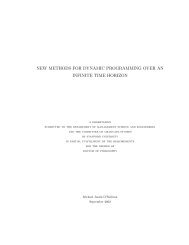
Fig. 1 shows one particular network for producing<br />
reverberation. We like this topology for several reasons:<br />
1) It has simple knobs, which easily control particular<br />
aspects of the reverberated sound, such as input and decay<br />
diffusion (decorrelation), decay rate, high-frequency<br />
damping, and input signal bandwidth. 2) The style of<br />
the topology is more computationally efficient than most<br />
others known. 3) It has demonstrated applicability to a<br />
broad range of signal sources.<br />
We selected the network in Fig. 1 for presentation<br />
because it is the smallest reverberation network we found<br />
(in memory and complexity) that is good sounding. We<br />
believe that there must be a limitless variety of such<br />
networks, however. The question naturally arises as to<br />
why the simple digital network shown produces such<br />
convincing reverberation. We can answer this only<br />
qualitatively.<br />
Consider the plucked string of a violin. Its envelope<br />
may be described as having a coherent exponential decay.<br />
It is this character that is theorized to be one of the<br />
primary discriminants of nonreverberated sound. Reverberating<br />
this sound, on the other hand, would tend to<br />
randomize the string envelope and phase, producing a<br />
bumpier, extended, more diffuse and dynamic decay.<br />
This oversimplified qualitative description of the process<br />
of reverberation has actually found its way into<br />
early commercial products. Long before DSP chips<br />
could be integrated into sampler type synthesizers, reverberated<br />
sampled sound was simulated by altering the<br />
decay characteristics of recorded dry samples by randomizing<br />
an overlaid envelope applied at playback.<br />
While not absolutely convincing, this kind of aural cue<br />
2 Jot recently formulated an analytical design method for<br />
recursive reverberators. The work is based on a unitary (lossless)<br />
feedback loop in a state-space network, where he claims<br />
arbitrary time and frequency density<br />
3 This discussion is adapted from conversations with Barry<br />
Blesser and David Griesinger and is supplemented by Appendix<br />
1 in Section 1.5<br />
J. Audio Eng Soc., Vol. 45, No. 9, 1997 September 661
DATTORRO<br />
was enough to cause pioneers [3]-[5] to question the<br />
premise of Schroeder's precipitative work with delay<br />
lines at Bell Labs during the early 1960s.<br />
One can deduce from Schroeder's work [7] that to<br />
achieve the ideal of colorless reverberation, the eigentone<br />
4 density of the network needs to approach 3 per<br />
PAPERS<br />
hertz, It can also be theorized that the limit on the number<br />
of achievable eigentones is proportional to the total<br />
delay-line memory [4]. From our current perspective we<br />
4 An eigentone of a network in this context is a circuit<br />
resonance.<br />
xR<br />
z'~<br />
predelay<br />
I<br />
bandwidth<br />
1. - bandwidth<br />
,nputdiffusion 1 / / 7nputdi"usion I<br />
--r--~ J ~ ~<br />
in0ut0,.os,on<br />
,o0 ,0,..sion<br />
672 + EXCURSION ]<br />
908+ EXCURSION J<br />
note sign _ ,j .~.<br />
decay diffusion 1 ' diffusion 1<br />
1. - damping<br />
O<br />
decay<br />
damping<br />
;at<br />
O<br />
z.3 o<br />
decay diffusion 2<br />
|<br />
Fig. 1. Simplified plate-class reverberation topology in the style of Griesinger. For output tap structure (YL, YR) see Table 2.<br />
Delay-line taps at nodes 24 and 48 are modulating.<br />
662 J. Audio Eng, Soc, Vol 45, No. 9, 1997 September
PAPERS<br />
know that emulation of physical spaces can be convincingly<br />
performed using sample rates as low as 20-24<br />
kHz. This is true because of typically rapid acoustical<br />
absorption in the high-frequency region, and because<br />
the desired output is a mix with the dry input signal. This<br />
bandwidth would then require about 30 000 eigentones,<br />
hence about 64K words of delay-line memory. In the<br />
1960s, that amount was not economical. 5<br />
In reverberator design, while a good general rule regarding<br />
delay-line memory is certainly "the more the<br />
better" [4], the efficient reverberation network shown in<br />
Fig. 1 stands as a testimony 6 that Schroeder's eigentone<br />
density criterion, predicting about 88K words of memory,<br />
is not a hard and fast rule. Of at least equal importance<br />
are the decorrelation of the decay and the associated<br />
time density of the echoes, that is, one must achieve<br />
a balance between eigentone density and echo density.<br />
1.2 Color<br />
On the other hand, our reverberation network's signal<br />
response is not colorless. Empirically we find that some<br />
of the most sought after commercial reverberators are<br />
somewhat colored in their frequency responses. This<br />
means that their outputs impose some conspicuous audible<br />
resonances upon the input signal. Consequently it is not<br />
unusual to find as many musicians and recording engineers<br />
who like a particular reverberator as those who do not.<br />
We also find that some recording engineers do not<br />
want an accurate emulation of a physical space, because<br />
the reflection density takes too long to build. Instead,<br />
they sometimes want instantaneous high-density reflections<br />
with smooth exponential decay of the envelope,<br />
having randomization in only the phase trail. This desire<br />
most closely describes the plate class of reverberators,<br />
which we present here.<br />
1.3 Discussion of the Reverberator<br />
Scrutinizing the reverberation topology in Fig. l, we<br />
can break it down into a cascade set of four input dif-<br />
5 The Lexicon model 224 digital reverberation system introduced<br />
in 1979 originally possessed only 16K words of memory,<br />
operating at a sample rate of 20 kHz. That memory amount<br />
doubled shortly thereafter. The Elecktromesstechnik Wilhelm<br />
Franz KG EMT-250 digital reverberator distributed in the<br />
United States by Gotham Audio Corporation beginning in<br />
1977, operated at a sample rate of 32 kHz, having only 8K<br />
words of memory. The precursor to this machine is described<br />
in [10, ch. 2].<br />
6 Given a 30-kHz sample rate and having only 22K words<br />
of memory (not including predelay).<br />
EFFECT DESIGN<br />
fusers (the lattices) followed by another set of four tank<br />
diffusers, the latter arranged so as to feed back on themselves<br />
globally. The first set of diffusers acts to quickly<br />
decorrelate the incoming sound somewhat, preparing<br />
that sound to be looped indefinitely in the holding tank<br />
formed by the second set of diffusers. What we hear<br />
comes from a large set of output taps (not shown) located<br />
within the tank.<br />
1.3.1 Input Diffusers<br />
All the diffusers are all-pass filters having the topology<br />
of a lattice. The purpose of the four input diffusers<br />
is to decorrelate the incoming signal quickly before it<br />
reaches the tank. The tank recirculation can sometimes<br />
become perceptible as strong cyclic events if the input<br />
signal is not preconditioned in this manner. This function<br />
becomes especially important for the successful reverberation<br />
of percussive sounds. One may think of this<br />
function as signal-phase randomization, to reduce peakedness<br />
and other strong features of the input waveform.<br />
No diffusion corresponds to zero-valued all-pass coefficients,<br />
while coefficient magnitudes close to unity produce<br />
buzzing that is local to the afflicted all-pass filter.<br />
Optimum diffusion for the all-pass filter lies somewhere<br />
in a region closer to 10.51 than to the extreme values of<br />
the coefficients. The preset values given in Table 1 were<br />
determined by trial and error.<br />
1.3.2 Tank<br />
We identify the reverberation tank as the recirculating<br />
four lowest diffusers in Fig. 1. We call it a tank because<br />
its purpose is to trap the incoming sound by making it<br />
recirculate through the global figure eight. The four decay<br />
coefficients determine the rate of decay. When the<br />
decay coefficients are set very close to 1.0 (and the<br />
damping filter within the tank is turned off), the sound<br />
will remain held in the tank indefinitely. That in itself<br />
is a neat effect, but unless the sound metamorphoses<br />
while in the tank, it is easy for us to detect the looping<br />
pattern of sound. The purpose of the diffusers within<br />
the tank, then, is to eliminate any aural pattern in the<br />
recirculation. The tank diffusers are not always successful<br />
(being signal dependent), and their settings are critical<br />
to achieve an overall exponential decay; everything<br />
must be set by ear.<br />
The tank, in summary, is a simple device whose purpose<br />
it is to alter the tail of a decaying sound, as mentioned<br />
already. The tank diffusers have been further<br />
grouped into pairs labeled by the knobs "decay diffusion<br />
Table 1. Reverberation parameters default.<br />
Sample rate F s = 29761 Hz<br />
EXCURSION = 16<br />
decay = 0.50<br />
decay diffusion 1 = 0.70<br />
decay diffusion 2 = 0.50<br />
input diffusion 1 = 0.750<br />
input diffusion 2 = 0.625<br />
bandwidth = 0.9995<br />
damping = 0.0005<br />
Maximum peak sample excursion of delay modulation<br />
Rate of decay<br />
Controls density of tail<br />
Decorrelates tank signals; decay diffusion 2 = decay + 0.15, floor = 0.25, ceiling = 0.50<br />
Decorrelates incoming signal<br />
High-frequency attenuation on input; full bandwidth = 0.9999999<br />
High-frequency damping; no damping = 0.0<br />
J. Audio Eng. Soc, Vol. 45, No. 9, 1997 September 663
DATTORRO<br />
1" and "decay diffusion 2." The tank diffusers have<br />
overlapping functionality. The dichotomy we make is<br />
aurally subtle and pertains to the temporal location of<br />
the diffusers in the tank with respect to a stereo tank<br />
input, that is, exactly when they diffuse the tank signal<br />
with respect to the signal onset. The effect of these<br />
knobs is best observed using a percussive input, or what<br />
Griesinger refers to as a "pink click.'7<br />
1.3.3 All-Pass Lattice Topology<br />
Each diffuser has been given the topology of a twomultiplier<br />
lattice. The eight lattices shown in the reverberator<br />
schematic in Fig. 1 are used in this reverberation<br />
effect as all-pass filters, each having a long impulse<br />
response time.8 The two coefficients within each individual<br />
lattice must remain identical to maintain the allpass<br />
transfer function, which is insensitive to coefficient<br />
quantization. The recommended range of these coefficients<br />
is from 0.0 to 0.9999999 (q23; see <strong>Part</strong> 3, Section<br />
9.1, Appendix 7) If the lattice coefficients should exceed<br />
1.0, instability would result. Making them both negative<br />
will change the character of the impulse response 9 but<br />
does not destroy the all-pass transfer. This change in<br />
character is exploited in the lattices having the coefficients<br />
called "decay diffusion 1" in the schematic. This<br />
character change further enhances the dichotomy between<br />
the two pairs of tank diffusers.<br />
All-pass response is the forced (steady-state) response<br />
of each lattice output with respect to its own input.l~<br />
Because the impulse response of each individual lattice<br />
within the reverberator schematic is so long, in some<br />
cases the integration time constant of the human hearing<br />
system is exceeded. This means that an all-pass filter<br />
output may be perceived as discretized events, that is,<br />
not all pass.<br />
This all-pass lattice topology tends to clip prematurely<br />
at internal nodes, so the input to each lattice cannot be<br />
presented with a full-scale signal at all frequencies. We<br />
like this all-pass lattice, however, because it is efficient<br />
in its implementation.<br />
1.3.4 Magnitude Truncation<br />
Lattices produce distinct low-level tones, after the<br />
input signal has been removed, known as zero-input<br />
limit cycles. The origin of these tones stems from ongoing<br />
signal quantization in a recursive topology. The<br />
7 A click source having a pink spectrum.<br />
s The impulse response is that of an upsampled first-order<br />
all-pass filter. This filter basically has an exponentially decaying<br />
impulse response with or without a multiplicative factor<br />
n 1<br />
of ( - 1) - , depending on the sign of the coefficient. The upsampling<br />
factor L is determined by the number of samples in<br />
the lone delay line z -L within the lattice. The up-sampling<br />
process inserts L - 1 zeros between every sample of the<br />
impulse response of the corresponding first-order all pass filter.<br />
9 Via the multiplicative factor (-1) "-~ on the impulse<br />
response.<br />
~0 The reverberation network as a whole does not have an<br />
all-pass transfer function, although we would like that to be<br />
the case. Smith [9, pp. 1-28] has found a way to make an<br />
entire reverberation network all pass. Smith's method is based<br />
on the interconnection of lossless waveguides.<br />
PAPERS<br />
spontaneous tones can be eliminated through the use of<br />
magnitude truncation (truncation toward zero; see <strong>Part</strong><br />
3, Section 9.2, Appendix 8) of the double-precision intermediate<br />
results written out to single or lower precision<br />
delay-line memory. Magnitude truncation is well known<br />
to subdue limit cycles in digital networks composed of<br />
ladders and lattices [9].<br />
Only the recursive circuits require magnitude truncation.<br />
In Fig. 1 the write to the predelay does not require<br />
magnitude truncation. If delay-line memory is 24 bits<br />
in width, then the need for magnitude truncation is obviously<br />
lessened when compared to having delay-line<br />
memory of only 16 bits in width.<br />
Magnitude truncation, in the specific case of reverberator<br />
tank topologies employing lattice or ladder all-pass<br />
circuits, can reduce the network noise floor by 12-24<br />
dB after the input signal is removed. The reason this is<br />
true is that the predominant noise mechanism is zeroinput<br />
limit-cycle oscillation,11 a multiplicity of which is<br />
perceived as a whooshing ocean noise floor. The magnitude<br />
truncation makes the reverberator output eventually<br />
go to absolute zero, two's complement. The disadvantage<br />
to its use is that the THD + N (total harmonic distortion<br />
+ noise) of a steady-state sinusoid through the<br />
linear reverberator network can be increased by anywhere<br />
from 0 to 6 dB.<br />
1.3.5 First-Order Filters<br />
The three single-pole low-pass filters used for input<br />
signal bandwidth control and reverberator tank damping<br />
will not clip prematurely at any node [11, ch. 11.3],<br />
[12, p. 857] when implemented as direct form I. The<br />
damping filters cause high frequencies to decay within<br />
the tank more quickly than low frequencies. On the<br />
input-bandwidth filter, the bandwidth coefficient tracks<br />
the cutoff frequency. In contrast, the damping coefficient<br />
is high when the damping filter cutoff frequency is low.<br />
The recommended range of these coefficients is from 0.0<br />
to 0.9999999 (q23; see <strong>Part</strong> 3, Section 9.1, Appendix 7).<br />
Because they are all first-order low-pass filters, any<br />
low-level zero-input limit cycles they might produce<br />
would be at dc, that is, they will not produce tones like<br />
the lattices [11, ch. I 1.5]. Any signal-truncation noise<br />
power spectrum generated by the filters themselves will<br />
be centered at de, since it follows the pole frequency.<br />
The peak gain of the noise power spectrum is not great<br />
because typically the lone pole is relatively far from the<br />
unit circle. 12<br />
1.3.6 Output Tap Points<br />
From the pseudocode note that the delay-line tap<br />
structure forming the stereo output signal YL and YR is<br />
an all wet (reverberated) signal (Table 2). This particular<br />
output tap structure is characteristic of the plate emula-<br />
II Here we use the term "limit cycle" in the classical DSP<br />
sense.<br />
12 If instead the filters were high pass, limit-cycle tones<br />
might be produced at Nyquist while the truncation noise power<br />
spectrum would also be concentrated there.<br />
664 J. Audio Eng Soc., Vol. 45, No 9, 1997 September
PAPERS<br />
don class of reverberation networks. 13 Also note that the<br />
output tap structure produces a synthetic stereo image<br />
because the stereo input is converted to a monophonic<br />
signal at the reverberator input for this particular topology.<br />
Normally, the desired output is a mix of the stereo<br />
reverberated signal YL and YR with the original (dry, fullbandwidth)<br />
stereo input signal x L and XR.<br />
1.3.7 Delay Modulation<br />
Linear interpolation or, better yet, all-pass interpolation<br />
(as discussed in <strong>Part</strong> 2, Section 5) can be efficiently<br />
employed to modulate slowly x4 the nominal tap point of<br />
the two indicated delay lines in the schematic. A slight<br />
modulation will introduce undulating pitch change into<br />
the tank. For signals with much high-frequency content,<br />
such as drum sets, these built-in modulators serve to<br />
break up some pretty audible modes, that is, the amount<br />
of tank diffusion is effectively increased.<br />
Barring air currents and temperature fluctuations,<br />
there is no analogue to this modulation process in a<br />
real room (unless the walls are moving). Without the<br />
modulation, we may well describe the imaginary space<br />
emulated by the given digital network as being enclosed<br />
by a picket fence. The slow modulation serves to increase<br />
effectively the sheer number of resonances (eigentones,<br />
modes of oscillation, picket density) in the tank.<br />
The number of resonances in a real room, hall, or plate<br />
is probably far beyond what is existent in our little (nonmodulating)<br />
reverberation network. In the case of drum<br />
la The physical "plate," actually resident in some contemporary<br />
recording studios, fills a small room in some embodiments.<br />
The best plates are constructed using a solid g.old foil.<br />
The input signal is typically injected onto the plate via one or<br />
two transducers, while each output is the sum of multifarious<br />
signal taps, each tap transduced at a different location on<br />
the plate.<br />
14 At a rate on the order of 1 Hz, and at a peak excursion<br />
of about 8 samples for a sample rate of about 29.8 kHz.<br />
Table 2. Output taps.<br />
/********* left output, all wet *********/<br />
accumulator<br />
accumulator<br />
accumulator<br />
accumulator<br />
accumulator<br />
accumulator<br />
= 0.6 X node48_541266]<br />
+= 0.6 x node48_54[2974]<br />
-= 0.6 X node55_59[1913]<br />
+= 0.6 X node59_63[1996]<br />
-= 0.6 X node24_30[1990]<br />
-= 0.6 x node31_33[187]<br />
YL = accumulator - 0.6 X node33_39[1066]<br />
/********* right output, all wet *********/<br />
accumulator<br />
accumulator<br />
accumulator<br />
accumulator<br />
accumulator<br />
accumulator<br />
YR = accumulator<br />
= 0.6 X node24_30[353]<br />
+= 0.6 X node24_30[3627]<br />
-= 0.6 X node31_33[1228]<br />
+= 0.6 X node33_39[2673]<br />
-= 0.6 X node48_54[2111]<br />
-= 0.6 X node55_59[335]<br />
- 0.6 X node59_63[121]<br />
J. Audio Eng See., Vol 45, No 9, 1997 September<br />
EFFECT DESIGN<br />
sets, the modulation is a godsend. In the case of piano,<br />
the modulation, though slight, may be objectionable because<br />
of a perceived vibrato.<br />
Ideally, all the delay lines in the tank diffusers should<br />
be modulated using different modulation rates and<br />
depths. In that case, the diffusion burden becomes more<br />
distributed. Hence the required rate and depth of modulation<br />
are lessened for each diffuser. When computation<br />
time is a constraint, then one should preferentially select<br />
the stereo pair of the diffusers appearing earliest in the<br />
tank, as we have, to maximize the increase of effective<br />
resonances. In this case, the same rate and depth are<br />
used for each diffuser in the pair, but we use a quadrature<br />
oscillator to decrease the correlation. (Sinusoidal oscillators<br />
are discussed in Section 7.) The differing delayline<br />
lengths of all the diffusers also serve to decrease<br />
the correlation.<br />
As explained in Section 4; linear interpolation for delay<br />
modulation will introduce time-varying low-pass filtering<br />
as an artifact, thus supplying some unaccounted<br />
damping to the tank. All-pass interpolation overcomes<br />
this particular problem and is perfectly applicable to<br />
reverberators because the required pitch change is<br />
microtonal. 15<br />
1.4 Conclusion<br />
Choosing a particular reverberator for a particular application<br />
is commonplace, and purveyors of such equipment<br />
have been known to purchase an audio signal processing<br />
box just to acquire one particular algorithm.16<br />
At some level, the choice of reverberator becomes a<br />
matter of taste, much like art. There is no one universal<br />
reverberation network that satisfies everyone for each<br />
and every application; we speculate that there never<br />
will be.<br />
1.5 Appendix 1: Reverberation Recollections<br />
Dear Jon,<br />
What you wrote was fine, but it stimulated my memory<br />
of additional snippets. Feel free to use what you<br />
want.<br />
I had a personal conversation with Manfred Schroeder<br />
in the late 1970s and I asked him the question about<br />
what the phrase "maximal incommensurate" delay values<br />
meant, as it appeared in one of his reverberation<br />
papers. His answer was particularly interesting. This is<br />
a paraphrase based on my tired memory:<br />
We did the electronic reverberation for amusement<br />
because we thought it would be fun. Since it took the<br />
better part of a day to do 10 seconds of reverberation,<br />
we only ran one sample of music. The notion of delay<br />
time selections was random in that we just picked a<br />
bunch of numbers and there was no mathematical ba-<br />
15 The sinusoidal low-frequency oscillator driving the<br />
modulator must have a rate of update that is the same as<br />
the audio sample rate, that is, the two sample rates must be<br />
identical. Otherwise, aliasing artifacts will be introduced<br />
into the audio signal path.<br />
16 Much like buying a Compact Disc because one likes<br />
the title track.<br />
665
DATTORRO<br />
sis. We just wanted to prove it could be done.<br />
He never related this work to his more profound mathematical<br />
and perceptual research, specifically the work<br />
on the required 3-eigentone/Hz density and the frequencyphase<br />
statistics in a random physical space.<br />
The original EMT reverberator, model 250, operating<br />
at a 32-kHz sample rate, used a main memory of 8K<br />
words, and the required eigentone density was emulated<br />
entirely by randomizing delay lines. Another interesting<br />
fact is that colorless reverberation, using all-pass structures,<br />
is perceptually not colorless. Even white noise<br />
passed through an all pass will not sound like real white<br />
noise. When passed through many such all-pass structures,<br />
it in fact sounds like a machine shop rather than<br />
random noise. It still measures spectrally flat. The reason<br />
is that frequency regions get bunched in time. It is very<br />
much like a chirped sine wave in radar having a purely<br />
fiat spectrum but being very different from white noise.<br />
The second- and higher order statistical terms out of an<br />
all pass are very, very different from a real random<br />
process. The utility of an all pass is to pass all frequencies<br />
through so that each all pass can see the same spectral<br />
density, otherwise comb peaks would align and dominate.<br />
Parallel structures of non-all-pass elements<br />
achieve a similar issue in that each structure gets fed<br />
the full spectrum. All-pass elements are more critical<br />
for small delay values. An all pass within a larger loop<br />
must be used with great care since it has a sinelike<br />
variation in group delay. Hence the effective loop time<br />
and reverberation time vary with frequency. After many<br />
trips around the loop, the result will be very colored.<br />
Schroeder's had several analyses about reverberation,<br />
but his 3-eigentone/Hz theory, which maps to 3 seconds<br />
of memory, can be looked at in many ways. His result<br />
was empirical, based on listening tests. Consider two<br />
eigentones, or poles, separated by 1 Hz and located in<br />
the s plane with a real part of - 10 Hz. When excited,<br />
this will produce two damped exponentially decaying<br />
frequencies which differ by 1 Hz. Hence there will be<br />
a 1-Hz envelope beat, which is clearly audible. Now<br />
add other eigentones, randomly spaced but still at a<br />
distance of - 10 Hz. Assume 10 such eigentones. All<br />
of them will beat with each other, producing a random<br />
envelope with a spectrum that is crudely flat from 0 to<br />
10 Hz. One can do this simulation in closed form with<br />
variable excitation of each eigentone. Schroeder's result<br />
actually depends on the nominal reverberation time since<br />
that determines how many eigentones will get excited<br />
by a narrow-band input. In the early reverberation boxes,<br />
with only 150 ms of reverberation, typically only a few<br />
tones would be excited. The envelope had a clear periodicity<br />
of 6 Hz on average. It sounds bad. Some regions<br />
had only two eigentones excited with a distance of 2<br />
Hz, which was even worse. Development was much<br />
more exciting with such limited memory. Today one<br />
can use 1 second of DRAM memory. Many simpler<br />
structures will thus produce good reverberation.<br />
The perceptual simulations deviated from physical<br />
reality in many ways. For example, a natural threedimensional<br />
space has an increasing eigentone density<br />
PAPERS<br />
that is proportional to the square of frequency. All electronic<br />
simulations tend to have a constant density. The<br />
reason is that in a three-dimensional space, the speed of<br />
sound along a dimension is proportional to the sine of the<br />
wave front direction, whereas in an electronic structure it<br />
is always constant.<br />
That is what I remember, so do what you wish with<br />
it. Best of luck.<br />
Sincerely yours,<br />
BARRY BLESSER<br />
Blesser Associates<br />
Electronics & Software Consultants<br />
Belmont, MA 02178, USA<br />
2 MUSICAL FILTERING<br />
The first-order recursive filter is by far the safest and<br />
most economical choice. Low in noise, it should be used<br />
wherever possible, and in cascade if necessary. For the<br />
design of shelving filters, which are conventionally first<br />
order, refer to [ 13]. When a filter having a steeper transition<br />
band is desired, it is usually sufficient to employ a<br />
second-order filter. Musical filters do not often see orders<br />
higher than that. 17<br />
In this section we discuss filtering requirements for<br />
musicians whose criteria are quite different from those<br />
of the electronics engineer. Our treatment of filtering<br />
will consider only the second-order case and predominantly<br />
all-pass topologies. The applications of these filters<br />
are broad; we note a particular suitability to parametric<br />
equalization. The more involved topic of truncation<br />
noise recirculation is not discussed in this section, although<br />
we do discuss limit cycles and internal signal<br />
overflow. The more curious reader is referred to [12] to<br />
find remedies for truncation noise within the direct form<br />
I topology.<br />
For those readers new to digital filtering, the eminent<br />
theoretician, practitioner, and mentor of DSP and electronic<br />
music, Julius O. Smith, presents a splendid introduction<br />
to classical digital filter theory in [15, ch. 2],<br />
requiring only basic mathematical skills. Strawn's audio<br />
signal processing book [15] is written from the musician's<br />
standpoint, hence it is highly recommended.<br />
2.1 Filter (O) Selectivity<br />
Electronics engineers are accustomed to think of digital<br />
filters analytically in terms of pole-zero constellation<br />
and locus, cutoff frequency, passband ripple, transition<br />
band or slope, stopband attenuation, and so on. Musicians<br />
and recording engineers are more comfortable<br />
thinking in terms of filter parameters--gain or cut, center<br />
frequency, filter Q (selectivity) or bandwidth. Formally,<br />
filter Q is defined as the positive quantity<br />
t% _ t% (1)<br />
Q-Ao~ o~2-COl<br />
17 When a filter that is steeper than second order is required,<br />
it is advisable to construct it as a cascade of second-order<br />
sections. That will mitigate any coefficient sensitivity or truncation<br />
noise problems [ 11, oh. 11.4-11.6], [ 14].<br />
666 J. Audio Eng. Soc., Vol. 45, No. 9, 1997 September
PAPERS<br />
that is, the center frequency divided by the bandwidth.<br />
The bandwidth is determined from the particular definition<br />
of the cutoff frequencies o h and to2 (in radians).<br />
Traditionally the cutoff frequency coincides with an absolute<br />
half-power level. In the archetypal case of a steep<br />
unity-gain (0-dB) low-pass filter we recall this level as<br />
corresponding to the frequency at which the magnitudesquared<br />
response reaches -3.01 dB [= 10 logx0(1/2)].<br />
But shallow audio filters may not have an absolute halfpower<br />
level. So we must refine the definition of cutoff<br />
frequency in terms of half-power excursion, not an absolute<br />
level [16].<br />
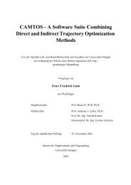
Take, for example, the cut filter magnitude-squared<br />
response shown in Fig. 2. This example response has a<br />
Q of 2. We define the two musical cutoff frequencies<br />
as corresponding to the level at which<br />
1 -IHie>)12 1<br />
I - IH~(eJ'%)IZ = 2" (2)<br />
We must solve this equation for to. There are two solutions,<br />
tol and %. Referring to Fig. 2, this equation instructs<br />
us to measure the bandwidth halfway down the<br />
trough of the magnitude-squared response. This makes<br />
intuitive sense. We cannot use the traditional definition<br />
of cutoff frequency for this example because the trough<br />
is not deep enough. But note that if Ino(eJ%12 = 0 (notch<br />
filter), then the solution to Eq. (2) would correspond to<br />
the traditional definition of cutoff frequency.<br />
The situation is pretty much the same for the resonator.<br />
Whereas the cut filter approaches unity asymptotically<br />
at z = • 1, the resonator is loosely defined as a<br />
second-order peaked filter having a peak gain normalized<br />
to unity at its center frequency. The resonator is easily<br />
formulated such that its magnitude-squared response is<br />
an exact flip of the corresponding cut filter about the<br />
horizontal half-power excursion line, that is, it is sym-<br />
EFFECT DESIGN<br />
metrical with the cut filter. We shall shortly see how.<br />
This is the reason why many of the numbers are exactly<br />
the same in both Figs. 3 and 2.<br />
For the resonator (rather, the normalized boost filter)<br />
we acquire the two musical cutoff frequencies % and<br />
%, solving the slightly different equation<br />
1 -IHb.o=(eJ')l 2 1<br />
1 -lHboo= (• 1)1 = 2"<br />
Like before, the bandwidth is measured halfway up the<br />
peak of the magnitude-squared response in Fig. 3. Again<br />
we note that if IHb.o= (- 1)12 = 0 (perfect resonator),<br />
then the solution to Eq. (3) corresponds to the traditional<br />
definition of cutoff frequency.<br />
Having gained an understanding of musical filter Q,<br />
we begin with two unique and musically useful digital<br />
filter transfer functions, which precisely fit our definition<br />
of filter selectivity.<br />
2.2 Cut Filter<br />
When constructing a notch filter, we expect there to<br />
be an absolute zero of transmission at some selected<br />
frequency in its transfer function. If we use a filter that<br />
only has zeros (that is, no poles), we can indeed make<br />
a notch. The problem with this approach is that the rest<br />
of the magnitude response would not be very fiat, as we<br />
might like it to be. We might also like a "surgical"<br />
notch, one that has high selectivity. Fig. 4 is an example<br />
showing the magnitude transfer of a badly designed<br />
notch filter evaluated along the unit circle in the z plane.<br />
The zero radius is R = 1, whereas the zero angle is<br />
0 = 1 rad. This transfer function has two trivial poles<br />
atz --- 0.<br />
The magnitude response shown in Fig. 4 would pretty<br />
much obliterate a musical signal, especially because of<br />
the gain at high frequencies. Note that if the zero were<br />
(3)<br />
IHc(eJ~<br />
0.8<br />
0.6<br />
half-power excursion points<br />
(0.769836, 0.834711 ) (1.269836, 0.834711)<br />
/ t<br />
bandwidth ~ I -<br />
cut depth 2 = 0.669421<br />
I<br />
power excursion<br />
Absolute<br />
0.4<br />
1 - 0.834711<br />
1 - 0.669421<br />
= 1/2<br />
0.2<br />
mc<br />
1.269836 - 0.769836<br />
=2=Q<br />
tOc=l<br />
i , , i , i , , , , i , ,<br />
0.5 1 1.5<br />
Fig. 2. Cut filter excursion ~ 1.7 dB.<br />
, i l l , i l l<br />
2.5 3<br />
J Audio Eng. Soc., Vol. 45, No 9, 1997 September 667
- 1/2<br />
DATTORRO<br />
moved to a new fixed frequency, the rest of the magnitude<br />
response would change its shape in an undesirable<br />
way. Hence this particular notch filter is not very useful<br />
for surgical filtering.<br />
In [13] it was shown how to make the passband portions<br />
of the notch filter flat, and how to achieve high<br />
selectivity. This is accomplished by adding nontrivial<br />
poles. The result is illustrated in Fig. 5 and expressed<br />
in the transfer function<br />
1 + 2~/z -1 + z -2<br />
H.(z) = (1 + 13) 1 +~/(1 + 13)z -1 + 13z -2"<br />
(4)<br />
equation<br />
1 - z =2<br />
Hr(z) = (1 - [~) 1 4- ~/(1 "]- [~)z -1 + [~z -2" (5)<br />
This filter has a peak gain that is always precisely 1,<br />
regardless of the center frequency. This is characteristic<br />
of a resonator. The two zeros make the skirts of the<br />
I1 - 2Rcos(0) z -1 + R 2z-21 @z=e j~<br />
PAPERS<br />
This notch filter [Eq. (4)] has an absolute zero having<br />
controllable selectivity there at its center frequency,<br />
while its magnitude at dc and Nyquist is always 1, regardless<br />
of the center frequency. We must determine<br />
how to obtain a trough of arbitrary depth while maintaining<br />
the other attributes. This would be called a parametric<br />
cut filter. Before we do that, however, we look<br />
at the resonator, which is an exact powerwise flip of this<br />
notch filter about a horizontal.<br />
2.3 Resonator<br />
One use of a perfect resonator in electronic music is<br />
to synthesize ping sounds via impulsive excitation. We<br />
discuss a more general resonator for use as a musical<br />
filter. It is easy to construct a simple resonator using<br />
only poles. But such an approach has problems similar<br />
to those we encountered with the all-zero notch filter,<br />
especially with regard to shape, selectivity, and magnitude.<br />
In particular, the peak magnitude will vary as the<br />
center frequency is changed to new fixed values.<br />
In [11, ch. 4.3] it was shown how to normalize the<br />
height of the resonator peak magnitude as the center<br />
frequency changes, namely, by adding two zeros, one<br />
at Nyquist and the other at dc. This musically useful<br />
result is illustrated in Fig. 6 and expressed by the<br />
2.<br />
i.<br />
0.5<br />
1<br />
Absolute<br />
0.8<br />
0.6<br />
0.4<br />
:" O.<br />
0.5 1 1.5 2 2.5 3<br />
Fig. 4. Poor notch filter; R = 1, 0 = 1.<br />
IHa(eJ~<br />
0.5 1 1.5 2 2.5<br />
Fig. 5. Notch filter; Q = 2, to c = 1.<br />
O)<br />
to<br />
IHbnorm(eJ~ 2<br />
1<br />
half-power excursion points<br />
(0 769836, 0.834711) (1 269836, 0 834711)<br />
[ /<br />
0.8<br />
\ \ I / / power excursion<br />
0.6<br />
Absolute<br />
0.4<br />
0.2<br />
- skirt depth 2 = 0.669421 .....<br />
1 - 0.834711<br />
1 - 0.669421<br />
s c<br />
1 269836 - 0.769836<br />
=2=Q<br />
~c = 1<br />
. . . . o15 . . . . { . . . . 115 . . . . '2.5 3<br />
Fig. 3. Resonator excursion ~ 1.7 dB.<br />
668 J Audio Eng Soc., Vol 45, No 9, 1997 September
PAPERS<br />
magnitude-squared response go to zero at the extremities.<br />
When the extremities reach zero, we call this the<br />
perfect resonator [Eq. (5)]. We must determine how to<br />
make skirts of arbitrary depth--the resonator. We must<br />
also determine how to place the skirts at absolute magnitude<br />
1 while achieving arbitrary peak heights; that would<br />
be called a parametric boost filter. We have yet to define<br />
~/and 13.<br />
2.4 Musical Filter Topology<br />
The two transfer functions H,(z) and Hr(z) have some<br />
desirable theoretical and practical properties. First, there<br />
is a strong bond between Eqs. (4) and (5). Because their<br />
denominators are identical, there exists one circuit that<br />
can generate both. Second, there is a simple relationship<br />
between the coefficients 13 and ~/and the musical filter<br />
parameters toe and Q.<br />
Consider the all-pass lattice topology shown in Fig.<br />
7. It has the all-pass transfer function<br />
A(z) - Y(z) 13 -t- ~(1 q- 13)z -1 Jr- z -2<br />
X(z~) - 1 + ~/(1 + 13)z -1 + [~z -2" (6)<br />
Some characteristics of the all pass filter are summarized<br />
in Fig. 8 and the equations<br />
[A(eJ'~ = 1, A(- 1) = !, A(e j~ = - 1 .<br />
It is interesting that the non-minimum-phase all-pass<br />
filter will shortly become integral to a parametric filter<br />
that is indeed a minimum-phase design. We also note<br />
in passing that the transfer to Dr(z ) from the input comprises<br />
only the denominator (the poles) of A(z),<br />
(7)<br />
EFFECT DESIGN<br />
Back to the problem at hand, it is easily proven that<br />
n,(z) -<br />
1 - A(z)<br />
2 (8)<br />
1 + A(z)<br />
H.(z) - 2 (9)<br />
Substituting Eq. (6) into Eqs. (8) and (9), we can derive<br />
Eqs. (5) and (4). This means that we can construct notch<br />
and perfect resonant filters from an all-pass filter. We<br />
only have left to show that using the all-pass filter we<br />
can construct cut, resonant, and boost filters as well. We<br />
will use the fact [Eq. (7)] that at the critical frequency<br />
~ = arccos(-~) (10)<br />
the all-pass filter output is 180 ~ out of phase with respect<br />
to a steady-state sinusoid at its input. This critical frequency<br />
becomes the normalized center frequency r =<br />
2~rfcT (with T being the sample period) for all filter<br />
types employing the topology shown in Fig. 9.<br />
In Fig. 9 we have introduced a new control coefficient<br />
k. When k = 0, the network in Fig. 9 implements the<br />
notch [Eq. (9)] exactly, and when k = 2, this same<br />
network implements the perfect resonator [Eq. (8)] exactly.<br />
Within these bounds, this control (for k < 1) gives<br />
us the ability to specify the depth of the cut, leaving the<br />
magnitude at the extremal frequencies equal to 1. Using<br />
the same network for the resonator, we can control the<br />
depth of the skirts (when k > 1), leaving the absolute<br />
~ "Sk[ A(eJ ~ )<br />
Dr(g ) =<br />
X(z)<br />
1 + ~/(1 + 13)z -1 q- 13 Z-2.<br />
IHr(eJC~<br />
(oc=l<br />
-3 -2 -1 -2~''"~ ....<br />
0)<br />
1<br />
Absolute<br />
0.8<br />
0.6<br />
Fig. 8. All-pass radian phase responses.<br />
0.4<br />
0.2<br />
1/2 '~~-, 1+-~1-kl<br />
0.5 1<br />
X,z,<br />
1.5 2 2.5 3<br />
Fig. 6. Perfect resonator; Q = 2, co c = 1.<br />
O)<br />
Fig. 9. Cut, notch, or resonator type filter.<br />
Y(z)<br />
Fig. "7. Lattice second-order all-pass filter.<br />
J. Audio Eng. Soc., Vol. 45, No 9, 1997 September 669
DATTORRO<br />
peak frequency magnitude at precisely 1. These actions<br />
explain the unusual looking normalization coefficient at<br />
the output.<br />
The action of the control coefficient k is characterized<br />
in Table 3 and illustrated in the magnitude-squared responses<br />
of Figs. 10 and 11. The cut depth [Eq. (11)]<br />
and the skirt depth [Eq. (12)] must be squared to resolve<br />
with Figs. 10 and 1 1, respectively,<br />
PAPERS<br />
These depth equations are easily deduced from Eqs. (10)<br />
and (7) and are independent of the center frequency.<br />
The center frequency is unequivocally determined by<br />
Eq. (10) for these cut, notch, resonator, and perfect<br />
resonator filters shown in Figs. 10 and 1 1. This center<br />
frequency corresponds to the peak or trough extremum<br />
of the magnitude transfer evaluated on the unit circle in<br />
absolute cut depth =<br />
1 - (1 - k) _ k<br />
l+ll-kl 2-k<br />
;0~
PAPERS<br />
EFFECT DESIGN<br />
tor, and perfect resonators by the equations<br />
(1 + [3) 2 cos (t%) + ,- ([3 - 1)N/2(1 + [32) _ (1 + [~)2 cos2((Oe)<br />
cos (tOE, 0 = 2(1 + 13 z) (13)<br />
[3 = 1 - tan (toc/(2Q)) = 1 - tan(Ato/2)<br />
1 + tan (toJ(2Q)) 1 + tan(Ato/2) "<br />
(14)<br />
Given a particular center frequency, the all-pass lattice<br />
coefficient [3 [Eq. (14)] precisely controls selectivity<br />
(the filter Q [Eq. (1)]) for these cut, notch, resonator,<br />
and perfect resonator filters. 18 Whereas the lattice coefficient<br />
~/ is a function only of to c as we see from an<br />
inspection of Eq. (10), here we see that [3 is a function<br />
of both toc and Q as per our new definition of musical<br />
cutoff frequency, Eqs. (3) and (2).<br />
On the one hand, it is very good that we have discovered<br />
closed-form mathematical relationships describing<br />
how to modify the two lattice coefficients to control the<br />
musical filter parameters. But from a control standpoint,<br />
we would like to have a way to decouple the filter coefficients<br />
so that only one of them governs the center<br />
frequency whereas the other governs only the selectivity<br />
parameter. (We almost have that in ~.) Later on we will<br />
see the Chamberlin filter topology, which nearly reaches<br />
that ideal.<br />
2.4.1 Regalia k Coefficients<br />
In [13] it was understood that a simple algebraic<br />
change in variable would result in a new design which<br />
substitutes the parametric boost filter for the resonator,<br />
hence incurring the loss of the resonator and the perfect<br />
resonator. Employing the same topology as before, the<br />
coefficients in Fig. 12(a) are derived from those in Fig.<br />
9 via the substitution<br />
1-k<br />
1 - k---~- (15)<br />
l+k<br />
is This equation for 13 is exact in terms of the selectivity<br />
definition, Eq. (1).<br />
and via a scaling by the boost factor k on the output,<br />
but only when k > 1. The transfer function of the circuit<br />
in Fig. 12(b) is identical to that in Fig. 12(a). By pushing<br />
the output coefficient forward, we simplify the other<br />
coefficient.<br />
The action of the control coefficient k is now characterized<br />
in Table 4 and illustrated in the magnitudesquared<br />
responses of Fig. 13. The cut depth [Eq. (16)]<br />
and the boost [Eq. (17)] must each be squared to resolve<br />
with Fig. 13,<br />
Regalia absolute cut depth = k ;0~
DATTORRO<br />
These results can be derived by subtituting Eq. (15)<br />
into Eqs. (11) and (12). As before, these results are<br />
independent of the center frequency. The combined plot<br />
in Fig. 13 highlights the symmetry of the cut with the<br />
boost filters, hence, the symmetry of Q.<br />
In general, the parametric filters of Figs. 9 and 12 are<br />
minimum phase. From the all-pass characteristics [Eq.<br />
(7)] it can be deduced that, independent of center<br />
frequency,<br />
Regalia absolute skirt depth of boost filter = 1<br />
;1
PAPERS<br />
rect form is known to further minimize limit-cycle oscillation<br />
[18], thus providing an alternative to magnitude<br />
truncation as a remedy. For both the lattice and the embedded<br />
direct form, stability is assured by < 1 and<br />
< 1.<br />
2.5 Appendix 2: Filter Errata in the Literature<br />
A mistake has been perpetuated regarding the center<br />
frequency of the second-order digital filter. The polar<br />
representation of complex conjugate filter poles is often<br />
found, correctly written, as<br />
Zpole = Re -+j0 . (20)<br />
The erroneous hypothesis can be recognized wherever<br />
the filter's normalized center radian frequency (o~ is ascribed<br />
to the radian pole angle 0. Hence, the distinction<br />
between center frequency and pole frequency is obscured<br />
in the literature. 27 There it is argued that for high<br />
selectivity, this distinction is of little practical importance,<br />
but that tenuous assumption of practical equivalence<br />
has, consequently, promulgated specious theoretical<br />
conclusions within the audio community.<br />
One such erroneous conclusion is that the perfect resonator<br />
transfer function [Eq. (5)], for arbitrary center<br />
frequency, does nothave a peak magnitude exactly equal<br />
to 1 when evaluated on the unit circle in the z plane.<br />
The errant proof evaluates Eq. (5) at the resonant frequency<br />
(at z = e J~ in complete disregard of the pole<br />
radius R. Evaluation at the true center frequency (at z =<br />
e j=o) given by Eq. (10) shows that conclusion to be false,<br />
that is, it is true that the perfect resonator as given by<br />
Eq. (5) always has a peak gain of exactly unity.<br />
We can establish a correspondence between pole and<br />
center frequencies by equating the general denominator<br />
of a second-order transfer function, written in terms of<br />
the pole radius and angle [Eq. (20)] [11, ch. 4.3], [12,<br />
Eq. (27)], to the perfect resonator [Eq. (5)],2s<br />
HF(Z) =<br />
'/2(1 - [3)(1 - z -2)<br />
1 + ~/(1 + 13)z -l + 13z -2<br />
EFFECT DESIGN<br />
q2(1 - fl)(l - z -2)<br />
1 - 2R cos (0)z- 1 + R2z- 2 9 (5)<br />
Using Eq. (10), we can easily deduce the following<br />
identifications;<br />
•=R 2<br />
- 2R cos (0)<br />
~/- 1 +R 2 = -cos(t%).<br />
This proves that the only instance where the center frequency<br />
~o c would be the same as the second-order pole<br />
(or resonant) frequency 0 is for conjugate poles right on<br />
the unit circle (R = 1). But in that circumstance one<br />
has an oscillator, not a filter.<br />
These results can be extended to the resonator in general.<br />
Similar conclusions can be drawn from an examination<br />
of the second-order all-pole transfer function [see<br />
Eq. (23)], and from the second-order all-zero transfer<br />
function, such as the one in Fig. 4.<br />
An instance where the center frequency is identical<br />
to the pole frequency is for the case of the first-order<br />
resonator. The equivalence is independent of pole radius<br />
R, unlike the second-order case. This instance may be<br />
the reason for the propagation of the erratum regarding<br />
the second-order case. The transfer function of the firstorder<br />
resonator is<br />
1-R<br />
Fr(z) - 1 - ReJOz- 1 9<br />
27 The resonant frequency is that frequency at which a filter<br />
rings when excited by an impulse. The resonant frequency is<br />
the pole frequency, which is the same as the pole angle 0 in<br />
the z plane. The center frequency is the frequency at peak<br />
magnitude response in the steady state, when a filter is excited<br />
by a sinusoid of infinite duration. In general, center and resonant<br />
frequencies are not identical [19, ch. 5.5].<br />
This filter has only one pole. But notice that the one filter<br />
28 The poles occur in complex conjugate pairs when the filter<br />
coefficients of z (that is, ~/ and 13) are real. When the filter<br />
coefficients are real, then it is easily shown that the filter's<br />
impulse response must also be real.<br />
X(z) 13 Y(z)<br />
Fig. 15. Embedded direct form I, second-order all-pass filter.<br />
J Audio Eng. Soc., Vol. 45, No. 9, 1997 September 673
DATTORRO<br />
coefficient is complex, in general. Hence the impulse<br />
response of this filter cannot be real. One may surmise<br />
that there must be some interaction among multiple poles<br />
in the z plane, which destroys radial symmetry.<br />
3 CHAMBERLIN FILTER TOPOLOGY<br />
Next we consider high-fidelity musical filtering using<br />
a different topology and the musician's all-pole lowpass<br />
filter type. We apply our earlier redefinition of<br />
cutoff frequency, in terms of half-power excursion, to<br />
this new construction, which establishes a tie to our<br />
previous work.<br />
The musician's all-pole filter has antecedents in the<br />
electronic music industry, 29 appearing in currently renowned<br />
and vintage music synthesizers [22]. The filters<br />
we considered previously had zeros in the transfer function.<br />
We were concerned about the control of those filters<br />
as a musician might like to control them. Here we present<br />
an additional goal; namely, to come up with filter coefficients<br />
where each will control individually only center<br />
frequency or selectivity (filter Q). To do so, we rederive<br />
the Chamberlin [23] all-pole (two-pole) low-pass filter<br />
topology entirely from the perspective of the discretetime<br />
domain. 30<br />
We argue that the truncation noise performance of<br />
the Chamberlin filter topology is very good, although<br />
practitioners have known that for years. 31 In so doing<br />
we introduce a new more musical and conservative measure<br />
of noise performance that we call "transparency,"<br />
and which we denote criterion 1. Using a more traditional<br />
approach, denoted criterion 2, we compare the<br />
truncation noise power observed at the Chamberlin filter<br />
output to the input-signal quantization noise power,<br />
which can be construed as the noise gain. We discover<br />
that for the Chamberlin topology, the worst noise gain<br />
is the same as the peak gain squared of the whole filter<br />
acting upon the input signal. That turns out to be the<br />
reason why the noise performance is so good.<br />
3.1 Shape of the Musician's Low-Pass Filter<br />
The electronics engineer's low pass has zeros in the<br />
stopband and is very fiat in the passband. 32 The stopband<br />
29 The classic Moog analog synthesizers, for example, employed<br />
fourth-order all-pole voltage-controlled filters (VCFs).<br />
His constant-Q design was also known as the Moog ladder,<br />
after the appearance of the schematic [20]. A cascade of two<br />
Chamberlin filters can be considered as the digital counterpart<br />
to the Moog VCF because some of the same characteristics<br />
are shared. They are both all-pole constant-Q designs tuned by<br />
a single sweepable parameter. Rossum [21] of Emu considers<br />
essential nonlinear ingredients to make digital filters sound<br />
more "analog."<br />
3o This filter was originally derived from an analog statevariable<br />
filter by application of the impulse-invariant transformation..<br />
31 The Chamberlin all-pole design is a reputed resident<br />
within the contemporary digital synthesizers by Peavey and<br />
Kurzweil.<br />
32 The Butterworth filter, for example (which is a good<br />
choice for audio with regard to minima/ringing), has all its<br />
zeros at Nyquist.<br />
PAPERS<br />
zeros serve to provide high attenuation there. In contrast,<br />
musicians have a taste for peaked filters, even when the<br />
desired filter is of the low-pass variety. Because the<br />
musician's peak-center frequency is typically quite low<br />
(requiring poles closer to the unit circle), zeros are<br />
largely unnecessary due to the relatively high attenuation<br />
at frequencies far away from the low-frequency poles.<br />
When the peak-center frequency is high, on the other<br />
hand, the stopband excursion of the all-pole filter magnitude<br />
response may not span 3 dB. In fact, when the<br />
peak-center frequency reaches "rr/2, the all-pole lowpass<br />
filter ceases being low pass because the magnitude<br />
response at "tr starts to exceed the response at dc.<br />
Due to the fact that the Chamberlin filter is all pole,<br />
there is little control over the rate of transition from<br />
passband to stopband. To increase the transition rate of<br />
the low-pass filter, the accepted solution is to cascade<br />
an identical all-pole filter. This works in practice because<br />
the musician's working range of the low-pass<br />
peak-center frequency is much less than r for reasonable<br />
sample rates. Zeros placed at the Nyquist frequency,<br />
for example, would have little impact over the<br />
musician's working range. Therefore the cascade is preferred<br />
to zeros at Nyquist. Zeros elsewhere in the stopband<br />
region would entail more computation, hence they<br />
are undesirable. In this development, we will consider<br />
only a single filter section.<br />
We expect some kind of boosting response, as shown<br />
in Fig. 16. The corresponding transfer function must be<br />
at least second-order to get the peak center away from<br />
dc. Notice that the filter is normalized to unity at dc. 33<br />
Once again, we must refine our notion of cutoff frequency<br />
by relating it to half-power excursion, as before.<br />
For this filter type, we define the passband excursion<br />
from the value of the magnitude-squared response at dc<br />
to the peak value of the response. Reminding ourselves<br />
that this magnitude-squared response is periodic in 2~r,<br />
we then similarly define the stopband excursion from<br />
the peak to the value at Nyquist. 34 In Fig. 16 the halfpower<br />
excursion points are indicated, defining the musician's<br />
bandwidth of the all-pole low-pass filter.<br />
We find the frequencies of the half-power excursion<br />
points (the musical cutoff frequencies) here much like<br />
we did before: the passband half-power excursion frequency<br />
is found solving Eq. (21) for to,<br />
IHchx(eJ=)l 2- 1 1<br />
IHchx(eJ=o)12 -- 1 = 2" (21)<br />
We call this frequency to1- Similarly, we call to2, the<br />
solution to Eq. (22) for the half-power excursion in<br />
33 To bring the boost at the peak-center frequency to e down<br />
to unity, additional scaling is required beyond what we recommend<br />
here.<br />
34 The electronics engineer's transition band and stopband<br />
are merged in this development. Because of the lack of zeros<br />
here, the electronics engineer's boundaries are not as clear.<br />
Also, the electronics engineer would measure bandwidth from<br />
de, unlike our measurement.<br />
674 J. Audio Eng. Soc., Vol. 45, No. 9, 1997 September
PAPERS<br />
the stopband,<br />
[H~hx(eJ=)12 -- IH~h~(-- 1)12 = _I<br />
[Hchx(e-i'o)[2 -- IHchx(- 1)12 2"<br />
(22)<br />
Neither of these two cutoff frequency definitions [Eqs.<br />
(21) and (22)] reduce to the traditional definition because<br />
none of the terms can go to zero in this all-pole design.<br />
3.2 Transfer Function Development<br />
We begin with a simpler second-order transfer function<br />
having no zeros, so we can expect some of the<br />
previously discovered equations to be different,<br />
at<br />
Hehx(Z) = 1 + hz -1 + 13z -2" (23)<br />
EFFECT DESIGN<br />
At the peak-center frequency the magnitude-squared<br />
response reaches its peak height. Exactly,<br />
40t213<br />
m~x[iHchx(eJ~O)12<br />
] I - I = (13 _ 1)2(413 _ k z)<br />
a2(1 + 13)2<br />
= (13 - 1)211 + 132 -- 213 cos (2to~)] "<br />
(25)<br />
For the low-pass filter we normalize the transfer function<br />
to unity at de, so ct becomes<br />
ct = 1 + h + 13.<br />
The two musical cutoff frequencies were determined<br />
exactly, using Mathematica [24],35 as<br />
COS ((02,1) = COS ((t)c) -[-,<br />
cos 2, sin 2 (o~d2)(13 - 1) %/211 + 132 _ 213 cos (2c%)]<br />
%/1 + 13 + 8[32 + 133 + 134 -I--,-- 413(1 + 13)Z COS (tOe) -- 13(1 -- 6[3 + 132)COS (20~ c)<br />
(26)<br />
We seek the relationship of the ideal coefficients h and<br />
13 to the peak-center frequency o~ and selectivity Q,<br />
[-(1 + 13)h] (24)<br />
to e = arccos 413 "<br />
If we express h as<br />
k- 413~/<br />
1+13<br />
then we find the simpler expression for peak-center<br />
frequency,<br />
~ = arccos ( -'y). (10)<br />
This equation for the center frequency is the same as<br />
before, and both Eqs. (10) and (24) are exact.<br />
We were not able to determine an exact expression for<br />
the 13 coefficient in terms of toe and Q as we did for ~/,<br />
but the following guess turns out to be a good<br />
approximation:<br />
1 - sin (toJ(2Q))<br />
[3 ~ 1 + sin (~%/(2Q)) " (27)<br />
The plot in Fig. 17 shows that our expression for 13<br />
is good over the recommended operating peak-center<br />
frequency range of to c -- 0 to "rr/2. To make this plot,<br />
we substitute the desired Q into the exact equations for<br />
to2 and (o 1 [Eq. (26)] using the approximation to 13 [Eq.<br />
(27)], and then we sweep over to c. If we had the exact<br />
expression for 13, then the sheet would be a taut plane<br />
having unit slope with respect to the desired Q. But the<br />
35 The extensions of Mathematica [25] to analog and digital<br />
signal processing are highly recommended.<br />
IHchx(CJ00) 12<br />
2 peak2 = 1.961444<br />
1.5 (0631012, 1~22) ~<br />
defining bandwidth<br />
k<br />
O. 5<br />
O-~e = 1<br />
skirt depth 2 -- 0.166305<br />
0.5 1 1.5 2 2.5 3<br />
Fig. 16. All-pole low-pass magnitude-squared response.<br />
(0<br />
J. Audio Eng. Sac., Vol. 45, No 9, 1997 September 675
DATTORRO<br />
approximation Eq. (27) is far better than some others in<br />
the literature [26]-[28], [15, ch. 2-111, p. 123]. The<br />
largest percentage errors in the recommended center frequency<br />
range are for a desired Q of 1, having error<br />
maxima of 21.8 to 27.6%.<br />
3.2.1 Approximations<br />
To achieve our stated goal of obtaining filter coefficients<br />
that control center frequency or filter selectivity<br />
individually, we now make series approximations to our<br />
the z -2 coefficient in Eq. (23) are<br />
1 1<br />
13 1 - + - - -<br />
~d z~d-<br />
5 3+ 1 4<br />
24Q3 0% 12~ 0%<br />
PAPERS<br />
61 5 +<br />
1920Q5 o~c 9 9 9 .<br />
These series are hard to predict. The Mathematica script<br />
used to generate them is<br />
beta = (1 - Sin [wc/(2 Q)]) / (1 + Sin [wc/(2 Q)]) ;<br />
Simplify [Series [Simplify [Factor [-4 beta Cos [wc]/(1 + beta)]], {wc, O, 5}]]<br />
Series [beta, {wc, O, 5}]<br />
for the ideal filter<br />
Using the good<br />
first several terms<br />
the z-1 coefficient<br />
~ 0 c -- ~0 c coefficients<br />
approximation<br />
the<br />
in we have<br />
Eq.<br />
equivalent<br />
(23) are<br />
Fig. 18 shows the musical filter topology 36 that implements<br />
a truncated series approximation to the ideal filter<br />
coefficients, hence decoupling somewhat the control of<br />
c% and Q. Fig. 18 incorporates the first three terms from<br />
the h series and the first two terms from the 13 series.<br />
Thus the coefficient F~ is identified with co~ while the<br />
coefficient Qc is identified with 1/Q. Because the circuit<br />
implements so few terms from the 13 and X series which<br />
expressions found<br />
thus far. (27), we<br />
find that the of Maclaurin<br />
series for Eq.<br />
4(1 )<br />
+~ ~ 2-~ + + 19 (23 ~% "'"<br />
and the first several terms of the Maclaurin series for<br />
36 We adopt Chamberlin's nomenclaure [23]. Chamberlin<br />
points out that this filter topology simultaneously possesses a<br />
high-pass and a band-pass output at the nodes labeled hp and<br />
bp, respectively. We discuss only the low-pass filter function<br />
lp of this circuit in detail here.<br />
OY,<br />
lq<br />
desired<br />
.5<br />
mc<br />
Fig. 17. Actual all-pole filter Q as a function of center frequency and desired Q.<br />
X(z)---~ hp F~ b Fc<br />
Y(z)<br />
i<br />
Fig. 18. Chamberlin topology, second-order all-pole filter. Input scaling by 1/2 and output compensation not shown (see Section<br />
3.3.6).<br />
676 J Audio Eng Soc., Vol. 45, No. 9, 1997 September
PAPERS<br />
are themselves approximations due to Eq. (27), these<br />
stated identities are crude. We refine the approximate<br />
relation of Fc to o~r in Eq. (29), but we will leave the<br />
circuit in Fig. 18 as it is. After we characterize the circuit<br />
a little more, we will find that the filter coefficients in<br />
the figure provide sufficiently autonomous control for<br />
musical purposes.<br />
The all-pole low-pass transfer function of this further<br />
approximation to Eq. (23) in Fig. 18 is<br />
EFFECT DESIGN<br />
peak-center frequency o~ [Eq. (24)] in this range, we<br />
discover in Eq. (31) that Fr and Qc are not completely<br />
decoupled, 39 except for very high selectivity (Q~ ~ 0),<br />
0 < cos (toe) =<br />
3<br />
4(1 -- F~Q c) - F~(2 - a~) + F~Q~ ~< 1. (31)<br />
4(1 - F~Q~)<br />
Y(z)<br />
F~z- t<br />
nch(Z) --<br />
X(z) 1 - (2 - FcQ ~ - F~)z -l + (1 - FcQc)z -2<br />
z- 1H~hx(Z ) (28)<br />
redefining<br />
k = -(2 - FcQ~ - F2), [3 = 1 - FcQ c (29)<br />
where<br />
Fe ~- 2 sin rad, Qc = ~.<br />
The transmogrified numerator of Eq. (23) now shows a<br />
delay operator in Eq. (28). This comes about because<br />
of the need to eliminate an otherwise delay-free loop in<br />
the circuit of Fig. 18. 37 The numerator coefficient o~ has<br />
become F 2 to force Eq. (28) to unity at dc (z = 1), as<br />
stipulated. This refined approximation to F~ in Eq. (29)<br />
is from [23], [26]; it becomes more exact for high Q.<br />
When the peak-center frequency t% is low and Q is high,<br />
Fr in Eq. (29) reduces to t%. [An exact expression for<br />
Fr is given by Eq. (31).]<br />
3,2.2 Stability~Parameter Decoupling<br />
The stability of complex conjugate poles demands<br />
the constraint<br />
0~< (1 - FeQ~) < 1 .<br />
Restated,<br />
1 (30)<br />
00.<br />
If we substitute Eq. (29) into the equation for the actual<br />
The identity in Eq. (31) is exact. Further, we find on<br />
the right-hand side inequality that<br />
2<br />
Fc
DATTORRO<br />
Combining all three criteria, we finally conclude that<br />
to maintain a stable low-pass filter in the form of Eq.<br />
(28), having complex conjugate poles conforming to the<br />
prescribed tuning range, then the constraint must hold:<br />
2<br />
0 < F~ < rain 1,2-Q~,~-Qr<br />
03)<br />
We learn from Eq. (33) that an artificial upper bound<br />
on the value of Qr equal to 1 yields a universal upper<br />
bound on Fr equal to 1 as well (corresponding to toe of<br />
about ,rr/3). We conclude that we can guarantee stability<br />
of complex conjugate poles for any value of either filter<br />
coefficient as long as they individually remain within<br />
the range of 0 ----> 1.<br />
3.2.3 Peak Gain<br />
We examined the actual peak gain of H~h(e j'~ (evaluated<br />
at o~) over the prescribed ranges of Fc and Q~ (both<br />
0 --> 1) substituting the truncated series approximation<br />
coefficients [Eq. (29)] into Eq. (25), then taking the<br />
square root. We found the peak gain to be greater than<br />
but approximately equal to 1/Qr The largest excess beyond<br />
this estimate occurs for low center frequency and<br />
low Q, or for high center frequency and high Q. At<br />
Fr = 0.000001 and Q~ = 1 we found the greatest excess<br />
at about 15.5% more than 1/Q~.<br />
There is no separate control over peak gain in the<br />
Chamberlin topology; it is controlled indirectly through<br />
Qc. We recommend a maximum peak gain of 24 dB for<br />
musical purposes, corresponding to a minimum Qc of<br />
about 0.0625 (filter Q = 16).<br />
3.3 Performance of the Chamberlin Filter<br />
Now we wish to know whether our approximations<br />
are good enough. To do this, an engineer might calculate<br />
the root locus of the Chamberlin poles to see how closely<br />
their trajectory matches that of a second-order constant-<br />
PAPERS<br />
Q filter. Instead we will repeat the musical analysis, as<br />
in Fig. 17, relating Q and center frequency; but this time<br />
we will not use the ideal coefficients. Rather we use the<br />
actual filter coefficients given by the truncated series<br />
approximations in Eq. (29).<br />
Specifically, the radian frequencies
PAPERS<br />
cumulators can. 42 The high-rate noise is accurately modeled<br />
as a deterministic source [12, Eq. (6)], input to a<br />
fictitious adder resting in front of the multiplier. Fig. 20<br />
demonstrates the application of the noise model to one<br />
of the noise sources (e2) on its way to integrator 2.<br />
For the Chamberlin topology we have the remarkable<br />
result that the input to integrator 2 never sees any signal<br />
having dc content. For verification, we now look at the<br />
most interesting signal, which is the noise source at the<br />
input to the multiplier at node bp. There we have<br />
12(z)<br />
e2(z)<br />
_<br />
F~ 1 - (2 - FcQ~)z -1 + (1 - F~Qc)z -z<br />
A<br />
(34)<br />
where A is the denominator of Eq. (28). The transfer<br />
function (34) has a zero of transmission at dc, which<br />
can be proven by substituting z = 1. The three other<br />
possible sources (at nodes hp, bpq, and the filter input)<br />
acquire a simple zero of transfer at dc in the form<br />
1 - z- 1 by the time they arrive at 12.<br />
3.3.2 Truncation Noise; Spectral Criterion<br />
The object of our noise analysis is to find the internal<br />
truncation noise generated by the circuit itself, which<br />
then appears at the observed output. The design goal of<br />
fidelity might be stated as follows:<br />
Criterion 1: It is desired that the filter circuit generate<br />
no truncation noise appearing at the filter output which<br />
would fall above the spectral noise floor due to quantization<br />
of the original input signal.<br />
Under this criterion it would be a violation for any<br />
portion of the truncation noise spectrum created by the<br />
filter itself to fall above the presumed spectrally white<br />
quantization noise floor of the input signal. Hence this<br />
criterion is the more conservative of the two criteria for<br />
fidelity that we will consider. Under this musical and<br />
spectral interpretation of fidelity, the filter is then termed<br />
transparent to the input signal.<br />
Because the noise we are studying is deterministic<br />
(the sources are known), when it occurs early in a filter<br />
42 We presume no truncation post-accumulation for these<br />
integrators. This presumption is justified based on the alternative,<br />
which is a leaky integrator, requiring a multiply in its<br />
loop.<br />
ez[n]<br />
-~. Fc<br />
Fig. 20. Truncation noise source model (Appendix 8).<br />
to<br />
EFFECT DESIGN<br />
topology it undergoes filtering as does the signal itself.<br />
Using the truncation noise model described for the integrator<br />
analysis, we then need to know the transfer function<br />
from each of the internal noise sources to the lowpass<br />
output. Having obtained this information, we can<br />
predict the frequency-dependent amplification of each<br />
presumably wide-bandwidth noise source.<br />
We assume that all internal truncation occurs at the<br />
same bit level. Suppose, for example, that internal noise<br />
due to truncation were being generated at the 20-bit<br />
spectral level. Then any given noise magnitude response<br />
would need to possess at least a 24-dB boost beyond<br />
unity (in any frequency region) before criterion 1 were<br />
violated, assuming 16-bit input signal fidelity and a<br />
spectrally fiat signal-quantization noise floor. 43<br />
Like the one shown in Fig. 20, there are three noise<br />
sources arising due to truncation at each of the respective<br />
multiplier inputs. These nodes are labeled hp, bpq, and<br />
bp in Fig. 18.<br />
1) hp: The noise transfer function from hp to the<br />
output is --Hch(Z ). This means that the noise transfer<br />
from hp is the same as the signal transfer (with sign<br />
inversion), which is certainly not a bad situation. This<br />
source is the largest of the noise contributors when observed<br />
from the filter's low-pass output.<br />
2) bpq: The noise transfer from bpq to the output is<br />
QcHeh(Z). We know that the peak gain of Hch(e jc~ is<br />
approximately 1/Q~, which means that the peak of this<br />
noise magnitude response from bpq is about 1. This<br />
is good.<br />
3) bp: Lastly, we consider the noise transfer from<br />
bp to the output, which can be written<br />
1 - z -1 Q~) H~h(Z)<br />
_ Fcz- I<br />
When filter Q is high, the first term introduces a zero at<br />
dc (but only to the noise), which is exactly what happens<br />
when we employ first-order truncation error feedback<br />
[12]. The zero squelches the noise in the low-frequency<br />
region, but boosts it in the high-frequency region. Using<br />
Eq. (29) we find that the crossover point (the frequency<br />
at which I1 - z-ll/Fc = 1), above which the 1 - z -1<br />
term begins to boost, is approximately r In this particular<br />
circumstance, the second-order low-pass filter<br />
H~h(Z ) kicks in above 00 c to remove the boosted noise.<br />
Hence the center frequency and peak gain of this noise<br />
source are about the same as that of hp, for high Q.<br />
Summarizing the three noise sources, the noise source<br />
at hp would demand 1 extra bit in the filter signal path<br />
for every 6 dB of peak gain at the filter output (Section<br />
3.5, Appendix 3), because node hp sees the same gain<br />
43 (20 -- 16 bits) • 6 dB/bit = 24 dB. Another way of<br />
looking at this example would be to say that under fidelity<br />
criterion 1, four extra bits beyond 16 would be required in the<br />
filter signal path to maintain filter transparency if any one of<br />
the noise magnitude responses were capable of a 24-dB gain<br />
in any frequency region, that is, 1 bit for every 6 dB of gain<br />
beyond unity magnitude response. Refer to Appendix 3 in<br />
Section 3.5 for supporting noise concepts.<br />
J. Audio Eng. Soc., Vol. 45, No. 9, 1997 September 679
DATTORRO<br />
as does the input signal. The noise source at bpq is<br />
insignificant when compared with the other two. Node<br />
bp is much like node hp. We finally determine the required<br />
total number of extra bits as an uncorrelated sum<br />
of the respective peak gains;<br />
~-log2V'l + (162 + 12 + 162) = 4.5 bit.<br />
So for a recommended maximum peak gain of 24 dB<br />
(16 absolute) across the filter, under criterion 1, five<br />
more bits would be required in the single-precision signal<br />
path.<br />
3.3.3 Truncation Noise; Power Criterion<br />
What we have thus far are the deterministic noise<br />
transfer functions, which were of interest because of the<br />
way that the first criterion for fidelity was stated. The<br />
design goal of fidelity has a second, quantitative (statistical)<br />
interpretation which is stated as follows:<br />
Criterion 2" It is desired that the truncation noise<br />
power generated by the filter circuit, observed at the<br />
filter output, be less than the noise power due to quantization<br />
of the original input signal.<br />
Here we compare internally generated truncation noise<br />
power observed at the filter output to the signalquantization<br />
noise power observed at the input. This<br />
criterion is a classical high-rate interpretation, 44 ubiquitously<br />
ascribed as the -6-dB average noise power per<br />
individual bit [14, ch. 3.7.3]. We begin by assuming<br />
that the number of bits in the filter's single-precision<br />
signal path is the same as the number of bits representing<br />
the input signal. We then determine the number of extra<br />
bits required in the signal path to maintain input signal<br />
fidelity using this criterion. To do so we must calculate<br />
PAPERS<br />
what is commonly termed the noise gain [29, ch. 9.2.2].<br />
This is essentially an estimate of the total power boost<br />
of the internally generated, presumed spectrally white<br />
noise. Any boost beyond unity is bad news, whereas<br />
any gain of unity or less is good. 45 The calculation of<br />
noise gain is often performed in the frequency domain<br />
exploiting the Parseval energy relation [Eq. (35)], which<br />
integrates the magnitude-squared response of a noise<br />
transfer function,<br />
oo 1 1 2~r<br />
G= ~ Ih[n]la--~j0 In(eJ=)ladto. (35)<br />
n= -oo<br />
Hence the result of the calculation is unitless since the<br />
integrand is a ratio. From the noise transfers we know<br />
that the worst offender is due to the noise source at hp<br />
in Fig. 18. Substituting the poles of that transfer [Eq.<br />
(32)] into the integration results from [14, ch. 4.7, p.<br />
187; ch. 6.9.1, p. 357], we calculate the noise power<br />
gain at hp as<br />
F4{a[1 - (a*) 2] - a*(1 - a2)}<br />
Ghp :" (a - a*)(1 - a2)[1 - (a*)2](1 - aa*)"<br />
(36)<br />
The vertical axis in Fig. 21 represents Ghp evaluated<br />
over the recommended operating ranges of F c (0 ---> 1)<br />
and Qc (1 --~ 0.0625). There is zero noise gain for Fr =<br />
0, because the filter is shut down at that point. We see<br />
that the worst noise power boost occurs at hp, for high<br />
center frequency and high Q, where Ghp reaches<br />
10.7826, which translates to 1.8 bit,<br />
10 log (1 + Ghp) = log2 V1- + Ghp<br />
20 log 2<br />
= log2N/l + 10.7826 bit.<br />
44 The term "rate" here refers to the number of bits per<br />
sample.<br />
0 0.<br />
45 A noise gain of 1 says that the noise transfer function<br />
will not increase the amount of noise that it passes, but says<br />
nothing about the spectral distribution of the noise passed.<br />
Qc<br />
0~ ~<br />
%<br />
i0<br />
7.<br />
1 O.<br />
9 0.4<br />
0.4 0 . 2 ~ - ~ ~<br />
Fc<br />
Fig. 21. Showing Ghp only where it exceeds unity.<br />
680 J. Audio Eng. Soc, Vol. 45, No. 9, 1997 September<br />
0
PAPERS<br />
Gbp looks much like Ghp. The aggregate of the noisepower<br />
gain contributions, corresponding to all the presumably<br />
uncorrelated noise sources in the circuit of Fig.<br />
18, is calculated simply as the sum Ghp d- Gbp q -]- Gbp<br />
when all signal truncations occur at the same bit level.<br />
This sum demands 2.2 bit, worst case as above:<br />
log 2 X/1 + Ghp + Gbp q + Gbp<br />
= log2X/1 + 10.7826 + 0.0421196 + 10.4769bit.<br />
We conclude that the aggregate requires a total of three<br />
extra bits (beyond the desired fidelity) in the filter signal<br />
path to maintain fidelity in accord with criterion 2.<br />
3.3.4 Truncation Noise Summary<br />
From the perspective of either criterion, the all-pole<br />
low-pass Chamberlin topology looks very good from the<br />
standpoint of truncation noise performance. This is true<br />
because the pole gain, which is the determinant of noise<br />
gain in general, does not exceed the desired filter peak<br />
gain for the Chamberlin topology; the maximum pole<br />
gain is the maximum peak gain, which we recommend<br />
to be 24 dB.<br />
3.3.5 Limit-Cycle Oscillation<br />
Zero-input limit cycling arises due to ongoing signal<br />
quantization within a recursive topology [ 11 ] -- a nonlinear<br />
operation in an otherwise discrete linear system. 46<br />
The quantized filter coefficients are parameters to limit<br />
cycles, but are not the cause. Limit cycles manifest themselves<br />
as annoying low-level tones at a circuit's outputs<br />
after input signal has been removed. Signal quantization<br />
in most modern DSP chips often takes place at the singleprecision<br />
multiplier inputs where double-precision operands<br />
cannot be accepted and so must be truncated. 47<br />
The limit-cycle tones can therefore be visualized to enter<br />
the topology at the same places as the truncation noise.<br />
One such input port is shown in Fig. 20. Similarly to<br />
the truncation noise sources, if limit-cycle tones occur<br />
early in a filter topology they will be filtered just like<br />
the signal (at the same point of entry) itself.<br />
In the decade just passed, we have learned that limitcycle<br />
oscillation is minimized by truncation error feedback<br />
[ 18], which was devised to minimize the amplification<br />
of truncation noise [ 12]. Essentially, error feedback<br />
introduces zeros strategically placed on the unit circle<br />
into the noise transfer function, but leaves the signal<br />
transfer function alone. Therefore, a reasonable hypothesis<br />
is that with or without error feedback, if the noise<br />
transfer from a quantizer to the low-pass output has a<br />
term 1 - z -1, then it provides some immunity to limit<br />
cycles as well as some squelching of truncation noise,<br />
both artifacts caused by that same quantizer. 48 From our<br />
Signal quantization converts a discrete-time system to a<br />
digital system.<br />
47 Multipliers then produce double-precision results, which<br />
are usually fed to accumulators that can accept double-precision<br />
inputs.<br />
EFFECT DESIGN<br />
truncation noise analysis of the Chamberlin topology<br />
we see that only one of the truncation noise transfers<br />
(bp) has such a term. Hence limit-cycle tones cannot<br />
be completely ruled out, although empirically we do<br />
not recall overt problems with the circuit behavior in<br />
that regard.<br />
We have relaxed the mathematical rigor in this section<br />
because limit-cycle analyses for arbitrary topologies are<br />
analytically difficult, in general. The question remains<br />
as to whether limit cycles are a serious problem for the<br />
Chamberlin topology. Further analysis is certainly called<br />
for. In the meantime we design for the worst case. So<br />
our recourse is to minimize the potential tones' amplitudes<br />
of oscillation by providing internal signal truncation<br />
at lower bit levels. That is tantamount to providing<br />
a higher precision signal path. A good rule of thumb is<br />
that there exist about 6 dB of limit-cycle suppression<br />
for each appended bit of precision.<br />
3.3.6 Signal Overflow Analysis<br />
The study of overflow is concerned with the observation<br />
of the signal magnitude at sensitive nodes. Typically,<br />
one or several sensitive internal nodes may overflow<br />
(or underflow) sooner than the output. A saturation<br />
nonlinearity clips (appropriately full-scale positive or<br />
negative) the overflowed node, as this is highly preferable<br />
to a two's complement wraparound nonlinearity. The<br />
audible consequence of clipping at internal nodes is<br />
much more objectionable than clipping at the filter output,<br />
however, so it must be precluded completely. The<br />
sensitive internal nodes are, once again, the multiplier<br />
inputs because they typically cannot accept overflowed<br />
inputs like the accumulators can. 49 These are labeled hp<br />
and bp in Fig. 18.<br />
In our overflow analysis, what we are really interested<br />
in is the relationship of the sensitive nodes to the output.<br />
So we form a ratio R of transfers to the sensitive nodes<br />
with respect to the transfer to the output node.<br />
1) Node hp: Formulate [Eqs. (28) and (29)]<br />
Rhp(Z ) --<br />
hp(z)/X(z) _ (1 - z-1)2<br />
H~h(z ) FEz -l<br />
_ sin 2 (o)/2)<br />
[Rhp(eJ'~ sin 2 (o~J2) "<br />
This describes a boost over the output at high frequencies.<br />
The worst case of overflow comes at the highest<br />
frequency (z = - 1) and for a peak-center frequency r c<br />
at the top of its utmost recommended range (~/2), for<br />
48 In fact, Laakso et al. [30] show that any zero in the noise<br />
transfer function provides some limit-cycle immunity. The<br />
common solution to both artifacts suggests that the two phenomena<br />
are homologous.<br />
49 Recall that most contemporary fixed-point accumulators<br />
are designed to tolerate infinite intermediate output overflow<br />
simply by virtue of nonsaturating adders [11, ch. 11.3]. So<br />
saturation at an accumulator output (when necessary) is never<br />
performed upon intermediate accumulated results.<br />
J. Audio Eng. Soc, Vol. 45, No 9, 1997 September 681
DA'I-I'ORRO<br />
there the boost over the unity output is by the factor 2.<br />
2) Node bp: Formulate<br />
bp(z)/X(z) (1 -- Z -1)<br />
Rbv(Z ) -- Hch(;~ ) Fc<br />
= sin (o0/2)<br />
IRbp(eJ'~ sin (o0c/2) "<br />
Similarly, the worst-case boost over the output is absolute<br />
~/2.<br />
Based upon this analysis, a simple technique to eliminate<br />
internal signal overflow, which we have found<br />
works quite well, is to precede the Chamberlin topology<br />
with a fixed input level attenuation of 1/z and to follow<br />
with a compensation factor of 2 at the output. The output<br />
compensation amplifies the filter's internally generated<br />
truncation noise, however, that is, the ratio of the input<br />
signal power to the filter's own noise power degrades<br />
by 6 dB.<br />
As shown in Fig. 16, the Chamberlin low-pass filter<br />
is a boosting filter. For some input signals the low-pass<br />
output may overflow. But overflow at the output will<br />
not always occur because the filtered signal may not<br />
have significant energy in the frequency region of the<br />
boost. Further, some small amount of clipping at the<br />
output is not offensive to the musician. Hence is it not<br />
desirable to automatically normalize the filter peak gain<br />
for the musician by attenuating the input signal because<br />
there will be an objectionable loss in perceived volume.<br />
For then, the musician would demand a knob for output<br />
compensation. Such a knob is emphatically discouraged<br />
because of the consequent amplification of internally<br />
generated truncation noise.<br />
The most viable solution to the output overflow problem<br />
is to provide a filter input signal level user control.<br />
The user then determines at what input level any clipping<br />
at the output becomes offensive. When an input level<br />
user control exists for a boosting filter, it becomes unnecessary<br />
to provide user-controlled output compensation<br />
to maximize the output signal level.<br />
3.4 Estimate of Signal Path Width<br />
The 21-bit path-width estimate given in Table 5 maintains<br />
input signal fidelity of 16 bits at the Chamberlin<br />
low-pass filter output under criterion 2. The filter internal<br />
signal path width can be minimized by reducing the<br />
maximum peak gain or by compromising the bit-fidelity<br />
PAPERS<br />
requirement. Note that under the more conservative fidelity<br />
criterion 1, the estimate of the required total number<br />
of bits in the filter signal path becomes 23 (n = 5,<br />
r = 0).<br />
The integrating accumulators must retain double precision<br />
feedback to maintain stability.<br />
3.5 Appendix 3: Truncation Noise Spectral Level<br />
versus Noise Power<br />
We seek the relationship of the truncation noise power<br />
spectral level In(eJ=)12/M to the noise power N because<br />
we wish to prove that for every additional 6 dB of S/N,<br />
the average noise spectral level drops by the same<br />
amount. The analysis of truncation noise is much like<br />
that of quantization noise [14, ch. 6.9.1, p. 353]. It<br />
is interesting that the classical high-rate estimation of<br />
quantization noise [14, ch. 3.7.3] is statistical in nature,<br />
hence does not include the actual sample rate F s in its<br />
quantification. We therefore expect our final result to<br />
reflect this.<br />
Here we regard truncation noise as deterministic so<br />
that it has an integrable spectrum, and we note that a<br />
discrete unity-level complex sinusoid of any duration<br />
and frequency has finite power S = 1. We then pose<br />
the problem: given 10 log (S/N) = 96 dB, 5~ input signal<br />
duration equal to M samples, and input signal power S =<br />
1, find the average truncation noise power spectral level<br />
"q21M in relation to the noise power N.<br />
We easily find the noise power, solving<br />
10 log (N) = -96<br />
where<br />
N= T ("~ dYe0 In(eMYr)12<br />
-- = 2-~ j01 (2= I'q(eJ=)12M do0<br />
(37)<br />
where ~o = 2~rfT throughout this paper. Eq. (37) 51 is<br />
a statement of noise power versus noise power spectral<br />
level, where T = 1/F s and M is the number of samples<br />
50 The approximate expected signal-to-noise ratio for a 16-<br />
bit fidelity signal is 96 dB (6 dB per bit) [14, ch. 3.7.3].<br />
51 Scaling of the Parseval energy relation [Eq. (35)] by 1/M<br />
to yield power in Eq. (37) is discussed in [31].<br />
Table 5. Estimate of minimum required intemal signal path width at 24-dB maximum peak gain.<br />
Bit Budget<br />
N= 16<br />
n=3<br />
o=1<br />
m=l<br />
r = max[0, (24/6) - n - m]<br />
N + n + o + m + r = 21 bits<br />
Attribute<br />
Output fidelity, assumed input signal quantization<br />
Truncation noise immunity (criterion 2)<br />
Internal signal overflow prevention<br />
Limit-cycle suppression (6 dB per bit)<br />
Signal path LSBs for user-controlled input level attenuation*<br />
Total<br />
* Assuming that the filter internal signal path resolution ultimately exceeds the input signal resolution,<br />
then no input signal information will be lost through the use of an input level control, provided that<br />
the attenuation is limited to the difference in resolution (6 dB per bit, 24 dB recommended).<br />
682 J. Audio Eng. Soc., Vol 45, No. 9, 1997 September
PAPERS<br />
in the original data record. If we designate ~2/M to be<br />
the average noise power spectral level (the average of<br />
]'q(eJ=)12/M over frequency), then solving Eq. (37) we<br />
find that<br />
'lq 2 --<br />
- - - N (38)<br />
M<br />
which is independent of the sample rate, as expected.<br />
This result [Eq. (38)] indicates that the noise power<br />
spectral level is proportional to the noise power. This<br />
means that if the noise power drops by 6 dB, then so<br />
will its average spectral level (assuming M fixed). We<br />
needed to know this to justify the claim (supporting<br />
fidelity criterion 1 in Section 3.3.2) that the average<br />
difference in truncation noise spectral level between a<br />
16-bit and a 20-bit quantized signal is 24 dB [ = (20 -<br />
16) x 61.<br />
4 REFERENCES<br />
[1] D. C. Andreas, J. Dattorro, and J. W. Mauchly,<br />
"Digital Signal Processor for Audio Applications," U.S.<br />
patent 5,517,436 (1996 May 14).<br />
[2] W. G. Gardner, "Reverberation Algorithms," in<br />
Applications of Signal Processing to Audio and Acoustics,<br />
M. Kahrs and K. Brandenburg, Eds. (Kluwer Academic,<br />
Norwell, MA, 1997).<br />
[3] J. A. Moorer, "About this Reverberation Business,"<br />
Computer Music J., vol. 3, pp. 13-28 (1979<br />
June), also in Foundations of Computer Music, C. Roads<br />
and J. Strawn, Eds. (MIT Press, Cambridge, MA,<br />
1988).<br />
[4] D. Griesinger, "Practical Processors and Programs<br />
for Digital Reverberation," in Audio in Digital<br />
Times, Proc. Audio Eng. Soc. 7th Int. Conf. (Toronto,<br />
Ont., Canada, 1989 May 14-17), pp. 187-195.<br />
[5] B. A. Blesser and K. O. Bader, "Electric Reverberation<br />
Apparatus," U.S. patent 4,181,820 (1980 Jan. 1).<br />
[6] D. Griesinger, "Room Impression, Reverberance,<br />
and Warmth in Rooms and Halls," presented at the 93rd<br />
Convention of the Audio Engineering Society, J. Audio<br />
Eng. Soc. (Abstracts), vol. 40, p. 1064 (1992 Dec.),<br />
preprint 3383.<br />
[7] M. Schroeder, "Natural Sounding Artificial Reverberation,"<br />
J. Audio Eng. Soc., vol. 10, p. 219<br />
(1962 July).<br />
[8] J. M. Jot and A. Chaigne, "Digital Delay Networks<br />
for <strong>Design</strong>ing Artificial Reverberators," presented<br />
at the 90th Convention of the Audio Engineering Society,<br />
J. Audio Eng. Soc. (Abstracts), vol. 39, p. 383<br />
(1991 May), preprint 3030.<br />
[9] J. O. Smith, "Elimination of Limit Cycles and<br />
Overflow Oscillations in Time-Varying Lattice and Ladder<br />
Digital Filters," in Music Applications of Digital<br />
Waveguides, Rep. STAN-M-39, Center for Computer<br />
Research in Music and Acoustics (<strong>CCRMA</strong>), Dept. of<br />
Music, <strong>Stanford</strong> <strong>University</strong>, <strong>Stanford</strong>, CA (1987<br />
May).<br />
[10] A. V. Oppenheim, Ed., Applications of Digital<br />
EFFECT DESIGN<br />
Signal Processing (Prentice-Hall, Englewood Cliffs,<br />
NJ, 1978).<br />
[11] L. B. Jackson, Digital Filters and Signal Processing,<br />
3rd ed. (Kluwer Academic, Norwell, MA,<br />
1996).<br />
[12] J. Dattorro, "The Implementation of Recursive<br />
Digital Filters for High-Fidelity Audio," J. Audio Eng.<br />
Soc., vol. 36, pp. 851-878 (1988 Nov.); Comments,<br />
ibid. (Letters to the Editor), vol. 37, p. 486 (1989 June);<br />
Comments, ibid. (Letters to the Editor), vol. 38, pp.<br />
149-151 (1990 Mar.).<br />
[13] P. A. Regalia and S. K. Mitra, "Tunable Digital<br />
Frequency Response Equalization Filters," IEEE Trans.<br />
Acoust., Speech, Signal Process., vol. ASSP-35, pp.<br />
118-120 (1987 Jan.).<br />
[14] A. V. Oppenheim and R. W. Schafer, Discrete-<br />
Time Signal Processing (Prentice-Hall, Englewood<br />
Cliffs, NJ, 1989).<br />
[ 15] J. Strawn, Ed., Digital Audio Signal Processing<br />
(A-R Editions, Madison, WI, 1985).<br />
[16] J. A. Moorer, "The Manifold Joys of Conformal<br />
Mapping: Applications to Digital Filtering in the Studio,"<br />
J. Audio Eng. Soc., vol. 31, pp. 826-841 (1983<br />
Nov.).<br />
[17] D. P. Rossum, "Dynamic Digital IIR Audio Filter<br />
and Method which Provides Dynamic Digital Filtering<br />
for Audio Signals," U.S. patent 5,170,369 (1992<br />
Dec.).<br />
[18] T. I. Laakso, "Error Feedback for Reduction of<br />
Quantization Errors due to Arithmetic Operations in Recursive<br />
Digital Filters," D. Tech. thesis, Rep. 9, Laboratory<br />
of Signal Processing and Computer Technology,<br />
Helsinki <strong>University</strong> of Technology, Espoo, Finland<br />
(1991).<br />
[19] K. Steiglitz, A Digital Signal Processing Primer<br />
(Addison-Wesley, Menlo Park, CA, 1996).<br />
[20] Moog Voltage-Controlled Ladder Filter, Internet:<br />
http://www.sara.nl/Rick.Jansen/Emusic/Moog/<br />
moogvcf_schematic.gif and Internet: http://wwwccrma,<br />
stanford, edu/-- stilti/papers/moogvcf, pdf.<br />
[21] D. Rossum, "Making Digital Filters Sound 'Analog,'"<br />
in Proc. Int. Computer Music Conf. (San Jose,<br />
CA, 1992), pp. 30-33.<br />
[22] "CEM3328 Four Pole Low Pass VCF," Curtis<br />
Electromusic Specialties, Los Gatos, CA (1983).<br />
[23] H. Chamberlin, Musical Applications of Microprocessors<br />
(Hayden, Indianapolis, IN, 1980).<br />
[24] Mathematica, version 2, Wolfram Research,<br />
Champaign, IL (1994).<br />
[25] B. L. Evans, L. J. Karam, K. A. West, and<br />
J. H. McClellan, "Learning Signals and Systems with<br />
Mathematica," IEEE Trans. Education, vol. 36, pp.<br />
72-78 (1993 Feb.).<br />
[26] K. W. Martin and M. T. Sun, "Adaptive Filters<br />
Suitable for Real-Time Spectral Analysis," IEEE Trans.<br />
Circuits Sys., vol. CAS-33, pp. 218-229 (1986 Feb.);<br />
also IEEE J. Solid-State Circuits, vol. SC-21, no. 1<br />
(1986 Feb.), pp. 108-119.<br />
[27] M. R. Petraglia, S. K. Mitra, and J. Szczupak,<br />
"Adaptive Sinusoid Detection Using IIR Notch Filters<br />
J. Audio Eng. Soc, Vol. 45, No 9, 1997 September 683
DATTORRO<br />
and Multirate Techniques," IEEE Trans. Circuits Sys.<br />
H, vol. 41, pp. 709-717 (1994 Nov.).<br />
[28] T. Kwan and K. Martin, "Adaptive Detection<br />
and Enhancement of Multiple Sinusoids Using a Cascade<br />
IIR Filter," IEEE Trans. Circuits Sys., vol. 36, pp.<br />
937-947 (1989 July).<br />
[29] P. P. Vaidyanathan, Multirate Systems and Filter<br />
Banks (Prentice-Hall, Englewood Cliffs, NJ, 1993).<br />
PAPERS<br />
[30] T. I. Laakso, P. S. R. Diniz, I. Hartimo, and<br />
T. C. Macedo, Jr., "Elimination of Zero-Input and<br />
Constant-Input Limit Cycles in Single-Quantizer Recursive<br />
Filter Structures," IEEE Trans. Circuits Sys. H,<br />
vol. 39, pp. 638-646 (1992 Sept.).<br />
[31] A. Luthra, "Extension of Parseval's Relation to<br />
Nonuniform Sampling," IEEE Trans. Acoust., Speech,<br />
Signal Process., vol. 36 (1988 Dec.), pp. 1909-1911.<br />
THE<br />
AUTHOR<br />
Jon Dattorro is from Providence, RI. He trained as a<br />
classical pianist, attended the New England Conservatory<br />
of Music where he studied composition and electronic<br />
music, and performed as soloist with Myron Romanul and<br />
the Boston Symphony Orchestra for Children's Concerts<br />
at Symphony Hall. His scores include a ballet and a piano<br />
concerto.<br />
Mr. Dattorro received a B.S.E.E. with highest distinction<br />
from the <strong>University</strong> of Rhode Island in 1981, where<br />
he was a student of Leland B. Jackson. In 1984 he received<br />
an M.S.E.E. from Purdue <strong>University</strong>, specializing in digi-<br />
tal signal processing under S. C. Bass. He is currently<br />
working towards a Ph.D. in electrical engineering at <strong>Stanford</strong><br />
<strong>University</strong>.<br />
He designed the Lexicon Inc. model 2400 Time Compressor<br />
with Charles Bagnaschi and Francis F. Lee in<br />
1986, and he designed most of the audio effects from<br />
Ensoniq Corp. between 1987 and 1995. He shares two<br />
patents in digital signal processing chip design with David<br />
C. Andreas, J. William Mauchly, and Albert J. Charpentier.<br />
Personal mentors are Salvatore J. Fransosi, Pozzi<br />
Escot, and Chae T. Goh.<br />
684 J Audio Eng Soc, Vol. 45, No. 9, 1997 September