MKII Golden Gate™ Single Reflection ATR System User ... - Specac
MKII Golden Gate™ Single Reflection ATR System User ... - Specac
MKII Golden Gate™ Single Reflection ATR System User ... - Specac

You also want an ePaper? Increase the reach of your titles
YUMPU automatically turns print PDFs into web optimized ePapers that Google loves.
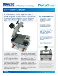
<strong>MKII</strong> <strong>Golden</strong> Gate<br />
<strong>Single</strong> <strong>Reflection</strong> <strong>ATR</strong> <strong>System</strong><br />
<strong>User</strong> Manual<br />
2I-10500 Issue 13
<strong>MKII</strong> <strong>Golden</strong> Gate <strong>Single</strong><br />
<strong>Reflection</strong> <strong>ATR</strong> <strong>System</strong><br />
<strong>User</strong> Manual<br />
2I-10500 Issue 13
<strong>User</strong> Manual<br />
<strong>MKII</strong> <strong>Golden</strong> Gate <strong>Single</strong> <strong>Reflection</strong> <strong>ATR</strong><br />
<strong>System</strong><br />
CONTENTS<br />
1 INTRODUCTION ..................................................................................3<br />
2. UNPACKING AND CHECKLIST .............................................................5<br />
3. TOP PLATES FOR THE <strong>MKII</strong> GOLDEN GATE <strong>ATR</strong>.............................6<br />
4. INSTALLATION.................................................................................15<br />
5. ALIGNMENT ....................................................................................16<br />
6. FITTING ACCESSORIES TO THE <strong>ATR</strong> UNIT ........................................21<br />
7. CHANGING LENSES IN THE <strong>MKII</strong> GOLDEN GATE OPTICAL UNIT......24<br />
8. ANVIL OPTIONS FOR THE <strong>MKII</strong> GOLDEN GATE ..............................27<br />
9. SAMPLING USING THE ACCESSORY ..................................................32<br />
10. LEGEND .......................................................................................41<br />
11 SPARE PARTS FOR <strong>MKII</strong> GOLDEN GATE <strong>ATR</strong>..............................43<br />
12. TECHNICAL SPECIFICATION ...........................................................45<br />
13. INSTALLATION OF THE BENCHMARK BASEPLATE..........................46<br />
© June 2008 <strong>Specac</strong> Ltd. All rights reserved.<br />
<strong>Golden</strong> Gate, Benchmark and Innovative Solutions For Infrared<br />
Spectroscopy are trademarks of <strong>Specac</strong> Ltd. Other product names<br />
mentioned herein may be trademarks of their respective owners.<br />
2
<strong>MKII</strong> <strong>Golden</strong> Gate <strong>Single</strong> <strong>Reflection</strong> <strong>ATR</strong> <strong>System</strong><br />
1 Introduction<br />
Thank you for purchasing a <strong>Specac</strong> Product.<br />
The <strong>MKII</strong> <strong>Golden</strong> Gate <strong>Single</strong> <strong>Reflection</strong> <strong>ATR</strong> system is a versatile<br />
accessory with a number of different sampling options for the<br />
quantitative and qualitative analysis of solids, liquids, pastes and<br />
microsamples.<br />
A complete <strong>Golden</strong> Gate <strong>ATR</strong> system consists of an <strong>ATR</strong> top plate<br />
fixed to an optical beam condensing unit. This is mounted into a<br />
spectrometer using a Benchmark baseplate. Most of the <strong>ATR</strong> top<br />
plates have a special bridge and clamping mechanism giving excellent<br />
and reproducible contact between a solid sample and the single<br />
reflection <strong>ATR</strong> crystal. The different top plates also have a choice of<br />
anvils to provide the best possible contact for different sample forms.<br />
3
<strong>User</strong> Manual<br />
The choice of top plates available for the <strong>Golden</strong> Gate system<br />
includes:<br />
• Diamond crystal 45° top plate P/N 10563.<br />
• Germanium crystal 45° top plate P/N 10566.<br />
• Heated diamond crystal 45° top plate P/N 10540.<br />
• High Temperature Heated diamond 45° top plate P/N 10640.<br />
• Wire holder diamond crystal 45° top plate P/N 10565.<br />
• Microspecular reflectance top plate P/N 10514.<br />
• Reaction cell diamond crystal 45° top plate P/N 10507.<br />
• Low temperature diamond crystal 45° top plate P/N 10590.<br />
• Supercritical fluid diamond crystal 45° top plate P/N 10585.<br />
The optical beam condensing unit of the <strong>Golden</strong> Gate <strong>ATR</strong> consists<br />
of a combination of mirrors and lenses designed to achieve optimal<br />
beam condensation and maximum throughput. The beam condensing<br />
lenses can be made from ZnSe or KRS-5. KRS-5 gives a slightly<br />
wider range for Mid IR studies, though the throughput is slightly lower<br />
than ZnSe.<br />
When pressure is applied the anvil does not rotate against the sample.<br />
This ensures that heat is not generated by friction, as heat could<br />
change the sample. It also ensures that the sample is not displaced<br />
from the correct sampling position.<br />
4
<strong>MKII</strong> <strong>Golden</strong> Gate <strong>Single</strong> <strong>Reflection</strong> <strong>ATR</strong> <strong>System</strong><br />
2. Unpacking and Checklist<br />
The configuration of <strong>Golden</strong> Gate you ordered will determine the<br />
items to check on delivery. (Section 3 of this manual is for the specific<br />
top plates. Please check this section for your appropriate top plate.)<br />
All <strong>Golden</strong> Gate systems will include the following:<br />
• 1 <strong>Golden</strong> Gate optical beam condensing unit with beam<br />
condensing lenses (ZnSe or KRS-5)<br />
• 1 Benchmark baseplate for your FTIR spectrometer<br />
• 1 Ball driver 3.0 mm<br />
• 1 Allen key 2.0 mm<br />
• 2 Purge bellows<br />
Carefully lift your top plate and optical beam condensing unit from the<br />
carry case and place onto a flat bench.<br />
Install the top plate (1) by positioning it on to the optical unit (2) and<br />
clamping down by turning the two thumb screws (3) clockwise.<br />
Important:<br />
The top plate must be fitted the<br />
correct way round. When fitted<br />
correctly the sides of the top<br />
plate will be flush with the<br />
sides of the optical transfer<br />
unit.<br />
1<br />
3<br />
2<br />
Fig 1: Front View of <strong>MKII</strong> <strong>Golden</strong> Gate <strong>ATR</strong> <strong>System</strong><br />
5
<strong>User</strong> Manual<br />
3. Top Plates for the <strong>MKII</strong> <strong>Golden</strong> Gate <strong>ATR</strong><br />
There are a variety of top plates for the <strong>MKII</strong> <strong>Golden</strong> Gate <strong>Single</strong><br />
<strong>Reflection</strong> <strong>ATR</strong>. The top plates can be ordered with a complete<br />
<strong>Golden</strong> Gate system, or separately as upgrades.<br />
<strong>MKII</strong> Diamond <strong>ATR</strong> Top Plate (10563)<br />
Please check on delivery that the following have been included:<br />
• 1 MK II <strong>Golden</strong> Gate Diamond 45° <strong>ATR</strong> Top Plate (Fig 2)<br />
• 1 Sapphire anvil (10531)<br />
• 1 Pellet anvil (10532)<br />
• 1 Volatiles cover (10503)<br />
Fig 2: Angled View of <strong>Golden</strong> Gate Diamond <strong>ATR</strong> Top Plate 10563<br />
Corrosive Samples<br />
The <strong>ATR</strong> element in the <strong>Golden</strong> Gate is high temperature bonded<br />
into tungsten carbide using a metal layer. Tungsten carbide and<br />
diamond have exceptional chemical resistance properties; However,<br />
<strong>Specac</strong> cannot guarantee the support disk or bonding material against<br />
corrosion from all materials, particularly under hostile conditions of<br />
6
<strong>MKII</strong> <strong>Golden</strong> Gate <strong>Single</strong> <strong>Reflection</strong> <strong>ATR</strong> <strong>System</strong><br />
elevated temperature. We recommend that your sample is confined to<br />
the center of the diamond only, if there is a risk of chemical attack<br />
upon contact with the other materials of construction.<br />
A sample spot 2 microns deep with a diameter of 600 microns is<br />
sufficient. We recommend that a pipette, or similar glass capillary tube<br />
is used to apply small sample spots to the center of the diamond only.<br />
The <strong>Golden</strong> Gate is capable of handling a diverse range of chemically<br />
aggressive materials. However, we recommend that in order to protect<br />
your accessory, your sample is cleaned off soon after analysis is<br />
complete.<br />
<strong>MKII</strong> Wire Holder Diamond <strong>ATR</strong> Top Plate (10565)<br />
Please check on delivery that the following have been included:<br />
• 1 <strong>MKII</strong> <strong>Golden</strong> Gate Wire Holder 45° <strong>ATR</strong> top plate (Fig 3)<br />
• 1 Grooved anvil - narrow (10547)<br />
• 1 Grooved anvil - wide (10548)<br />
• 1 Stainless steel anvil (10549)<br />
Fig 3. Angled View of Wire Holder Diamond <strong>ATR</strong> Top Plate 10565<br />
7
<strong>User</strong> Manual<br />
<strong>MKII</strong> Germanium 45° <strong>ATR</strong> Top Plate (10566)<br />
Please check on delivery that the following have been included:<br />
• 1 <strong>MKII</strong> Germanium 45° <strong>ATR</strong> top plate (Fig 4)<br />
• 1 large stainless steel anvil (10567)<br />
• 1 Volatiles cover (10503)<br />
Fig 4: Angled View of Germanium <strong>ATR</strong> Top Plate 10566<br />
Important Note For Use Of Germanium Crystal<br />
The Germanium crystal does not have the same hardness and<br />
chemical resistance as a diamond, and should be treated accordingly.<br />
Be careful not to put a point loading on the crystal, particularly with<br />
hard or abrasive samples. With samples such as rubber and soft<br />
polymers covering the crystal, normal anvil pressures may be used.<br />
Check on the chemical resistance before potentially damaging<br />
materials are brought into contact with the crystal. Thin films on plastic<br />
substrates can be analyzed, but take care if the substrate is metallic.<br />
A good idea is to apply pressure gradually, taking scans to see if the<br />
spectra are acceptable.<br />
8
<strong>MKII</strong> <strong>Golden</strong> Gate <strong>Single</strong> <strong>Reflection</strong> <strong>ATR</strong> <strong>System</strong><br />
<strong>MKII</strong> Heated Diamond <strong>ATR</strong> Top Plate (10540 and 10542)<br />
Please check on delivery that the following have been included:<br />
• 1 <strong>MKII</strong> Heated Diamond 45° <strong>ATR</strong> Top Plate (Fig 5)<br />
• 1 4000 Series Temperature Controller for the heated top plate<br />
• 1 Sapphire anvil (10531)<br />
• 1 Pellet anvil (10532)<br />
• 1 Volatiles cover (10503)<br />
Fig 5: Angled View of Heated Diamond <strong>ATR</strong> Top Plate 10540<br />
The heated top plate can be used up to 200°C. A separate manual for<br />
the 4000 Series temperature controller is included with this top plate<br />
option.<br />
Warning: The diamond mounting plate in the heated top plate has a<br />
very small air gap around its edge. This minimizes heat loss to the<br />
surrounding top plate and ensures quick warm up. If excessive<br />
amounts of solvent are used to clean the diamond it is possible for it to<br />
leak past the diamond plate, giving solvent absorption bands and<br />
softening the adhesive. For this reason, the diamond should only be<br />
cleaned using a tissue moistened with solvent.<br />
9
<strong>User</strong> Manual<br />
<strong>MKII</strong> High Temperature Heated Diamond <strong>ATR</strong> Top Plate (10640<br />
and 10642)<br />
Please check on delivery that the following have been included:<br />
• 1 <strong>MKII</strong> High Temperature Heated Diamond 45° <strong>ATR</strong> Top Plate (Fig<br />
5)<br />
• 1 4000 Series Temperature Controller for the heated top plate<br />
• 1 Sapphire anvil (10531)<br />
• 1 Pellet anvil (10532)<br />
• 1 Volatiles cover (10503)<br />
The heated top plate can be used up to 300°C. A separate manual for<br />
the 4000 Series temperature controller is included with this top plate<br />
option.<br />
Note: The diamond <strong>ATR</strong> crystal and tungsten carbide support puck in<br />
the high temperature heated top plate does not have a small air<br />
gap around its edge. The item is sealed around the edge and so<br />
protects from the ingress of liquid samples or volatile solvent<br />
vapours into the optical unit below.<br />
10<br />
Fig 5: Angled View of High Temperature Heated Diamond <strong>ATR</strong> Top<br />
Plate 10640
<strong>MKII</strong> <strong>Golden</strong> Gate <strong>Single</strong> <strong>Reflection</strong> <strong>ATR</strong> <strong>System</strong><br />
Microspecular <strong>Reflection</strong> Top Plate (10514)<br />
This top plate can be fitted to the <strong>Golden</strong> Gate optical unit to provide<br />
a single reflection 45° specular reflectance measurement of<br />
microsamples. The top plate slot aperture is 5 mm x 2.5 mm.<br />
Please check on delivery that the following have been included:<br />
• 1 Microspecular reflection top plate (Fig 6)<br />
• 1 Reference mirror<br />
Fig 6: Angled View of Microspecular <strong>Reflection</strong> Top Plate 10514<br />
Reaction Cell Diamond <strong>ATR</strong> Top Plate (10507)<br />
This is a specialist top plate that incorporates a 45° diamond crystal<br />
within a reaction chamber. It is capable of operating at temperatures<br />
up to 200°C and at up to 3000 psi pressure.<br />
A special manual and controlling system is provided for this <strong>Golden</strong><br />
Gate top plate option. There is also an additional stirring mechanism<br />
(P/N 10513) in an alternative top pressure plate assembly that can be<br />
used with the reaction chamber. (See Fig 7).<br />
11
<strong>User</strong> Manual<br />
<strong>Golden</strong> Gate Reaction<br />
Cell Pressure Cap Stirring<br />
Mechanism 10513<br />
<strong>Golden</strong> Gate Reaction<br />
Cell Top Plate Assembly<br />
10507<br />
12<br />
Fig 7: Angled View of Reaction Cell Top Plate Without Stirring Mechanism
<strong>MKII</strong> <strong>Golden</strong> Gate <strong>Single</strong> <strong>Reflection</strong> <strong>ATR</strong> <strong>System</strong><br />
Low Temperature Diamond 45° <strong>ATR</strong> Top Plate (10590 and 10592)<br />
Please check on delivery that the following have been included:<br />
• 1 Low Temperature Diamond 45° <strong>ATR</strong> Top Plate (Fig 8)<br />
• 1 4000 Series Temperature Controller for the Low Temperature<br />
Diamond <strong>ATR</strong> Top Plate<br />
• Sapphire tipped solids anvil<br />
• Liquid sample injector (insulated hypodermic needle and glass<br />
syringe)<br />
• Plastic funnel<br />
• Long T-bar Allen key (5 mm)<br />
• Allen Key (3 mm)<br />
• Glass filled PTFE gaskets (5)<br />
• High thermal transfer gaskets (20)<br />
• Spare Viton o-ring<br />
• Manual for operation of Low Temperature <strong>Golden</strong> Gate<br />
Fig 8: Angled View of <strong>MKII</strong> Low Temperature Diamond <strong>ATR</strong> Top Plate 10590<br />
The Low Temperature Diamond 45° <strong>ATR</strong> Top Plate operates over a<br />
temperature range of -150°C to + 80°C.<br />
13
<strong>User</strong> Manual<br />
Supercritical Fluid Diamond <strong>ATR</strong> Top Plate (10585 and 10586)<br />
Please check on delivery that the following have been included:<br />
• 1 Supercritical Fluid Diamond <strong>ATR</strong> Top Plate (Fig 9)<br />
• 1 4000 Series Temperature Controller for the Supercritical Fluid<br />
Diamond <strong>ATR</strong> Top Plate<br />
• Manual for SCF Top Plate operation<br />
• Open Ended Spanner 1/4” – 5/16 ” (2 off)<br />
• Torque wrench (10504)<br />
• Socket drive 2.5 mm A/F<br />
• Gaskets (10)<br />
Fig 9: Angled View of Supercritical Fluid Diamond <strong>ATR</strong> Top Plate 10585<br />
The Supercritical Fluid Diamond <strong>ATR</strong> Top Plate is specified to operate<br />
at pressures up to 6000 psi and temperatures up to 300°C. A separate<br />
manual for the temperature controller is included with this top plate<br />
option.<br />
14
<strong>MKII</strong> <strong>Golden</strong> Gate <strong>Single</strong> <strong>Reflection</strong> <strong>ATR</strong> <strong>System</strong><br />
4. Installation<br />
The <strong>MKII</strong> <strong>Golden</strong> Gate <strong>Single</strong> <strong>Reflection</strong> <strong>ATR</strong> is supported on a<br />
Benchmark baseplate when installed into a spectrometer. The<br />
baseplate has three support pillars (one flat one and two at the front<br />
with location pins) and a fourth front central pillar into which the fixing<br />
thumb screw (4) is tightened.<br />
Note:<br />
It is best to install the Benchmark baseplate in the<br />
spectrometer first, before locating the <strong>Golden</strong> Gate<br />
<strong>ATR</strong> accessory.<br />
Fixing holes and studs in the baseplate will vary dependant on the<br />
make and model of your spectrometer. For details on how to install<br />
your baseplate and <strong>ATR</strong> accessory in the spectrometer refer to the<br />
relevant section of the Accessory Installation Guide (see section13).<br />
4<br />
Fig 10: <strong>Golden</strong> Gate <strong>ATR</strong> Top Plate on <strong>Golden</strong> Gate Optical Unit<br />
15
<strong>User</strong> Manual<br />
5. Alignment<br />
When you have installed the <strong>MKII</strong> <strong>Golden</strong> Gate <strong>Single</strong> <strong>Reflection</strong><br />
<strong>ATR</strong> and top plate into your spectrometer please check the alignment<br />
of the accessory.<br />
The <strong>Golden</strong> Gate <strong>ATR</strong> is given a preliminary alignment in the<br />
factory. On installation some transmitted energy will be recorded by the<br />
spectrometer, but for best results adjusting the accessory optics will<br />
maximize the optical throughput.<br />
Note:<br />
The throughput varies with spectrometer design<br />
features such as ‘F’ number, ‘J’ stop etc., but should<br />
typically be 6% or more when compared with an open<br />
beam. It is important with all accessories, that the<br />
maximum throughput is achieved. This ensures<br />
optimum analytical performance and signal-to-noise<br />
ratio.<br />
The beam condensing optics unit has six optical components. Two<br />
mirrors and one lens make up the input system. An identical set of<br />
mirrors and lens form the output system (see Fig 11). Two mirrors (M1<br />
and M4) are fixed while the two larger mirrors (M2 and M3) have<br />
rotation and tilt adjustments. The focusing lenses (L1 and L2) are<br />
adjustable for focus by moving up and down in their supports.<br />
The beam path diagram shows a Diamond <strong>ATR</strong> top plate in position,<br />
but the principles for alignment are the same for any other top plate.<br />
When aligning the Microspecular top plate, its own reference mirror<br />
must be placed over the sampling aperture.<br />
It is always best to start alignment from the output mirror (the one<br />
nearest the detector).<br />
Note: In these instructions it is assumed M4 is the output mirror. If<br />
your output mirror is M1 follow the instructions taking the optical<br />
components in the reverse order to that shown in Fig 11.<br />
16
<strong>MKII</strong> <strong>Golden</strong> Gate <strong>Single</strong> <strong>Reflection</strong> <strong>ATR</strong> <strong>System</strong><br />
L1 Sample L2<br />
M2<br />
M3<br />
M1<br />
M4<br />
Fig 11: Optical Beam Path of <strong>Golden</strong> Gate <strong>ATR</strong> <strong>System</strong><br />
To adjust the alignment of the <strong>MKII</strong> <strong>Golden</strong> Gate:<br />
1. Loosen the two thumb screws (5) and remove the front cover (6) to<br />
reveal the optics (See Figs 12 and 13). The diamond top plate has<br />
been removed from Fig 13 for clarity.<br />
6<br />
5<br />
Fig 12: Optics Cover Removal from <strong>Golden</strong> Gate <strong>ATR</strong> <strong>System</strong><br />
17
<strong>User</strong> Manual<br />
13<br />
11<br />
12<br />
14<br />
10<br />
8<br />
9<br />
7<br />
Fig 13: View of Optical Components in the <strong>Golden</strong> Gate <strong>ATR</strong> <strong>System</strong><br />
2. The double mirror mount (7) is fixed. The input side mirror (M1)<br />
ensures that the beam is correctly directed to mirror (M2). In the<br />
same way the output mirror (M4) needs no adjustment.<br />
3. Where the spectrometer allows the accessory to be moved left to<br />
right, move the <strong>ATR</strong> unit to find the best position where the<br />
transmission is at a maximum and firmly secure the base-plate. (In<br />
some spectrometers it may be necessary to remove the optical unit<br />
before securing the base-plate. Where this is the case, ensure that<br />
the baseplate does not move when removing the optical unit).<br />
4. Using the large Allen key in screw (8) of mirror M3 very gently<br />
adjust the rotational movement of the mirror to achieve maximum<br />
energy.<br />
18
<strong>MKII</strong> <strong>Golden</strong> Gate <strong>Single</strong> <strong>Reflection</strong> <strong>ATR</strong> <strong>System</strong><br />
Tip:<br />
If the energy reading on the instrument monitor goes to<br />
zero while making any of the adjustments always bring it<br />
back with the same adjustment before proceeding further.<br />
5. Adjust mirror M3 tilt position by inserting the smaller Allen key into<br />
screw (9) and turning to maximize the energy.<br />
Important : Turning the Allen key too far anticlockwise will cause<br />
the screw to dislodge from the back of the mirror (10).<br />
If this accidentally happens, turn the Allen key a full<br />
circle in the same direction to dislodge the screw<br />
further and free it. (Do not remove it). Next, push the<br />
spring mounted mirror (10) away from the black<br />
anodized mirror mount and turn the Allen key<br />
clockwise until the screw (9) is re-set against the rear<br />
of the spring<br />
.<br />
6. The lens focus is adjusted by slightly loosening the locking screw<br />
(11) in lens L2. A spring washer ensures there is some friction to<br />
hold the lens barrel.<br />
Hold on to the lens by the tiller bar (12) whilst loosening the locking<br />
screw (11) to prevent the lens barrel (13) from sliding down the<br />
outer casing (14). Wriggle the tiller bar (12) gently to move the lens<br />
barrel assembly up or down to maximize the energy.<br />
7. Tighten the locking screw (11) to secure the lens in the optimum<br />
position.<br />
8. Maximize the energy by adjusting the rotation and tilt movement of<br />
mirror M2, in the same way as M3 (steps 4 and 5).<br />
9. Complete the alignment procedure by adjusting the lens L1, in the<br />
same way as L2 (steps 6 and 7).<br />
10. Repeat the rotation, tilt and focus adjustments as in steps 4 to 9<br />
until maximum energy throughput is achieved and then replace the<br />
front cover plate (6).<br />
19
<strong>User</strong> Manual<br />
Corrosive Samples<br />
The diamond <strong>ATR</strong> element in the <strong>Golden</strong> Gate is high temperature<br />
bonded into tungsten carbide using a metal layer. Tungsten carbide<br />
and diamond have exceptional chemical resistance properties;<br />
However, <strong>Specac</strong> cannot guarantee the support disk or bonding<br />
material against corrosion from all materials, particularly under hostile<br />
conditions of elevated temperature.<br />
We recommend that your sample is confined to the center of the<br />
diamond only, if there is a risk of chemical attack upon contact with the<br />
other materials of construction.<br />
A sample spot 2 microns deep with a diameter of 600 microns is<br />
sufficient. We recommend that a pipette, or similar glass capillary tube,<br />
is used to apply small sample spots to the center of the diamond only.<br />
The <strong>Golden</strong> Gate is capable of handling a diverse range of<br />
chemically aggressive materials. However, we recommend that in<br />
order to protect your accessory, your sample is cleaned off soon after<br />
analysis is complete.<br />
20
<strong>MKII</strong> <strong>Golden</strong> Gate <strong>Single</strong> <strong>Reflection</strong> <strong>ATR</strong> <strong>System</strong><br />
6. Fitting Accessories to the <strong>ATR</strong> Unit<br />
When the <strong>MKII</strong> <strong>Golden</strong> Gate <strong>Single</strong> <strong>Reflection</strong> <strong>ATR</strong> has been<br />
installed and aligned in the spectrometer you have the options of fitting<br />
a polarizer and/or purging the <strong>ATR</strong> accessory.<br />
Fitting a Polarizer<br />
The standard <strong>Specac</strong> polarizers (12000 Series) can be fitted to the<br />
apertures (15) of the <strong>ATR</strong>. The polarizers push fit in these apertures<br />
and can be rotated to the desired orientation. The polarizer will<br />
transmit at a maximum (perpendicular component of the polarized<br />
light) when it is mounted so that the notch slot in the polarizer holder<br />
ring is in the vertical plane. Fitting the polarizer to either aperture of the<br />
<strong>ATR</strong> will have the same effect.<br />
There is also a special Benchmark Rotatable Polarizer Mount<br />
Assembly (including polarizer) P/N 12510 that fits directly to the<br />
aperture ports of all Benchmark baseplate compatible optical units<br />
such as found on the <strong>Golden</strong> Gate <strong>ATR</strong> accessory. (Please ask<br />
<strong>Specac</strong> for details).<br />
15<br />
4<br />
16<br />
Fig 14: Purge Features of the <strong>MKII</strong> <strong>Golden</strong> Gate <strong>ATR</strong> <strong>System</strong><br />
Note: Fit a polarizer where required before purging the system.<br />
21
<strong>User</strong> Manual<br />
Purging the <strong>System</strong><br />
The <strong>MKII</strong> <strong>Golden</strong> Gate <strong>ATR</strong> optical unit is fitted with purge ports<br />
(16). The protective rubber sealing covers are removed from the purge<br />
ports and purge tubing can be connected. To allow the system to be<br />
purged efficiently it is necessary to fit the flexible purge bellows (17).<br />
Tip:<br />
It is recommended that purge bellows are fitted during<br />
use to help stabilize the instrument background, even<br />
if the accessory is not being purged.<br />
Fitting the Purge Bellows (P/N 10707)<br />
1. With the Benchmark base-plate secured, and <strong>Golden</strong> Gate<br />
installed, measure the approximate lengths between the<br />
spectrometer side walls and the flat end of the <strong>ATR</strong> unit<br />
(Dimension ‘X’ – see Fig 15).<br />
2. Using a sharp razor, cut lengths of the flexible purge tube which<br />
are equivalent to the measured length (X) plus an additional<br />
10 mm for each.<br />
17<br />
Length “X”<br />
22<br />
Fig 15: Fitting Purge Bellows to the <strong>MKII</strong> <strong>Golden</strong> Gate <strong>ATR</strong> <strong>System</strong>
<strong>MKII</strong> <strong>Golden</strong> Gate <strong>Single</strong> <strong>Reflection</strong> <strong>ATR</strong> <strong>System</strong><br />
Tip:<br />
It is easier to cut the purge tube between the hard<br />
ridges.<br />
3. Unscrew the fixing thumb screw (4) and remove the <strong>Golden</strong><br />
Gate <strong>ATR</strong> Accessory from the sample compartment.<br />
Note:<br />
Fit a 12000 Series polarizer at this stage if required.<br />
4. Fit the flexible purge bellows over both end apertures as seen at<br />
Fig 15 and compress sufficiently to enable the assembly to fit into<br />
the spectrometer.<br />
5. Ensure the bellows are not obstructing the beam and then tighten<br />
the accessory fixing thumb screw (4) to secure the <strong>Golden</strong> Gate<br />
<strong>ATR</strong> optical unit back onto the Benchmark base-plate.<br />
23
<strong>User</strong> Manual<br />
7. Changing Lenses in the <strong>MKII</strong> <strong>Golden</strong> Gate<br />
Optical Unit<br />
The <strong>MKII</strong> <strong>Golden</strong> Gate <strong>ATR</strong> accessory is provided with ZnSe or<br />
KRS-5 beam condensing lenses. If you wish to change from one set of<br />
lenses to the other they are available as upgrade kits.<br />
10552 ZnSe Lens (2) Upgrade Kit<br />
10508 KRS-5 Lens (2) Upgrade Kit<br />
Removing Lenses<br />
1. The front cover (6) of the optical unit is removed by loosening the<br />
thumb screws (5) to gain access to the optics.<br />
L1<br />
L2<br />
12<br />
14<br />
11<br />
Fig 16: Changing the Lens Assemblies in a <strong>MKII</strong> <strong>Golden</strong> Gate <strong>ATR</strong> <strong>System</strong><br />
24
<strong>MKII</strong> <strong>Golden</strong> Gate <strong>Single</strong> <strong>Reflection</strong> <strong>ATR</strong> <strong>System</strong><br />
2. Any <strong>Golden</strong> Gate <strong>ATR</strong> Top Plate being used must be removed<br />
from the optical unit. This is achieved by loosening the two thumb<br />
screws (3) on the Top Plate and lifting it up and away from the<br />
optical unit.<br />
3. The lens assemblies in the optical unit are moved by the tiller bars<br />
(12) (see Fig 16). Remove the tiller bars from the lens barrels by<br />
unscrewing anticlockwise.<br />
4. Loosen the locking screw (11) making the lens barrel free to move<br />
in the outer casing (14).<br />
5. Carefully remove both lens assemblies by pulling up and out of<br />
their casings, through the top of the optical unit.<br />
Fitting New Lenses<br />
To fit new lenses the procedure for removal is reversed.<br />
1. Carefully slide the new lenses into the casings through the top of<br />
the <strong>Golden</strong> Gate <strong>ATR</strong> optical unit.<br />
L1<br />
L2<br />
Fig 17: Simplified diagram showing position of lens assemblies L1 and L2 in the<br />
<strong>MKII</strong> <strong>Golden</strong> Gate <strong>ATR</strong> <strong>System</strong>. (Note that an <strong>ATR</strong> Top Plate is also shown in<br />
position on top of the optical unit)<br />
25
<strong>User</strong> Manual<br />
Important:<br />
Ensure the holes in the lens barrels that the tiller bars<br />
(12) screw into are aligned with the front slots in the<br />
casings (14).<br />
2. Tighten the tiller bars (12) into their holes in the lens barrels (turn<br />
clockwise).<br />
3. Adjust the position of the new lenses so that they are<br />
approximately midway in their casings and tighten the locking<br />
screw (11). See the simple diagram Fig 17 to help indicate<br />
approximately where the lens should be positioned and how close<br />
they will be to the underside of the <strong>Golden</strong> Gate <strong>ATR</strong> Top Plate<br />
when it is in position on the optical unit.<br />
4. The <strong>Golden</strong> Gate accessory will now need realignment. Follow the<br />
instructions for alignment at Section 5 of this manual.<br />
26
<strong>MKII</strong> <strong>Golden</strong> Gate <strong>Single</strong> <strong>Reflection</strong> <strong>ATR</strong> <strong>System</strong><br />
8. Anvil Options for the <strong>MKII</strong> <strong>Golden</strong> Gate<br />
Choice of Anvils and their Uses<br />
There are many different compression head anvils that can be used<br />
with the <strong>Golden</strong> Gate <strong>Single</strong> <strong>Reflection</strong> <strong>ATR</strong> top plates. The types and<br />
their uses are shown in the following table:-<br />
Anvil P/N Description Sample Type Use Top Plate Use<br />
10531 Sapphire Solids and<br />
Powders<br />
All diamond<br />
plates<br />
10532 Pellet Polymer Beads All diamond<br />
plates<br />
10536 Reactive sample Air Sensitive<br />
Samples<br />
All diamond<br />
plates<br />
10547 Grooved narrow Fibers/Wires Diamond wire<br />
holder<br />
10548 Grooved wide Fibers/Wires Diamond wire<br />
holder<br />
10549 Stainless steel flat Solids and<br />
Powders<br />
10567 Large stainless<br />
steel flat<br />
10568 Micro reaction<br />
flow cell<br />
10569 View thru<br />
anvil/bridge<br />
assembly<br />
Solids and<br />
Powders<br />
Liquids/Supercritic<br />
al fluids<br />
Solids, Powders<br />
and Fibers<br />
All diamond<br />
plates<br />
Germanium top<br />
plate<br />
All diamond<br />
plates<br />
All top plates<br />
27
<strong>User</strong> Manual<br />
Sapphire Anvil (10531- Fig 18a)<br />
This anvil can be used with all diamond <strong>ATR</strong> top plates, for solid or<br />
powder samples. The sapphire element on the anvil face is 3.8 mm in<br />
diameter.<br />
Pellet Anvil (10532 - Fig 19)<br />
Fig 18a<br />
This anvil is made of stainless steel and has a concave recess<br />
designed for round samples such as polymer pellets. It can be used on<br />
all diamond <strong>ATR</strong> top plates and, if the sample is relatively soft, with a<br />
Germanium top plate.<br />
Fig 19<br />
Grooved Anvils Narrow (10547) - Wide (10548)<br />
(Figs 20a & 20b)<br />
These anvils are made of stainless steel and have a groove cut<br />
through the pressing face to position fibers or thin wires in the center of<br />
28
<strong>MKII</strong> <strong>Golden</strong> Gate <strong>Single</strong> <strong>Reflection</strong> <strong>ATR</strong> <strong>System</strong><br />
the <strong>ATR</strong> crystal. These anvils can be used on all diamond <strong>ATR</strong> plates<br />
and are supplied as standard with the wire holder top plate.<br />
Fig 20a<br />
Fig 20b<br />
Stainless Steel Anvils (10549 and 10567 Figs 21a & 21b)<br />
These anvils can be used in place of the sapphire flat anvils if desired.<br />
The large stainless steel anvil (10567) should always be used with the<br />
germanium top plate, (it is the anvil supplied with this top plate).<br />
Fig 21a<br />
Reactive Sample Anvil (10536 - Fig 22)<br />
Fig 21b<br />
This is a sapphire anvil with an Isolast O-ring around the outer edge.<br />
When clamped in position an air tight seal is formed around the sample<br />
being held in contact against the <strong>ATR</strong> crystal. Air sensitive samples<br />
can be positioned on a top plate in a controlled<br />
environment (for example a glove box or fume<br />
cupboard). The top plate and anvil can then be<br />
taken from the controlled area and placed on<br />
the <strong>Golden</strong> Gate optical unit in the<br />
spectrometer. This anvil can be used on all<br />
diamond <strong>ATR</strong> top plates and, if the sample is<br />
relatively soft, with the germanium top plate.<br />
Fig 22<br />
29
<strong>User</strong> Manual<br />
Micro Reaction Flow Cell Anvil (10568 - Fig 23)<br />
This anvil is made of stainless steel and has 1/16” flow tubes to allow<br />
liquids to flow across the <strong>ATR</strong> crystal. It can be used at pressures up to<br />
1000 psi and temperatures up to 300°C. The internal volume of the cell<br />
is 28 microlitres. The micro reaction flow cell can be clamped for use<br />
with all diamond <strong>ATR</strong> plates.<br />
There is also a special “static” (non-flow) version of this anvil which has<br />
Luer ports and PTFE plug fittings in place of the standard 1/16”<br />
stainless steel flow pipe fittings. Please contact <strong>Specac</strong> for more<br />
details.<br />
Fig 23<br />
View Thru Anvil/Bridge Assembly (10569 - Figs 24a & 24b)<br />
This is a special anvil allowing you to see the sample compressing<br />
onto the <strong>ATR</strong> crystal. The sapphire anvil face doubles as a viewing<br />
port. The anvil moves up and down in the clamp bridge by rotation of<br />
the viewing lens assembly. This bridge/anvil combination can be used<br />
on all <strong>ATR</strong> top plates, diamond and germanium. The clamp bridge and<br />
torque limiter mechanism of the standard <strong>ATR</strong> top plates must be<br />
replaced by the specific bridge and view thru anvil assembly. This is<br />
achieved simply by undoing the hinge screw from the bridge pivot hole<br />
and removing the standard clamp/bridge assembly.<br />
30
<strong>MKII</strong> <strong>Golden</strong> Gate <strong>Single</strong> <strong>Reflection</strong> <strong>ATR</strong> <strong>System</strong><br />
Fig 24: Side View of View-Thru Anvil Bridge Assembly<br />
Important :<br />
Note :<br />
When removing the bridge mechanism and replacing<br />
with the view thru bridge it is important the stay up<br />
catch pin inside the bridge does not fall out of position.<br />
If it does fall out just replace.<br />
The View-Thru Anvil Bridge Assembly must not be<br />
used with the High Temperature Heated <strong>Golden</strong><br />
Gate Top Plate P/N GS10640 because of the<br />
sample temperatures that this accessory can generate.<br />
31
<strong>User</strong> Manual<br />
9. Sampling using the Accessory<br />
General Principles<br />
When using the <strong>MKII</strong> <strong>Golden</strong> Gate <strong>Single</strong> <strong>Reflection</strong> <strong>ATR</strong> accessory<br />
the sample is placed onto the crystal area (18) of the top plate. The<br />
contact between sample and crystal is improved using the clamp<br />
bridge (19) and an appropriate compression head anvil (20).<br />
For diamond top plates, the diamond crystal is brazed into a<br />
surrounding support disc of tungsten carbide.The germanium top plate<br />
has a germanium crystal glued into a stainless steel support disk.<br />
(Specific details for all top plate options can be found in Section 3 of<br />
this manual.)<br />
The diamond <strong>ATR</strong> top plate is used to illustrate sampling in this<br />
manual. If using a germanium top plate the stainless steel flat anvil<br />
compression head (10567) should be used, where the sapphire anvil<br />
(10531) has been shown for the diamond top plate.<br />
21<br />
20<br />
19<br />
23<br />
18<br />
32<br />
Fig 25: Front View of <strong>MKII</strong> Diamond <strong>ATR</strong> Top Plate (Bridge Closed)
<strong>MKII</strong> <strong>Golden</strong> Gate <strong>Single</strong> <strong>Reflection</strong> <strong>ATR</strong> <strong>System</strong><br />
22<br />
21<br />
23<br />
20<br />
25<br />
24<br />
Fig 26: Angled View of <strong>MKII</strong> Diamond <strong>ATR</strong> Top Plate (Bridge Open)<br />
Features of the <strong>MKII</strong> <strong>Golden</strong> Gate Clamp Bridge<br />
Torque Limiter Screw<br />
The <strong>MKII</strong> <strong>Golden</strong> Gate <strong>Single</strong> <strong>Reflection</strong> <strong>ATR</strong> top plates are<br />
provided with a special built in torque limiter screw (21). When the<br />
torque limiter screw (21) is turned clockwise it will provide a maximum<br />
load of 80lbs (spread over the area of the anvil face) to the sample.<br />
After this load has been achieved the<br />
22<br />
screw rotates without increasing the<br />
load. This means that there is no need to<br />
use a torque wrench for routine<br />
sampling. However, a torque wrench<br />
with torx head adaptor (10504 and<br />
10505 respectively) can be supplied<br />
separately to provide loads up to 160lbs,<br />
using the central torx head screw fixing<br />
(22). (See Fig 27).<br />
Figure 27: Torque limiter screw showing torx screw fixing<br />
33
<strong>User</strong> Manual<br />
Quick Lock and Release Mechanism<br />
The clamp bridge (19) has a quick lock and release mechanism (23).<br />
When pressure needs to be applied to a solid sample the bridge must<br />
be closed (see Fig 25). The quick lock and release screw is pushed<br />
down and turned clockwise 90° to lock the bridge closed. To release<br />
the bridge the screw is pushed down and turned anticlockwise 90°.<br />
Important :<br />
When closing the clamp bridge ensure that the anvil<br />
is retracted so that it will not crash down on the<br />
crystal or sample.<br />
Stay up Device<br />
At the hinge point of the <strong>Golden</strong> Gate clamp there is a spring ball<br />
bearing device (24) that prevents an open bridge from accidentally<br />
falling back down to its closed position on the bridge support (25).<br />
When sampling liquids there is no need to use the bridge as the<br />
sample will be in intimate contact with the crystal. This device allows<br />
the bridge to stay open for convenience when sampling liquids (see Fig<br />
26).<br />
Preparing the Accessory for Analysis<br />
For the Diamond <strong>ATR</strong> the active sampling area is about 1.0 mm<br />
diameter, in the center of the diamond. Samples smaller than this<br />
should be placed centrally on the diamond for optimum results.<br />
9.1 Undo the bridge quick lock screw (23) and lift the clamp bridge<br />
(19) up past the stay up catch (24). The anvil (20) does not have<br />
to be in contact with the diamond (18) crystal face to record a<br />
background spectrum.<br />
9.2 Ensure the diamond is clean and record a background spectrum.<br />
Note: If it is necessary to clamp the Sapphire Anvil (20) (10531 or<br />
10522) directly onto the diamond without a sample, (e.g. to<br />
34
<strong>MKII</strong> <strong>Golden</strong> Gate <strong>Single</strong> <strong>Reflection</strong> <strong>ATR</strong> <strong>System</strong><br />
check for contamination) care should be taken to ensure that<br />
the anvil is level to the diamond crystal. This can be done by<br />
rotating the anvil (20) slightly before applying pressure. Only a<br />
small amount of pressure should be needed to check for<br />
contamination. It is not advisable to apply the maximum<br />
pressure loading without a sample.<br />
21<br />
26<br />
23<br />
19<br />
20<br />
18<br />
25<br />
Fig 28: Closed Bridge <strong>MKII</strong> <strong>Golden</strong> Gate Diamond <strong>ATR</strong> Top Plate<br />
Using for Different Sample Types<br />
Important: <strong>Golden</strong> Gate elements are selected for their freedom<br />
from natural structural flaws using optical test methods. It<br />
is possible to over-stress the diamond element by applying<br />
excessive point loads at the extreme corners.<br />
If you suspect that your sample may contain exceptionally<br />
hard particles, ensure that only a small amount of sample is<br />
used and is placed centrally on the diamond. Do not apply<br />
maximum loading immediately. Use a torque wrench set<br />
to 20 cNm (approx 33 lbs). Acceptable spectra may be<br />
obtained without the requirement for the full load of 100<br />
cNm (160 lbs).<br />
35
<strong>User</strong> Manual<br />
Powders<br />
1. Prepare the accessory for analysis by collecting a background<br />
spectrum. (See 9.1 to 9.2, page 33).<br />
2. Ensure the sapphire anvil (20) is firmly fitted to the end of the<br />
sample screw clamp (26) by pushing the hollow end over the<br />
retaining ‘0’ ring. Position the anvil to be parallel to the bridge.<br />
Note:<br />
When fitted, some movement of the sample<br />
compression head (20) is allowed to adjust to the<br />
sample shape during compression. This movement<br />
enables even pressure to be applied across the<br />
contact area.<br />
3. Apply the powder to the surface of the diamond (18).<br />
4. Gently clamp down the bridge (19) using the bridge quick lock<br />
screw (23), ensuring that the anvil is clear of the sample.<br />
5. Screw down the anvil (20) via the torque limiter screw (21). When<br />
a load of 80lbs is achieved the screw will rotate freely. The sample<br />
is now compressed between the diamond and sapphire anvil.<br />
Record the spectrum of the sample.<br />
6. To remove or change the sample, release the pressure on the<br />
sample by first unscrewing the torque limiter screw (21) before<br />
undoing the bridge quick lock thumb screw (23). Rest the bridge<br />
up past the stay up catch (24).<br />
7. Clean the powder from the diamond and wipe any powder off the<br />
sapphire anvil (20) of the compression head.<br />
Flat Solid Samples<br />
Flat solid samples are analyzed in the same way as powders, placing<br />
the sample face down on the diamond.<br />
36
<strong>MKII</strong> <strong>Golden</strong> Gate <strong>Single</strong> <strong>Reflection</strong> <strong>ATR</strong> <strong>System</strong><br />
Pellets<br />
Pellets are analyzed in the same way as powders, except that the<br />
pellet anvil is used. The pellet should be placed centrally on the<br />
diamond.<br />
Ensure the conical recessed stainless steel pellet anvil (10532) (20) is<br />
firmly fitted to the end of the sample screw clamp (26) by pushing the<br />
hollow end over the retaining ‘0’ ring.<br />
Notes:<br />
The conical recess head ensures that the sample is<br />
retained safely under the anvil during compression.<br />
Pellets of 1.5mm in diameter or less are not suitable<br />
for the recessed head. These are best analyzed with<br />
careful manipulation using the flat sapphire anvil.<br />
Fibers<br />
Fibers are analyzed in the same way as powders. Lay the fiber<br />
centrally across the diamond crystal surface and tape down the ends<br />
out side the diamond crystal surface if necessary.<br />
Note:<br />
The fiber may be taped across a support frame and<br />
laid on the <strong>ATR</strong> top-plate with the sample centrally<br />
across the diamond. For larger wires or fibers the Wire<br />
Holder diamond <strong>ATR</strong> Top Plate (10565) can be used<br />
with an appropriate narrow or wide Grooved Anvil<br />
(10547) or (10548).<br />
37
<strong>User</strong> Manual<br />
Liquids and Pastes<br />
1. Prepare the accessory for analysis. (See 9.1 to 9.2, page 33)<br />
Note:<br />
There is no need to use an anvil and the bridge clamp.<br />
The bridge can remain open past the stay up catch<br />
(24). (See as Fig 26).<br />
2. Apply a small quantity of the sample, sufficient to cover the<br />
diamond surface (only a thin covering is required).<br />
3. If the liquid is volatile place the volatiles cover 10503 (Fig 29) over<br />
the sample to prevent evaporation.<br />
4. Record the spectrum of the sample .<br />
5. To remove the sample wipe the diamond and tungsten carbide<br />
surface with a cloth and suitable solvent.<br />
Fig 29: Volatiles Cover (10503)<br />
Corrosive Samples<br />
The diamond <strong>ATR</strong> element in the <strong>Golden</strong> Gate is high temperature<br />
bonded into tungsten carbide using a metal layer. Tungsten carbide<br />
and diamond have exceptional chemical resistance properties;<br />
However, <strong>Specac</strong> cannot guarantee the support disk or bonding<br />
material against corrosion from all materials, particularly under hostile<br />
conditions of elevated temperature.<br />
38
<strong>MKII</strong> <strong>Golden</strong> Gate <strong>Single</strong> <strong>Reflection</strong> <strong>ATR</strong> <strong>System</strong><br />
We recommend that your sample is confined to the center of the<br />
diamond only, if there is a risk of chemical attack upon contact with the<br />
other materials of construction.<br />
A sample spot 2 microns deep with a diameter of 600 microns is<br />
sufficient. We recommend that a pipette, or similar glass capillary<br />
tube, is used to apply small sample spots to the center of the diamond<br />
only.<br />
The <strong>Golden</strong> Gate is capable of handling a diverse range of<br />
chemically aggressive materials. However, we recommend that in<br />
order to protect your accessory, your sample is cleaned off soon after<br />
analysis is complete.<br />
Pressure on Sample (Load)<br />
The table on page 39 gives a guide to recommended loads for different<br />
sample types. The optimum load requirements for some typical<br />
samples are determined by recording spectra at increasing loads until<br />
the desired result is obtained. The optional Torque Wrench (10504)<br />
with Torx Adapter (10505), not supplied with the <strong>MKII</strong> <strong>Golden</strong> Gate,<br />
should be used for these settings (see Fig 30).<br />
Optional Torque Wrench<br />
There is a torx screw fixing (22) inside the<br />
top of the torque limiter screw (21). The torx<br />
head adapter piece of the torque wrench fits<br />
in to this torx screw fixing in order to turn the<br />
torque limiter screw. Loads from 33 lbs up<br />
to 160 lbs (20 cNm to 100 cNm as shown on<br />
the torque wrench) can then be applied to<br />
the sample.<br />
P/N 10504<br />
P/N 10505<br />
Fig 30: Optional Torque<br />
Wrench with Torx Head<br />
Adapter<br />
39
<strong>User</strong> Manual<br />
Type of Sample<br />
Torque<br />
Setting<br />
(cNm)<br />
Approx.<br />
Load<br />
(lbs)<br />
Powders - soft 20 - 60 33 - 100<br />
Powders - hard 40 - 80 67 - 133<br />
Films and Plastic fragments 40 - 80 67 - 133<br />
Polymer pellets - soft 20 - 60 33 - 100<br />
Polymer pellets - hard 60 - 100 100 - 160<br />
Fibers 40 - 80 67 - 133<br />
Liquids and Pastes Nil Nil<br />
40
<strong>MKII</strong> <strong>Golden</strong> Gate <strong>Single</strong> <strong>Reflection</strong> <strong>ATR</strong> <strong>System</strong><br />
10. Legend<br />
21<br />
22<br />
23<br />
26<br />
19<br />
18<br />
1<br />
20<br />
24<br />
25<br />
3<br />
12<br />
13<br />
8<br />
10<br />
9<br />
14<br />
15<br />
11<br />
5<br />
16<br />
4<br />
7 2<br />
6<br />
41
<strong>User</strong> Manual<br />
(1) Top plate<br />
(2) Optical unit<br />
(3) Thumb screw<br />
(4) Thumb screw<br />
(5) Thumb screw (position for thumb screw - thumb screw not shown)<br />
(6) Optics cover (optics cover not shown in Legend diagrams)<br />
(7) Double mirror mount<br />
(8) Adjustment screw<br />
(9) Adjustment screw<br />
(10) Spring mounted mirror<br />
(11) Locking screw<br />
(12) Tiller bar<br />
(13) Lens barrel<br />
(14) Outer casing<br />
(15) Aperture<br />
(16) Purge port<br />
(17) Bellows (not shown)<br />
(18) Crystal<br />
(19) Clamp bridge<br />
(20) Compression head anvil<br />
(21) Torque limiter screw<br />
(22) Torx head screw fixing<br />
(23) Quick lock and release mechanism<br />
(24) Stay up device<br />
(25) Bridge support<br />
(26) Sample screw clamp<br />
42
<strong>MKII</strong> <strong>Golden</strong> Gate <strong>Single</strong> <strong>Reflection</strong> <strong>ATR</strong> <strong>System</strong><br />
11 Spare Parts for <strong>MKII</strong> <strong>Golden</strong> Gate <strong>ATR</strong><br />
For details of upgrade options and spares for your <strong>Golden</strong> Gate<br />
diamond <strong>ATR</strong> unit, please contact your local <strong>Specac</strong> office.<br />
<strong>MKII</strong> <strong>Golden</strong> Gate Top Plate Upgrades<br />
10563 Diamond 45° <strong>ATR</strong> Top Plate<br />
10565 Wire Holder Diamond 45° <strong>ATR</strong> Top Plate<br />
10566 Germanium 45° <strong>ATR</strong> Top Plate<br />
10540 Heated Diamond 45° <strong>ATR</strong> Top Plate and Temperature<br />
Controller (specify voltage – 110 V or 220 V).<br />
10640 High Temperature Heated Diamond 45° <strong>ATR</strong> Top Plate and<br />
Temperature Controller (specify voltage – 110 V or 220 V).<br />
10514 Microspecular <strong>Reflection</strong> Top Plate<br />
10507 Reaction Cell Diamond 45° <strong>ATR</strong> Top Plate and<br />
Temperature Controller (specify voltage – 110 V or 220 V).<br />
10590 Low Temperature Diamond 45° <strong>ATR</strong> Top Plate and<br />
Temperature Controller (specify voltage – 110 V or 220 V)<br />
10585 Supercritical Fluid Diamond 45° <strong>ATR</strong> Top Plate and<br />
Temperature Controller (specify voltage – 110 V or 220 V)<br />
Spare Lenses<br />
10508 KRS-5 Lens Upgrade Kit<br />
10552 ZnSe Lens Upgrade Kit<br />
Anvil Options<br />
10503 Volatiles Cover<br />
10522 Forensic Sapphire Anvil<br />
10531 Sapphire Anvil<br />
10532 Pellet Anvil<br />
10536 Reactive Sample Anvil<br />
10547 Grooved Anvil - Narrow<br />
10548 Grooved Anvil - Wide<br />
10549 Stainless Steel Flat Anvil<br />
10567 Large Stainless Steel Flat Anvil (for Germanium Top Plate)<br />
10568 Microreaction Flow Cell Anvil<br />
10569 View Thru Anvil/Bridge Assembly<br />
43
<strong>User</strong> Manual<br />
Spares<br />
10504 Torque Wrench<br />
10505 Torx Adapter for Torque Wrench<br />
10509 Torque Wrench and Torx Adapter Head (combined).<br />
10707 Purge Bellows<br />
44
<strong>MKII</strong> <strong>Golden</strong> Gate <strong>Single</strong> <strong>Reflection</strong> <strong>ATR</strong> <strong>System</strong><br />
12. Technical Specification<br />
<strong>ATR</strong> Crystal<br />
Accessory<br />
Transmission<br />
Range<br />
Diamond<br />
Type IIIa Diamond 45°<br />
2 mm x 2 mm<br />
6500 -600 cm -1<br />
(with ZnSe lenses)<br />
6500 - 400cm -1<br />
(with KRS-5 lenses)<br />
Germanium<br />
Ge 45°<br />
4 mm x 4 mm<br />
5200 – 650 cm -1<br />
(with ZnSe lenses or<br />
KRS-5 lenses)<br />
Refractive Index at<br />
2.4 4.0<br />
1000 cm -1<br />
<strong>ATR</strong> Plate<br />
Diamond brazed into<br />
Tungsten Carbide Disc<br />
Germanium glued into<br />
Stainless Steel disc<br />
Active Sampling Area<br />
(50% of Transmitted<br />
Energy)<br />
0.8 mm diameter 0.8 mm diameter<br />
Maximum Applied<br />
Force<br />
Depth of Penetration<br />
100 cNm (torque)<br />
160 lbs or 1.78 Kbar<br />
2.0µm<br />
(For sample of<br />
Refractive Index 1.5 @<br />
1000 cm -1 )<br />
80 cNm (torque)<br />
128 lbs or 0.36 KBar<br />
0.7µm<br />
(For sample of<br />
Refractive Index 1.5 @<br />
1000 cm -1 )<br />
45
<strong>User</strong> Manual<br />
13. Installation of the Benchmark Baseplate into<br />
the Spectrometer<br />
The following is a description of how to fit a Benchmark baseplate into your spectrometer<br />
system. In most cases it is best to fit the Benchmark baseplate into the spectrometer<br />
sample compartment first and then fix the accessory to the installed baseplate.<br />
Analect FX6200, RFX40/65, Beam direction: Right to Left<br />
Remove any 3” x 2” mount plate used in the spectrometer.<br />
Place the Benchmark baseplate into the sample compartment with the three support<br />
pillars in a straight line to the front of the compartment.<br />
The baseplate locates via a blade and dowel pin and is retained by tightening of the 6-<br />
32UNC screws supplied.<br />
Install the accessory onto the four Benchmark baseplate pillars and secure using the<br />
captive thumb screw into the small central pillar at the front.<br />
Biorad FTS7, 40, 60, 65, 100, 135, 155, 165, 175, 185, Excalibur, Scimitar<br />
Beam direction: Right to Left<br />
Remove any 3” x 2” mount plate used in the spectrometer.<br />
Place the Benchmark baseplate into the sample compartment with the two dowel pins on<br />
the underside of the baseplate locating into the spectrometer dowel holes in the floor of<br />
the instrument.<br />
Secure the baseplate by screwing the thumb screw at the back of the baseplate into the<br />
instrument floor. (A long flat head screwdriver may be of help).<br />
Locate the accessory onto the installed baseplate and secure using the captive thumb<br />
screw.<br />
Bomem M100 Series (110, 120),Beam direction: Left to Right<br />
Remove the spectrometer cover and 3” x 2” sample mount to gain access to the sample<br />
compartment.<br />
Place the Benchmark baseplate into the sample compartment with the three support<br />
pillars in a straight line to the front of the compartment.<br />
Fix the Benchmark baseplate to the spectrometer platform with the two 10-32UNC<br />
screws supplied.<br />
46
<strong>MKII</strong> <strong>Golden</strong> Gate <strong>Single</strong> <strong>Reflection</strong> <strong>ATR</strong> <strong>System</strong><br />
Install the accessory onto the four Benchmark baseplate pillars and secure using the<br />
captive thumb screw into the small central pillar at the front.<br />
Bomem MB100 Series (155, 157), Beam direction: Left to Right<br />
Remove the spectrometer cover and 3” x 2” sample mount to gain access to the sample<br />
compartment.<br />
Locate the Benchmark Baseplate onto the kinematic mount of the spectrometer with the<br />
three support pillars in a straight line to the front of the compartment. This involves<br />
placing the screws on the underside of the baseplate on three location features (a<br />
conical countersink, a ‘V’ slot and a plain flat) on the floor of the spectrometer.<br />
The Benchmark baseplate screws can be adjusted for height and leveling.<br />
Install the accessory onto the four Benchmark baseplate pillars and secure using the<br />
captive thumb screw into the small central pillar at the front.<br />
Bomem DA3, DA8, Beam direction: Right to Left<br />
Remove any 3” x 2” mount plate used in the spectrometer.<br />
Undo the securing screw in the Benchmark baseplate to loosen the clamping bar<br />
underneath.<br />
Install the Benchmark baseplate by locating the inverted ‘V’ slot and the flat recess on<br />
either ends of the baseplate on the two sliding bars on the spectrometer floor.<br />
Tighten the screw to pull the clamping bar against the two slide bars to secure the<br />
assembly.<br />
Note:<br />
The accessory can be finely aligned by sliding the baseplate along<br />
the slide bars before tightening the securing screw.<br />
Install the accessory onto the four Benchmark baseplate pillars and secure using the<br />
captive thumb screw into the small central pillar at the front.<br />
Bruker IFS 25, 45, 55, 48, 66, 85, 88, Vector22, Beam direction: Right to Left<br />
Remove any 3” x 2” mount plate used in the spectrometer from the Bruker baseplate.<br />
Place the Benchmark baseplate into the sample compartment with the three support<br />
pillars in a straight line to the front of the compartment.<br />
The two fixing screws and dowel pins of the Benchmark plate are passed through the<br />
larger hole ends of the slots on the Bruker baseplate and the Benchmark plate is slid<br />
from right to left to centralize it on the Bruker plate.<br />
47
<strong>User</strong> Manual<br />
The two screws are then turned anti-clockwise to tighten the plates together.<br />
Install the accessory onto the four Benchmark baseplate pillars and secure using the<br />
captive thumb screw into the small central pillar at the front.<br />
Bruker Tensor 25 and Quicklock 33, Beam direction: Right to Left<br />
Remove any 3” x 2” mount plate used in the spectrometer from the spectrometer sample<br />
compartment.<br />
Place the Benchmark Quicklock baseplate into the sample compartment with the two<br />
location pins and tapped hole on the front edge of the support plate to the front of the<br />
compartment. The baseplate locates securely by connection to the rear with the electric<br />
plug sockets and a push clip at the front.<br />
Bruker IFS113, Beam direction: Right to Left<br />
Remove any 3” x 2” mount plate used in the spectrometer from the Bruker baseplate.<br />
Place the Benchmark baseplate into the sample compartment with the three support<br />
pillars in a straight line to the front of the compartment.<br />
The two fixing screws and dowel pins of the plate are passed through the slots of the<br />
Bruker plate and the two screws are turned anti-clockwise to tighten the plates together.<br />
Install the accessory onto the four Benchmark baseplate pillars and secure using the<br />
captive thumb screw into the small central pillar at the front.<br />
Jasco (All Jasco models), Beam direction: Left to Right<br />
Remove the spectrometer cover and 3” x 2” sample mount to gain access to the sample<br />
compartment.<br />
Place the Benchmark baseplate into the sample compartment with the three support<br />
pillars in a straight line to the front of the compartment.<br />
Secure the baseplate in position using the two cap head M4 screws supplied.<br />
Install the accessory onto the four Benchmark baseplate pillars and secure using the<br />
captive thumb screw into the small central pillar at the front.<br />
Mattson Alpha, Polaris, Cygnus, Sirius, Beam direction: Left to Right<br />
There are two sets of pillars supplied with the baseplate for Mattson<br />
spectrometers.(Long pillars (1.5”) for Galaxy Series and short pillars (0.5”) for Genesis<br />
Series). Use the 1.5” long pillars with these spectrometers.<br />
Remove any 3” x 2” mount plate used in the spectrometer.<br />
48
<strong>MKII</strong> <strong>Golden</strong> Gate <strong>Single</strong> <strong>Reflection</strong> <strong>ATR</strong> <strong>System</strong><br />
Place the Benchmark baseplate into the sample compartment with the three support<br />
pillars in a straight line to the front of the compartment and such that the dowel pins on<br />
the underside of the baseplate locate into the floor of the spectrometer.<br />
Secure the baseplate in position using the two cap head 8-32UNC screws supplied.<br />
Install the accessory onto the four Benchmark baseplate pillars and secure using the<br />
captive thumb screw into the small central pillar at the front.<br />
Mattson Galaxy Series 1000, 1020 (As Unicam Analytical (Philips) 9600), Beam<br />
direction: Right to Left<br />
Remove any 3” x 2” mount plate used in the spectrometer.<br />
Place the Benchmark baseplate into the sample compartment with the three support<br />
pillars in a straight line to the front of the compartment.<br />
The Benchmark baseplate is held in the spectrometer by the instruments kinematic<br />
mounting system which incorporates three pin/stud locations and a central magnetic<br />
attachment mechanism.<br />
Install the accessory onto the four Benchmark baseplate pillars and secure using the<br />
captive thumb screw into the small central pillar at the front.<br />
Mattson Galaxy Series 2000, 3000, 4000, 5000, 6000, 7000, Genesis Series, RS,<br />
Infinity, Beam direction: Right to Left<br />
There are two sets of pillars supplied with the baseplate for Mattson<br />
spectrometers.(Long pillars (1.5”) for Galaxy Series and short pillars (0.5”) for Genesis<br />
Series).<br />
Remove any 3” x 2” mount plate used in the spectrometer.<br />
Place the Benchmark baseplate into the sample compartment with the three support<br />
pillars in a straight line to the front of the compartment and such that the dowel pins on<br />
the underside of the baseplate locate into the floor of the spectrometer.<br />
Secure the baseplate in position using the two cap head 8-32UNC screws supplied.<br />
Install the accessory onto the four Benchmark baseplate pillars and secure using the<br />
captive thumb screw into the small central pillar at the front.<br />
Mattson 8000(Old) (3” beam height), Beam direction: Right to Left<br />
Remove any 3” x 2” mount plate used in the spectrometer.<br />
Place the Benchmark baseplate into the sample compartment with the three support<br />
pillars in a straight line to the front of the compartment and such that the dowel pins on<br />
the underside of the baseplate locate into the floor of the spectrometer.<br />
49
<strong>User</strong> Manual<br />
Secure the baseplate in position using the two cap head 8-32UNC screws supplied.<br />
Install the accessory onto the four Benchmark baseplate pillars and secure using the<br />
captive thumb screw into the small central pillar at the front.<br />
Mattson 8000(New) (3.5” beam height), Beam direction: Left to Right<br />
There are two sets of pillars supplied with the baseplate for Mattson<br />
spectrometers.(Long pillars (1.5”) for Galaxy Series and short pillars (0.5”) for Genesis<br />
Series).<br />
Remove any 3” x 2” mount plate used in the spectrometer.<br />
Place the Benchmark baseplate into the sample compartment with the three support<br />
pillars in a straight line to the front of the compartment and such that the dowel pins on<br />
the underside of the baseplate locate into the floor of the spectrometer.<br />
Secure the baseplate in position using the two cap head 8-32UNC screws supplied.<br />
Install the accessory onto the four Benchmark baseplate pillars and secure using the<br />
captive thumb screw into the small central pillar at the front.<br />
Midac (All Midac models), Beam direction: Left to Right<br />
Remove the spectrometer cover and 3” x 2” sample mount to gain access to the sample<br />
compartment.<br />
Place the Benchmark baseplate into the sample compartment with the three support<br />
pillars in a straight line to the front of the compartment.<br />
Secure the baseplate in position using the two cap head 10-32UNC screws supplied.<br />
Install the accessory onto the four Benchmark baseplate pillars and secure using the<br />
captive thumb screw into the small central pillar at the front.<br />
Nicolet 500, 700, 710, 740, 800, 5PC, 5SXC, Magna, Protege, Avatar, Nexus, Beam<br />
direction: Right to Left<br />
Remove any 3” x 2” mount plate used in the spectrometer.<br />
Place the Benchmark baseplate into the sample compartment with the three support<br />
pillars in a straight line to the front of the compartment.<br />
Secure the baseplate in position using the two cap head 8-32UNC screws supplied.<br />
Install the accessory onto the four Benchmark baseplate pillars and secure using the<br />
captive thumb screw into the small central pillar at the front.<br />
Nicolet 6000, 60DX, 60SX, 60SXB, 170SX, Beam direction: Right to Left<br />
Remove any 3” x 2” mount plate used in the spectrometer.<br />
50
<strong>MKII</strong> <strong>Golden</strong> Gate <strong>Single</strong> <strong>Reflection</strong> <strong>ATR</strong> <strong>System</strong><br />
Place the Benchmark baseplate into the sample compartment with the three support<br />
pillars in a straight line to the front of the compartment.<br />
Secure the baseplate in position using the two cap head 8-32UNC screws supplied.<br />
Install the accessory onto the four Benchmark baseplate pillars and secure using the<br />
captive thumb screw into the small central pillar at the front.<br />
Nicolet 205, Beam direction: Left to Right<br />
Remove the spectrometers complete baseplate/sample mount from the sample<br />
compartment by pulling it up to release it from the ball catches.<br />
Place the Benchmark baseplate into the sample compartment with the three support<br />
pillars in a straight line to the front of the compartment.<br />
The baseplate is secured in the spectrometer by the kinematic mount employing three<br />
pin/stud locations and four ball catches on three sides of the baseplate edges.<br />
Install the accessory onto the four Benchmark baseplate pillars and secure using the<br />
captive thumb screw into the small central pillar at the front.<br />
Nicolet 5DX, 5SX, 1MX, 5MX,10DX, Beam direction: Right to Left<br />
Remove any 3” x 2” mount plate used in the spectrometer.<br />
Place the Benchmark baseplate into the sample compartment with the two location pins<br />
and tapped hole in a straight line to the front of the compartment.<br />
Secure the baseplate in position using the two cap head 8-32UNC screws supplied.<br />
Install the accessory onto the two Benchmark location pins and secure using the captive<br />
thumb screw into the tapped hole at the front.<br />
Nicolet Impact 400, Beam direction: Left to Right<br />
Remove any 3” x 2” mount plate used in the spectrometer.<br />
Place the Benchmark baseplate into the sample compartment with the three support<br />
pillars in a straight line to the front of the compartment.<br />
Secure the baseplate in position using the two cap head 8-32UNC screws supplied.<br />
Install the accessory onto the four Benchmark baseplate pillars and secure using the<br />
captive thumb screw into the small central pillar at the front.<br />
51
<strong>User</strong> Manual<br />
Perkin Elmer PE1700, PE1800, Beam direction: Left to Right<br />
Remove any 3” x 2” mount plate used in the spectrometer.<br />
Place the Benchmark baseplate into the sample compartment with the three support<br />
pillars in a straight line to the front of the compartment.<br />
The baseplate is held in position by two location pins into the front support rail of the<br />
spectrometer and by tightening of the pull down thumb nut (supplied) to the instruments<br />
own fixing screw that passes through the slot at the front of the baseplate.<br />
Install the accessory onto the four Benchmark baseplate pillars and secure using the<br />
captive thumb screw into the small central pillar at the front.<br />
Perkin Elmer PE1700 with Shuttle, Beam direction: Left to Right<br />
The shuttle should be removed before installing the accessory.<br />
Follow instructions as for the PE1700<br />
Perkin Elmer PE2000 , Spectrum2000, GX, Beam direction: Left to Right<br />
Remove any 3” x 2” mount plate used in the spectrometer.<br />
Place the Benchmark baseplate into the sample compartment with the three support<br />
pillars in a straight line to the front of the compartment.<br />
The baseplate is held in position by two location pins into the front support rail of the<br />
spectrometer and by tightening of the pull down thumb nut (supplied) to the instruments<br />
own fixing screw that passes through the slot at the front of the baseplate.<br />
Install the accessory onto the four Benchmark baseplate pillars and secure using the<br />
captive thumb screw into the small central pillar at the front.<br />
Perkin Elmer PE2000 , Spectrum2000, GX, Beam direction: Right to Left<br />
Remove any 3” x 2” mount plate used in the spectrometer.<br />
Place the Benchmark baseplate into the sample compartment with the three support<br />
pillars in a straight line to the front of the compartment.<br />
The baseplate is held in position by two location pins into the front support rail of the<br />
spectrometer and by tightening of the pull down thumb nut (supplied) to the instruments<br />
own fixing screw that passes through the slot at the front of the baseplate.<br />
Install the accessory onto the four Benchmark baseplate pillars and secure using the<br />
captive thumb screw into the small central pillar at the front.<br />
52
<strong>MKII</strong> <strong>Golden</strong> Gate <strong>Single</strong> <strong>Reflection</strong> <strong>ATR</strong> <strong>System</strong><br />
Perkin Elmer PE1600 Series, Paragon, Spectrum 1000, BX, RX, Beam direction:<br />
Left to Right<br />
Remove the sliding baseplate floor from the sample compartment by pulling it firmly<br />
forward. The catch mechanism at the rear will release automatically.<br />
Install the accessory onto the Benchmark baseplate support bar and pillar and secure<br />
using the captive thumb screw into the tapped hole in the support bar.<br />
Slide the complete accessory and Benchmark baseplate assembly into the sample<br />
compartment. The catch mechanism and Velcro type strips secure the assembly in<br />
position.<br />
Perkin Elmer PE Spectrum One, Spectrum 100, Beam direction: Left to Right<br />
Remove any 3” x 2” mount plate used in the spectrometer.<br />
Slide the Benchmark baseplate into position along the side edges of the sample<br />
compartment with the three support pillars in a straight line to the front of the<br />
compartment.<br />
The baseplate locates into the spectrometer by engagement of the 15pin connector at<br />
the back of the plate into the spectrometer and by guidance clips on the underside of the<br />
plate.<br />
The lilac colored pivoting handle on the underside of the plate is pulled towards you<br />
when you need to remove the plate from the spectrometer.<br />
Install the accessory onto the four Benchmark baseplate pillars and secure using the<br />
captive thumb screw into the small central pillar at the front.<br />
Shimadzu 8000, 8100, 8200, 8300, 8500, Prestige 21, Beam direction: Right to Left<br />
Remove any 3” x 2” mount plate used in the spectrometer.<br />
Place the Benchmark baseplate into the sample compartment with the three support<br />
pillars in a straight line to the front of the compartment.<br />
Make sure that the bar on the underside of the baseplate locates in the slot in the<br />
spectrometer sample compartment floor.<br />
Move the baseplate from side to side until the location pins in the spectrometer enter the<br />
holes in the bar.<br />
Secure the baseplate by screwing the two cap head M5 screws through the baseplate<br />
into the spectrometer sample compartment floor.<br />
Install the accessory onto the four Benchmark baseplate pillars and secure using the<br />
captive thumb screw into the small central pillar at the front.<br />
53
<strong>User</strong> Manual<br />
Unicam Analytical (Philips) 9600 (As Mattson 1000 series), Beam direction: Right<br />
to Left<br />
Remove any 3” x 2” mount plate used in the spectrometer.<br />
Place the Benchmark baseplate into the sample compartment with the three support<br />
pillars in a straight line to the front of the compartment.<br />
The Benchmark baseplate is held in the spectrometer by the instruments kinematic<br />
mounting system which incorporates three pin/stud locations and a central magnetic<br />
attachment mechanism.<br />
Install the accessory onto the four Benchmark baseplate pillars and secure using the<br />
captive thumb screw into the small central pillar at the front.<br />
Unicam Analytical (Philips) 9800 (As Nicolet 500 series etc), Beam direction: Right<br />
to Left<br />
Remove any 3” x 2” mount plate used in the spectrometer.<br />
Place the Benchmark baseplate into the sample compartment with the three support<br />
pillars in a straight line to the front of the compartment.<br />
Secure the baseplate in position using the two cap head 8-32UNC screws supplied.<br />
Install the accessory onto the four Benchmark baseplate pillars and secure using the<br />
captive thumb screw into the small central pillar at the front.<br />
Any other Spectrometers<br />
For advice concerning spectrometers not included in this manual please consult your<br />
nearest <strong>Specac</strong> representative.<br />
54
<strong>MKII</strong> <strong>Golden</strong> Gate <strong>Single</strong> <strong>Reflection</strong> <strong>ATR</strong> <strong>System</strong><br />
Notes<br />
55
<strong>MKII</strong> <strong>Golden</strong> Gate <strong>Single</strong> <strong>Reflection</strong> <strong>ATR</strong> <strong>System</strong><br />
Worldwide Distribution<br />
France<br />
Eurolabo - Paris.<br />
Tel.01 42 08 01 28<br />
Fax 01 42 08 13 65<br />
email: contact@eurolabo.fr<br />
Germany<br />
L.O.T. - Oriel GmbH & Co,<br />
KG - Darmstadt<br />
Tel: 06151 88060<br />
Fax: 06151 880689<br />
email:info@LOT-Oriel.de<br />
Website: www.LOT-Oriel.com/de<br />
Japan<br />
<strong>System</strong>s Engineering Inc. -Tokyo<br />
Tel: 03 3946 4993<br />
Fax: 03 3946 4983<br />
email:systems-eng@systems-eng.co.jp<br />
Website: www.systems-eng.co.jp<br />
Spain<br />
Teknokroma S.Coop C. Ltda<br />
Barcelona<br />
Tel: 93 674 8800<br />
Fax: 93 675 2405<br />
email: comercial@teknokroma.es<br />
Switzerland<br />
Portmann InstrumentsAG<br />
Biel-Benken<br />
Tel: 061 726 6555<br />
Fax: 061 726 6550<br />
email: info@portmann-instruments.ch<br />
Website:www.portmann-instruments.ch<br />
USA<br />
<strong>Specac</strong> Inc.<br />
50 Sharpe Drive<br />
Cranston<br />
RI 02920, USA<br />
Tel: 401 854 5281<br />
Fax: 401 463 6206<br />
Toll free: 1-800 447 2558<br />
United Kingdom<br />
<strong>Specac</strong> Ltd. - London<br />
River House, 97 Cray Avenue,<br />
Orpington<br />
Kent BR5 4HE<br />
Tel: +44 (0) 1689 873134<br />
Fax: +44 (0) 1689 878527<br />
Registered No. 1008689 England
Innovative Solutions<br />
For Infrared Spectroscopy<br />
www.specac.com<br />
SPECAC INC .<br />
50 Sharpe Drive<br />
Cranston<br />
RI 02920, USA<br />
Tel: 401 854 5281<br />
Fax: 401 463 6206<br />
Toll free: 1-800 447 2558<br />
SPECAC LTD.<br />
River House, 97 Cray Avenue,<br />
Orpington<br />
Kent BR5 4HE<br />
Tel: +44 (0) 1689 873134<br />
Fax: +44 (0) 1689 878527<br />
Registered No. 1008689 England