Deep Sea Electronics Plc - Home Mega Global Solution
Deep Sea Electronics Plc - Home Mega Global Solution
Deep Sea Electronics Plc - Home Mega Global Solution

You also want an ePaper? Increase the reach of your titles
YUMPU automatically turns print PDFs into web optimized ePapers that Google loves.
<strong>Deep</strong> <strong>Sea</strong> <strong>Electronics</strong> <strong>Plc</strong><br />
500 Series CONTROL MODULES<br />
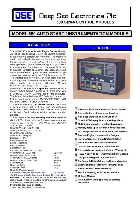
MODEL 550 AUTO START / INSTRUMENTATION MODULE<br />
DESCRIPTION<br />
The Model 550 is an Automatic Engine Control Module,<br />
which has been designed to allow the OEM to meet most<br />
of the industry’s complex specifications. The module is<br />
used to automatically start and stop the engine, indicating<br />
the operational status and fault conditions; automatically<br />
shutting down the engine and indicating the engine failure<br />
by means of an LCD display and a flashing LED on the<br />
front panel. Selected operational sequences, timers and<br />
alarms can be altered by the customer. Alterations to the<br />
system are made by using the 810 interface and a PC.<br />
This interface also provides real time diagnostic facilities.<br />
It is also possible to monitor the operation of the system<br />
either locally or remotely. (Optional: Remote<br />
Communications output versions only).<br />
Operation of the module is via pushbutton controls (with<br />
security locking facility) mounted on the front panel with<br />
STOP/RESET, AUTO, MANUAL and START pushbutton.<br />
The former three featuring LED ‘selected’ indications.<br />
Further pushbuttons provide MUTE/LAMP TEST, LCD<br />
PAGE and DISPLAY SCROLL functions.<br />
The module features 32-Bit Microprocessor control and<br />
a comprehensive list of timers and pre-configured<br />
sequences. This allows complex specifications to be<br />
easily met. Configurable expansion facilities are also<br />
provided .<br />
The 550 module provides metering and alarm facilities<br />
via the LCD display with the following instrumentation<br />
displays, accessed via the LCD PAGE and DISPLAY<br />
SCROLL push-buttons:-<br />
Generator Volts L1-N, L2-N, L3-N<br />
Generator Volts L1-L2, L2-L3, L3-L1<br />
Generator Amps L1,L2,L3<br />
Generator Frequency Hz<br />
Engine Speed RPM<br />
Engine Oil Pressure<br />
Engine Temperature<br />
Plant battery Volts<br />
Engine Hours Run<br />
Remaining time until Maintenance due<br />
Generator kVA L1,L2,L3, Total<br />
} Optional:-<br />
Generator kW L1,L2,L3, Total<br />
} On<br />
Generator pf L1,L2,L3,Average<br />
} Power<br />
Generator kVAr L1,L2,L3, Total<br />
} Measure-<br />
Generator KWh<br />
} ment<br />
Generator KVAh<br />
} Version<br />
Generator KVArh<br />
} Only<br />
Generator Phase Sequence }<br />
Synchroscope Display with check sync } CS versions<br />
The 500 series modules have been designed for front panel<br />
mounting. The module is fitted into the cut-out with the fixing<br />
clips removed. These are then fitted from the rear. Connection is<br />
via locking plug and socket connectors.<br />
Description continues overleaf...<br />
11/6/00 550sales_leaflet.doc Issue 4 MR<br />
FEATURES<br />
þ Advanced 32-Bit Micro-processor based Design<br />
þ Automatic Engine Starting and Stopping<br />
þ Automatic Shutdown on Fault Condition<br />
þ Graphic LCD Display for true Multi-lingual use<br />
þ Multi-lingual capability - 4 default Languages.<br />
þ Memory holds up to 4 user selected Languages<br />
þ PC Configurable via MS-Windows based software<br />
þ Provides Engine Instrumentation Gauges<br />
þ Provides Generator Output Instrumentation<br />
þ Provides Alarm and Status Information<br />
þ Simple Push-button Controlled Operation<br />
þ Remote telemetry and control via MS-Windows 5<br />
þ RS232 Modem or RS485 Communications Options<br />
þ Configurable Digital Inputs and Timers<br />
þ Configurable Relay Outputs and Alarm trip points<br />
þ Expansion Modules for further enhancement<br />
þ Audible and LED Alarm indication<br />
þ True RMS sensing for AC instrumentation<br />
þ 25 Event Memory<br />
þ Pre-Shutdown warning facility on selected<br />
protections
DESCRIPTION - CONTINUED<br />
The instrumentation displays are supplemented further by<br />
LCD display pages covering operating status and alarms.<br />
The selected page is displayed along with an LED tell-<br />
tale:-<br />
Status Page, Alarm Page, Engine Instruments Page,<br />
Generator Instruments Page, Event Log Page<br />
LED indication is provided for Alarm present.<br />
Un-committed LED’s allow the user to configure the<br />
module to provide other status indications from either<br />
internal states or from external digital inputs.<br />
The module accepts the following digital inputs;<br />
Emergency Stop Input - A N/C DC positive input<br />
9 Fully configurable warning or shutdown inputs<br />
With the exception of the Emergency Stop Input, these are<br />
configurable to be either N/C or N/O contacts connected<br />
the -Ve DC. The nine fully configurable auxiliary inputs can<br />
be selected to be indication, warning or shutdown inputs<br />
either immediate or held off during start up to allow for<br />
use as protection expansion inputs. Alternatively they may<br />
be configured to control extra functions such as manual<br />
load switching, lamp test or Remote start input, Generator<br />
start signal and many others - refer to appropriate<br />
manuals for details.<br />
Engine analogue inputs are provided for Oil Pressure and<br />
Engine Temperature. These connect to conventional<br />
engine mounted resistive sender units (such as VDO or<br />
Datcom Type) to provide accurate monitoring and<br />
protection facilities. Alternatively they can be configured to<br />
interface with digital switch type inputs for Low oil<br />
pressure and high engine temperature shutdowns.<br />
Relay outputs are provided for Fuel Solenoid Output, Start<br />
Output and four configurable outputs. The configurable<br />
relay functions can be selected from a range of 90+<br />
different functions, conditions or alarms. The relays<br />
supply positive plant supply out. Additional output relays<br />
can be added by means of up to two 157 Relay Expansion<br />
Modules. A total of 20 outputs are available with full<br />
expansion of the 550 Module. This allows the module<br />
system to be incorporation into existing telemetry or<br />
Building management schemes via Voltage free contacts.<br />
Refer to appropriate manuals for details.<br />
Multiple alarm channels are provided to monitor the<br />
following:-<br />
Under/Over Generator Volts<br />
Over-current<br />
Under/Over Generator Frequency<br />
Under/Overspeed<br />
Charge Fail<br />
Emergency Stop<br />
Low oil pressure<br />
High engine temperature<br />
Fail to Start<br />
Low/High DC Battery Volts<br />
Fail to come to rest<br />
Generator Short Circuit Protection<br />
Reverse Power (‘Power Measurement’ Version only)<br />
Generator Phase rotation error (‘PM’ Version only)<br />
Earth Fault Protection(‘PM’ Version only)<br />
Loss of speed sensing signal<br />
Fail to Sync (CS Version only)<br />
MPU Open circuit failure along with any configurable input alarms<br />
as selected. Alarms are indicated by an LCD Message, LED<br />
illumination and Audible Alarm.<br />
SPECIFICATION<br />
DC Supply:<br />
8 to 35 V Continuous.<br />
Cranking Dropouts:<br />
Able to survive 0 V for 50 mS, providing supply was at least<br />
10 V before dropout and supply recovers to 5V. This is<br />
achieved without the need for internal batteries.<br />
Max. Operating Current:<br />
513mA at 12 V. 263 mA at 24 V.<br />
Max. Standby Current:<br />
370 mA at 12 V. 210 mA at 24 V.<br />
Alternator Input Range:<br />
15(ph-N) to 277(ph-N) AC (+20%)<br />
Alternator Input Frequency:<br />
50 - 60 Hz at rated engine speed (Minimum: 15V AC Ph-N)<br />
Magnetic Pick-up Voltage Input Range:<br />
+/- 0.5 V to 70 V Peak<br />
Magnetic Input Frequency: 10,000 Hz (max)<br />
Start Relay Output:<br />
16 Amp DC at supply voltage.<br />
Fuel Relay Output:<br />
16 Amp DC at supply voltage.<br />
Auxiliary Relay Outputs:<br />
5 Amp DC at supply voltage.<br />
Dimensions:<br />
192 X 144 X 138<br />
Charge Fail / Excitation Range:<br />
0 V to 35 V<br />
Operating Temperature Range:<br />
-30 to +70°C<br />
NOTE:- An Automatic mains failure version of<br />
the 550 is also available (Model 555). This<br />
combines all the features of the 550 coupled with<br />
built-in mains monitoring and change-over<br />
contactor control. Please refer to <strong>Deep</strong> <strong>Sea</strong><br />
<strong>Electronics</strong> for details.<br />
TIMERS & INPUT FUNCTIONS<br />
þ Start delay timer<br />
þ Stop delay timer<br />
þ Crank/Crank rest/ timers<br />
þ Engage attempt and manual crank limit Timers<br />
þ Safety on delay timer<br />
þ Warm-up timer<br />
þ Cooling timer<br />
þ Energise to stop hold timer<br />
þ Pre-heat timer / Pre-heat bypass timer<br />
þ Smoke limiting control timers<br />
þ Fail to come to rest timer<br />
þ Over-speed overshoot timer<br />
þ Breaker pulse control timers<br />
þ DC Battery alarm delay timers<br />
þ Sync/Fail to Sync Timer (CS Versions Only)
BUILT-IN FUNCTIONS<br />
þ Alternator Under/Over Volts Warning/Shutdown<br />
þ Alternator Under/Over Freq. Warning/Shutdown<br />
þ Under/Over Speed Warning/Shutdown<br />
þ Low Oil Pressure Warning/Shutdown<br />
þ High Engine Temp Warning/Shutdown<br />
þ Low Battery Volts Warning<br />
þ High Battery Volts Warning<br />
þ Over-current Warning/Electrical Trip/Shutdown<br />
þ Reverse Power Electrical Trip/Shutdown (Option)<br />
þ Phase sequence Electrical Trip/Shutdown (Option)<br />
þ Earth Fault Shutdown (Option)<br />
þ Short Circuit Fault Electrical Trip/Shutdown<br />
þ Adjustable crank cycle/attempts<br />
þ Maintenance due alarm function<br />
þ External remote start input (On load/Off load)<br />
þ Analogue Sender Fault Alarm<br />
þ Built in Exercise Scheduler<br />
þ Magnetic Pick-up or Alternator speed monitoring<br />
þ Synchroscope with Check sync output (Option)<br />
þ Event Logging of Shutdown Alarms<br />
þ Full Remote Control and Telemetry (Option)<br />
þ Engine Instrumentation<br />
þ Alternator Output Instrumentation<br />
þ Compliant with BS EN 60950 Low Voltage Directive<br />
þ Compliant with BS EN 50081-2 EMC Directive<br />
þ Compliant with BS EN 50082-2 EMC Directive<br />
þ 9 Digital inputs - Fully user configurable<br />
þ 4 Configurable relay outputs (100+ Control functions)<br />
þ LCD Back-lighting for low light level operation<br />
þ Load switching auxiliary feedback inputs<br />
þ System lock input<br />
þ Load switching control push-button inputs<br />
þ Limited configuration from front panel - including<br />
user language selection<br />
TELEMETRY<br />
The 550 module provides the user with the option of full<br />
telemetry facilities via the optional communications<br />
software. The module can be either connected to the PC<br />
using the 810 interface or via a suitable modem<br />
(Optional: Remote Communications output version only<br />
RS232 or RS485 available).<br />
The PC software is MS-windows based and allows the<br />
operator to control the module from a remote location.<br />
The remote operator can also view the instrumentation,<br />
Alarm and Data log details, and the relay and input status.<br />
All access is password controlled so un-authorised<br />
operators cannot log onto the system.<br />
Additionally in the event of the module detecting an alarm<br />
condition, it will initiate a modem dial out to the host PC to<br />
inform the remote operator of the problem; giving<br />
identification of the module followed by the alarm event<br />
and the time and date of occurrence *.<br />
(*=Optional: Remote Communications output version<br />
only).<br />
EVENT CAPTURE<br />
The standard module features event capture facilities,<br />
this records the last 25 shutdown alarms allowing the<br />
operator to view the recent operating history of the module<br />
to assist in fault finding, etc.<br />
Event Log:-<br />
19 Apr2000<br />
14:34:14<br />
LOW OIL<br />
CONFIGURATION<br />
PC based configuration software allows for fast, simple<br />
and secure configuration of module parameters. Utilising<br />
the P810 interface to provide a safe isolated link to the<br />
PC, changes can easily be made to the system by<br />
authorised personnel.<br />
Complex configurations can be saved and loaded from<br />
disk or output to a printer for reference. Diagnostic<br />
facilities allow for fault finding and monitoring during test<br />
and installation.<br />
SYNCHROSCOPE (OPTION)<br />
Hz +0.9 V +0.2<br />
Environmental Testing Standards<br />
Electromagnetic Compatibility:<br />
BS EN 50081-2 EMC Emission Standard for the Industrial Environment<br />
BS EN 50082-2 EMC Immunity Standard for the Industrial Environment<br />
Vibration: BS EN 60068-2-6 Ten sweeps (up & back down) at 1<br />
octave/minute in each of three major axes<br />
5Hz to 8Hz @ +/-7.5mm constant displacement<br />
8Hz to 500Hz @ 2gn constant acceleration<br />
Cold Temperature: BS EN 60068-2-1to -30 0 C<br />
Hot Temperature: BS EN 60068-2-2 to 70 0 C<br />
Humidity: BS 2011 part 2.1 93% RH @ 40 0 C for 48 hrs<br />
Shock: BS EN 60068-2-27 Three half sine shocks in each<br />
of three major axes 15gn amplitude, 11mS duration<br />
Electrical Safety: BS EN 60950 Safety of information<br />
technology equipment, including electrical business<br />
equipment<br />
11/6/00 550sales_leaflet.doc Issue 4 MR
CASE DIMENSIONS<br />
137mm<br />
144.0mm<br />
:<br />
157<br />
808<br />
ü<br />
û<br />
CE<br />
110.0mm<br />
185.0mm<br />
192.0mm<br />
7.5mm<br />
Panel Cut-out:138mmx185mm<br />
TYPICAL CONNECTIONS<br />
Refer to Operators Manual for further Information<br />
LOAD<br />
L1 L2 L3 N<br />
NOTE:-<br />
When connected to a<br />
completed Panel / Gen-set<br />
Real-time diagnostic display<br />
is available<br />
810<br />
Configuration<br />
F<br />
F<br />
F<br />
Optional 157 Relay<br />
Expansion Board<br />
(Maximum 2 off)<br />
Safety Earth Connection<br />
Must be connected to<br />
the Safety Earth<br />
25 2627 29 34 33 32 31<br />
36 35<br />
40 39 38<br />
30<br />
Generator Loading FCC68 - 4 Way FCC68 - 8 Way<br />
Request Relay<br />
Generator Loading<br />
Relay<br />
1 2 3 5 4<br />
8 20 21 22 24 23 9 10 11 12 1314 15 16 17 6 7 18 19<br />
4<br />
F<br />
F<br />
MPU<br />
Oil<br />
Sender<br />
Temp<br />
Sender<br />
These Ground connections must be<br />
on the engine block and must<br />
be a sound electrical connection<br />
to the sender bodies.<br />
The wire to Terminal 24 must not<br />
be used to provide a ground<br />
connection to any other device<br />
5<br />
6<br />
7 Configurable inputs<br />
8<br />
9<br />
<strong>Deep</strong> <strong>Sea</strong> <strong>Electronics</strong> <strong>Plc</strong><br />
Mountside Park, Queen Margarets Road,<br />
Scarborough, YO11 2RH. ENGLAND<br />
Tel:- +44 (0)1723 377566 Fax:- +44 (0)1723 354453 E-Mail:- sales@deepseaplc.com