Create successful ePaper yourself
Turn your PDF publications into a flip-book with our unique Google optimized e-Paper software.
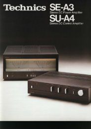
SU-8O8O<br />
stereo Intesrated DC Amplirier<br />
A fact which is often lost sight of in these<br />
days of proliferating audio products is that<br />
the first and foremost purpose of an amplifier<br />
is to amplify. To amplify the program source<br />
as accurately as possible, neither adding to<br />
nbr subtracting from the natural beauty of<br />
your music. Technics terms this Waveform<br />
Fidelity, and it's what we continuously strive<br />
to achieve in all our fine comoonents. ln the<br />
SU€080, our audio engineers have gone all<br />
out in their ouest for absolute Waveform<br />
New Integrated DC Amplifier for<br />
Maximum Waveform Fidelity<br />
The power amplifier of the SU€080 is a<br />
newlydesigned DC arnplifier to ensure the<br />
maximum in Waveform Fidelity. lt features a<br />
first stage differential amplifier, a purely<br />
resistive loaded voltage amplifier, an emitter<br />
follower and a two-stage Darlingtonconnected<br />
fully complementary output stage.<br />
Fidelity. Major features include our newlydesigned<br />
Integrated DC Amplifier, totally<br />
separate power supplies for each channel, a<br />
fantastically quiet equalizer circuit, direct high<br />
level input to the DC power amplifier, and<br />
dozens of other innovations. Read the<br />
following specifications and then listen to<br />
this amplifier perform. We're confident that<br />
you'll want to hear a whole lot more from the<br />
SU€080.<br />
For complete low frequency reproduction all<br />
the way down to 0 Hz, all coupling capacitors<br />
have been totally eliminated from the SU€080<br />
circuits. No capacitors will be found<br />
anywhere in the signal path: in the output<br />
stage, between stages, or in the NFB loop.<br />
Since capacitors cannot pass DC or any<br />
frequencies close to it, their use-and they are<br />
used in nearly all other amplifiers-places a<br />
distinct limit on lower range frequency<br />
response. Another advantage of the DC<br />
circuitry is the correction of another problem<br />
found in conventional amplifiers: phase<br />
dislocation of bass frequencies. Overall, then,<br />
the DC amplifier simply performs better and<br />
oermits much more accurate reproduction of<br />
the input signal and therefore better<br />
Waveform Fidelity. And that, we repeat, is the<br />
name of the game.<br />
To obtain the best from a DC amplifier, one<br />
should avoid using it with a non-DC<br />
preamplifier. That's why the SU€080 is<br />
designed so that high level inputs from Tape,<br />
Tuner, Aux etc., can be routed directly to the<br />
power amplifier without passing through any<br />
other circuits. That's what we mean by an<br />
"integrated" DC amplifier. When operated in<br />
this fashion, the DC power amplifier has a<br />
gain oI 42 dB (above O.O2Hz). And compared<br />
to a conventional amplifier, the SU8080<br />
delivers a considerably lower level of<br />
distortion as measured between the high level<br />
input terminals and the speaker terminals.<br />
When necessary, tone controls and/or filters<br />
can be switched in from the front panel, in<br />
which case the power amplifier gain is 28d8.<br />
The amplifier produces 72 watts per channel,<br />
minimum RMS, into 8Q from 20Hz to<br />
20,OOOHz, with a phenomenally low THD<br />
Ootal Harmonic Distortion) of less than<br />
0.027" at full rated power. When power drops<br />
down to 36 watts, the maximum level at<br />
which it would normally be used in most<br />
home applications, THD is an incredibly small<br />
0.0015% (1kHz).<br />
ln the first stage differential amplifier, the SU-<br />
8080 employs current mirror loading and<br />
Technics' unique dual packaged transistors<br />
which are well matched for thermal stability.<br />
Current mirror circuit construction means that<br />
only the initial stage has any bearing on the<br />
amp's DG balance. In order to always keep<br />
the DC base potential strictly at zero, a DC<br />
bias has been provided for proper operation.<br />
Whenever there is a danger of pure DC<br />
leaking into the DC amplifier-an undesirable
situation from the standpoint of speaker<br />
proleclion-you reed only switgh in the Low<br />
Cut Filter. This effectively cuts off all<br />
signals below 2Hz and slinrinates any<br />
possibility of problems. In addition, should<br />
more than *2.5V of direct current appear at<br />
the output terminals of the power amplif ier.<br />
the speakers are electronically disconnected<br />
from the amplif ier to prevent speaker damage<br />
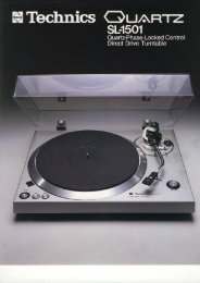
10 Hz Sguare Wave Response Ouner Input*Speaker Output)<br />
DC Amplifier Circuit Diagram<br />
Stabilized voltage<br />
power suppry +'"1 I<br />
Emitter I<br />
f ,J:1".119"_,-----i"-rloI'jl:l1P_gyt!:!'j"s'<br />
Output<br />
Integrated Amp. with only power<br />
amplifier DC<br />
10 Hz -Wave 8.Rest Tone Burst Response (funer Input*Speaker Output)<br />
Current mirror load Direct input {integrated DC}<br />
lntegrated Amp. with only power<br />
Output Power vs. T.H.D.<br />
8<br />
:<br />
.2<br />
E<br />
6<br />
6<br />
F<br />
T.H"D. vs. Frequency<br />
Super Silent Phono Equalizer:<br />
BBdB S/N Ratio<br />
To accompany this superb power amplif rer.<br />
Technics audio engineers were not contento<br />
include a conventional phono equalizer in the<br />
SU-8080. and a malor effort was launched to<br />
f ind ways to achieve the same kind of<br />
super,o'perlormanLe in tie equalrzer lhal rie<br />
DC amplif ier affords. Efforts centered on the<br />
elimination of noise from the equalizer circuits.<br />
the k nd of noise that you can hear in a<br />
conventionai amplif rer by placing the input<br />
seiector switch to Phono and turning up the<br />
volume. lt was found that to reduce noise (i.e.<br />
increase the S/N ratio) both circuit noise and<br />
transistor internal noise would have to be<br />
tackled. Conventional low noise transistors<br />
were tound to be lacking. and still produced<br />
noise after circuit noise had been reduced.<br />
Thus, a transistor newly developed by<br />
Technics was employed. This was the M47L.<br />
which is beyond compare in its low noise<br />
characteristics. lt is used jn the f irst stage<br />
differentia amplif ier operated with a current<br />
mri'ror load to produce an extremely low noise<br />
operating current. The result is an un<br />
precedentedly high phono S/N ratio in the SU-<br />
B0BO ot BBdB at a sensitivity of 2.5mV (lHF-A).<br />
You will notice the difference with a regular<br />
high impedanccartridge, but the difference<br />
is really /mpress ve when using a low m-<br />
pedance N,4M cartridge at high volumes. Other<br />
imponant steps in achieving superb phono<br />
equalizer performance include the use of Met<br />
alrzed polyester f ilm capacitors as the coupling<br />
capacitors for the input and output stages (to<br />
ensure that no d stoftron is present even n<br />
the inaudible range). and the use of pre.isron<br />
componenls lh.ouqhoJlhe trquaii.,tr' r i'cu'try<br />
Metalized f ilm resistors with a tolerance oi<br />
only +1 ?;. and polypropylene capacitors wtth a<br />
tolerance of 2" are uspd e^r^lus vply t h s<br />
permrts the achievement of extreme y accurate'requency'eponse<br />
lhroLrghoul lhe<br />
entire aildio range. Variation f rom the stan'<br />
dard RIAA curve rs no more than +0.2d8.<br />
The to lowing graph shows the relationship<br />
between input voltage and total harmonic<br />
drstodion of the SU€080 phono equalizer<br />
amplif ier. Total harmonic distortion remains<br />
extremey low even in the low frequency<br />
range whertr ltp ef f ect of NFB is snai . high<br />
input levels up to 280mV can be handled<br />
without causing distorlion or other quality<br />
degradations, so that even high output<br />
cafiridqps lrachir-g disc> of hiqh cuttirg<br />
levels will be accommodated withouthe<br />
slightest problem<br />
m)<br />
"$-<br />
f:1 J "r'<br />
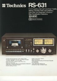
N447L Ultra-Low Noise Transistor
500)<br />
o<br />
.9<br />
'o<br />
6<br />
o<br />
6<br />
Phono Equalizer Noise Spectrum<br />
Equalizer Subsonic Filter<br />
A sharp subsonic f ilter built into the equalrzer<br />
circuit permits the operator to cut off all<br />
sounds below 30Hz (12dBloct) at the f lick of a<br />
switch. This eliminates low frequency<br />
vibrations picked up by the cartridge f rom<br />
warped records, etc.. and prevents these<br />
sounds from muddying the low frequency<br />
range ol your musrc.<br />
Equalizer Subsonic Filter Effecl<br />
because too much current s drawn away<br />
from the one channel to be used in the other.<br />
This is known as transient crosstalk. The<br />
most elegant way to eliminate this problem rs<br />
to utilize separate, independent power<br />
supplies for each channei. This is exactly<br />
ia,hal Tcehnieq enoineerq haVe bUill inlO lhe<br />
SU€080. lt utilizes two hefty power transformers<br />
and four oversized 10,000 gF<br />
electrolyticapacitors along with two<br />
separate rectifier circuils lor lolal separalio'r<br />
of the two supplies. This complete,y solves<br />
the problem of transient crosstalk. In addition,<br />
the power supply for the voltage<br />
amplif ier stage in both the power amp and<br />
the preamp are of the constant voltaQe type<br />
which means that both transient distortion in<br />
each channel and self{ransient distorlion are<br />
greatly suppressed. producing an amplif ier<br />
with excellent dynami characteristic.<br />
The two transformers are arranged on the<br />
chassis in such a way that they largely cancel<br />
out each other's leakage flux. thus contributing<br />
to the excellent S/N ratio.<br />
dB<br />
dB<br />
Phono Equalizer Circuit Diagram<br />
Dilferenhal<br />
I<br />
rei<br />
M17L n47L<br />
t\'<br />
I<br />
I<br />
I<br />
I<br />
L-<br />
J<br />
nll<br />
H f<br />
\ r-;;;-L<br />
Cu rren mirror load<br />
rJ eo L-<br />
Phono Equalizer Input Voltage vs.<br />
Total Harmonic Distorlion<br />
Frequency (Hz)<br />
Switchable Input ResistanceiCapacitance<br />
Settings<br />
The impedance of the phono input has a<br />
subtle but important effect on the quality of<br />
sound produced. ln the SU€080. the input<br />
resistance is switchable between 27ka and<br />
47kQ, while the capacitance may be switched<br />
belween high and low. This grves a loral oI<br />
four possible combinations. thus allowing the<br />
SU€080 to accommodate the whole range of<br />
cartridges available on the market today. (For<br />
low oLrpul MC carlridges a separate prepreamp<br />
or step-up transformer will be<br />
needed.)<br />
Additional Features of the<br />
SU.BOBO<br />
Completely Independent Power Supplies lor<br />
Each Channel<br />
The test of a quality amplif ier is how it<br />
resoonds to music lransients. lhose sharp.<br />
loud. sudden sounds that occur so frequently<br />
in many kinds of music. A poor amplifier<br />
cannot handle these transients and distorts<br />
the music in a very noticeable manner. The<br />
cause is insufficient power supply capacity<br />
for both channels. and often the transients<br />
occurring on one channel will end up<br />
distorting the music on the other channel<br />
New Type Tone Controls<br />
When the selector switch on the f ront panel<br />
of the power amp is switched to the "via<br />
tone" position, the tone controls are placed in<br />
operation and adjustments to the sound may<br />
be made. But the tone controls of the SU-<br />
8080 have a unique dif ference, for when they<br />
are in their center positions, the tone control<br />
ci.cuit componerts ('esisto's and capacilors)<br />
are removed from the circuit and the<br />
trequency response is totally flat.<br />
Dynamic Range Unaflected by Muting Circuit<br />
Audio muting is accomplished by altering the<br />
power amplif ier's NFB by 14d8. This differs<br />
f rom the conventional method which is to<br />
introduce resistance af ter the volume control.<br />
The vidue of this new approach is that the<br />
dynamic range is not altered, although the<br />
noise is decreased in volume. lt also means<br />
that the audio muting takes place af ter the<br />
tone amplif ier when the seleclor switch is in<br />
the via tone position.<br />
Precise, Error.Free Volume Control<br />
The volume control is a precision'crafted<br />
continuously variable device to permit accurate<br />
adjustment of playing volume level.<br />
The circuit utilizes 17o tolerance metal film<br />
resistors in the NFB loop of each channel's<br />
amplif ier and maintains gain difference within<br />
0.5d8, so that the left-right balance between<br />
the channels does not vary when the volume<br />
is adjusted up or down.<br />
Versatile Controls<br />
The SU€080 has facilities to accommodate<br />
two tape decks, and dubbing in either<br />
direction is possible. The rec mode and tape<br />
monitor switches are independent, so you<br />
may play records or listen to the FM tuner<br />
while dubbing tape{o{ape. This convenient<br />
feature permits great f lexibility and allows<br />
maximum enjoyment of your equipment.<br />
High Filter<br />
An effective high f ilter engaged from the front<br />
panel eliminates irritating high frequency<br />
norses such as record scratches and tape<br />
N ISS,<br />
dB)<br />
) dB.<br />
5dB<br />
7.5 dB<br />
7.5 dB<br />
x<br />
I<br />
v /240 v<br />
_-1<br />
I<br />
Ir<br />
)<br />
__i<br />
20E
Why a DC Amplifier?<br />
In conventional amplif iers, extremely low<br />
frequency sounds are not amplified because<br />
as OHz is approached, intra- and inter stage<br />
capacitors block the signals and fail to let<br />
them travel through ihe circuit. This not only<br />
harms low lrequency gain but also has adverse<br />
affecis on phase response. In the DC<br />
amplifier, those lows all the way down to OHz<br />
are amplified, thus ensuring the most accurate<br />
possible reproduction of the incoming<br />
signal and guaranteeing maximum Waveform<br />
Fidelity.<br />
This is accomplished by totally eliminating<br />
capacitors from the signal path stages and<br />
connections between them. By their very<br />
nature, capacitors block the flow of direct<br />
current, and as a consequence the very low<br />
frequency sounds tail to ever reach the<br />
amplifier circuits. In a very real sense, the<br />
recent history of audio amplif iers has been<br />
the history of the elimination of capacitors<br />
from ampltfier circuits. First they were<br />
eliminated from the output stage in the OCL<br />
(output capacitorless) amplif iers and from<br />
between the stages in the direct coupled<br />
amplifier. Now they have been eliminated<br />
from the NFB loop as well, permittjng total,<br />
complete DC amplification<br />
Naturally, the process is much more complicated<br />
than merely removing the capacitors.<br />
The elimination of coupling capacitors is not<br />
a simple task, and Technics engineers had<br />
many problems io solve to achieve this.<br />
Actually to ensure complete DC and temperature<br />
stability in the power amplifier stage,<br />
a complete redesign and upgrade of the<br />
circuitry was required. A great deal o{ destgn<br />
attention was given to making circuits as<br />
exact as possible, and only the most precise,<br />
narrow tolerance components could be<br />
utilized so as to keep all sources of DC from<br />
getting into the circuits, for even a single<br />
trace of direct current is amplified by the DC<br />
amplifier and appears at the output.<br />
6<br />
b +120<br />
3 +80<br />
a +44<br />
c<br />
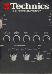
Phase vs.Frequency Response<br />
i 10 100 1K<br />
Frequency {Hz)<br />
Gain vs.Frequency Response<br />
Non-Dclamp.'<br />
i>,<br />
10 100<br />
Frequency {Hz)<br />
1K<br />
10 Hz Square Wave Response<br />
Power supply<br />
ry-*"fi*,,* t{U<br />
,lr<br />
nt7..P<br />
S<br />
power amp<br />
_l<br />
POWer -l<br />
transformers<br />
lst stage dlf ferential<br />
amp<br />
Protection circuit<br />
and relay (lower -<br />
printed circuit<br />
board)<br />
.;{<br />
q{<br />
ffi<br />
, ':11;<br />
ll .,<br />
.1..f<br />
- Right ch. power<br />
amp.<br />
- - Regulated power<br />
SUPP Y<br />
ltl ,ll t'l I<br />
*g<br />
.ffitr<br />
${<br />
l_ i lone control clrcull
Rear Panel Facilities<br />
2345<br />
Technical<br />
Specif ications (o'.r 45oo)<br />
1. Ground terminal<br />
2. Phono 1 inputs<br />
3. Phono 2 inputs<br />
4. Tuner inputs<br />
5. Aux inputs<br />
891011 12<br />
6. Speaker terminals (main)<br />
7. REC/ PLAY terminal (Taoe deck 1)<br />
8. Tape deck 1 REC outputs<br />
9. Tape deck 1 PLAY inputs<br />
'10.<br />
Tape deck 2 REC outouts<br />
IJ<br />
11. Tape deck 2 PLAY inputs<br />
12. Pre-out/Power-amp-i n terminals<br />
13. Speaker termrnals (remote)<br />
POWER AMPLIFIER SECTION<br />
1 kHz continuous power<br />
both channels driven<br />
40 Hz-1 6 kHz continuous power<br />
both channels driven<br />
20 Hz-20 kHz continuous power<br />
both channels driven<br />
Total harmonic distortion<br />
rated power at 1 kHz<br />
rated power at 40 Hz*16 kHz<br />
rated power at 20 H?zO kqz<br />
halt power at 1 kHz<br />
-26 dB power at 1 kHz<br />
50 mW power at 1 kHz<br />
Power bandwidth<br />
both channels driven at 4 O<br />
both channels driven at I O<br />
Frequency response<br />
s/N (rHF, A)<br />
Residual hum & noise<br />
Damping lactor<br />
Input sensitivity and impedance<br />
Headphones level and output<br />
rmpedance<br />
Load impedance<br />
MAIN or REMOTE<br />
MAIN+REMOTE<br />
2x92W r''a\<br />
2x74 W (8 O)<br />
2x9O W (4 O)<br />
2x72 W (8 O)<br />
2x90 w (4 O)<br />
2x72W l8 A\<br />
0.02% (4 o, 8 o)<br />
0.05% (4 o)<br />
0.02ol. (8 o)<br />
0.05% (4 o)<br />
0.0?/. (8 o)<br />
0.0015% (4 o, I o)<br />
0.08% (4 o)<br />
0.1s% (4 o)<br />
5 Hz-40 kHz, 3 dB<br />
5 Hz-40 kHz, -3 dB<br />
20 Hz- 20 kHz,<br />
+0 dB, -0.1 dB<br />
DC-10O kHz,<br />
+0 dB, -3 dB<br />
115d8<br />
100 UV<br />
35 (4 O), 70 (8 O)<br />
1V/47 ka<br />
550 mv/$o f)<br />
4-16 c)<br />
8-16 f)<br />
The ST-8080 is just the right companion for your SU€080. With the same bold, attractive<br />
styling and outstanding performance standards, it perfectly complements the SU-8080<br />
lntegrated DC Amplifier.<br />
PREAMPLIFIER SECTION<br />
Input sensitivity and impedance<br />
PHONO 1, 2<br />
TUNER, AUX<br />
PLAYBACK, REC/PLAY<br />
Phono maximum input voltage<br />
(1 kHz, RMS)<br />
Total harmonic distortion<br />
S/N<br />
rated power PHONO 1,2<br />
TUNER, AUX<br />
2.5 mV/47 krl,27 kA<br />
200 mV/35 kO<br />
200 mV/35 kO<br />
280 mV<br />
o.o10h<br />
-26 dB power PHONO 1,2 65 dB<br />
TUNER, AUX 67 dB<br />
50 mW power PHONO 1,2 60 dB<br />
TUNER. AUX 62 dB<br />
Frequency response<br />
PHONO 1,2<br />
TUNER, AUX<br />
Tone controls<br />
BASS<br />
70 dB (lHF, A: 88 dB)<br />
92 dB (lHF, A: 100 dB,<br />
via tone)<br />
(lHF, A: 106 dB,<br />
direct)<br />
RIM standard curve<br />
!:0.2 dB<br />
20 H?20 k{z,<br />
+0 dB, -0.1 dB<br />
50 Hz, +7.5 dB- 7.5 dB<br />
20 kHz, +7.5 dB- 7.5 dB<br />
30 Hz, - 12 dBloct.<br />
FEBLE<br />
Equalizer subsonic filter<br />
High filter<br />
Loudness control (volume at -30 10 kHz, -6 dB/oct<br />
dB) 100 Hz, +8 dB<br />
Muting<br />
-14 dB<br />
Output voltage<br />
PRE OUT (rated)<br />
(max.)<br />
9V<br />
REC OUT<br />
200 mV<br />
BEC/PLAY<br />
30 mV<br />
Channel balance (250 Hz-6300 Hz) t1.0 dB<br />
GENERAL<br />
Power consumption<br />
Power supply (50 Hzl60 Hz)<br />
Dimensions (WxHxD)<br />
Weight<br />
490 W<br />
110 V/120 V/220 V/240 V<br />
450x 140x371 mnr<br />
117-23/32"x5-1 /2'<br />
x'14-19/32")<br />
14 kg (30.9 lb.)<br />
@Technics<br />
Matsushita Electric<br />
Specifications subject to change without notice. Printed in Japan SD7D05o2oE