Create successful ePaper yourself
Turn your PDF publications into a flip-book with our unique Google optimized e-Paper software.
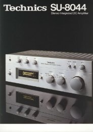
SE-A3<br />
Our New Class A Circuitry<br />
Eliminates Switching and<br />
Crossover Distortion<br />
The SE-A3 power amplifier employs our New<br />
Class A circuitry, and that makes it something<br />
special. New Class A is a unique Technics<br />
design that provides the distortion-free fidelity of<br />
class A amplifiers and the high power efficiency<br />
of class B (orAB) amplifiers. The SE-A3delivers<br />
a rated output of 200 watts pet channel, both<br />
channels driven into 8 ohms, with no more than<br />
0.002% total harmonic distortion from 20 to<br />
20,000 Hz. Signal-to-noise ratio is 123 dB (lHF A)<br />
and TIM is so low that it is unmeasureable.<br />
Although these specilications speak for<br />
themselves, note that our New Class A circuitry<br />
eliminates the switching distortion and<br />
crossover distortion that are characteristic of<br />
conventional amplifiers other than the inefficient<br />
class A type. The SE-A3 power amp's freedom<br />
from such distortions is evident in an<br />
oscilloscope trace of its output waveform.<br />
And, the vibrant musicality you hear is the end<br />
result.<br />
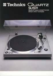
Class B amDlilier output<br />
waveform and disbrtion<br />
waveform (at 20 kHz)<br />
stereo DC PowerAmplifier<br />
New class A amplitier output<br />
wavefom and disbrtion<br />
wavefom (at 20 kHz)<br />
Synchro-Bias: The Key to Class A<br />
Fidelity with Class B Efficiency<br />
Class A amplifiers use a single outputransistor<br />
to handle the entire waveform. Class B and AB<br />
amplifiers use an "upper" transistor to handle<br />
the positive half-cycle, and a "lower" transistor<br />
to handle the negative half-cycle of the<br />
waveform.<br />
The class A amplifier wastes a lot of power<br />
because the transistor is biased so that it draws a<br />
large idling current (the quiescent current drawn<br />
during zero input signal conditions). In contrast,<br />
the upper and lower transistors in a class B<br />
amplifier are biased so that there is no idling<br />
current drawn until the transistor is "turned on"<br />
so that it can begin amplifying either the positive<br />
or negative half-cycle. Therefore, class B is<br />
much more efficient. Unfortunately, the class B<br />
design also generates two kinds of distortion:<br />
"switching" and "crossover". Switching<br />
distortion, as its name implies, occurs when the<br />
outputransistorswilch on and off as they begin<br />
and end their roles in the amplification process.<br />
This causes an asymmetrical waveform with<br />
pulsive distortion. Crossover distortion shows up<br />
as a nonlinearconnection between the positive<br />
and negative half-cycles at the zerc crossover<br />
point. At Technics we have eliminated both types<br />
of distortion by enploying our original "synchro<br />
bias" circuit. This circuit is synchronized with the<br />
inputwavetorm, and constantly supplies bias<br />
currento the power transistorso they do not<br />
turn off. Therefore, there is no switching or<br />
crossover distortions.<br />
Although some manufacturers are offering<br />
superficially similar circuitry, a closer<br />
examination reveals that their variable bias<br />
circuitry depends on feedback ot the output<br />
waveform. With thistype of system, however,the<br />
biascurrent isprovided bythe same route asthe<br />
audio signal circuitry, so that the bias current<br />
varies as needed. Because the bias current<br />
varies, it is ditficulto achieve a completely<br />
symmetrical crossover, and crossover distortion<br />
becomes a problem.<br />
In our New Class A design, the synchro bias<br />
ciriuit is separate from the audio signal route and<br />
employs high speed diodes for bias control.<br />
The resoonse characteristics of these diodes<br />
permit a current waveform, rising edge that is<br />
very close to the ideal parabolic function so that<br />
linearity is excellent at the zero cross point, and<br />
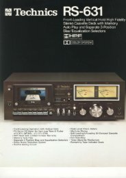
there is virtually no crossover distortion. Our 3DA<br />
(3-dimensional analysis) profile for the SE-A3<br />
supports this ingenious design approach.<br />
Low distortion<br />
maintained throughout a wide,<br />
smooth plane eitending from 0.2 W to rated<br />
power (200 W) and from 10 Hz to 100 kHz.<br />
Low Distortion DC Circuitry<br />
While many of today's amplifier's tend to relytoo<br />
much on negative feedback (NFB) to reduce<br />
distortion caused by basic amp circuitry, the<br />
SE-A3 design effectively reduces distortions<br />
before NFB is applied. Open-loop distortion<br />
low, a condition that usually indicates<br />
outstanding sound quality.<br />
The excellent open loop performance of lhe<br />
SE-A3 rests on elaborate DC circuitry employing<br />
no coupling capacitors from input jacks to output<br />
speaker terminals. (There are no capacitors in<br />
the feedback loop either.)<br />
The first stage is a current mirror loaded<br />
bootstrap cascode differential circuit using onechip<br />
dual FETs for thermal stability. These dual<br />
FETs reduce DC drift of the SE-A3 to a miniscule<br />
+10 mV between -10'C and +50"C.<br />
Downstream circuitry includes a current mirror<br />
loaded double cascode differential voltage amp<br />
stage,a 2-stage class A SEPP driver stage, the<br />
svnbhro bias circuit, a2-parallel SLPT (Super<br />
Linear PowerTransistor) push-pull driver,'and a<br />
4-oarallel DLPT (Dual Linear Power Transistor)<br />
output stage. Also by utilizing NFB properly we<br />
have achieved incredibly low distortion of no<br />
more than 0.0027o at rated output of 200 W+200<br />
W, both channels driven into 8 ohms from 2O Hz<br />
to 20,000 Hz. At half rated power, distortion<br />
drops to 0.001 % or less, so low that it is no longer<br />
detectable by most test instruments. Frequency<br />
response is DC- 300 kHz (-3 dB), power<br />
bandwidth is 5 Hz-100 kHz (0.008% THD),<br />
signal-to-noise ratio is 123 dB (lHF A), and slew<br />
rate is 200V/ps.<br />
Concentrated Power Block Cuts<br />
Electromagnetic Induction<br />
Current flow creates magnetic fields which, in<br />
turn, can aflect other signals in nearlcy circuib.<br />
Such "electromagnetic induction" is a problem<br />
when dealing with the power supply and output<br />
transistors.<br />
That is why we utilize something called the<br />
"concentrlted power block", or CPB, for short'<br />
In our CPB, all circuitry<br />
handling large<br />
currents is<br />
connected by<br />
the shortest<br />
routes possible<br />
to help<br />
orotect small<br />
signal circuitry<br />
from adverse<br />
interference.<br />
Super Audio Capacitors, DLPTS,<br />
anal 3-Layer Bus Lines for High<br />
Frequency Handling AbilitY<br />
The DLPTs in the output stage were developed<br />
specifically for the SE-A3. These consist of<br />
matched NPN and PNP power transistors manufactured<br />
together in a symmetrical configuration<br />
so that emitter resistance is not dispersed.<br />
The result is an output waveform that looks very<br />
much like a class A waveform.<br />
We also utilize low-impedance electrolytic<br />
capacitors foraudio applications. Four lowinductance<br />
flat capacitors connected in parallel<br />
make up one of these plastic encased super<br />
audio capacitors. Two such 22,000 g.F<br />
capacitors are used for each audio channel.<br />
3-Layer laminated bus lines .r-<br />
are u'sed for the positive<br />
and negative<br />
power supply<br />
and output<br />
power line.<br />
Independent Left and Right Channel<br />
Power Transformers<br />
To eliminate chances of cross-channel<br />
interference, we have equipped this amp with<br />
separate transformerslorthe leftand right stereo<br />
channels.<br />
The voltage amplification stage employs a<br />
stabilized voltage power supply with stabilized<br />
current buffer.<br />
Large Peak Power Meters<br />
These large, high quality meters have an attack<br />
time of only 50ps and give direct readings from<br />
0.0001W to full eower.<br />
Other Features<br />
.Pushbutton speaker system selection: A, B,<br />
A+8, off.<br />
.Protection relay with automatic recovery and<br />
LED indicator.<br />
oDC low-cut (2 Hz) input iacks in addition to<br />
regular jacks.
SU-A4<br />
State-of-the-Art Performance for<br />
Today's Audio Systems<br />
The SU-A4 is a state-of-the-art control amo.<br />
It follows in the tradition of the SU-A2 introduced<br />
two years ago, just as the SE-A3 power amp<br />
follows the well respected SE-A1 .<br />
Besides this unit's impeccable credentials as a<br />
phono EQ preamp, it handles controlfunctions in<br />
an audio system. To prevent switching and<br />
crossover distortion, all amplifier stages are<br />
class A. ICL circuitry includes the MM and MC<br />
inputs employing FETs. And the only coupling<br />
capacitors are one for downstream MC and<br />
anotherfor MM, making this amp capable of<br />
straight DC amplification from AUX inputs to<br />
output.<br />
Thanks to a special buffer amp, output<br />
impedance isso lowthatyou can putyourpower<br />
amp as close to the speaker systems as<br />
possible, yet have the SU-A4 convenient to your<br />
listening position without affecting waveform<br />
fidelity. In addition to the usual tone controls,<br />
Super-Bass and Super-Treble controls let you<br />
effectively deal with typical audio equalization<br />
problems.<br />
Class A Circuitry Throughout<br />
Thanks to class A amplif ier circuitry f rom inputo<br />
output, the reproduced waveform is complelely<br />
free from switching and crossover distortion.<br />
Open loop performance is so good that little NFB<br />
is required.<br />
Straight DC Circuitry<br />
All high-level inputs (tuner, tape, aux) encounter<br />
no capacitors in the signal path. FETs are<br />
employed to eliminate the need for input<br />
capacitors. When used with a DC power amp<br />
such as the SE-A3 this means that DC<br />
amplification extends all the way to the speaker<br />
terminals, theadvantageof whichcan beseen in<br />
the excellent 3DA profile obtained for this control<br />
amplifier. Basic circuitry consists of the ICL prepreamp<br />
(MC), ICL phono equalizer amp, DC flat<br />
amp and buffer amp. Distortion is extremely low<br />
and frequency respons extends from DC to<br />
400 kHz (-3 dB), thanks to the 2-stage flat amp<br />
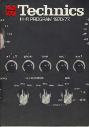
o<br />
@<br />
@<br />
Block Diagram of the SU-A4<br />
Stereo DCControl<br />
Amplifier<br />
and bufferampconstruction with acurrent mirror<br />
loaded cascode differential input stage<br />
employing matche dual FETs and an SEPP<br />
output stage employing SLPTs (Super Linear<br />
PowerTransistors) which feature an extremely<br />
high f1.<br />
Ultra-Low Noise FET Inputs for<br />
Phono EQand MC Pre-preamp<br />
The design utilizes ICL (lnput Capacitor-Less)<br />
circuitry employing ultra-low noise FETs, and<br />
only one coupling capacitor lor the phono EQ<br />
and another for the MC pre-preamp.<br />
This contributes to excellent phono specifications<br />
such as: 90 dB S/N for MM cartridges<br />
(2.5 mV, IHF '66), 78 dB for MC (25O p"Y,<br />
IHF'66), O.OO1 % distortion (2O Hz-2O kHz,<br />
MM-preout), and RIAA deviation of +0.15 dB<br />
(2OHz-20 kHz). Phonooverload is prevented<br />
by the MM maximum input of 300 mV/47 kilohms<br />
and MC of 12mV/47 ohms.<br />
No matter what type of preamp circuitry you<br />
compare these specs with, it is obvious that the<br />
SU-A4 offers true state-of-the-art performance.<br />
An equalizer subsonic filter is provided to prevent<br />
amplification of subsonic noise that might be<br />
transmitted from record warps or off-center<br />
spindle holes.<br />
Extremely Low Output lmpedance<br />
Allows Remote PowerAmp<br />
Placement<br />
Placing the power amp close to the speaker<br />
systems can improve damping ability, so<br />
speaker cone movement is better controlled.<br />
However, this can cause unexpected problems<br />
such as self-oscillation when the preamp is<br />
placed farawayfrom the poweramp if the output<br />
impedance of preamp is too high. Unfortunately,<br />
this is the case with many preamps. But not with<br />
the SU-A4. Because the A4's buffer amp drops<br />
output impedance to a mere 0.2 ohm, so low that<br />
you could use up to 110 yards of shielded wire for<br />
connections, orconnect as many as 2,500 power<br />
amps without problems. This is why a 20 kHz<br />
square wave can be reproduced with such<br />
excellent fidelity.<br />
A current limiter protection circuit is provided to<br />
protecthe output stage from accidental short<br />
circuiting.<br />
Super-Bass and Super-Treble<br />
Controls for Equalization<br />
To obtain outstanding low and high frequency<br />
responsewith today's audio systems and source<br />
material, you need more equalization facilities<br />
than are supplied on conventional preamps. That<br />
is whywe have developed new Super-Bass and<br />
Super-Treble controls in addition to the regular<br />
bass and treble controls on the SU-A4.<br />
The Super-Bass control has a steep 12 dBl<br />
octave slope to give a shelving boost of as much<br />
as 12 dB and thereby extend speaker system<br />
bass response by as much as one lull octave.<br />
The turnover frequency is continuously<br />
adjustable from 50 Hz to 200 Hz to give you<br />
precise control with any speaker system.<br />
Naturally, thisSuper-Bass<br />
alsovery helpful for<br />
dealing with other low frequency problemsuch<br />
as those caused by listening room acoustics or<br />
speaker position. Boominess of this variety can<br />
be dealt with by attenuating the conventional<br />
bass tone control and then turning up the<br />
Super-Bass. In the high range, the typical<br />
response problems are caused by phono<br />
cartridge characteristics. MM cartridges often<br />
exhibit dips around 5-6 kHz and MC cartridges<br />
may have annoying high range peaks. By using<br />
the regular treble control and the Super-Treble<br />
control where appropriate, you can obtain flat<br />
response for almost all situations.<br />
Of course, alltone control circuitry can be<br />
switched out byturning off the VIATONE switch.<br />
This gives you pure straight DC amplification<br />
(indicated by a front panel LED).<br />
Shelving Tone Control Characteristics<br />
Carefully Selected Electronic<br />
Components<br />
Conductive plastic (CP) and multi-contact<br />
brushes are used for the volume control and all<br />
selectors and switches. The volume control is<br />
2-ganged for each channel (on either side of the<br />
flat amp) to prevent noise when the volume is<br />
turned down. Extremely accurate decibel<br />
indications, aligned with the aid of a computer,<br />
contribute to handling convenience. Metal film<br />
type resistors are used throughout to obtain a<br />
15 dB improvement in distortion at 30 kHz as<br />
compared with ordinary carbon resistors.<br />
The extra{arge transformer contributes to this<br />
amp's outstanding signal-to-noise ratio.<br />
Other Features<br />
oA loudness tap is provided on the CP volume<br />
control. This is switchable between two<br />
turnover frequencies: 500 Hz for small<br />
speakers, and 250 Hz lor large speaker<br />
systems.<br />
o-20 dB audio muting switch.<br />
.REC OUT rnode selector for greater tape deck<br />
handling flexibility.<br />
.Two sets of preout jacks and two preout onloff<br />
switches.<br />
oRemovable control panel door and control<br />
setting merno card.<br />
oAll rear panel jacks are gold plated.<br />
oTwo sets of phono inputterminals and two sets<br />
of tape terminals.
Technical Specifications (DlN 45500)<br />
SE.A3<br />
AMPLIFIER SECTION<br />
20Hz-zOk}]'z @ntinuous power outpul<br />
bolh channels driven 320 Wxz (4O)<br />
200 Wx2 (8O)<br />
40 Hz-1 6 kHz continuous power output<br />
both channels driven 320 Wx2 (4o)<br />
200 wx2 (80)<br />
1 kHz continuous poweroutput<br />
both channels driven 350 Wx2 (4O)<br />
22OWx2$A\<br />
Total harmonic distortion<br />
rated power at 1 kHz<br />
0.003% (4o), o.oo1% (8o)<br />
at 40 Hz-1 6 kHz<br />
0.0039t' (4o), 0.002% (8o)<br />
atz0Hz-zOkHz<br />
o.oo3% (4o), o.oo2% (8o)<br />
halfpower al20Hz-2okHz<br />
0.002% (4o), 0.001% (8o)<br />
at 1 kHz<br />
-26 dB oower at 1 kHz<br />
50 mW oower at 1 kHz<br />
SIJ-A4<br />
0.0005% (40), 0.0003% (8f))<br />
0.001% (4())<br />
0.001% (40)<br />
Total harmonic distortion<br />
(20H2--20kqz\<br />
PHONO MM<br />
0.001 % (1 V output at vol. -30 dB)<br />
0.001 % (5 V output al vol. max.)<br />
PHONO MC<br />
0.0015% (1 Voutputatvol. 30dB)<br />
0.0015% (5 V output at vol. max.)<br />
TUNER. AUX. TAPE<br />
0.001% (1 Voutputatvol. 30dB)<br />
0.001 % (5 V output at vol. max.)<br />
Input sensitivity/impedance<br />
PHONO 1 (MC) 100pV/47ohms<br />
PHONO 1 (MM) 2.5 mV/47 kilohms<br />
PHONO 2 (MM) 2.5 mV/47 kilohms<br />
TUNER. AUX. TAPE 150 mV/47 kilohms<br />
Phono max. input voltage<br />
(THO 0.01%)<br />
PHONO MM 300 mV ('l kHz, RMS)<br />
'12<br />
PHONO MC<br />
mV (1 kHz, RMS)<br />
S/N<br />
rated output<br />
PHONO MM 79 dB (90 dB, rHF<br />
'66)<br />
PHONO MC<br />
73 dB (78 dB, IHF '66, 250 pV input)<br />
TUNER. AUX. TAPE<br />
98dB(105d8, rHF'66)<br />
I ntermodulation distortion<br />
rated power at 250 Hz: SkHz:4:''l ,4{l<br />
0.003%<br />
rated power at 60 Hz:7 kHz=4:1 ,<br />
SMPTE,80<br />
0.OO2%<br />
Transient intemodulation distortion<br />
unmeasurablv small<br />
Power bandwidth both channels<br />
driven. 3 dB. THD 0.008%<br />
5 Hz-75 kHz (4O)<br />
5 Hz-100 kHz (8O)<br />
Residual hum & noise<br />
0.1 mV<br />
Damping factor 100 (4o),200(8O)<br />
Headphones output level<br />
& imoedance<br />
950 mv/330o<br />
Load imoedance<br />
MAIN or REMOTE<br />
4()-16fl<br />
MAIN and REMOTE 80-16()<br />
Input sensitivity & impedance<br />
I V/47 kilohms<br />
s/N<br />
110d8 (123d8, |HFA)<br />
Frequency response<br />
DC-20 kHz, +0 dB, -0.1 dB<br />
DC-300 kHz. +0 dB. -3 dB<br />
Channel balance<br />
250 Hz-ffi'Oo Hz<br />
+0.5 dB<br />
-26 dB output<br />
PHONO MM<br />
PHONO MC<br />
TUNER, AUX, TAPE<br />
Frequency response<br />
78 dB<br />
70 dB<br />
84 dB<br />
PHONO MM<br />
RIM +0.2 dB (20 Hz-1 00 kHz)<br />
PHONO MM/MC<br />
RIAA +0.15 dB (20 Hz-2OkHz)<br />
TUNER, AUX, TAPE<br />
DC-400 kHz (-3 dB)<br />
+0, 0.'l dB (Dc-20 kHz)<br />
Shelving tone<br />
SUPER TREBLE (50 kHz)<br />
-10d8-+10d8<br />
TREBLE (20 kHz)<br />
-5 dB-+s dB<br />
BASS (50 Hz)<br />
-5 dB-+s dB<br />
SUPER BASS (20 Hz,12dB/oct)<br />
0dB-+12d8<br />
Turnover frequency<br />
SUPER TREBLE<br />
8 KHZ<br />
TREBLE<br />
zkHz<br />
SUPER BASS (12 dB/oct)<br />
50 Hz-200 Hz continuously adjustable<br />
BASS<br />
500 Hz<br />
Filter<br />
EO subsonic filter 20H2. -12dg/ocl<br />
Channel separation<br />
1 kH'z 70 dB<br />
METER<br />
Reading range<br />
Frequency response<br />
0.0001 w-300 W (8 ohms)<br />
-60d8-. l5dB<br />
(logarithmicompression)<br />
(reading accuracy)<br />
10Hz-20kHz11 dB<br />
(more than -40 dB)<br />
10Hz-10kHz +1 dB<br />
(less lhan -40 dB)<br />
50 psec<br />
750 msec (0 dB--20 dB)<br />
Attack time<br />
Recovery time<br />
GENERAL<br />
Power consumption<br />
2200 W<br />
Power supply<br />
AC 110/120/220/240 V, 50/60 Hz<br />
Dimensions (WxHxD) 430x208x507 mm<br />
(16-15/16"x8-3/16"x 19-31/32")<br />
Weight 36.5 kg (80.5 lb)<br />
Note: Total harmonic distortion is measured by<br />
the digital spectrum analyzer (HP 3045<br />
system).<br />
Loudness control (VR at 30 dB)<br />
TURNOVER FREQUENCY 250 Hz<br />
+8 dB at 25 Hz<br />
TURNOVER FREOUENCY 500 Hz<br />
+8 dB at 50 Hz<br />
Output voltage/impedance<br />
PRE OUT<br />
rated 1 V/0.2 ohm<br />
max.15V/0.2ohm<br />
BEC OUT<br />
150 mV/220 ohms<br />
Channel balance<br />
Aux 250 Hz-6300 Hz<br />
r1.0 dB<br />
Channel separation<br />
Aux 1 kHz<br />
55 dB<br />
Muting<br />
-20 dB<br />
GENEBAL<br />
Power consumption<br />
70w<br />
Power supply<br />
AC 110 / 120/220 /240V, 50/60 Hz<br />
Dimensions (WxHxD) 430x97x360 mm<br />
('l 6-'15/'l 6" x3-1 3/16" x 14-3116")<br />
Weight<br />
8.8 kg (19.4 lb)<br />
Note: Total harmonic distorlion is measured by<br />
the digital spectrum analyzer (HP 3045<br />
svstem).<br />
sD80F020E2/3<br />
Matsushita Electric<br />
Specilication subjmt to change without noti@. Printed in Japan