With this amplifier, you can obtain the best
With this amplifier, you can obtain the best
With this amplifier, you can obtain the best

You also want an ePaper? Increase the reach of your titles
YUMPU automatically turns print PDFs into web optimized ePapers that Google loves.
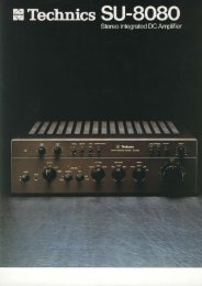
<strong>With</strong> <strong>this</strong> <strong>amplifier</strong>, <strong>you</strong> <strong>can</strong> <strong>obtain</strong> <strong>the</strong> <strong>best</strong> of<br />
both worlds. Technics' "New Class A" amolifier<br />
circuit combines class A output with stable load<br />
condition on all stages. Also, <strong>the</strong> undistorted<br />
sound quality of class A and <strong>the</strong> efficient, highoutput<br />
power of class B are available within a<br />
single <strong>amplifier</strong>. You don't have to trade<br />
efficiency and price for sound quality, or<br />
switching distortion for high output.<br />
The SU-V6's facts and figures support <strong>the</strong>se<br />
claims: 70 watts per channel, both channels<br />
driven into B ohms, trom 20 Hzto2O kHz with no<br />
more than O.OO7% total harmonic distortion.<br />
The most important fact, though, is that <strong>this</strong><br />
Class B amplilier output<br />
wavefom and distortion<br />
wavefom (at 20 kHz)<br />
New class A <strong>amplifier</strong> outpul<br />
wavefom and distortion<br />
wavefom (at 20 kHz)<br />
integrated amplif ier's f aithf ully reproduced<br />
sound exhibits <strong>the</strong> effortless smoothness of true<br />
class A amplification. And yet all <strong>this</strong> is available<br />
at a fraction of a conventional class A amolifier's<br />
cost.<br />
New Glass A and Straight DC<br />
Provide Both Quality and Quantity<br />
Quality of reproduced sound and quantity of<br />
output power are <strong>the</strong> two general aims we were<br />
striving to develop in <strong>the</strong> advanced circuitry<br />
incorporated in <strong>the</strong> SU-V6.<br />
To test <strong>the</strong> success of our circuit designs,<br />
we have employed a new method of analysis<br />
called 3DA (first used in <strong>the</strong> development of<br />
<strong>the</strong> SU-8099 integrated amp), which stands for<br />
"3-Dimensional Analysis." <strong>With</strong> <strong>the</strong> aid of a<br />
computer, <strong>this</strong> system enables us to test<br />
performance at 4,000 points and express <strong>the</strong><br />
results in 3-dimensional graphic form. From our<br />
extensive research using 3DA, we have found<br />
that performance requirements within <strong>the</strong> audio<br />
spectrum are <strong>best</strong> satisfied by building <strong>amplifier</strong>s<br />
that exhibit good performance characteristics<br />
Output Transistor Current Waveform<br />
from 0 Hz (DC) at <strong>the</strong> bottom of <strong>the</strong> frequency<br />
range, all <strong>the</strong> way up to nearly 100 kHz in <strong>the</strong><br />
ultra-high range (it's undesirable to go much<br />
higher than <strong>this</strong> point, given currently available<br />
circuit components).<br />
To achieve oerformance within <strong>the</strong>se<br />
considerations, we have used a number of<br />
advanced circuit configurations, <strong>the</strong> two most<br />
important of which are "New Class A" and<br />
"Straight DC."<br />
New Class A with Synchro Bias for<br />
Better High Frequency Response<br />
Transistor switching is a major cause of highfrequency<br />
distortion in class B and class AB<br />
<strong>amplifier</strong> designs. ln class B designs, two outpul<br />
transistors are used for each channel. The<br />
"upper" transistor handles <strong>the</strong> positive half of<br />
<strong>the</strong> waveform and <strong>the</strong> "lower" transistor handles<br />
<strong>the</strong> negative half. But problems occur when <strong>the</strong><br />
signal crosses <strong>the</strong> zero point; one transistor turns<br />
off and <strong>the</strong> o<strong>the</strong>r turns on. During <strong>this</strong> crossover,<br />
"switching distortion" is generated. This takes<br />
<strong>the</strong> form of brief pulses with very sharp peaks,<br />
which produce high-order harmonic distortion.<br />
NFB (negative feedback) does not cope with<br />
switching distortion effectively, despite its<br />
usefulness in combating ordinary forms of<br />
distortion. This switching distortion <strong>can</strong> also<br />
result in intermodulation distortion which<br />
muddies reproduced sound to a greater degree
than might be expected from a simple examination<br />
of an oscilloscope trace. In class A, <strong>the</strong> same<br />
transistor handles <strong>the</strong> entire waveform, but a<br />
large idling current is required to operate <strong>the</strong><br />
transistor even when <strong>the</strong>re is no audio input<br />
signal. Although <strong>this</strong> prevents any form of<br />
switching distortion, it also results in very low<br />
efficiency. Large heat sinks must be provided to<br />
dissipate <strong>the</strong> substantial amount of excess heat<br />
that is created. Price is correspondingly high.<br />
In our New Class A circuihy, <strong>the</strong> output transistor<br />
bias current is synchronized with <strong>the</strong> positive and<br />
negative swings of <strong>the</strong>.input signal so that <strong>the</strong><br />
output transistors are always in an active state.<br />
<strong>With</strong> <strong>this</strong> remarkable circuitry, switching<br />
distortion is eliminated since <strong>the</strong> transistors are<br />
never allowed to switch off. Because of <strong>this</strong><br />
synchronized operation, we call <strong>this</strong> "synchro<br />
bias." Besides preventing switching distortion in<br />
<strong>the</strong> output waveform, it also presents linear load<br />
conditions to <strong>the</strong> voltage amplification stage.<br />
Predriver load fluctuation is also minimized.<br />
The result is <strong>the</strong> virtual elimination of "crossover<br />
distortion."<br />
"Straight DC" Configuration for<br />
Direct Coupling Between DC Power<br />
Amp Section and High Level Input<br />
Signals<br />
The SU-V6's design takes full advantage of <strong>the</strong><br />
excellent low-range f requency response, phaselinearity,<br />
and low distortion inherent in our<br />
refined DC pourer amp design. By increasing <strong>the</strong><br />
gain of <strong>the</strong> power amp section, we have made it<br />
possible to directly couple high level inputs, such<br />
as tuner, tape, and AUX sources, to <strong>the</strong> power<br />
amp input. The resulting improvement in low<br />
range fidelity is a good example of what <strong>can</strong> be<br />
achieved with an innovative, yet uncomplicated,<br />
approach to integrated amp design. In fact, <strong>you</strong><br />
could view <strong>this</strong> configuration as simply a phono<br />
equalizer and a DC power amp.<br />
While <strong>this</strong> characterizes <strong>the</strong> "simple is <strong>best</strong>"<br />
philosophy, some additional innovations were<br />
necessary to <strong>obtain</strong> <strong>the</strong> desired performance<br />
goals. First of all, a high-gain amp is required to<br />
raise typical "high level" inputs of 150 mV-<br />
200 mV to output levels of 70 W-100 W.<br />
Fur<strong>the</strong>rmore, any tendency toward temperature<br />
deoendent DC drift must be avoided since <strong>the</strong><br />
amp's gain extends all <strong>the</strong> way down to DC in <strong>the</strong><br />
low range.<br />
To <strong>obtain</strong> high gain, Technics'SU-V6 amp<br />
employs a linear cascode, 3-stage Darlington<br />
configuration which provides excellent openloop<br />
performance. As a result, only 45 dB NFB is<br />
required to achieve <strong>the</strong> 0.007%fHD rating at<br />
70 Woutput.<br />
To combat DC drift, 1-chip dual FET's are used<br />
for <strong>the</strong> first stage differential <strong>amplifier</strong>. Since <strong>this</strong><br />
prevents mutual temperature differences, DC<br />
drift is reduced to a mere + 10 mV from - 10'C to<br />
+50'c.<br />
Concentrated Power Block (CPB)<br />
Prevents Distortion from<br />
Electromagnetic Induction<br />
<strong>With</strong> <strong>the</strong> strikingly clean high range response<br />
<strong>obtain</strong>ed from our New Class A synchro bias<br />
circuitry, we made sure that nothing would<br />
interfere with proper performance under<br />
practical signal handling conditions.<br />
Our concentrated power block was developed to<br />
prevent electromagnetic induction between<br />
those portions of <strong>the</strong> circuitry which handle large<br />
amounts of current and those which handle<br />
smaller signals. The power supply and output<br />
stage were concentrated in one integrated unit to<br />
create <strong>the</strong> shortest possible connections.<br />
<strong>With</strong> <strong>the</strong> addition of low impedance laminated<br />
bus lines, <strong>the</strong> power supply loop was minimized.<br />
Ano<strong>the</strong>r advantage of CPB is that it virtually<br />
eliminates signifi<strong>can</strong>t dif ferences in performance<br />
between individual units. Consequently, <strong>you</strong> <strong>can</strong><br />
expect a maximumO.OOTo/o THD for anv<br />
individual SU-V6 amp.<br />
ICL Phono EQ Circuit Emplovinq<br />
Ultra-Low Noise FETs Pei'miis '<br />
Direct MC Cartridge Connection<br />
The first stage of <strong>the</strong> phono equalizer is a<br />
differential <strong>amplifier</strong> with ultra-low noise dual<br />
FETs. As a result, no input capacitors are<br />
necessary. A mere increase in equalizer gain,<br />
ra<strong>the</strong>r than an additional pre-preamp or step-up<br />
transformer, is all that is needed for MC cartridge<br />
compatibility. When <strong>the</strong> amp is in <strong>the</strong> straight D-C<br />
mode, <strong>the</strong> only capacitor in <strong>the</strong> entire amp circuit,<br />
whe<strong>the</strong>r <strong>the</strong> input is MC or MM, is <strong>the</strong> EQ output<br />
capacitor.<br />
Heavy Duty Power Supplies<br />
In an audio <strong>amplifier</strong>, <strong>the</strong> power supply must be<br />
able to meet <strong>the</strong> changes in impedance<br />
presented by <strong>the</strong> speaker systems. Depending<br />
on <strong>the</strong> frequency, <strong>this</strong> figure <strong>can</strong> range from<br />
below 4 ohms up to as high as 30 ohms for a<br />
speaker system rated at 8 ohms.<br />
In <strong>the</strong> SU-V6, independent rectifier and ripple<br />
filter circuits are provided for <strong>the</strong> left and right<br />
channels to assure truly stable DC power.<br />
Fur<strong>the</strong>rmore, <strong>the</strong> power transformer coils float in<br />
a special resin within shielded cases to prevent<br />
power supply hum.<br />
Independent Recording Selector<br />
with 2-Way Dubbing<br />
<strong>With</strong> <strong>this</strong> versatile arrangement <strong>you</strong> <strong>can</strong> record<br />
from one source while listening to ano<strong>the</strong>r since<br />
<strong>the</strong> input and recording selectors are separate.<br />
Tape inputs are positioned on both <strong>the</strong> input<br />
selector and <strong>the</strong> recording selector so that <strong>you</strong><br />
<strong>can</strong> record while listening to ano<strong>the</strong>r source<br />
(such as a disc), if <strong>you</strong> wish.<br />
Remote Action Switches Eliminate<br />
Excess Wiring<br />
Remote action switches are employed on <strong>the</strong><br />
input selector, recording selector, and phono<br />
selector. Therefore, switching takes place at <strong>the</strong><br />
ideal location within <strong>the</strong> circuitry.<br />
This contributes to sound quality by minimizing<br />
<strong>the</strong> chances of signal degradation due to<br />
extensive wiring.<br />
O<strong>the</strong>r Features<br />
oHigh filter to cut out high frequency noise such<br />
as record scratches and tape hiss.<br />
oFront-panel speaker selector lets <strong>you</strong> select<br />
ei<strong>the</strong>r of two pairs of speaker systems (A or B)<br />
or both at once (A+B).<br />
aTone controls defeated at center oosition<br />
setting.
Rear Panel Facilities<br />
89<br />
10<br />
11<br />
ffi (p'(p (b<br />
::<br />
,:Y 17<br />
a .,r) $ xww<br />
n wq<br />
1. PHONO inputs<br />
2. TUNER inputs<br />
AUX inputs<br />
A<br />
TAPE DECK I Recording outputs<br />
5. TAPE DECK 1 Playback inputs<br />
6. TAPE DECK 2 Recording outputs<br />
7. TAPE DECK 2 Playback inPuts<br />
8. Ground terminal<br />
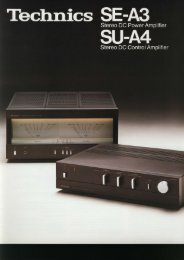
ST-S7 and SU-V6<br />
9. Speaker terminals (main)<br />
10. Speaker terminals (remote)<br />
'1 '1 . Voltage adjuster The ST-S7 Quartz Syn<strong>the</strong>sizer FM/AM Stereo Tuner is iust <strong>the</strong> right<br />
companion for <strong>you</strong>r SU-V6. <strong>With</strong> <strong>the</strong> same clean, attractive styling and<br />
outstanding performance standards, it perfectly complements <strong>the</strong> SU-V6<br />
Integrated DC Amplifier.<br />
20 Hz-20 kHz continuous power output<br />
both channels driven 80Wx2 (4())<br />
70Wx2 (8cl)<br />
40 Hz-1 6 kHz continuous power output<br />
both channels driven<br />
1 kHz continuous power output<br />
both channels driven<br />
Total harmonic distortion<br />
rated oower<br />
at20 Hz-2O kHz<br />
B0Wx2 (4O)<br />
70Wx2 (80)<br />
90Wx2 (4O)<br />
74Wx2 (8O)<br />
o.o2% ga)<br />
0.007% (8o)<br />
al 40 Hz-16 kqz<br />
0.o2% ga)<br />
0.007% (8o)<br />
at 1 kHz<br />
0.01% (4o)<br />
0.007% (8o)<br />
half power<br />
at 20 Hz-2O kHz<br />
0.007% (8o)<br />
at 1 kHz<br />
0.003% (8o)<br />
-26 dB power at 1 kHz 0.05% (4())<br />
50mWpoweratl kHz 0.08% (4o)<br />
Intermodulation distortion<br />
rated power<br />
at 250 Hz:8 k{z=4:1 ,4Q O.O2%<br />
at60Hz:7 kHz:4:1, SMPTE, 8A 0.0O7%<br />
Power bandwidth both channels driven, -3 dB<br />
THD. 0.03%,5 Hz-60 kHz (4o)<br />
THD. O.O2%, 5 Hz-60 kHz (8O)<br />
Residual hum & noise (Straight DC) 0.3 mV<br />
Damping factor<br />
30 (4O), 60 (8O)<br />
Headphones output level * ,tP"H3?,Uraaon<br />
Load imoedance<br />
MAIN or REMOTE<br />
MAIN and REMOTE<br />
Input sensitivity & impedance<br />
PHONO MM<br />
MC<br />
TUNER, AUX<br />
TAPE 1, REC/PLAY<br />
TAPE2<br />
Phono maximum input voltage<br />
at 1 kHz. RMS. THD 0.01 %<br />
MM<br />
MC<br />
s/N<br />
rated power4()<br />
PHONO MM<br />
MC<br />
TUNER, AUX<br />
-26 dB power 4ft<br />
PHONO MM<br />
MC<br />
TUNER, AUX<br />
50 mW power4O<br />
PHONO MM<br />
MC<br />
TUNER, AUX<br />
4()-16()<br />
8f)-16()<br />
2.5mV/47 kQ<br />
170 p.V/474<br />
150 mV/36 ko<br />
170 mV/39 kO<br />
'150 mV/36 ko<br />
150 mV<br />
10 mV<br />
78 dB (86 dB, rHF A)<br />
68 dB (68 dB, rHF A,<br />
250 pV input)<br />
92 dB (106 dB, IHF A)<br />
67 dB<br />
65 dB<br />
68 dB<br />
64 dB<br />
62 dB<br />
65 dB<br />
Frequency response<br />
PHONO RIAA standard curve +0.5 dB<br />
(30 Hz-l5 kHz)<br />
TUNER. AUX. TAPE<br />
(Straight DC) DC-150 kHz (-3 dB)<br />
+0, -0.3 dB (2O Hz-2O kHz)<br />
Tone controls<br />
BASS<br />
50 Hz, +10 dB--10 dB<br />
TREBLE 20kHz, +10 d8--10 d8<br />
High-cut filter<br />
7 kHz, -6 dBloct<br />
Subsonic filter<br />
20 Hz, -12 dB/oct<br />
Loudness control<br />
(volume at -30 dB)<br />
50 Hz, +9 dB<br />
Output voltage & impedance<br />
REC OUT<br />
150 mV<br />
REC/PLAY<br />
30 mV/82 kO<br />
Channel balance<br />
AUX, 250 Hz-6300 Hz<br />
+1.0 dB<br />
Channel separation<br />
AUX,1 kHz<br />
55 dB<br />
GENERAL<br />
Power consumption<br />
760 W<br />
Power supply AC 110/120/220/240V,<br />
50/60 Hz<br />
Dimensions (WxHxD) 430x153x351 mm<br />
(16-15/16" x 6-1 /32" x 13-13/ 16")<br />
Weight<br />
12.5 kg (27.6lb)<br />
Note: Total harmonic distortion is measured by<br />
<strong>the</strong> digital spectrum analyzel<br />
(HP 3045 system).<br />
SD8OFOl OE2<br />
Technics<br />
Matsushita Electric<br />
Specifications subject to change without notice. Printed in Japan.