instructions - Firestone Industrial Products
instructions - Firestone Industrial Products
instructions - Firestone Industrial Products

You also want an ePaper? Increase the reach of your titles
YUMPU automatically turns print PDFs into web optimized ePapers that Google loves.
2101<br />
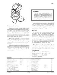
WARNING:<br />
Do not inflate this assembly when it is unrestricted.<br />
The assembly must be restricted by the suspension<br />
or other adequate structure. Do not inflate beyond<br />
100 P.S.I. Improper use or over inflation may cause<br />
property damage or severe personal injury.<br />
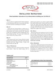
INSTALLATION INSTRUCTIONS<br />
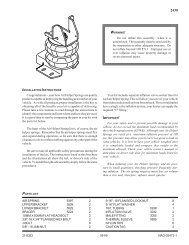
Congratulations - your new Air Helper Springs are quality<br />
products capable of improving the handling and comfort of your<br />
vehicle. As with all products, proper installation is the key to<br />
obtaining all of the benefits your kit is capable of delivering.<br />
Please take a few minutes to read through the <strong>instructions</strong> to<br />
identify the components and learn where and how they are used.<br />
It is a good idea to start by comparing the parts in your kit with<br />
the parts list below.<br />
The heart of the air helper spring kit is, of course, the air<br />
helper springs. Remember that the air helper springs must flex<br />
and expand during operation, so be sure that there is enough<br />
clearance to do so without rubbing against any other part of the<br />
vehicle.<br />
Be sure to take all applicable safety precautions during the<br />
installation of the kit. The <strong>instructions</strong> listed in this brochure<br />
and the illustrations all show the left, or driver’s side of the<br />
vehicle. To install the right side assembly simply follow the same<br />
procedures.<br />
Your kit includes separate inflation valves and air lines for<br />
each air helper spring. This will allow you to level your vehicle<br />
from side to side as well as from front to back. If you would rather<br />
have a single valve inflation system, your dealer can supply the<br />
required "T" fitting.<br />
IMPORTANT!<br />
For your safety and to prevent possible damage to your<br />
vehicle, do not exceed the maximum load recommended by the<br />
vehicle manufacturer (GVWR). Although your Air Helper<br />
Springs are rated at a maximum inflation pressure of 100 P.S.I.,<br />
this pressure may allow you to carry too great a load on some<br />
vehicles. Check your vehicle owner’s manual for maximum<br />
loads listed for your vehicle.<br />
When inflating your Air Helper Springs, add air pressure<br />
in small quantities, checking pressure frequently during<br />
inflation. The air spring requires much less air volume than<br />
a tire and, therefore, inflates much quicker.<br />
PARTS LIST<br />
267C AIR SPRING 6781 2<br />
UPPER BRACKET (RIGHT) 5157 1<br />
UPPER BRACKET (LEFT) 5158 1<br />
LOWER BRACKET 5159 2<br />
AXLE STRAP 1163 2<br />
HEAT SHIELD 1004 1<br />
3/8" -16 x 1" HEX BOLT 4<br />
3/8" -16" x 3" CARRIAGE BOLT 4<br />
3/8" -16 FLANGED LOCK NUT 12<br />
3/8" -16 x 3/4" HEX BOLT 2<br />
1/4" -20 x 1" HEX BOLT 2<br />
1/4" FLAT WASHER 4<br />
3/8" LARGE FLAT WASHER 4<br />
1/4" LOCK WASHER 2<br />
1/4" HEX NUT 2<br />
PUSH-TO-CONNECT<br />
MALE AIR FITTING 3046 2<br />
PUSH-TO-CONNECT<br />
INFLATION VALVE 3032 2<br />
5/16" FLAT WASHER 4<br />
AIR LINE TUBING 1<br />
NYLON TIE 6<br />
THERMAL SLEEVE 2<br />
21-8156 12-03 NCD-5988-2
2101<br />
FIGURE "A"<br />
NOTE: Both illustrations are of the left, or drivers<br />
side, of the vehicle. Reverse any orientations when<br />
assembling and installing the right, or passenger, side<br />
of the vehicle.<br />
UPPER BRACKET<br />
KIT ASSEMBLY<br />
3/8” -16<br />
FLANGED<br />
HEX NUT<br />
1/4” -20 x 1”<br />
HEX BOLT<br />
KIT TO FRAME ASSEMBLY<br />
1/4” FLAT<br />
WASHER<br />
1/4” FLAT<br />
WASHER<br />
3/8” -16<br />
FLANGED<br />
FRAME<br />
1/4” LOCK<br />
WASHER<br />
1/4” -20<br />
HEX NUT<br />
HEX NUT 3/8” -16”<br />
FLANGED<br />
HEX NUT<br />
3/8” LARGE<br />
WASHER<br />
(SEE NOTE 1)<br />
AIR SPRING<br />
3/8” LARGE<br />
WASHER<br />
(SEE NOTE 1)<br />
AIR LINE<br />
AIR<br />
FITTING<br />
USE THIS HOLE<br />
FOR 2WD<br />
VEHICLES<br />
USE THIS<br />
HOLE FOR<br />
4WD VEHICLES<br />
3/8” -16 x 3”<br />
CARRIAGE<br />
BOLT<br />
3/8” -16 x 1”<br />
HEX BOLT<br />
LOWER<br />
BRACKET<br />
3/8” -16 x 3/4”<br />
HEX BOLT<br />
3/8” -16 x 1”<br />
HEX BOLT<br />
3/8” -16 x 3”<br />
CARRIAGE BOLT<br />
LEAF STACK<br />
AXLE<br />
WHEEL<br />
AXLE STRAP<br />
FRONT<br />
NOTE 1:<br />
Use 3/8” large flat washer<br />
between upper bracket and<br />
frame rail only if rivet head is<br />
present on bottom of frame.<br />
Rivet head will prevent flush<br />
mounting of the upper bracket<br />
to the frame rail.<br />
3/8” -16<br />
FLANGED LOCK NUT
TWO-WHEEL<br />
DRIVE VEHICLES<br />
SOME FOUR-WHEEL<br />
DRIVE VEHICLES MAY<br />
HAVE BOLTS, OTHERS<br />
WILL HAVE RIVETS<br />
FRONT<br />
FIGURE "B"<br />
FIGURE "C"<br />
FIGURE "D"<br />
OVER-BENT<br />
TAB<br />
VIEW OF DRIVER’S SIDE ASSEMBLY<br />
FROM INSIDE OF VEHICLE<br />
UPPER BRACKET<br />
LEAF<br />
STACK<br />
DRIVER'S SIDE<br />
FRONT<br />
FRAME RAIL<br />
SHOCK<br />
BRACKET<br />
BRACKET STRAP<br />
FIGURE "E"<br />
AIR SPRING<br />
LOWER BRACKET<br />
AXLE<br />
BRAKE LINE<br />
STEP 1 - PREPARE THE VEHICLE<br />
Remove the positive battery cable. With the vehicle on a solid, level surface<br />
chock the front wheels. Raise the vehicle by the axle and remove the rear wheels.<br />
After the removal of the wheels lower the vehicle so the axle rests on jack stands<br />
rated for your vehicles weight.<br />
This installation assumes that there is no load in the truck.<br />
NOTE:<br />
This kit is designed to fit both two-wheel and four-wheel drive vehicles. The<br />
jounce bumper and brackets must be removed for installation of this kit. The<br />
jounce bumper and bracket on the two-wheel drive can be unbolted and removed<br />
see Figure "B". The jounce bumper and bracket on the four-wheel drive may be<br />
bolted or riveted in place, depending on model year. Simply unbolt the jounce<br />
bumper bracket and remove from the frame see Figure "C". On older models,<br />
remove the jounce bumper by drilling out two rivets that fasten the bracket to the<br />
frame. Complete the removal by cutting off the heads with a cold chisel. The<br />
completion of the kit installation is the same for the two-wheel and four-wheel<br />
drive.<br />
STEP 2 - PRE-ASSEMBLE THE KIT<br />
This kit is supplied with a right and left upper bracket. Begin by installing the<br />
left (driver's side) upper bracket. This bracket will have the "over-bent tab" see<br />
Figure "D". The lower bracket is the same for both sides. Align the studs on the<br />
top of one of the air springs with the mounting holes in the upper bracket while<br />
ensuring that the air hole is visible through the slot in the upper bracket. Insert<br />
the studs into the holes and secure the air spring to the upper bracket with 3/8"<br />
-16 flanged lock nuts see Figure "A". Next, install the male push-to-connect air<br />
fitting in the air inflation hole. Tighten the air fitting securely to engage the orange<br />
thread sealant.<br />
To attach the lower bracket to the air spring, first position the bracket on the<br />
axle housing over the jounce pad see Figures "A" & "E". Position the bracket so<br />
that the narrow end is toward the center of the vehicle. The air spring must be<br />
secured to the lower bracket through the forward hole. Once the correct mounting<br />
hole for the lower bracket has been identified, remove the bracket from the axle and<br />
fasten to the air spring using a 3/8" -16 x 3/4" hex bolt (finger tight). Note that<br />
this bolt will be tightened in Step 3.<br />
STEP 3 - INSTALL THE ASSEMBLY TO THE VEHICLE<br />
Set the assembly in place on the axle housing over the jounce pad. The lower<br />
bracket should butt against the U-bolts on the leaf spring see Figure "E". Position<br />
the assembly so that the upper bracket is aligned vertically against the outside<br />
surface of the frame rail.<br />
On some vehicles there may be a rivet head on the bottom of the bottom surface<br />
of the frame rail that will prevent the upper bracket from being mounted flush<br />
against the frame. To assure that the upper bracket clears the rivet head, install<br />
four large flat washers between the upper bracket and the bottom surface of the<br />
frame rail see Figure "A". Installation of the flat washers is only necessary if your<br />
vehicle has a rivet head on the bottom of the frame rail. Insert a 1/4" -20 x 1" bolt<br />
through the vertical tab of the upper bracket and an existing hole in the frame rail.<br />
Secure with washers and a nut see Figure "A". On some models, a hole must be<br />
drilled in the frame rail for the bolt to pass through. Using the upper bracket as<br />
a template, drill a 5/16" hole though the frame rail. Make sure that all electrical,<br />
brake, and fuel lines are cleared from the path of the drill.<br />
The tabs on the bracket will be secured to the lower frame flange using 3/8"<br />
flanged lock nuts and 3/8"-16 x 1" hex bolts see Figure "A". Note: on the driver's<br />
side of the vehicle the 1/4" bolt will also hold a clip (on some models) used to<br />
hold brake and fuel lines. Secure the clip to the 1/4" bolt to secure the lines.<br />
Align the lower bracket against the U-bolts over the leaf spring stack see<br />
Figure "E". After the bracket has been squared with the U-bolts, tighten the<br />
3/8" hex bolt to secure the lower bracket to the air spring. Next, insert two<br />
3/8" -16 x 3" carriage bolts into the square holes on the lower bracket. Install one<br />
axle strap on the bottom of the axle housing see Figure "A". Slide the axle strap
HEAT SHIELD<br />
AIR<br />
SPRINGS<br />
AIR LINE<br />
PUSH-TO-CONNECT<br />
INFLATION VALVE<br />
BODY OF<br />
VEHICLE<br />
FIGURE "F"<br />
BUMPER<br />
FIGURE "G"<br />
FIGURE "H"<br />
AIR HOSE<br />
FLAT WASHER<br />
HEX NUT<br />
VALVE CAP<br />
INFLATION<br />
VALVES<br />
on to the carriage bolts and secure with 3/8" -16 flanged lock nuts. This installation<br />
will hold the lower bracket in place. Note: When installing the left-side assembly,<br />
it will be necessary to tie the parking brake line to the sway bar to prevent it from<br />
contacting the air spring in normal operation. There must be at leat 1/2" of<br />
clearance between the inflated air spring and any other part of the vehicle.<br />
STEP 4 - INSTALL THE PASSENGER'S SIDE ASSEMBLY<br />
Follow steps 1 - 4 for assembly and installation of the passenger's side<br />
assembly. On the passenger's side it will be necessary to install a heat shield<br />
between the upper bracket and the air spring to protect the air spring from the<br />
exhaust pipe heat see Figure "F". Position the heat shield so that it will reflect<br />
radiant heat from the point on the exhaust pipe closest to the air spring. The heat<br />
shield should be positioned so that it does not contact the axle housing as the<br />
suspension compresses.<br />
STEP 5 - INSTALL THE AIR LINE AND THE INFLATION VALVE<br />
Uncoil the air line tubing and cut it into two equal lengths. DO NOT FOLD<br />
OR KINK THE TUBING. Try to make the cut as square as possible. Insert one<br />
end of the tubing into the air fitting installed in the top of the air helper spring. Push<br />
the tubing into the fitting as far as possible.<br />
Select a location on the vehicle for the air inflation valves. The location can<br />
be on the bumper or the body of the vehicle, as long as it is in a protected location<br />
so the valve will not be damaged, but maintain accessibility for the air chuck see<br />
Figure "G". Drill a 5/16" hole and install the air inflation valve using two 5/16"<br />
flat washers per valve as supports see Figure "H". Run the tubing from the air<br />
helper spring to the inflation valve, routing it to avoid direct heat from the exhaust<br />
pipe and away from sharp edges. Thermal sleeves have been provided for these<br />
conditions. If a thermal sleeve is required simply slide the sleeve over the air line<br />
tubing to the location requiring protection. The air line tubing should not be bent<br />
or curved sharply as it may buckle. Secure the tubing in place with the nylon ties<br />
provided. Push the end of the air line tubing into the inflation valve as illustrated<br />
see Figure "H".<br />
STEP 6 - CHECK THE AIR SYSTEM<br />
Once the inflation valves are installed inflate the air helper springs to 70 P.S.I.<br />
and check the fittings for air leaks with an applied solution of soap and water. If<br />
a leak is detected at a tubing connection, check to make sure that the tube is cut<br />
as square as possible and that it is pushed completely into the fitting. The tubing<br />
can easily be removed from the fitting by first releasing the pressure from the air<br />
spring, then by pushing the collar towards the body of the fitting and then pulling<br />
out the tube. If a leak is detected where the air fitting screws into the spring, release<br />
the air pressure, then remove the tubing as described above, then screw the brass<br />
fitting into the air spring one additional turn or until the leak stops. Reinstall the<br />
tubing and reinflate the air springs and check for leaks as noted above.<br />
This now completes the installation. Install the wheels and torque the lug nuts to the manufactures specifications. Raise the<br />
vehicle by the rear axle and remove the jack stands and lower the vehicle back onto the ground. Re-attach the positive battery<br />
cable and remove the wheel chocks from the wheels. Before proceeding, check once again to be sure you have proper clearance<br />
around the air springs. With a load on your vehicle and the air helper springs inflated, you must have at least 1/2" clearance around<br />
the air springs. As a general rule, the air helper springs will support approximately 50 lbs. of load for each P.S.I. of inflation pressure<br />
(per pair). For example, 50 P.S.I. of inflation pressure will support a load of 2500 lbs. per pair of air helper springs. FOR BEST RIDE<br />
use only enough air pressure in the air helper springs to level the vehicle when viewed from the side (front to rear). This amount<br />
will vary depending on the load, location of load, condition of existing suspension and personal preference.<br />
NOTE:<br />
Too much air pressure in the air helper springs will result in a firmer ride, while too little air pressure will allow the air helper<br />
spring to bottom out over rough conditions. Too little air pressure will also not provide the possible improvement in handling.<br />
TO PREVENT POSSIBLE DAMAGE MAINTAIN A MINIMUM OF 5 P.S.I. IN THE AIR HELPER SPRINGS AT ALL TIMES.<br />
NOTE:<br />
Once the air helper springs are installed, it is recommended that the vehicle not be lifted by the frame, as over-extension may<br />
occur, resulting in damage to the air helper springs. However, should it become necessary to raise the vehicle by the frame, deflate<br />
both air helper springs completely.